Evaluating the Effect of Wheel Polygons on Dynamic Track Performance in High-Speed Railway Systems Using Co-Simulation Analysis


1
Provincial Key Lab of Traffic Safety and Control, School of Traffic and Transportation, Shijiazhuang Tiedao University, Shijiazhuang 050043, China
2
School of Civil Engineering, Southwest Jiaotong University, Chengdu 610031, China
3
Beijing MTR Corporation Limited, Beijing 100068, China
4
Structure Health Monitoring and Control Institute, Shijiazhuang Tiedao University, Shijiazhuang 050043, China
*
Author to whom correspondence should be addressed.
Appl. Sci. 2019, 9(19), 4165; https://doi.org/10.3390/app9194165
Submission received: 28 July 2019
/
Revised: 26 September 2019
/
Accepted: 30 September 2019
/
Published: 4 October 2019
Abstract
:With increases in train speed and traffic density, problems due to wheel polygons and those caused by wheel–rail impacts will increase accordingly, which will affect train operational safety and passenger ride comfort. This paper investigates the effects of polygonal wheels on the dynamic performance of the track in a high-speed railway system. The wheel–rail interaction forces caused by wheel polygons are determined using a dynamic vehicle–track model, and the results are entered into a slab track finite element model. The influence of the harmonic order and out-of-roundness (OOR) amplitude of wheel polygons on the transient dynamic characteristics of the track(von Mises equivalent stress, displacement, and acceleration) is examined under high-speed conditions. The results indicate that the vibration acceleration and von Mises equivalent stress of the rail increase in proportion to the harmonic order and the OOR amplitude and velocity of a polygonized wheel. The vibration displacement of the rail first increases and then decreases with a change in the harmonic order, and reaches a maximum at the ninth order. The dynamic responses of the concrete slab layer, cement-asphalt layer, and support layer increase linearly with the harmonic order and amplitude of wheel polygons and decrease from top to bottom. Through a combination of numerical simulations and real-time monitoring of rail vibrations, this study provides guidance on potential sensor locations to identify polygonized wheels before they fail.

1. Introduction
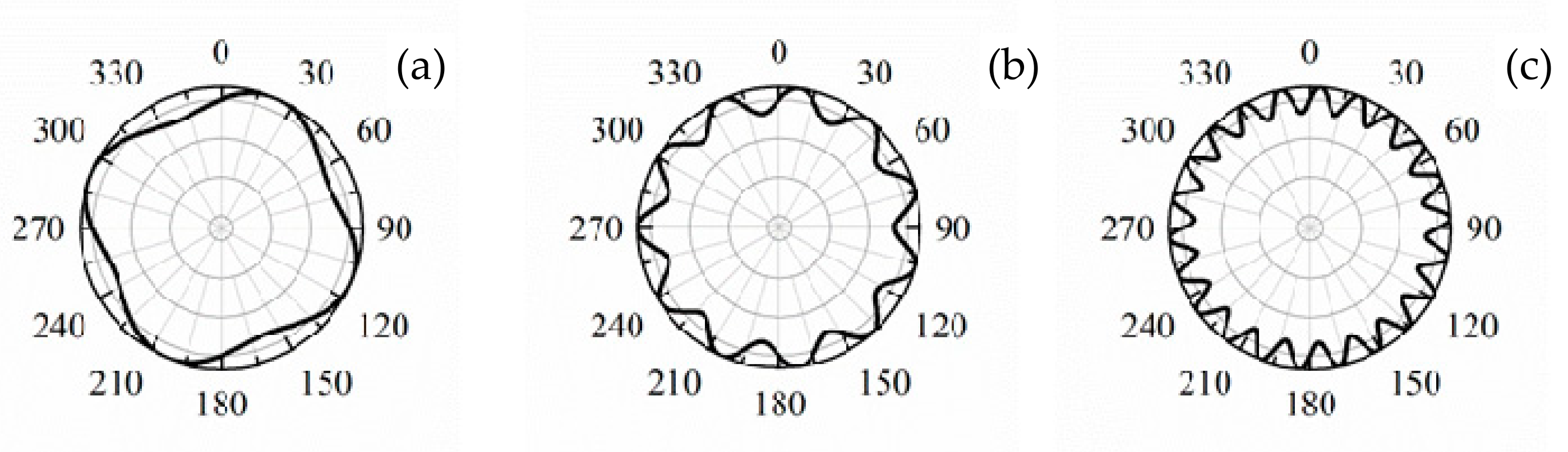
The phenomenon of train wheel polygons—that is, wheels with a certain degree of out-of-roundness (OOR)—is a well-known problem for high-speed railways [1].The term “wheel polygon” refers to periodic radial deviations from the ideal round shape of the circumference of the wheel. Figure 1 shows the shapes of typical polygonal wheels with different harmonic OOR orders. The technical term “harmonic order” refers to a sinusoidal radial deformation of the circumference with a specific period. The “OOR amplitude” is defined as the deviation of the radius from the nominal constant value. At present, there is no explicit conclusion regarding the mechanism whereby wheel polygons are generated. However, polygonal wheels produce a number of problems. For example, at speeds above 200km/h, this phenomenon will cause considerable vibrations, which are transmitted to the train compartments via the wheels and from the rails to the track components, resulting in the deterioration of infrastructure, noise disturbance, and an increase in maintenance costs [2].
There has been considerable research on the wear characteristics caused by this phenomenon and the dynamic responses. Early studies of wheel OOR were carried out in Germany, Sweden, Australia, and other developed regions using experimental studies and numerical simulations to analyze the mechanism of their occurrence and development [3,4,5].Most reported causes of the formation of wheel polygons involve the inhomogeneity of tread material, braking characteristics, wheel–rail rolling contact, axle bending modes, manufacturing errors, and misalignment during profiling [6,7,8]. Criteria for determining whether OOR wheels should be removed have been proposed in the United States, United Kingdom, and other countries in an attempt to reduce infrastructure maintenance costs and comply with noise legislation [9,10].With the rapid development of high-speed railways in China, extensive field data show that polygonized wheels are very common in high-speed trains. This phenomenon has attracted the attention of researchers, and there is an economic incentive to detect and replace OOR wheels in good time. The causes and enlargement of wheel polygons [11,12] and the effects of polygonal wheels on vehicle stability and train operational safety [13,14,15] have been discussed by researchers at various universities in China. In addition, a few studies [16,17] focused on simulating the dynamics of high-speed railway vehicles on flexible tracks.
Previous studies provide an initial insight into the origin of wheel polygons and their influence on vehicle dynamics. However, to the best of the authors’ knowledge, little attention has been paid to the track dynamics resulting from wheel polygons in high-speed operations. The goal of this paper is to study the influence of the wheel polygon order, OOR amplitude, and train speed on the dynamic performance of a slab track. Our analysis is based on a co-simulation method using multi-body dynamics simulation software Universal Mechanism (V8.3, Laboratory of Computational Mechanics, Bryansk State Technical University, Bryansk, Russia) and finite element software ANSYS (R18.0, ANSYS Inc., Canonsburg, PA, USA). Our research results provide guidance on potential sensor locations for identifying polygonized wheels in-service before they fail through the application of a rail vibration monitoring system.
2. Establishment of Numerical Simulation Model
2.1. Model of Vehicle–Track Coupled Dynamics
In order to simulate the dynamics of railway vehicles on flexible tracks and keep track of the inherent wheel–rail interaction, we simulate each of the two subsystems—vehicle and rail—with appropriate software concurrently and exchange the interfacing data at discrete communication points. The track model has been implemented in ANSYS, allowing a sufficiently accurate approximation of its flexibility, while the vehicle’s motion, including its complex wheel–rail interaction, is reproduced in the Universal Mechanism (UM) software [18,19].Using this co-simulation method, the wheel–rail interaction forces resulting from wheel polygons are determined by UM software. These forces are then entered into a slab track finite element model. A diagram of the analytic workflow is shown in Figure 2.
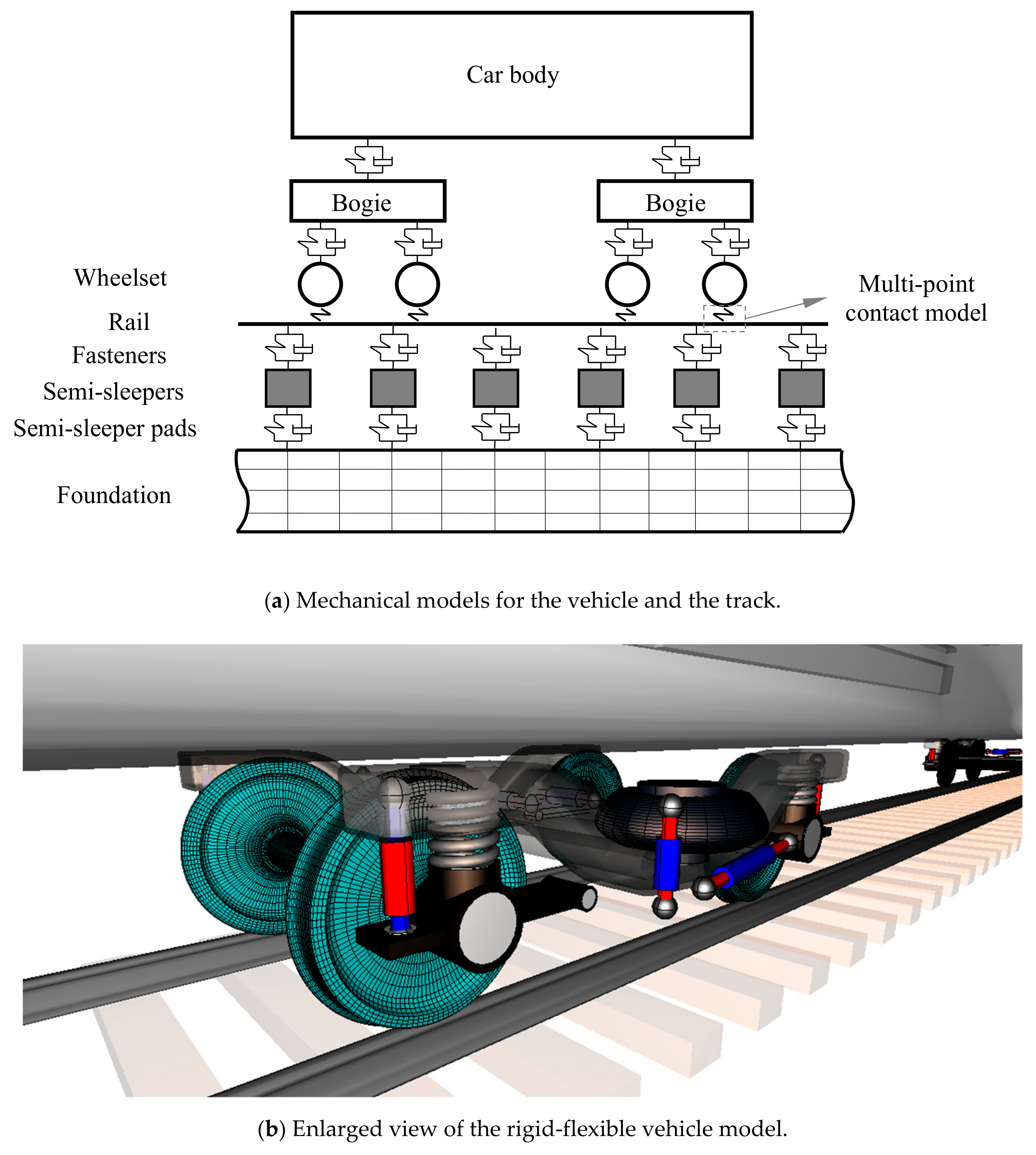
The vehicle–track system dynamics model consists of one high-speed electric multiple-unit carriage consisting of two rigid bogies and four elastic wheelsets running on a straight track (see Figure 3). The vehicle model of Chinese high-speed electric multiple units (EMUs)considers all translational and rotational degrees of freedom of the bodies. Each wheel of the wheelsets has a worn type tread, with the polygonal shape over the circumference at the center of the transverse profile modeled by a sinusoidal function to describe the harmonic wheel radius deviation from the nominal radius. Hence, the excitation caused by a polygonal wheel radius as a function of time Z(t) is defined by
where Δrn is the OOR amplitude of the nth-order polygonized wheel, n is the order of the polygonized wheel, v is the running speed, R is the nominal rolling radius, and ϕn is the phase angle. As the effect of phase shift is not considered in this paper, ϕn is set to zero. All the wheels of a train are assumed to be polygonal in this dynamic model.
The rails are considered as Timoshenko beams without irregularities. A special bushing-type force was used for the simulation of rail pads and fasteners, which connect with the under-rail base. The kinematic characteristics of the rails, rail pads, and fasteners correspond to those in the slab track finite element model. The Kik–Poitrowski model is adopted to calculate the vertical interaction forces within the wheel–rail contact patches, and tangent forces are calculated based on Kalker’s rolling contact theory [20]. Slab track parameters, such as the parameters of rails and their cross-sections, and the vertical and lateral stiffness of the track were consistent with the finite element track model built in ANSYS.
2.2. Dynamic Model of Track Structure
The ANSYS finite element analysis software allows a sufficiently accurate approximation of the track flexibility. Thus, a three-dimensional (3D) finite element model (FEM) of the slab track system was developed using ANSYS, with the slab track in Chinese high-speed railway lines as the object of study. The slab track parameters are presented in Table 1 [21]. Figure 4 illustrates the FEM of the slab track system, composed of the rail, rail fastenings, concrete slab layer, cement-asphalt (CA) layer, and support layer. The length of the slab track model is 6.45 m.
The standard CHN60 rail considered here is modeled using the ANSYS Solid45 3D solid finite elements and divided by a nonuniform mesh according to its nominal geometry. The rail ends are clamped. The loading area around the rail head is densely meshed with small elements (size ~2 cm), and larger elements are used for other components (largest ~6.5 cm). The rail fastenings are modeled as discrete linear elastic springs using the element type COMBIN 14 of ANSYS. This allows for longitudinal displacements, with the other degrees of freedom constrained. The concrete slab layer, CA layer, and support layer are all modeled using the ANSYS Solid185 3D solid finite elements and constructed from uniform meshes with a largest element size of 6.5 cm. The lower surface of the concrete slab layer is connected with the upper surface of the CA layer by coupled nodes. These nodes are also used as the connection between the lower surface of the CA layer and the upper surface of the support layer. The displacements and deformations are constrained in all three directions at the ends of the concrete slab layer and the bottom of the support layer. As the track structure is assumed to be symmetric with respect to the track centerline, only half of the structure is included in the model to reduce the computation time; this has a negligible influence on the precision of the simulation.
2.3. Wheel–Rail Force Transmission
The vertical wheel–rail interaction forces caused by polygonized wheels are determined by the vehicle–track coupled dynamics model, and then entered into the wheel–rail contact patch of the slab track FEM by point node load in the form of an array. This array is a 2D list (ti, Fi), where ti denotes the time with a mean time interval of 10−3 s and Fi is the vertical wheel–rail interaction force at time ti. The first few seconds of the UM simulations are not considered, as the system isin transient motion during this period.
A fixed-point excitation method is adopted for the loading process, that is, the load position does not move relative to the track, and the load value changes with time. A full transient dynamic method is adopted to analyze the track dynamics induced by polygonized wheels in the finite element model. The lateral wheel–rail forces are about 2–3 kN, much smaller than the vertical wheel–rail forces, so the effect of lateral forces is negligible.
2.4. Dynamic Equations of the Slab Track Finite Element System
Based on the Hamiltonian principle, the dynamic equation of the slab track system can be described as
where {δ}, {}, and {} are the generalized displacement, generalized velocity, and generalized acceleration of the track system, respectively; [M], [C], [K], and {F(t)}are the general mass matrices, damping matrices, stiffness matrices, and load vector of the track system, respectively, which are composed of element matrices that make up the track structure.
The dynamic responses of the track structure can be calculated using the Newmark-β implicit integration method as
where α and β can be calculated using the constant-average-acceleration method; in this study, α = 0.25 and β = 0.5. Δt is the time step used for the integration. The subscript n denotes tn = nΔt and n + 1 denotes tn+1 = tn + Δt.
Combining Equations (3) and (4), we obtain
Substituting Equations (5) and (6) into Equation (2) at time n + 1, we have
Simplifying Equation (7), {δn+1} can be defined as
where
We can then determine {δn+1} by solving Equation (8), and {} and {} can be calculated using Equations (5) and (6):
3. Results
The track dynamics as a result of the passage of a polygonal wheel at high speeds were determined using the finite element model described in Section 2 considering the three relevant parameters: Harmonic order, OOR amplitude, and running speed. According to the harmonic distributions of periodic polygonal wheels from field experiments in Chinese high-speed railway lines, taking the dominate polygons as an example, three separate cases were studied, and the simulation results are described below (see Table 2).
3.1. Case 1—Effect of OOR Amplitude on Track Dynamics
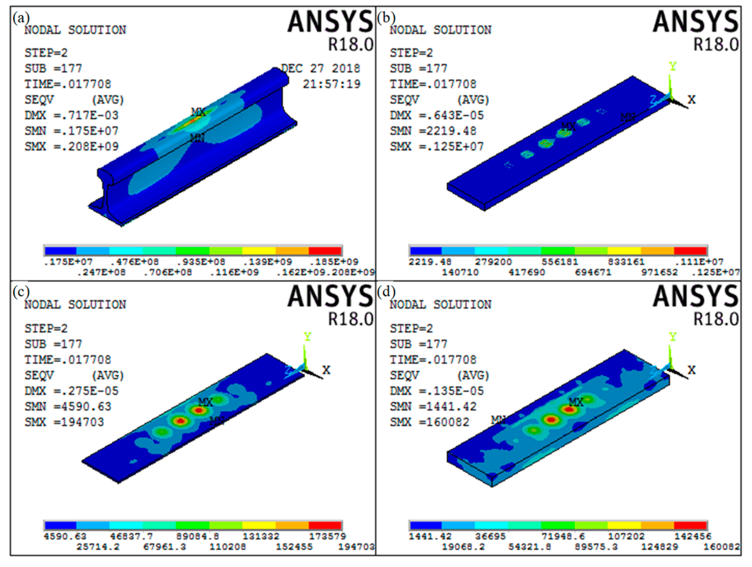
Figure 5 illustrates the von Mises equivalent stress in track components derived from the simulation for the case of a sixth-order polygonal wheel with an OOR amplitude of 0.09mm passing the midsection of the track at 300 km/h. In this figure, panel 1 depicts the von Mises equivalent stress in the rail between two adjacent rail fastenings with a constant spacing of 0.65 m. Panels 2, 3, and 4 illustrate the von Mises equivalent stress in the concrete slab, CA layer, and support layer, respectively. Figure 5 serves as an example of typical results obtained from the FE analysis.
It can be seen from Figure 5 that the peak von Mises equivalent stress in the rail occurs midway between two adjacent rail fastenings. Therefore, only the track responses from the middle cross-section between two rail fastenings are displayed; the position of the track fasteners is not displayed, due to space limitations. The track dynamics, namely, the stresses, displacements, and acceleration, were extracted at the time of maximum acceleration, and were measured from the FE-nodes between two adjacent rail fastenings on the slab, CA, and support top layer.
Five selected positions over a rail cross-section are denoted as A, B, C, D, and E in Figure 6. The responses of the rail vibration acceleration at a train speed of 300 km/h in Case 1 are illustrated in Figure 7. The time histories of the vertical acceleration at A, B, C, D, and E generally exhibit a sinusoidal shape, similar to the periodic radial deviation from the nominal radius.
Figure 8 shows the differences in acceleration, displacement, and von Mises equivalent stress between positions A–E on the rail cross-section. Figure 8a indicates that the vertical rail acceleration increases proportionately as the OOR amplitude of the polygonal wheel increases from 0.01 to 0.12 mm: The rail acceleration at A, B, C, D, and E for an OOR amplitude of 0.12mm is approximately 5.24, 6.94, 7.59, 6.73, and 4.49 times greater, respectively, than those for an OOR amplitude of 0.01 mm. This is because the impact load caused by polygonized wheels with an OOR amplitude of 0.12 mm can reach up to 120 kN, which is significant. This amount of load can increase the amplitude of acceleration, resulting in the collision of the edge of the polygon with the crown of the rail, so considerable attention should be paid to such wheels.
From Figure 8b, we can see that there are only small differences between the displacement responses at different positions on the rail cross-section. As the OOR amplitude varies from 0.01 to 0.12 mm, the displacement at A, B, C, D, and E increases by 52.26%, 52.32%, 52.43%, 52.52%, and 52.56%, respectively. There seems to be a linear relationship between the displacement and the OOR amplitude.
In Figure 8c, the same trend is observed: The stress at A, B, C, D, and E increases by 49.80%, 38.16%, 34.86%, 39.22%, and 47.02%, respectively, as the OOR amplitude of the polygonal wheel increases from 0.01 to 0.12 mm. Figure 8c also shows that, at a given OOR amplitude, the maximum von Mises equivalent stress occurs in the rail head, followed by that in the rail web; the minimum von Mises equivalent stress occurs at point D. Based on previous results, the OOR amplitude has more influence on the von Mises equivalent stress in the rail head than on those in the rail web and rail foot.
The corresponding dynamic responses of the rail-supporting structures—namely, the concrete slab layer, CA layer, and support layer—are shown in Figure 9. These results indicate that the displacement and von Mises equivalent stress in the concrete slab due to wheel polygons are far greater than those in the CA layer and support layer. As the OOR amplitude of the polygonal wheel increases from 0.01 to 0.12 mm, the displacement and von Mises equivalent stress in the concrete slab layer increase by 72.4% and 76.9%, respectively. By contrast, for the CA layer and support layer, a significant reduction in vibration can be observed compared to the slab layer. For example, the displacement in the CA layer and support layer does not exceed 0.4 mm, and, therefore, the von Mises equivalent stress does not exceed 0.23 MPa. Hence, vibrations in the rail reach the CA layer and support layer via the concrete slab layer in a greatly attenuated form.
3.2. Case 2—Effect of Harmonic Order on Track Dynamics
The time histories of vertical rail acceleration due to polygonal wheels with an OOR amplitude of 0.03 mm at 300 km/h for different harmonic orders are displayed in Figure 10. The relationship between the acceleration and the harmonic order exhibits the same trend as in Case 1.
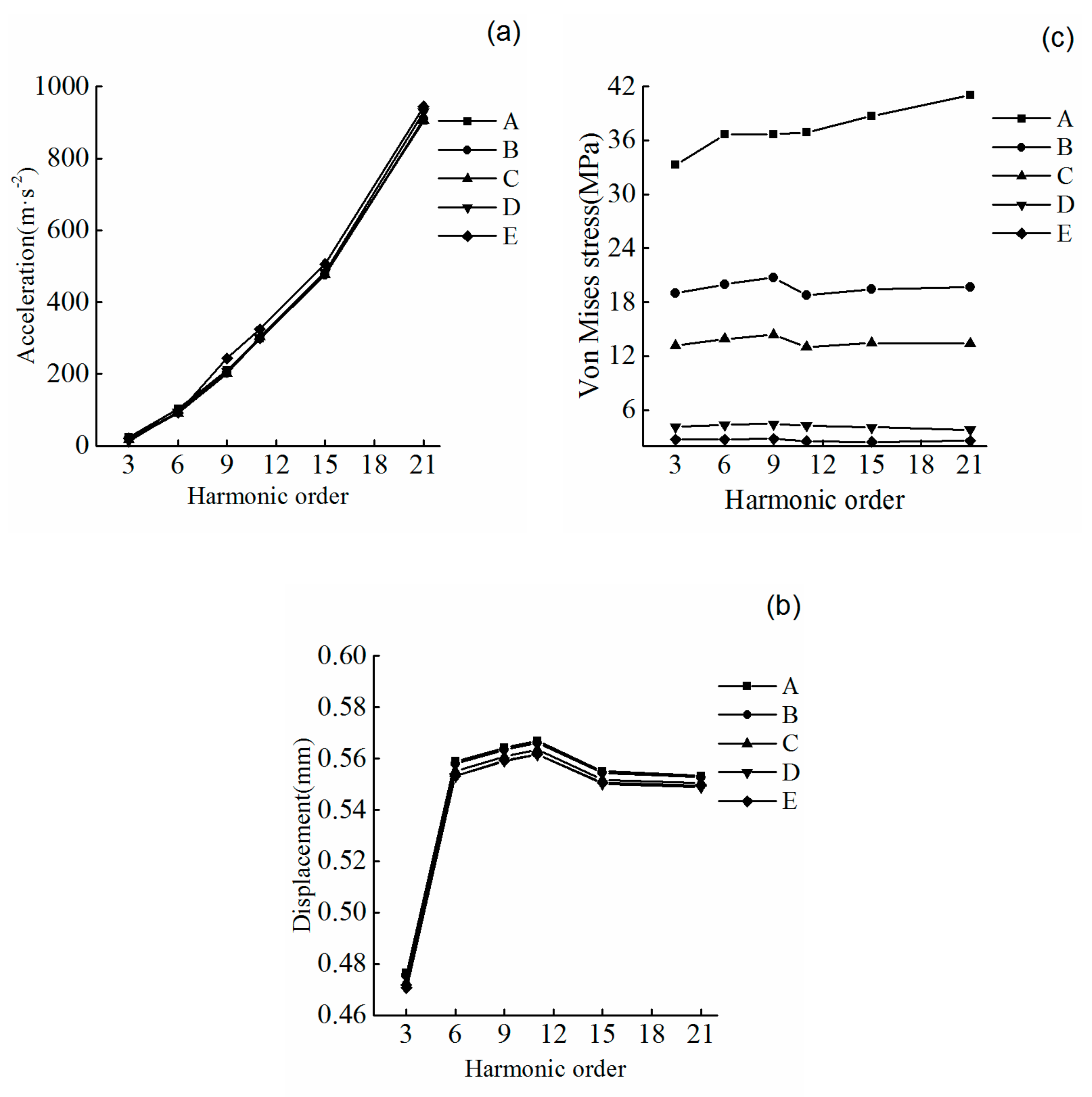
The numerically calculated dynamic responses of the rail in Case 2 are displayed in Figure 11. From Figure 11a, we see that the vibration acceleration of the rail increases linearly with the increase in the harmonic order of the wheel polygon. There are no significant differences in vibration acceleration between different parts of the rail cross-section. The influence of a higher-order polygonal wheel on rail acceleration is greater than that of a lower-order wheel. For instance, the acceleration caused by a 21st-order polygonal wheel is 18 times greater than that caused by a third-order wheel. The simulation results show a high degree of congruence compared to the acceleration response of the track system reported in Ref. [14].
It can be observed from Figure 11b that the same trend appears at each of the different positions. The vibration displacement in the rail increases as the harmonic order increases from three to nine, and increases most rapidly as the harmonic order increases from three to six. When a ninth-order polygonized wheel is travelling along the track at 300 km/h, the passing frequency is given by fn = v/λn = v/(2πR/n). When R = 0.46 m, fn = 259.5 Hz. According to the simulation results from tests of the slab track resonance mode, the low resonant frequency of the rail and the slab occurs at 286 Hz. This is very close to the passing frequency of 259.5 Hz. Hence, there is a significant increase in the ninth-order displacement, possibly because of an excitation of resonances in the rail and the slab. We conclude that modal properties of the track correlate with system parameters such as speed, polygon order, and wheel size. By contrast, the rail vibration displacement caused by wheel polygons with orders of 9 to 21 decreases with an increase in harmonic order. For a given harmonic order, the maximum vibration displacement is found in the rail head. In addition, there is little difference in vibration displacement between the rail web and rail foot.
It can be seen from Figure 11c that the von Mises equivalent stress increases linearly with an increase in harmonic order at node A. The von Mises stress of the other nodes remains almost constant. The maximum stress occurs in the rail head, followed by that in the rail web, and the minimum stress is found at point E for a given harmonic order. This implies that an increase in harmonic order has a greater influence on the stress in the rail head.
The corresponding dynamic responses of the rail-supporting structural components—namely, the concrete slab layer, CA layer, and support layer—are displayed in Figure 12. The results illustrate the effects of the harmonic order of a polygonal wheel on the dynamics in the supporting track components. The influence of harmonic order on the vibration displacement and von Mises equivalent stress in the concrete slab layer is significant. Both the displacement and the stress increase with an increase in harmonic order. For instance, the vibration displacement and von Mises equivalent stress in the concrete slab layer due to a third-order polygonal wheel are 0.0037 mm and 0.7603 MPa, respectively, whereas those resulting from a 21st-order polygonal wheel are 0.0064 mm and 1.1501 MPa, respectively. By contrast, the dynamic responses of the CA layer and support layer caused by polygonal wheels are far more subdued than those of the concrete slab layer. Hence, changes in the harmonic order of a polygonal wheel do not significantly influence the dynamic responses of the CA layer and support layer.
3.3. Case 3—Effect of Running Speed on Track Dynamics
The running speed has a significant influence on track dynamics. Figure 13 indicates the relationship between the vertical rail accelerations and running speed. The same trend as in Cases 1 and 2 is clearly evident.
The dynamic response of the rail in Case 3 is displayed in Figure 14. Figure 14a shows that when the running speed is 200 km/h, the vertical rail accelerations at positions A, B, C, D, and E are 42.76, 41.21, 39.91, 38.05, and 39.53 m/s2, respectively. When the running speed increases to 350 km/h, the vertical rail accelerations become 130.41, 125.65, 121.01, 120.22, and 120.81 m/s2, respectively. It can be concluded that an increase in running speed produces a proportional increase in the vertical rail acceleration.
Figure 14b shows that the vibration displacements of the rail at positions A, B, C, D, and E increase from 0.545, 0.544, 0.541, 0.539, and 0.539 mm at 200km/h to 0.5645, 0.5635, 0.5605, 0.5585, and 0.5584 mm at 350 km/h, respectively.
By contrast, Figure 14c indicates that the von Mises stresses at different positions in the rail increase slowly as the speed increases from 200 to 350 km/h. The simulation results show that running speed has a greater influence on the vertical rail vibration acceleration than on the vibration displacement and von Mises stress.
The corresponding dynamic responses of the track substructure are shown in Figure 15. The vibration displacements of the concrete slab layer, CA layer, and support layer are, respectively, approximately 0.00436, 0.00190, and 0.00094 mm at 200 km/h. When the speed increases to 350 km/h, the vibration displacements increase to 0.00551, 0.00260, and 0.00137 mm, increases of 26.38%, 36.84%, and 45.28%, respectively, over the corresponding values at 200 km/h. The von Mises equivalent stresses of the concrete slab layer, CA layer, and support layer increase from 0.83321, 0.13159, and 0.10736 MPa at 200km/h to approximately 0.96711, 0.17375, and 0.15748MPa at 350km/h, enhancements of 16.07%, 32.04%, and 46.68%, respectively. These results indicate that the von Mises equivalent stress and vibration displacement in the track substructure increase in proportion to the increase in running speed.
4. Discussion
We validated the simulation model under the same conditions as described by Xu P. and Cai C.B. [21]. We investigated the vertical vibration of the rail caused by China’s high-speed track spectrum at 300 km/h and compared it to results reported by Xu P. and Cai C.B. [21].The overall trends are consistent with the results reported by Xu P. and Cai C.B. [21].
However, there are several factors that may influence the simulation results: (1) Track irregularities were not considered in the vehicle–track coupled system dynamic model. Hence, the wheel–rail interactions input into the FE model may have been below their real values. (2) The vehicle–track system parameters—e.g., the stiffness and damping coefficient of the rail pad, CA layer, and support layer—in the simulation model may differ from their real values. (3) The dynamic displacements of the slab track vary as a function of time. There are phase differences between functions of acceleration and displacement in the rails and track layers because of the wheel–rail forces transmitted from the top layer to the bottom layer of the slab track in the form of stress waves. The displacement was extracted at the time of maximum rail acceleration, rather than at the time of maximum displacement.
According to the track dynamics derived from the FE simulations, wheel polygons have a greater effect on rail vibrations than on the concrete slab layer, CA layer, and support layer. In addition, compared to the characteristics of the rail dynamic displacement and stress, the rail acceleration magnitudes relative to both OOR amplitude and harmonic order are linear and stable. Furthermore, on the basis of the range and magnitude of the rail vibration accelerations, with the maximum acceleration reaching approximately 1200 m/s2 with 21st-order wheel polygons, it is recommended that sensors with a measurable range of 1500–2000 m/s2 be employed.
The results presented in this paper demonstrate that it is feasible to monitor wheel polygons in-service based on rail acceleration, displacement, or stress measurements. However, there are several factors that influence rail vibration, such as the type of track, train speed, and track irregularities. Hence, the outcomes of this study provide guidance for determining the most suitable sensor locations across and along the track for rail vibration measurements in order to have the greatest influence on the accuracy of wheel polygon identification.
5. Conclusions
Based on our analysis of the effects of wheel polygons on the dynamic behavior of high-speed railway tracks using a 3D FEM of the wheel–track coupled system, we conclude that the OOR amplitude and harmonic order of a wheel polygon have the greatest impact on the track dynamics. The following specific conclusions can be drawn:
- (1)
- Both the vibration displacement and the von Mises equivalent stress in structural components of the track increase with an increase in the OOR amplitude of a polygonized wheel. For a given OOR amplitude, the maximum vibration displacement and von Mises equivalent stress due to wheel polygons occur in the rail head.
- (2)
- The vibration displacement in the rail first increases and then decreases as the harmonic order increases from 3 to 21, with the displacement reaching a maximum for a ninth-order polygonized wheel. This is because of the excitation of the resonances of the rail and the slab at ~259.6 Hz. Special attention should be paid to such wheel polygons.
- (3)
- There are differences in the dynamic responses of the track caused by wheel polygons for train speeds of 200 to 350km/h, which implies that a change in train speed influences the displacement, acceleration, and stress in the track structure.
- (4)
- For Cases 1, 2, and 3 (defined in Section 3), the dynamic responses of the concrete slab layer, CA layer, and support layer decrease from top to bottom.Thus, significant vibration attenuation reduces the dynamic responses of the support layer and CA layer.
Further work is needed to develop a more complex model using ANSYSLS-DYNA, which will enable the analysis of wheel–rail rolling contact at high speeds. A new line of research must establish a non-track monitoring system to detect wheel defects on the basis of the dynamic response of the track caused by wheel polygons.
Author Contributions
Conceptualization, Y.S.; Formal analysis, X.Z.; Writing—review & editing, Y.D. and B.S.
Funding
This research was funded by National Natural Science Foundation of China grant number11372199, China Postdoctoral Science Foundation Funded Project grant number 2018M643521, and Natural Science Foundation of Hebei Province grant number E2019210152.
Acknowledgments
We would like to thank Editage (www.topeditsci.com) for English language editing.
Conflicts of Interest
The authors declare no conflict of interest.
Data Availability
The numerical simulation data used to support the findings of this study are available from the corresponding author upon request.
References
- Meywerk, M. Polygonalization of railway wheels. Arch. Appl. Mech. 1999, 69, 105–120. [Google Scholar] [CrossRef]
- Johansson, A. Out-of-round railway wheels—Assessment of wheel tread irregularities in train traffic. J. Sound Vib. 2006, 293, 795–806. [Google Scholar] [CrossRef]
- Dekker, H. Vibrational resonances of nonrigid vehicles: Polygonization and ripple patterns. Appl. Math. Model 2009, 33, 1349–1355. [Google Scholar] [CrossRef]
- Morys, B. Enlargement of out-of-round wheel profiles on high speed trains. J. Sound Vib. 1999, 227, 965–978. [Google Scholar] [CrossRef]
- Johansson, A.; Nielsen, J.C.O. Out-of-round railway wheels—Wheel-rail contact forces and track response derived from field tests and numerical simulations. Proc. Inst. Mech. Eng. FJ. Rail Rapid Transit 2003, 217, 135–146. [Google Scholar] [CrossRef]
- Kalousek, J.; Johnson, K.L. An investigation of short pitch wheel and rail corrugations on the Vancouver mass transit system. Proc. Inst. Mech. Eng. FJ. Rail Rapid Transit 1992, 206, 127–135. [Google Scholar] [CrossRef]
- Soua, B.; Pascal, J.P. Computation of the 3D Wear of the Wheels in a High Speed Bogie; Report; INRETS-LIN: Arcueil, France, 1995; pp. 21–40. [Google Scholar]
- Brommundt, E. A simple mechanism for the polygonalization of railway wheels by wear. Mech. Res. Commun. 1997, 24, 435–442. [Google Scholar] [CrossRef]
- Barke, D.W.; Chiu, W.K. A review of the effects of out-of-round wheels on track and vehicle components. Proc. Inst. Mech. Eng. FJ. Rail Rapid Transit 2005, 219, 151–175. [Google Scholar] [CrossRef]
- Popp, K.; Kaiser, I.; Kruse, H. System dynamics of railway vehicles and track. Arch. Appl. Mech. 2003, 72, 949–961. [Google Scholar]
- Luo, R.; Zeng, J.; Wu, P.B.; Dai, H.Y. Simulation and analysis of wheel out-of-roundness wear of high-speed train. J. China Railw. Soc. 2010, 32, 30–35. [Google Scholar]
- Wu, Y.; Du, X.; Zhang, H.; Wen, Z.F.; Jin, X.S. Experimental analysis of the mechanism of high-order polygonal wear of wheels of a high-speed train. J. Zhejiang Univ. Sci. A 2017, 18, 579–592. [Google Scholar] [CrossRef]
- Wang, Y.J.; Zeng, J.; Luo, R.; Wu, N. Wheel profile wear and wheel/rail contact geometric relation for a high-speed train. J. Vib. Shock 2014, 33, 45–50. [Google Scholar]
- Liu, X.; Zhai, W.M. Analysis of vertical dynamic wheel/rail interaction caused by polygonal wheels on high-speed trains. Wear 2014, 314, 282–290. [Google Scholar] [CrossRef]
- Wang, K. A Numerical Simulation of Wheel Polygonization of High-Speed Trains Based on Friction-Induced Vibration. Master’s Thesis, Southwest Jiaotong University, Chengdu, China, 2017. [Google Scholar]
- Chamorro, R.; Escalona, J.L.; González, M. An approach for modeling long flexible bodies with application to railroad dynamics. Multibody Syst. Dyn. 2011, 26, 135–152. [Google Scholar] [CrossRef]
- Zhou, X.J.; Xiao, Q.; Cheng, S.; Yang, Y.H. Influence of wheel harmonic wear of high speed train on creep characteristics of wheel-rail rolling contact under flexible track. China Railw. Sci. 2017, 38, 84–91. [Google Scholar]
- Dietz, S.; Hippmann, G.; Schupp, G. Interaction of vehicles and flexible tracks by co-simulation of multibody vehicle systems and finite element track models. Veh. Syst. Dyn. 2002, 37, 372–384. [Google Scholar] [CrossRef]
- Karl, P.; Holger, K.; Ingo, K. Vehicle-Track Dynamics in the Mid-Frequency Range. Veh. Syst. Dyn. 1999, 31, 423–464. [Google Scholar]
- Pieringer, A.; Kropp, W.; Nielsen, J.C.O. The influence of contact modelling on simulated wheel/rail interaction due to wheel flats. Wear 2014, 314, 273–281. [Google Scholar] [CrossRef] [Green Version]
- Xu, P.; Cai, C.B. Dynamic Analysis of longitudinally connected ballastless track on earth subgrade. J. Southwest Jiaotong Univ. 2011, 46, 189–194. [Google Scholar]
Figure 1.
Typical wheel polygons with different harmonic orders: (a) fourth-order; (b) 11th-order; and (c) 22nd-order.
Figure 1.
Typical wheel polygons with different harmonic orders: (a) fourth-order; (b) 11th-order; and (c) 22nd-order.

Figure 2.
Diagram of modeling workflow.

Figure 3.
Overview of the vehicle–track coupled system dynamic model.

Figure 4.
Illustration of 3D finite element (FE) model of slab track.

Figure 5.
Von Mises equivalent stresses in structural components of the track (Pa): (a) von Mises equivalent stress in the rail; (b) von Mises equivalent stressin the concrete slab layer; (c) von Mises equivalent stress in the CA layer; (d) von Mises equivalent stress in the support layer.
Figure 5.
Von Mises equivalent stresses in structural components of the track (Pa): (a) von Mises equivalent stress in the rail; (b) von Mises equivalent stressin the concrete slab layer; (c) von Mises equivalent stress in the CA layer; (d) von Mises equivalent stress in the support layer.

Figure 6.
Selected positions on rail cross-section.

Figure 7.
Time history of vertical vibration acceleration at points A–E on the rail for various out-of-roundness (OOR) amplitudes at a train speed of 300 km/h.
Figure 7.
Time history of vertical vibration acceleration at points A–E on the rail for various out-of-roundness (OOR) amplitudes at a train speed of 300 km/h.

Figure 8.
Effects of OOR amplitude on rail dynamics: (a) acceleration versus amplitude, (b) displacement versus amplitude, and (c) von Mises equivalent stress versus amplitude.
Figure 8.
Effects of OOR amplitude on rail dynamics: (a) acceleration versus amplitude, (b) displacement versus amplitude, and (c) von Mises equivalent stress versus amplitude.

Figure 9.
Effects of OOR amplitude on dynamics in rail-supporting structural components: (a) displacement and (b) von Mises equivalent stress.
Figure 9.
Effects of OOR amplitude on dynamics in rail-supporting structural components: (a) displacement and (b) von Mises equivalent stress.

Figure 10.
Time histories of vertical vibration acceleration at points A to E for various harmonic orders.
Figure 10.
Time histories of vertical vibration acceleration at points A to E for various harmonic orders.

Figure 11.
Effects of harmonic order on rail dynamics: (a) acceleration versus order, (b) displacement versus order, and (c) von Mises equivalent stress versus order.
Figure 11.
Effects of harmonic order on rail dynamics: (a) acceleration versus order, (b) displacement versus order, and (c) von Mises equivalent stress versus order.

Figure 12.
Effects of harmonic order on dynamics in rail-supporting structures: (a) displacement versus order and (b) von Mises equivalent stress versus order.
Figure 12.
Effects of harmonic order on dynamics in rail-supporting structures: (a) displacement versus order and (b) von Mises equivalent stress versus order.

Figure 13.
Time histories of vertical vibration acceleration vs. speed at points A to E.

Figure 14.
Effects of running speed on rail dynamics: (a) vibration acceleration versus running speed; (b) vibration displacement versus running speed and (c) von Mises equivalent stress versus running speed.
Figure 14.
Effects of running speed on rail dynamics: (a) vibration acceleration versus running speed; (b) vibration displacement versus running speed and (c) von Mises equivalent stress versus running speed.

Figure 15.
Effects of running speed on the dynamic behavior of supporting track components: (a) vibration displacement versus running speed and (b) von Mises equivalent stress versus running speed.
Figure 15.
Effects of running speed on the dynamic behavior of supporting track components: (a) vibration displacement versus running speed and (b) von Mises equivalent stress versus running speed.


Table 1.
Parameters of the slab ballast-less track.
| Component | Parameter | Value |
|---|---|---|
| CHN60 rail | Elastic modulus (N·m−2) | 2.1 × 10¹¹ |
| Poisson ratio | 0.3 | |
| Density (kg·m−3) | 7800 | |
| Rail fastenings | Elastic stiffness (MN·m−1) | 50 |
| Damping coefficient (kN·s/m) | 60 | |
| Longitudinal spacing(m) | 0.65 | |
| Concrete slab layer | Elastic modulus (N·m−2) | 3.9 × 10¹⁰ |
| Poisson ratio | 0.2 | |
| Length × width × thickness/m | 6.45 × 2.55 × 0.20 | |
| Density (kg·m−3) | 2500 | |
| CA layer | Elastic modulus (N·m−2) | 7.0 × 10⁹ |
| Poisson ratio | 0.167 | |
| Thickness (m) | 0.03 | |
| Density (kg·m−3) | 2590 | |
| Support layer | Elastic modulus (N·m−2) | 5.0 × 10⁹ |
| Poisson ratio | 0.2 | |
| Width × thickness (m) | 3.25 × 0.3 | |
| Density (kg·m−3) | 2500 |
Table 2.
Simulation cases.
| Case | OOR Amplitude (mm) | Harmonic Order | Running Speed (km·h−1) |
|---|---|---|---|
| Case 1: Effect of OOR amplitude on track dynamics | 0.01–0.12 | 6 | 300 |
| Case 2: Effect of harmonic order on track dynamics | 0.03 | 3–21 | 300 |
| Case 3: Effect of running speed on track dynamics | 0.03 | 6 | 200–350 |
© 2019 by the authors. Licensee MDPI, Basel, Switzerland. This article is an open access article distributed under the terms and conditions of the Creative Commons Attribution (CC BY) license (http://creativecommons.org/licenses/by/4.0/).
Share and Cite
MDPI and ACS Style
Song, Y.; Du, Y.; Zhang, X.; Sun, B. Evaluating the Effect of Wheel Polygons on Dynamic Track Performance in High-Speed Railway Systems Using Co-Simulation Analysis. Appl. Sci. 2019, 9, 4165. https://doi.org/10.3390/app9194165
AMA Style
Song Y, Du Y, Zhang X, Sun B. Evaluating the Effect of Wheel Polygons on Dynamic Track Performance in High-Speed Railway Systems Using Co-Simulation Analysis. Applied Sciences. 2019; 9(19):4165. https://doi.org/10.3390/app9194165
Chicago/Turabian StyleSong, Ying, Yanliang Du, Xuemei Zhang, and Baochen Sun. 2019. "Evaluating the Effect of Wheel Polygons on Dynamic Track Performance in High-Speed Railway Systems Using Co-Simulation Analysis" Applied Sciences 9, no. 19: 4165. https://doi.org/10.3390/app9194165
Note that from the first issue of 2016, this journal uses article numbers instead of page numbers. See further details here.