Article

A Damage Model Reflecting the Interaction between Delamination and Intralaminar Crack for Failure Analysis of FRP Laminates

1
Faculty of Mechanics, Kim Il Sung University, Pyongyang 950003, D.P.R. Korea
2
Faculty of Mechanical Engineering, Kimchaek University of Technology, Pyongyang 950003, D.P.R. Korea
3
College of Aerospace and Civil Engineering, Harbin Engineering University, Harbin 150001, China
4
Information Center, Kim Il Sung University, Pyongyang 950003, D.P.R. Korea
*
Author to whom correspondence should be addressed.
Appl. Sci. 2019, 9(2), 314; https://doi.org/10.3390/app9020314
Submission received: 3 December 2018 / Revised: 27 December 2018 / Accepted: 2 January 2019 / Published: 16 January 2019

Abstract

:
In this paper, a progressive damage model reflecting the interaction between delamination and intralaminar crack is developed to predict fracture behaviors and the ultimate load-bearing ability of the fiber-reinforced polymer laminates subject to quasi-static load. Initiation and evolution of intralaminar crack in composites are modeled using a continuum damage mechanics model, which has the capability to reliably predict the discrete crack direction by introducing the crack direction parameter while analyzing the multi-failure of FRP composites. Delamination is modeled using a cohesive zone method with the mixed bilinear law. When the continuum damage model and cohesive zone model are used together, the interactive behavior between multiple failure mechanisms such as delamination induced by matrix cracking often seen in the failure of composite laminates is not generally captured. Interaction between delamination and intralaminar crack in FRP composite structures is investigated in detail and reflected in a finite element analysis in order to eliminate the drawbacks of using both models together. Good agreements between numerical results and experimental data are obtained.

1. Introduction

Fiber-reinforced polymer (FRP) laminates are widely used in aerospace, automotive, medical components, and sports equipment, due to their advantages. The transverse loading and low-velocity impact of the fiber-reinforced polymer laminates are the common loading conditions of the composite structures. The complexity of failure processes involving intra- and inter-laminar damage in composite laminates needs reliable failure theories and a damage evolution mechanism. To determine the fracture behavior in engineering structures under quasi-static or impact load, the studies on a reasonable numerical analysis method are mainstream in computational fracture mechanics.
Various intralaminar damage mechanisms have been proposed and demonstrated in the composite structures. The traditional fracture mechanics using crack propagation theory have been developed and matured well to solve these issues, but it is difficult to explain the complex failure process of the composites such as kinking and crushing. The first-ply failure model, in which all material properties are set to zero once a prescribed failure criterion is satisfied, are proposed in the numerical simulation, but the initiation of damage does not cause instantaneous failure of the entire structure, because of the complex fracture nature of laminated composites [1,2]. The cohesive zone model (CZM) was recently used for simulating intralaminar failure [3,4], but the CZM approach has a shortcoming; it is difficult for CZM to describe arbitrary matrix cracks in composites. Continuous damage mechanics (CDM) of composite materials stands on its own as a mature field solidly having a variety of analytical and computational methodologies associated with it [5,6,7,8]. CDM theory was the first applied to study the creep rupture of materials [9], and the progressive damage failure analysis based on CDM has been widely employed to predict the damage initiation and evolution of composites. Maimí et al. [10,11] proposed a continuum damage model for the prediction of the intralaminar failure mechanisms in composite laminates, and Chen et al. [12] proposed a combined elastoplastic damage model for the progressive failure analysis of composite materials. Nuismer et al. [13] adopted the shear lag model and defined transverse and shear damage as an internal state variable representing the lamina damage state directly. Salavatian et al. [14] developed the improved shear damage evolution model for fiber-reinforced laminates and considered the effect of matrix cracks on transverse and shear damage evolution. Yun et al. [15] proposed the CDM model with the introduction of the crack direction parameter, which has the capability to predict the initiation and direction of crack propagation.
Interlaminar delamination has been widely studied, where agreement between models and experiment is common [16,17,18,19,20]. The delamination simulation of composites using the finite element method (FEM) has been generally performed by the CZM approach. The CZM approach does not require remeshing for crack propagation and can predict both the initiation and progression of delamination. Dugdale [21] first proposed CZM, and Barenblatt [22] introduced an idea of cohesive forces on a molecular scale. Rose et al. [23] proposed the exponential cohesive zone model, and Hillerborg et al. [24] introduced the bilinear cohesive law. The bilinear hardening traction-separation relationship is still a basic element in several widely-used cohesive laws for the delamination analysis [25,26,27,28,29,30,31,32].
Composite failure is characterized by a strong interaction of intralaminar failure and interlaminar delamination. Maimí [33] presented the damage model considering the relation between matrix crack density and delamination in order to predict the propagation of matrix cracking and delamination in laminated composites. Rebière [34] proposed the variational approach reflecting the initiation of local delamination near the tips of transverse cracks in 90° layers and longitudinal cracks in 0° layers parallel to the loading. Conventionally, these intra- and inter-laminar failure mechanisms have been treated separately in fracture finite element analysis of composites, but recently, these interactions of multiple damage modes have been studied by several researchers [35]. Mark et al. [36] simulated the interaction of intra- and inter-laminar damage for composite laminates using CZM and CDM, respectively, and compared with the experiment. It was concluded that CZM cannot be widely applied to a variety of problems because of prescribing the damage-evolution path and CDM delays the delamination initiation significantly and underpredicts the final delamination crack length. An approach, which combines the floating node method with the VCCT, is proposed to simulate delamination migration in cross-ply tape laminates [37]. Ullah et al. [3,38] developed 2D FE models to simulate some modes of inter- and intra-laminar cracks and their interaction by employing cohesive zone elements (CZEs) in the intralaminar failure; this has the disadvantage that they are only available for a pre-known damage-evolution path. The phantom node method for matrix cracking and CZM for delamination are used for failure analysis of composite laminates [39]. CZM in conjunction with the extended finite element method (XFEM) cannot capture the load transfer between cohesive interfaces and the solid elements when crack bifurcation or coalescence occurs [40]. An extended cohesive damage model is introduced by combining XFEM and CZM for simulating multicrack propagation in fiber composites [41,42]; XFEM is very effective for treating cracks to even multiple levels, but it has some shortcomings, such as difficulty with 3D crack propagation and high computational cost [43]. The phase field model combined with CZM [44] and the XFEM approach coupled with CDM [45,46] have also been proposed to simulate the interaction of delamination and intralaminar crack. CZM and CDM are used together to predict the damage caused by low velocity impact in carbon-epoxy [ 0 4 90 4 ] s laminates [47]. The method of using CDM for the intralaminar failure and using CZM for the interlaminar delamination of composites is still extensively used in the laminated composite damage analysis [48], but it has led to the loss of coupling information for simulating multiple damage modes and also results in inaccurate prediction of crack paths [3]. CZM in conjunction with CDM cannot capture the high stresses at the tip of the transverse crack in the numerical simulation, for the elements where the transverse crack is predicted soften without being able to capture the stress field accurately at the interface, and this approach also does not explicitly represent the kinematics of the cracks [37,49]. The interaction between matrix cracks and delaminations in composite laminates has been investigated experimentally or theoretically in the previous studies, but the drawbacks of not being able to reflect interaction between several failure mechanisms, such as delamination due to matrix cracking, have not yet been remedied in the approaches of using CDM and CZM together. A few studies have been performed to solve the issues concerning the damage interaction for failure simulation of FRP laminates. In a word, there is no effective progressive damage model both capturing all multi-damage modes together and reflecting the interaction between the complex failure mechanisms for the FRP composites.
This work presents a novel approach for modeling the interaction of delamination and intralaminar crack in composite materials with a polymeric matrix reinforced with carbon fibers subject to quasi-static load. An effective finite element model based on the coupling of both approaches of CDM and CZM is proposed, which can simulate the progressive damage failure and interaction between damage mechanisms. Several significant steps are developed to simulate fully the failure of FRP laminates under the quasi-static load. The progressive damage analysis provides the ultimate strength prediction and multiple failure mechanisms of the composite laminates.

2. Mechanics Model

A constitutive model based on the CDM theory, which can also consider the propagation path of discrete crack for intralaminar failure, is considered, while CZM with the bilinear law is used for modeling the interlaminar delamination. In order to consider the interaction, degradation of the interlaminar critical fracture energy release rate following the intralaminar fiber and matrix failure is considered. All processes of failure are investigated based on fracture energy dissipation. The mechanics theories presented in Section 2.1 and Section 2.2 are repetitive of prior works in various aspects, but they are briefly described to help the understanding of the interaction model in Section 2.3. In this section, the theoretical model was researched, while employment in commercial finite element method software is detailed in the next section.

2.1. Material Damage Model for Intralaminar Failure

In this section, the advanced CDM model, which can reflect the direction of matrix crack, is introduced. The constitutive model and damage variables are briefly summarized here, and for details for comprehensive understanding, the work in [15] can be referenced. The present damage model, in which the crack direction parameter is used as a major factor along with the damage variable, has a good ability to predict the propagation of the discrete crack well in the composites’ failure simulation.
Three types of matrix crack were mainly studied to predict the failure behavior of FRP laminates by CDM: transverse crack, longitudinal crack, and delamination [49,50]. Many researchers focus on the transverse failure in the 0° layer and the longitudinal failure in the 90° layer, but the general cases such as angled matrix failure are less studied by the anisotropic damage model. In actual engineering applications, matrix cracks are properly angled with the mid-plane under a complex loading state [51,52], but are almost parallel to the fiber in every layer, so the matrix cracks parallel to the fiber are only considered in this work. An anisotropic damage model that reflects various kinds of matrix cracks and their interaction is presented here.
In damaged FRP materials, the complementary free energy density is given as follows.
ψ = σ 11 2 2 E 1 ( 1 d 1 ) + 1 E 2 σ 22 2 1 d 2 + σ 33 2 1 d 3 ν 12 E 1 ( σ 22 + σ 33 ) σ 11 ν 23 E 2 σ 22 σ 33 + σ 12 2 2 G 12 ( 1 d 4 ) + σ 23 2 2 G 23 ( 1 d 5 ) + σ 31 2 2 G 12 ( 1 d 6 )
where d i , i = 1 , 2 , 3 are the damage variables for tension or compression failure modes, while d i , i = 4 , 5 , 6 are the damage variables for shear failure modes. According to the second principle of thermodynamics for ensuring positive dissipation of mechanical energy:
ε = ψ σ = S : σ
where ε , σ , and S are the strain tensor, stress tensor, and flexibility operator, respectively.
S = 2 ψ σ σ = 1 E 1 ( 1 d 1 ) ν 12 E 1 ν 12 E 1 0 0 0 1 E 2 ( 1 d 2 ) ν 23 E 2 0 0 0 1 E 2 ( 1 d 3 ) 0 0 0 1 G 12 ( 1 d 4 ) 0 0 s y m m . 1 G 23 ( 1 d 5 ) 0 1 G 12 ( 1 d 6 )
Among six damage variables, two variables are independent, and their relationships are as follows:
1 d 4 = ( 1 d 1 ) ( 1 d 2 ) , 1 d 5 = ( 1 d 2 ) ( 1 d 3 ) , 1 d 6 = ( 1 d 3 ) ( 1 d 1 )
Damage variable d 1 is associated with fiber and matrix damage in the fiber direction, while d 2 and d 3 are associated with discrete matrix cracks for tension failure. Based on the bilinear softening law, the individual damage variables are determined as follows.
d = 0 δ e < δ e * δ e f ( δ e δ e * ) δ e ( δ e f δ e * ) δ e * δ e < δ e f 1 δ e δ e f
where δ e * is the equivalent displacement at the damage initiation and δ e f is the equivalent displacement when the material reaches its ultimate strength.
Three coordinates are introduced as shown in Figure 1: global Cartesian coordinates ( x ¯ , y ¯ , z ¯ ) , layer coordinates ( x , y , z ) , and local element coordinates ( x , y , z ) . It is mentioned that superscripts “−” and “′” refer to the global Cartesian coordinates and local element coordinates respectively, and layer coordinates corresponded to no superscript. The global Cartesian coordinates and layer coordinates are well known in the mechanics of composite materials and need not be described in more detail. In the local element coordinate system, the x -axis is set as the fiber direction, the y -axis as the direction perpendicular to the crack surface, and the z -axis as the direction perpendicular to the fiber and laying on the crack surface. In Figure 1, the y-, y -, z-, and z -axes are all placed on a plane perpendicular to the fiber. It is considered that the crack surface is parallel to the fiber and has angle α with the y-axis of layer coordinates, where the angle α characterizes the normal direction of the crack surface and is referred to as the crack direction parameter. The crack direction parameter α is defined as follows:
α = a r c t a n σ e σ y τ y z , σ e = σ y + σ z 2 + σ y σ z 2 2 + τ y z 2
The crack direction parameter, which is determined by the stress components in the y z plane, is introduced as a major factor with the damage variable for damage propagation and failure analysis.
For matrix tension damage, the damage variable d 3 is equal to zero, and then, the flexibility matrix S in local coordinates is as follows.
S = 1 E 1 ( 1 d 1 ) ν 12 E 1 ν 12 E 1 0 0 0 1 E 2 ( 1 d 2 ) ν 23 E 2 0 0 0 1 E 2 0 0 0 1 G 12 ( 1 d 4 ) 0 0 s y m m . 1 G 23 ( 1 d 5 ) 0 1 G 12 ( 1 d 6 )
From Equation (4), d 4 = 1 ( 1 d 1 ) ( 1 d 2 ) , d 5 = d 2 , d 6 = d 1 .
In three coordinates, the elastic stress-strain relations can be written as follows.
ε = S · σ , ε = S · σ = T · S · T T · σ , ε ¯ = S ¯ · σ ¯ = R · T · S · T T · R T · σ ¯ = R 0 · S · R 0 T · σ ¯
where σ ¯ , σ , σ are the stress tensor in global coordinates, layer coordinates, and local coordinates, respectively, ε ¯ , ε , ε are strain tensor in global coordinates, layer coordinates, and local coordinates, respectively, S ¯ , S , S are flexibility tensor in global coordinates, layer coordinates, and local coordinates, respectively, and R and T are the transform matrix from the layer coordinate system to global coordinate system and that from the local coordinate system to the layer coordinate system, respectively.
The global transform matrix is as follows: R 0 = R · T . Since the crack direction parameter is entered into the matrix T , transform matrix T is varied with the crack direction. The constitutive tensor is transformed with the varying of T in the element according to Equation (8), and so, the transformed flexibility tensor S contains the information of the discrete crack direction. This means that the CDM model becomes able to reflect the state of matrix cracking. The matrix stiffness matrix is given as follows:
C ¯ = S ¯ 1
For the matrix compression damage mechanism, the damage variable d 2 is considered to be equal with damage variable d 3 , the local coordinates are same as the layer coordinates and the transform matrix R 0 becomes R in Equation (8) by altering matrix T into the unit matrix. This does mean that the local coordinates are separately defined under matrix tension and matrix compression.
The damage initiation criteria, equivalent stress, and equivalent displacement for the progressive damage, the characteristic length, and the expressions for energy dissipation could be referenced in [15]. It is mentioned that the introduction of the characteristic length can eliminate the mesh dependency of the simulation results by CDM [1].

2.2. Modeling of Mixed-Mode Delamination

The simulation of delamination using the finite element method (FEM) is normally performed by means of CZM. Several concepts and modifications of CZM approach were suggested by many researchers over the past two decades [53,54]. Here, we will use the framework developed by Alfano and Crisfield [50]. They developed zero-thickness cohesive zone elements, which do not represent physical material, but represent material resistance when pulled apart. The nonlinear fracture process is governed by the bilinear traction-separation law in the cohesive zone. A schematic mixed-mode dominated by the bilinear traction-separation law is shown in Figure 2. The Mode I-dominated law is applicable when cohesive separation is dominated by the displacement jump normal to the interface, while the Mode II-dominated law is applicable when cohesive separation is dominated by shear displacement. The mixed mode bilinear cohesive law is used when the separation of material interfaces depends on both the normal and tangential components of displacement jumps.

2.2.1. Mixed Mode Traction-Separation Law

The normal and tangential components of the traction are expressed as:
T n = K n δ n ( 1 D m ) , T t = K t δ t ( 1 D m )
where T n and T t are the normal and tangential traction, respectively, δ n and δ t are the normal and tangential displacement separation, respectively, K n and K t are the normal and tangential cohesive stiffness, respectively, and D m is the damage parameter.

2.2.2. Mixed Mode Damage Model

The non-dimensional effective displacement jump parameter λ for mixed mode fracture is defined as:
λ = δ n δ n c 2 + β 2 δ t δ t c 2
where δ n c and δ t c are the normal and tangential displacement separation at the completion of debonding, respectively, and β is the non-dimensional parameter, which assigns different weights to the tangential and normal displacement jumps, defined by:
λ c r = δ n * δ n c = β δ t * δ t c
where δ n * and δ t * are the displacement separation at the maximum normal and tangential cohesive traction, respectively, and λ c r is the value of λ at which effective traction is maximum. It is noted that the parameter β is not used in [50], and in this paper, it is set to one. The mixed mode damage variable D m is given by:
D m = 0 λ λ c r λ λ c r λ ( 1 λ c r ) λ c r λ < 1 1 λ > 1

2.2.3. Fracture Mechanics-Based Criterion

The normal and tangential displacement separations δ n c and δ t c in Equation (11) are generally determined by Mode I and Mode II critical energy release rates G I c and G I I c . The area under the traction-separation law represents the energy released during the failure process, and a schematic representation is shown in Figure 2. The fracture mechanics-based power law criteria [55] established in terms of the energy release rates under mixed-mode loading are used in the paper.
G I G I c 2 + G I I G I I c 2 = 1
where G I and G I I are the energy release rates in Modes I and II, respectively. The degradation of the critical energy release rate of CZEs for the FEM modeling are presented in the following sections.

2.3. Interaction between Delamination and Intralaminar Failure

In this work, intralaminar failure is analyzed by the CDM model, which has the capability to predict the path of matrix crack propagation reliably, while interlaminar failure is analyzed by CZM. In general, the use of CZM together with CDM can lead to less accurate solutions for the failure of composite laminates, for it cannot capture the load transfer between cohesive interfaces and the solid elements when matrix cracks reach an interface [37,49]. Many research works pointed out these problems in theoretical analysis or simulation results by using CDM and CZM together. To overcome the difficulties in the simulation of the interaction between failure mechanisms, researchers proposed fully-three-dimensional CDM models that represent the delamination, as well as intralaminar failure [15,49,56]. However, these approaches, for which delamination is considered to be same as a matrix cracking and is simulated by CDM, could not eliminate the influence of element size through-thickness on the numerical simulation result for delamination growth. The approaches, which only use CZM to represent both intralaminar and interlaminar failure mechanisms, were proposed by [3,35,57], but it is impossible for CZM to describe the non-prescribed matrix crack path in composites. As the matrix crack path is not known a priori in the simulation for general engineering applications, these approaches are not recommended to solve the practical problems. In [58], the approach using spring elements was also proposed to incorporate the interaction between the matrix cracks and the delamination.
A significant energy interaction exists between interfacial delamination and intralaminar failure for the FE model. Once matrix fracture occurs at an element, the element has lost its cohesive traction and can be expressed as a state only with fiber. The interlaminar element adjacent to this intralaminar element can be considered as delamination failure, because there is no cohesive traction of this interlaminar element after that. When the matrix is damaged at the intralaminar element adjacent to the interlaminar element, it is used for tension and shear damage at the adjacent interface element. It shows that the energy release process in the intralaminar element is not independent of the adjacent interlaminar element. Therefore, it is necessary to set the relationship of the energy interaction between the adjacent solid element and the interface element. If this relationship of the energy interaction is not set, the fractured or damaged elements cannot induce the interface element damage. For this reason, it was difficult to predict the correct path of multicracks before.
When the element adjacent to CZE is damaged, the critical energy release rate of CZE suggested in Equation (14) is reduced with the following linear relationship for the finite element modeling.
G I c d = G I c [ 1 max { D 1 , D 2 } ] , G I I c d = G I I c [ 1 max { D 1 , D 2 } ]
where G I c d , G I I c d are the Mode I and II critical energy release rates of CZE, respectively after intralaminar damage, and D 1 , D 2 are the matrix damage variables at two intralaminar elements adjacent to a given CZE, which are given by Equation (5). This means that critical energy release rates of CZEs are not independent of matrix damage of the adjacent solid elements and vary with their damage variable, that is the CZEs are easily damaged with a high matrix damage level.
Studies to describe the close relationship between delamination and intralaminar crack were also proposed in the past. Maimí et al. [33] investigated the relationship between the rate of delamination and the crack density in the mesomodel defined by the ply level by employing the stochastic method and suggested that the rate of delamination increases as the crack density increases. They pointed out that the damage variable of the representative element increased with transverse matrix crack density and that the delamination can be easily triggered by increasing the crack density. However, the direct relationship between the damage variable and the rate of delamination was not proposed, and the discrete crack was excluded from consideration. In this work, the linear relationship between the damage variable of solid elements and critical energy release rates of CZEs is constructed in order to make the relationship that can be easily used in the finite element analysis process, inheriting the conceptual basis given by Maimí.

3. Finite Element Modeling

The approach based on the finite element method is the most suitable tool and is capable of simulating the failure process of the composite structure under complex loads. The material property degradation method using CDM and the cohesive zone method are implemented in FE modeling to characterize the initiation, evolution, and interaction of the damage modes for the failure analysis of composite structures.
A meso-level FE model is developed in the commercial FE package ANSYS to predict the progressive failure of intralaminar damage, interlaminar damage, and their interaction with the laminate composites. Composite layers are meshed with structural solid elements, and the interface between two layers is modeled with the cohesive zone elements in the ANSYS element library. The approach based on the coupling of continuum damage mechanics and the cohesive zone method is implemented by using ANSYS Parameter Design Language (APDL). The linear orthotropic material property is used before damage initiation, while the anisotropic elastic (ANEL) modulus matrix is used during damage evolution. Damage variables, crack direction parameters, the transform matrix, and the damaged stiffness matrix are all calculated using the element table and updated with the time step after the solution. Matrix multiplication and invert operations are performed using ANSYS matrix process functions.
When simulating FPR composites failure, Hashin criteria and equivalent damage scale-based criteria are used for judging the damage initiation and evolution, respectively. Once a layer element is damaged, the damage variable and crack direction parameter are calculated at this element, and then, stiffness degradation is performed according to the damage evolution model based on the CDM theory. This stiffness degradation of layer elements leads to the stress redistribution and stress concentration on neighboring layer elements. The damage variable calculations are performed at all damaged elements under this stress concentration, and this process is repeated continuously under the same load level until there is no variation of the damage variable distribution of the element. Comparison of the damage variable distribution between two sequence processes is performed to guarantee the gradual increase of the damage variable at every element for every process.
The concept of the newly-damaged element set is applied to the calculation of the crack direction parameter. The newly-damaged element set contains the element in which the damage variable at the current load step is greater than the one at the previous load step, and the damage variable at the previous load step is equal to zero. That is, in all elements of this set, the damage variables would have variations at the current time step, and the damage variables are equal to zero at the previous time step. To save the computational cost, the calculation of the crack direction parameter is only performed in the newly-damaged element set.
On the other hand, the calculation of the damage level is also performed for the CZEs between two layers to predict the delamination evolution. Once the intralaminar elements adjacent to a CZE have failed, the degradation of critical energy release rates is performed according to Equation (15) for the CZEs. Then, the load increases, and the iterative process repeats until a final catastrophic failure occurs in the composite laminates.
Convergence difficulties are often seen in numerical simulation for fracture problems of composites by using the material property degradation method of CDM or the traction-separation law of CZM. Although the energy stabilization method helps enhance the numerical convergence, it could not completely overcome the convergence difficulties. To alleviate these difficulties, a viscous damage variable is introduced in this work.
D r ( t n ) = η η + Δ t n D r ( t n 1 ) + Δ t n η + Δ t n D ( t n )
where D r ( t n ) , D r ( t n 1 ) are the regular damage variables at the current time step t n and previous time step t n 1 , respectively, D ( t n ) is the damage variables at the current time step t n directly obtained from Equation (5), Δ t n is the time step ( = t n t n 1 ), and η is a viscous coefficient.
The viscous coefficient helps stabilize the solution system for fracture simulation of FRP composites. Lapczyk [59] suggested that a value of the viscous coefficient that is small compared to the time increment does not compromise the results significantly. In this work, the viscous coefficient η is set to 0.5 Δ t . In every time step, stiffness degradation is performed at the elements for which the difference between regular damage variables Δ D r ( t n ) ( = D r ( t n ) D r ( t n 1 ) ) is greater than zero. To reduce simulation time, the former material numbers are still used, and material properties are altered at the already damaged elements for which the damage variable differences Δ D r ( t n ) are bigger than zero. New material numbers are only assigned at the newly-damaged elements for which the differences Δ D r ( t n ) are bigger than zero, and the damage variable at the previous time step is equal to zero. The added nonlinear material properties are deleted, and the initial properties are recovered in the elements, which are not fully damaged, but for which the damage evolution had stopped.

4. Results and Discussion

The validity of the proposed approach reflecting the interaction between delamination and intralaminar crack is checked by two numerical simulations with delamination due to matrix crack in this section.

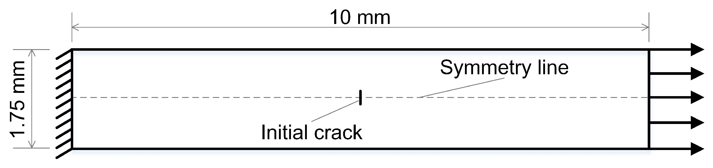
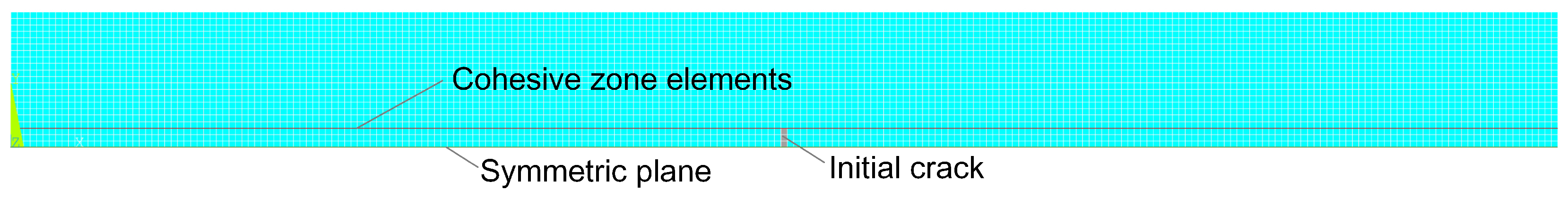
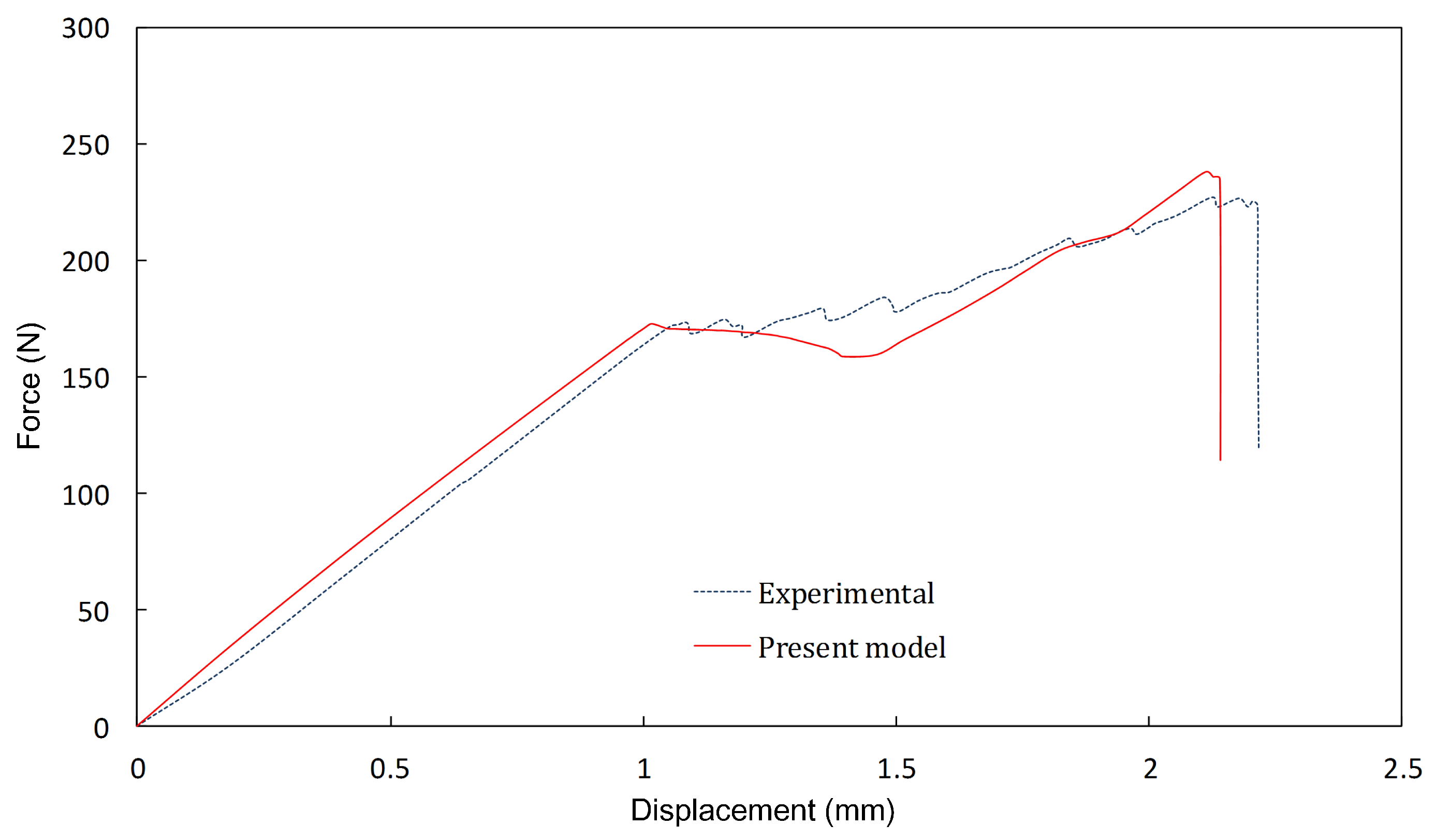
4.1. Unidirectional Specimen with a Central Cut under Tension

The unidirectional specimen with a cut across the width of one central ply loaded in tension was considered. In order to observe the delamination propagation deriving from the matrix crack, measurements on remote stresses (the ratio between the load and the cross-section area) were performed [49]. The geometry and the loading conditions are shown in Figure 3. The material properties of 977-2 HTS [ 0 7 o ] CFRP composite laminates are as follows: Young’s modulus E 1 = 144 GPa, E 2 = 7.5 GPa, shear modulus G 12 = 5.03 GPa, Poisson’s ratio ν 12 = 0.29 , ν 23 = 0.50 , tensile strength X T = 2290 MPa, Y T = 47 MPa, shear strength S = 67 MPa, and fracture energy G s = 1.55 N/mm. In this problem, Mode II shear failure dominates in interlaminar failure, and delamination growth is promoted by the pre-given initial matrix crack before the overall fracture due to fiber tension breaking of other layers.
A finite element mesh is shown in Figure 4, where half of the geometry (0.85 mm height) is chosen for the simulation because of the symmetry of the problem, and the plane strain state is considered with displacement control. The red line represents cohesive zone elements and is only assigned to the down interface in the figure (middle part in the whole area), for the interlaminar damage only occurred in this interface. The initial crack was formed by the killing element technique here. From the deformed shape showed in Figure 5, it can be found that the delamination by shear occurred in the interface between the two layers through nodal separation; of course, this is not intuitive, as in the Mode I failure. After the delamination had grown to some extent, the fiber damage initiated and evoluted in the outer plies.
The remote stress-displacement curve predicted by our approach is shown in Figure 6. The remote stresses at delamination propagation were measured at the specimens with various cross-section areas by the German Aerospace Centre [49]. The mean value by experiments was 1753 MPa, while the simulated value by our approach was 1730.1 MPa. Both values match well, clearly verifying that our model can simulate the interactive behavior between the matrix cracks and the delaminations of the composite material.

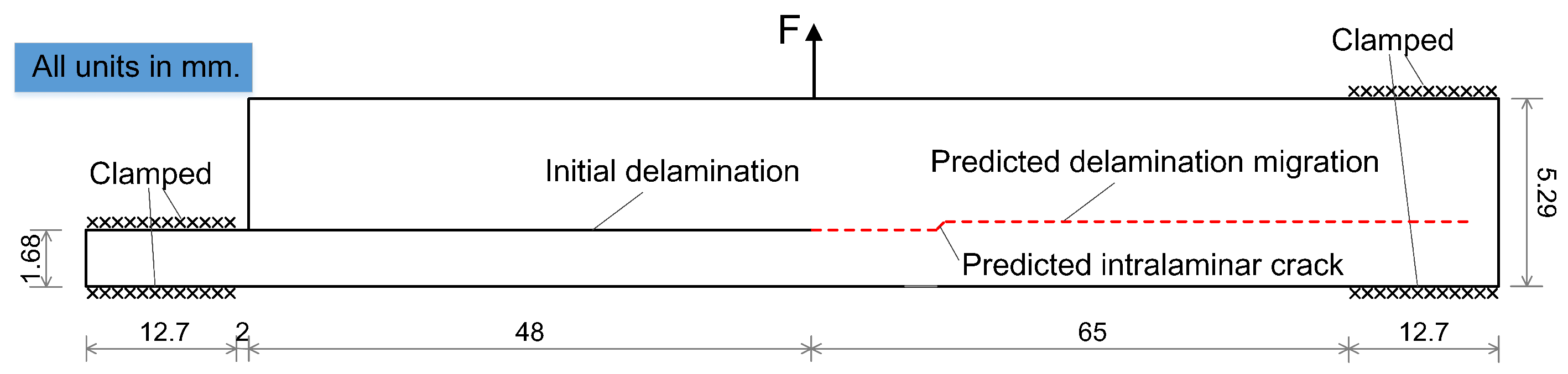
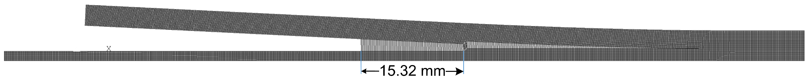
4.2. Delamination Migration

The delamination migration problem, in which delamination normally grows and migrates into different interfaces together with matrix cracks, is a good example to check the capability of the FE model to reflect the interaction between the matrix crack and delamination. Many studies on experimental methods and simulation techniques for the purpose of investigating a delamination migration have been done in recent years [35,37,60,61].
After McElroy and his colleagues performed a numerical simulation of delamination migration by using the Abaqus continuum damage model for intralaminar cracks and the cohesive zone for delamination [62], they concluded that the migration initiation and subsequent delamination could not be predicted by this method. This is because this numerical method did not capture the relationship of the interaction between intralaminar and interlaminar failure. The approach proposed in this work, which reflected the interaction between delamination and intralaminar cracks, is believed to be suitable for modeling the delamination migration behavior in FRP composites. Therefore, a typical delamination migration problem in a laminated composite specimen is investigated to validate the capability of the proposed model.
In this section, the results of numerical damage simulation of the delamination migration of carbon fiber-reinforced polymer (CFRP) composite are presented, and the numerical results and experimental data [61] are compared together to validate the FE model.
The loading, boundary conditions, and geometric dimensions of specimens for verifying the performance of our approach are illustrated in Figure 7, and the material elastic properties of CFRP composites are illustrated in Table 1.
A specimen has 44 plies, and its layup sequence is as follows: [ 0 4 / 90 12 / 0 10 / 90 4 / T / 0 / 90 / 0 2 / 90 6 / 0 2 / 90 / 0 ] . Script “ T ” means the initial crack made by inserting PTFE (polytetrafluoroethylene) at an interface between a zero-degree ply and a stack of four 90-degree plies, and the length of the initial crack is 48 mm. Both ends of the specimen are clamped, and the upper surface suffers the tensile force controlled by the vertical tensile displacement. As the load increases, the initial crack propagates at the interface between the 0° and 90° layers. The propagating interface crack is then kinked into the adjacent upper 90° layer and becomes an intralaminar matrix crack. After matrix cracking, the crack reaches the upper interface and changes into an interlaminar crack. The red dashed line in Figure 7 is the expected crack path, which is the experimentally-tested delamination migration. To simulate multiple delaminations at interfaces between the individual plies, four longitudinal cohesive layers are used. A refined mesh using an element length of 0.12 mm was used in the simulation of a specimen and contained a total of 45,568 solid elements and 1616 interface elements, which changed a little by the calculation results with further mesh refining.
The contour plots of the damage variable at various load levels are presented in Figure 8, and the sequence of the interlaminar delamination and intralaminar matrix failure can be seen from the evolution of the damage contour. The cohesive element failure initiates at 73.2% of the ultimate load and progresses in the initial crack direction of the specimen, as shown in Figure 8a. The solid elements are not damaged before the matrix damage initiates and the interface crack has migrated. The initial interface crack propagates for some time and then begins to penetrate into the adjacent upper 90° solid layer. The intralaminar damage (migration) occurs at solid elements, while delamination stops at a certain point (migration point) and does not propagate, as shown in Figure 8b. At this stage, the matrix crack propagates through the 90° layer from the bottom to the top, as shown in Figure 8c. As solid element damage reaches the other 0°/90° interface, interface element damage begins with the adjacent solid element damage. Then, the solid element and its adjacent interface element simultaneously fail. The degradation of the critical energy release rate at CZE helps the progression of delamination. The parameter β in Equation (11) is set to one, and so, the tension and shear failure are considered as the same weight at the interface elements in this simulation. The matrix crack is kinked, and delamination progresses at the top cohesive layer, while the load is dropping (Figure 8d). As such, delamination migration occurs from the original interface to the next top interface. The deformed shape of the model is shown in Figure 9, and from Figure 8 and Figure 9, it can be seen that the present approach can simulate the delamination migration in FRP laminates and has the capability to capture the interaction between the matrix crack and delamination.
The numerical result of delamination migration by using CDM and CZM together without coupling is shown in Figure 10. The initial delamination propagates and then penetrates into the adjacent solid layer. However, the top cohesive elements do not meet the fracture criterion, and the damage grows in the longitudinal direction of the matrix material.
This means that delamination due to the matrix crack (which is often seen in the failure of the composites) cannot be explained by the uncoupled model. While the process continues, the convergence condition of the calculation is not satisfied, and so, the result is divergent. This means that accurate simulation results cannot be obtained in failure problems of composite laminates, when the interactive behavior in the case of using two models together is not set.
The numerical result of the distance between the initial delamination tip point and the migration starting point is 15.32 mm (as shown in Figure 11) and matches well with the distance (15 mm) obtained from the experiments. The numerical force-displacement curve by the present model is compared with that of the experiments for the CFRP composites in Figure 12. It is apparent from the plots that the force-displacement response results in the simulation and experiment have good agreement.

5. Conclusions

A novel method for modeling the interaction of delamination and intralaminar cracks in FRP laminates is presented based on the coupling of both approaches of CDM and CZM in the paper. The initiation and evolution of intra- and inter-laminar damage of composites is modeled using the material property degradation method of continuum damage mechanics with two independent damage variables and the cohesive zone method with the mixed mode damage variable, respectively, and the interactions are considered based on the fracture energy dissipation. The developed numerical analysis model can effectively simulate the progressive damage failure and coupling effect of multiple failure mechanisms. The interactions between fiber failure, matrix failure, and delamination are investigated, and the insight for the simulation of the complex failure processes of composite laminates such as delamination migration is provided. The numerical results match well with those of the experiments, proving that the proposed approach has a high capability to predict the FRP composite damage failure and strength prediction.

Author Contributions

K.Y. and Z.W. conceived of and designed the paper; K.Y. performed the numerical simulations and wrote the paper; K.Y. and S.K. analyzed and evaluated the results; M.C., J.K., and J.L. assisted in the analysis of the results and C.R. corrected the language of the revised manuscript for submission.

Funding

This work is supported by the National Natural Science Foundation of China Grant Numbers 11272096, 11472086.

Conflicts of Interest

The authors declare no conflict of interest.

References

  1. Xin, S.H.; Wen, H.M. A progressive damage model for fiber reinforced plastic composites subjected to impact loading. Int. J. Impact Eng. 2015, 75, 40–52. [Google Scholar] [CrossRef]
  2. Yang, D.; Ye, J.; Tan, Y.; Sheng, Y. Modeling progressive delamination of laminated composites by discrete element method. Comp. Mat. Sci. 2011, 50, 858–864. [Google Scholar] [CrossRef]
  3. Ullah, H.; Harland, A.R.; Silberschmidt, V.V. Damage modeling in woven-fabric CFRP laminates under large-deflection bending. Comp. Mat. Sci. 2012, 64, 130–135. [Google Scholar] [CrossRef]
  4. Fang, X.J.; Zhou, Z.Q.; Cox, B.N.; Yang, Q.D. High-fidelity simulations of multiple fracture processes in a laminated composite in tension. J. Mech. Phys. Solids 2011, 59, 1355–1373. [Google Scholar] [CrossRef]
  5. Salavatian, M.; Smith, L.V. An investigation of matrix damage in composite laminates using continuum damage mechanics. Comput. Struct. 2015, 131, 565–573. [Google Scholar] [CrossRef]
  6. Zhong, S.; Guo, L.; Liu, G.; Lu, H.; Zeng, T. A continuum damage model for three-dimensional woven composites and finite element implementation. Comput. Struct. 2015, 128, 1–9. [Google Scholar] [CrossRef]
  7. Yun, K.; Wang, Z.; Ronald, S.; Pak, Y. An advanced continuum damage mechanics model for predicting the crack progress process based on the consideration of the influence of crack direction under quasi-static load. Int. J. Mech. Sci. 2017, 130, 487–496. [Google Scholar] [CrossRef]
  8. Schreter, M.; Neuner, M.; Hofstetter, G. Evaluation of the Implicit Gradient-Enhanced Regularization of a Damage-Plasticity Rock Model. Appl. Sci. 2018, 8, 1004. [Google Scholar] [CrossRef]
  9. Kachanov, L.M. On the time to failure under creep condition. In Akad Nauk USSR; Otd Techn Nauk; AN SSSR: Moscow, Russian, 1958; Volume 8, pp. 26–31. [Google Scholar]
  10. Maimí, P.; Camanho, P.P.; Mayugo, J.A.; Dávila, C.G. A continuum damage model for composite laminates: Part I—Constitutive model. Mech. Mater. 2007, 39, 897–908. [Google Scholar] [CrossRef]
  11. Maimí, P.; Camanho, P.P.; Mayugo, J.A.; Dávila, C.G. A continuum damage model for composite laminates: Part II—Computational implementation and validation. Mech. Mater. 2007, 39, 909–919. [Google Scholar] [CrossRef]
  12. Chen, J.F.; Morozov, E.V.; Shankar, K. A combined elastoplastic damage model for progressive failure analysis of composite materials and structures. Compos. Struct. 2012, 94, 3478–3489. [Google Scholar] [CrossRef]
  13. Nuismer, R.J.; Tan, S.C. The role of matrix cracking in the continuum constitutive behavior of a damaged composite ply. In Mechanics of Composite Materials: Recent Advances; Pergamon Press Offices: New York, NY, USA, 1983; pp. 437–448. [Google Scholar]
  14. Salavatian, M.; Smith, L. An improved analytical model for shear modulus of fiber reinforced laminates with damage. Compos. Sci. Technol. 2014, 105, 9–14. [Google Scholar] [CrossRef]
  15. Yun, K.; Wang, Z. A damage model based on the introduction of a crack direction parameter for FRP composites under quasi-static load. Compos. Struct. 2018, 184, 388–399. [Google Scholar] [CrossRef]
  16. Cicco, D.D.; Taheri, F. Delamination Buckling and Crack Propagation Simulations in Fiber-Metal Laminates Using xFEM and Cohesive Elements. Appl. Sci. 2018, 8, 2440. [Google Scholar] [CrossRef]
  17. Yang, B.; Wang, Z.; Zhou, L. Study on the low-velocity impact response and CAI behavior of foam-filled sandwich panels with hybrid facesheet. Compos. Struct. 2015, 132, 1129–1140. [Google Scholar] [CrossRef]
  18. Yang, B.; Wang, Z.; Zhou, L. Experimental and numerical investigation of interply hybrid composites based on woven fabrics and PCBT resin subjected to low-velocity impact. Compos. Struct. 2015, 132, 464–476. [Google Scholar] [CrossRef]
  19. Dimitri, R.; Zavarise, G. Isogeometric treatment of frictional contact and mixed mode debonding problems. Comput. Mech. 2017, 60, 315–332. [Google Scholar] [CrossRef]
  20. Dimitri, R.; Tornabene, F.; Zavarise, G. Analytical and numerical modeling of the mixed-mode delamination process for composite moment-loaded double cantilever beams. Compos. Struct. 2018, 187, 535–553. [Google Scholar] [CrossRef]
  21. Dugdale, D.S. Yielding of steel sheets containing slits. J. Mech. Phys. Solids 1960, 8, 100–104. [Google Scholar] [CrossRef]
  22. Barenblatt, G.I. The mathematical theory equilibrium cracks brittle fracture. Adv. Appl. Mech. 1962, 7, 55–129. [Google Scholar]
  23. Rose, J.H.; Ferrante, J.; Smith, J.R. Universal binding energy curves for metals and bimetallic interfaces. Phys. Rev. Lett. 1981, 47, 675–678. [Google Scholar] [CrossRef]
  24. Hillerborg, A.; Modéer, M.; Petersson, P.E. Analysis of crack formation and crack growth in concrete by means of fracture mechanics and finite elements. Cement. Concr. Res. 1976, 6, 773–781. [Google Scholar] [CrossRef]
  25. Ataş, A.; Soutis, C. Application of cohesive zone elements in damage analysis of composites: Strength prediction of a single-bolted joint in CFRP laminates. Int. J. Nonlinear Mech. 2014, 66, 96–104. [Google Scholar] [CrossRef]
  26. Harper, P.W.; Hallett, S.R. Cohesive zone length in numerical simulations of composite delamination. Eng. Fract. Mech. 2008, 75, 4774–4792. [Google Scholar] [CrossRef] [Green Version]
  27. Schellekens, J.C.J.; Borst, R.D. On the numerical integration of interface elements. Int. J. Numer. Meth. Eng. 2010, 36, 43–66. [Google Scholar] [CrossRef]
  28. Chandra, N.; Li, H.; Shet, C. Some issues in the application of cohesive zone models for metal-ceramic interfaces. Int. J. Solids Struct. 2002, 39, 2827–2855. [Google Scholar] [CrossRef]
  29. Volokh, K.Y. Comparison between cohesive zone models. Int. J. Numer. Meth. Eng. 2010, 20, 845–856. [Google Scholar] [CrossRef]
  30. Dogan, F.; Hadavinia, H.; Donchev, T. Delamination of impacted composite structures by cohesive zone interface elements and tiebreak contact. Cent. Eur. J. Eng. 2012, 2, 612–626. [Google Scholar] [CrossRef] [Green Version]
  31. Park, K.; Paulino, G.H. Cohesive zone models: A critical review of traction-separation relationships across fracture surfaces. Appl. Mech. Rev. 2011, 64, 1–20. [Google Scholar] [CrossRef]
  32. Dimitri, R.; Cornetti, P.; Mantic, V. Mode-I debonding of a double cantilever beam: A comparison between cohesive crack modeling and Finite Fracture Mechanics. Int. J. Solids Struct. 2017, 124, 57–72. [Google Scholar] [CrossRef]
  33. Maimí, P.; Camanho, P.P.; Mayugo, J.A. Matrix cracking and delamination in laminated composites. Part II: Evolution of crack density and delamination. Mech. Mater. 2011, 43, 194–211. [Google Scholar] [CrossRef]
  34. Rebière, J.L.; Gamby, D. A criterion for modeling initiation and propagation of matrix cracking and delamination in cross-ply laminates. Compos. Sci. Technol. 2004, 64, 2239–2250. [Google Scholar] [CrossRef]
  35. Hallett, S.R.; Jiang, W.G.; Khan, B.; Wisnom, M.R. Modeling the interaction between matrix cracks and delamination damage in scaled quasi-isotropic specimens. Compos. Sci. Technol. 2008, 68, 80–89. [Google Scholar] [CrossRef]
  36. Mcelroy, A.M.; Ratcliffe, J.G.; Czabaj, M.; Wang, J.; Yuan, F.G. A numerical and experimental study of damage growth in a composite laminate. In American Society for Composites Technical Conference; NF1676L-18068; NASA Langley Research Center: Hampton, VA, USA, 2014. [Google Scholar]
  37. Carvalho, N.V.D.; Chen, B.Y.; Pinho, S.T. Modeling delamination migration in cross-ply tape laminates. Compos. Part A-Appl. Sci. Manuf. 2015, 71, 192–203. [Google Scholar] [CrossRef]
  38. Ullah, H.; Harland, A.R.; Silberschmidt, V.V. Characterisation of mechanical behaviour and damage analysis of 2D woven composites under bending. Compos. Part B-Eng. 2015, 75, 156–166. [Google Scholar] [CrossRef] [Green Version]
  39. Meer, F.P.V.D.; Sluys, L.J. Mesh-independent modeling of both distributed and discrete matrix cracking in interaction with delamination in composites. Eng. Fract. Mech. 2010, 77, 719–735. [Google Scholar] [CrossRef]
  40. Zhao, L.; Zhi, J.; Zhang, J. XFEM simulation of delamination in composite laminates. Compos. Part A-Appl. Sci. Manuf. 2016, 80, 61–71. [Google Scholar] [CrossRef]
  41. Li, X.; Chen, J. An extended cohesive damage model for simulating multicrack propagation in fiber composites. Compos. Struct. 2016, 143, 1–8. [Google Scholar] [CrossRef]
  42. Li, X.; Chen, J. The implementation of the extended cohesive damage model for multicrack evolution in laminated composites. Compos. Struct. 2016, 139, 68–76. [Google Scholar] [CrossRef] [Green Version]
  43. Fries, T.; Baydoun, M. Crack propagation with the extended finite element method and a hybrid explicit–implicit crack description. Int. J. Numer. Meth. Eng. 2012, 89, 1527–1558. [Google Scholar] [CrossRef]
  44. Carollo, V.; Reinoso, J.; Paggi, M. A 3D finite strain model for intralayer and interlayer crack simulation coupling the phase field approach and cohesive zone model. Compos. Struct. 2017, 182, 636–651. [Google Scholar] [CrossRef]
  45. Wang, Y.; Waisman, H. Progressive delamination analysis of composite materials using XFEM and a discrete damage zone model. Comput. Mech. 2015, 55, 1–26. [Google Scholar] [CrossRef]
  46. Wang, Y.; Waisman, H. From diffuse damage to sharp cohesive cracks: A coupled XFEM framework for failure analysis of quasi-brittle materials. Comput. Methods Appl. Mech. Eng. 2016, 299, 57–89. [Google Scholar] [CrossRef]
  47. Moura, M.F.S.F.D.; Gonçalves, J.P.M. Modeling the interaction between matrix cracking and delamination in carbon–epoxy laminates under low velocity impact. Compos. Sci. Technol. 2004, 64, 1021–1027. [Google Scholar] [CrossRef]
  48. Wang, L.; Zheng, C.; Luo, H.; Wei, S.; Wei, Z. Continuum damage modeling and progressive failure analysis of carbon fiber/epoxy composite pressure vessel. Compos. Struct. 2015, 134, 475–482. [Google Scholar] [CrossRef]
  49. Maimí, P.; Mayugo, J.A.; Camanho, P.P. A Three-dimensional Damage Model for Transversely Isotropic Composite Laminates. J. Compos. Mater. 2008, 42, 2717–2745. [Google Scholar] [CrossRef]
  50. Alfano, G.; Crisfield, M.A. Finite element interface models for the delamination analysis of laminated composites: Mechanical and computational issues. Int. J. Numer. Meth. Eng. 2001, 50, 1701–1736. [Google Scholar] [CrossRef]
  51. Zhang, J.; Liu, F.; Zhao, L. A progressive damage analysis based characteristic length method for multi-bolt composite joints. Compos. Struct. 2014, 108, 915–923. [Google Scholar] [CrossRef]
  52. Hashin, Z. Fatigue failure criteria for unidirectional fiber composites. J. Appl. Mech. 1981, 48, 846–852. [Google Scholar] [CrossRef]
  53. Espinosa, H.D.; Zavattieri, P.D. A grain level model for the study of failure initiation and evolution in polycrystalline brittle materials. Part II: Numerical examples. Mech. Mater. 2003, 35, 365–394. [Google Scholar] [CrossRef]
  54. Dávila, C.G.; Rose, C.A.; Camanho, P.P. A procedure for superposing linear cohesive laws to represent multiple damage mechanisms in the fracture of composites. Int. J. Fract. 2009, 158, 211–223. [Google Scholar] [CrossRef]
  55. Reeder, J.R. An evaluation of mixed-Mode delamination failure criteria. In Technical Memorandum-1992-104210; NASA Langley Research Centre: Hampton, VA, USA, 1992. [Google Scholar]
  56. Yuan, Z.; Fish, J. Are the cohesive zone models necessary for delamination analysis. Comput. Methods Appl. Mech. Eng. 2016, 310, 567–604. [Google Scholar] [CrossRef]
  57. Green, B.G.; Wisnom, M.R.; Hallett, S.R. An experimental investigation into the tensile strength scaling of notched composites. Compos. Part A-Appl. Sci. Manuf. 2007, 38, 867–878. [Google Scholar] [CrossRef]
  58. Lammerant, L.; Verpoest, I. Modeling of the interaction between matrix cracks and delaminations during impact of composite plates. Compos. Sci. Technol. 1996, 56, 1171–1178. [Google Scholar] [CrossRef]
  59. Lapczyk, I.; Hurtado, J.A. Progressive damage modeling in fiber-reinforced materials. Compos. Part A-Appl. Sci. Manuf. 2007, 38, 2333–2341. [Google Scholar] [CrossRef]
  60. Ratcliffe, J.G.; Czabaj, M.W.; Obrien, T.K. Characterizing Delamination Migration in Carbon/Epoxy Tape Laminates; Ratcliffe, J.G., Ed.; DEStech Publications Inc.: Lancaster, PA, USA, 2012. [Google Scholar]
  61. Ratcliffe, J.G.; Decarvalho, N.V. Investigating Delamination Migration in Composite Tape Laminates. In Proceedings of the European Conference on Composite Materials, Seville, Spain, 22–26 June 2014. [Google Scholar]
  62. Mcelroy, M.; Leone, F.; Ratcliffe, J. Simulation of delamination-migration and core crushing in a CFRP sandwich structure. Compos. Part A-Appl. Sci. Manuf. 2015, 79, 192–202. [Google Scholar] [CrossRef]
Figure 1. Three coordinate systems for considering matrix cracking.
Applsci 09 00314 g001
Figure 2. Bilinear mixed mode traction-separation law.
Applsci 09 00314 g002
Figure 3. Configuration of a unidirectional specimen with a central cut.
Applsci 09 00314 g003
Figure 4. Finite element mesh.
Applsci 09 00314 g004
Figure 5. Deformed shape of the unidirectional specimen.
Applsci 09 00314 g005
Figure 6. The predicted remote stress-displacement curve.
Applsci 09 00314 g006
Figure 7. Test setup in delamination migration.
Applsci 09 00314 g007
Figure 8. Contour plots of the damage variable at various load levels: (a) at the initial delamination propagation; (b) at the moment of starting migration; (c) at the matrix cracking; (d) at the load dropping after migration.
Applsci 09 00314 g008
Figure 9. Deformed shape in delamination migration.
Applsci 09 00314 g009
Figure 10. Contour plot of the damage variable by the model without any interactive module.
Applsci 09 00314 g010
Figure 11. The position of delamination migration.
Applsci 09 00314 g011
Figure 12. Comparison of the simulated and experimental force-displacement curves.
Applsci 09 00314 g012
Table 1. Elastic properties of the CFRP composite.
E 11 (GPa) E 22 = E 33 (GPa) G 12 = G 13 (GPa) G 23 (GPa) ν 12 = ν 13 ν 23
16111.385.173.980.320.436

