Article

Surface Topography-Based Positioning Accuracy of Maxillary Templates Fabricated by the CAD/CAM Technique for Orthognathic Surgery without an Intermediate Splint

1
Department of Oral and Maxillofacial Surgery, School of Dentistry, Dental Science Research Institute, Chonnam National University, Gwangju 61186, Korea
2
Hwang Soon Jung’s Dental Clinic for Oral and Maxillofacial Surgery, Woonam Building, 2,3 F, 349, Gangnam-daero, Seocho-gu, Seoul 06626, Korea
*
Author to whom correspondence should be addressed.
Appl. Sci. 2019, 9(22), 4928; https://doi.org/10.3390/app9224928
Submission received: 10 October 2019 / Revised: 1 November 2019 / Accepted: 13 November 2019 / Published: 16 November 2019
(This article belongs to the Special Issue Dynamic Models of Biology and Medicine, Volume II)

Abstract

:
Computer-aided design/computer-aided manufacturing (CAD/CAM)-based maxillary templates can transfer a surgical plan accurately only when the template is positioned correctly. Our study aimed to evaluate the positioning accuracy of the CAD/CAM-based template for maxillary orthognathic surgery using dry skulls. After reconstruction of a three-dimensional (3D) virtual skull model, a surface-based surgical template for Le Fort I osteotomy was designed and fabricated using CAD/CAM and 3D printing technology. To determine accuracy, the deviation of the template between the planned and the actual position and the fitness of the template were evaluated. The mean deviation was 0.41 ± 0.30 mm in the medio-lateral direction, 0.55 ± 0.59 mm in the antero-posterior direction, and 0.69 ± 0.59 mm in the supero-inferior direction. The root mean square deviation between the planned and the actual position of the template was 1.21 ± 0.54 mm. With respect to the fitness of the template, the mean distance between the inner surface of the template and the underlying bone surface was 0.76 ± 0.24 mm. CAD/CAM-based templates showed precise positioning and good fitness. These results suggest that surface topography-based CAD-CAM templates can be considered as an alternative solution in replacing the traditional intermediate splints for the transfer of surgical plans.

1. Introduction

Correct repositioning of the maxilla to the planned position is essential to achieve a successful treatment outcome in orthognathic surgery [1,2,3]. To transfer a surgical plan to the operation field, most surgeons use intermediate splints which require several error-prone procedures including making a cast model, transfer of the face bow, model surgery, and fabrication of acrylic splints [4,5]. In addition, intermediate splints can provide the transverse and sagittal position of the maxilla; however, the vertical position of the maxilla in relation to the basal skull is controlled intraoperatively by the surgeon on the basis of the various intraoral and/or extraoral measurements, including the distance between the reference points and the amount of incisal exposure [6,7,8,9]. In the comparison of model surgery prediction with the actual surgical changes, over- or under-advancement of the maxilla occurred in over 50% of patients, and over- or under-impaction also occurred in over 40% of patients [10]. In another study, the difference between the model surgery and the surgical result ranged from −7.7 to 6.6 mm, and the absolute mean difference was 2.2 mm [11]. Recently, Mulier et al. [12] reported that a repositioning error of the maxilla between 2 and 4 mm was seen in 16.4% and 20.0% for anterior posterior and superior inferior directions, respectively.
Recent advances in computer-aided design computer-aided manufacturing (CAD/CAM) technology and three-dimensional (3D) printing techniques have constituted a paradigm shift in orthognathic surgery, which has enabled more accurate treatment planning and surgery [1,9,13,14,15]. Two-dimensional cephalometric analysis has been replaced by 3D computed tomography (CT) analysis, and postoperative surgical outcome has been predicted using 3D simulation programs in place of paper surgery [16,17]. Various CAD/CAM-based templates for orthognathic surgery have been developed as an alternative to intermediate splints [1,3,6,9,18,19,20,21]. These templates include surgical templates and patient-specific implants (PSI). Surgical templates can provide the location and orientation of the osteotomy line, the areas of bone interferences, and the final position of the bony segments [1,2,9,20,21]. Following repositioning of the bony segments using the template, the mini-plate is bent intraoperatively according to the contours of the bone, which is then applied for fixation. In contrast, PSI can serve not only as a positioning or osteotomy guide but can also be used in osteosynthesis for rigid fixation of the maxillary segment [3,18,19,20]. Currently, such 3D CAD/CAM-based templates have been widely used for various facial skeleton surgeries including Le Fort I osteotomy, bilateral sagittal split ramus osteotomy, genioplasty, or facial contouring surgery [15,22,23,24,25,26].
With the increased use of CAD/CAM-based templates, several investigators assessed the surgical accuracy after orthognathic surgery using CAD/CAM-based templates [3,18,20,27]. Although successful surgical outcomes have been reported in most of patients, clinically significant surgical error occurred in some patients. Furthermore, the cases where the CAD/CAM-based template was not usable were also reported. Hence, in addition to the use of CAD/CAM-based templates in orthognathic surgery, several surgeons have also prepared an intermediate splint as an alternative plan [3,18]. Therefore, to ultimately replace the intermediate splint, researches on the causes of the surgical error or the situations when the template is not usable are necessary. In the previous reports, the positioning accuracy of the template has been suggested as one of the contributing factors to the surgical accuracy [28,29]. CAD/CAM-based templates can transfer the presurgical plan to the surgical site accurately only when the template is positioned correctly. Nevertheless, to our knowledge, few reports have assessed the positioning accuracy of the template. Thus, our study aimed to evaluate the accuracy of the positioning of the CAD/CAM-based templates in orthognathic surgery using dry skulls.

2. Materials and Methods

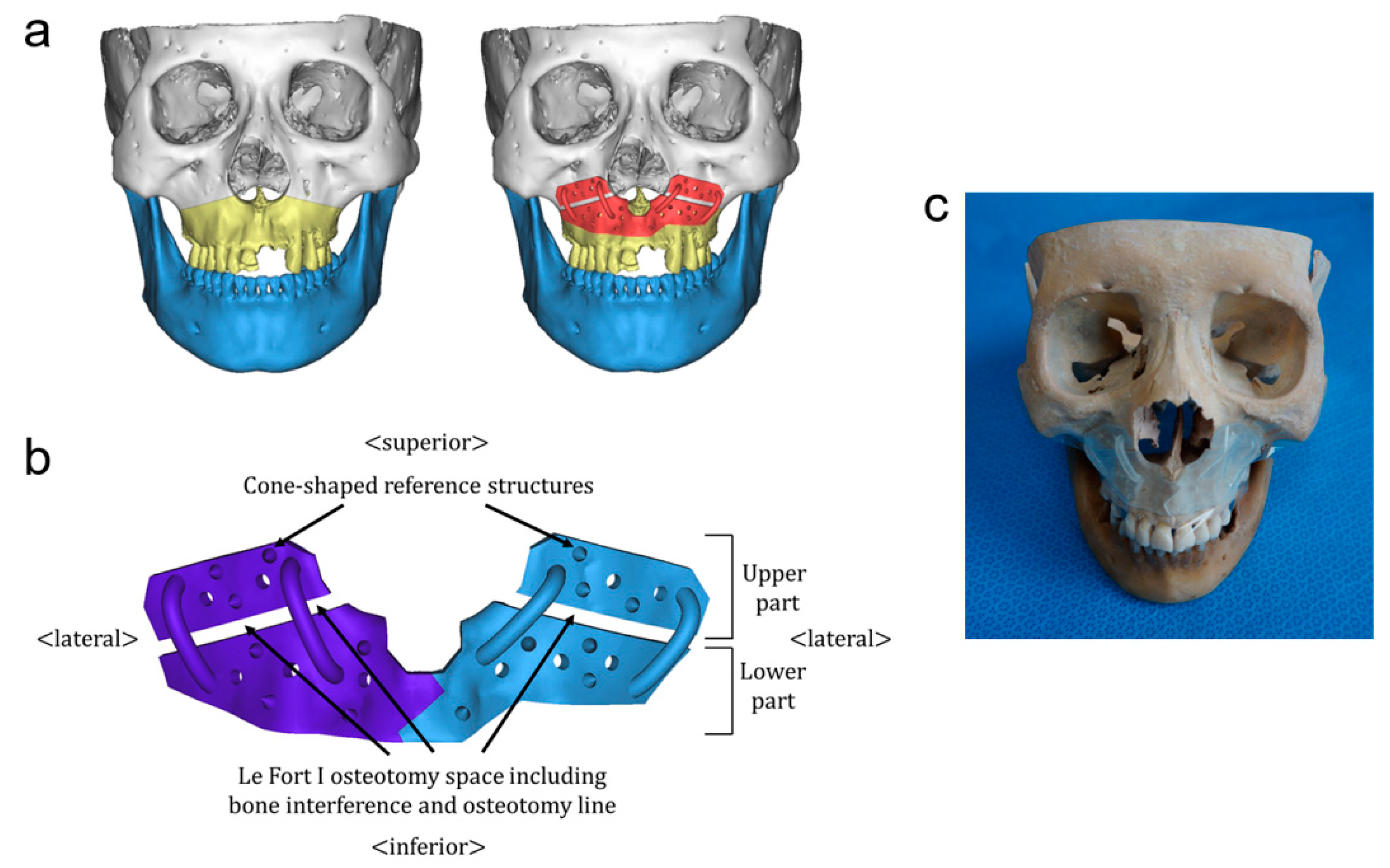
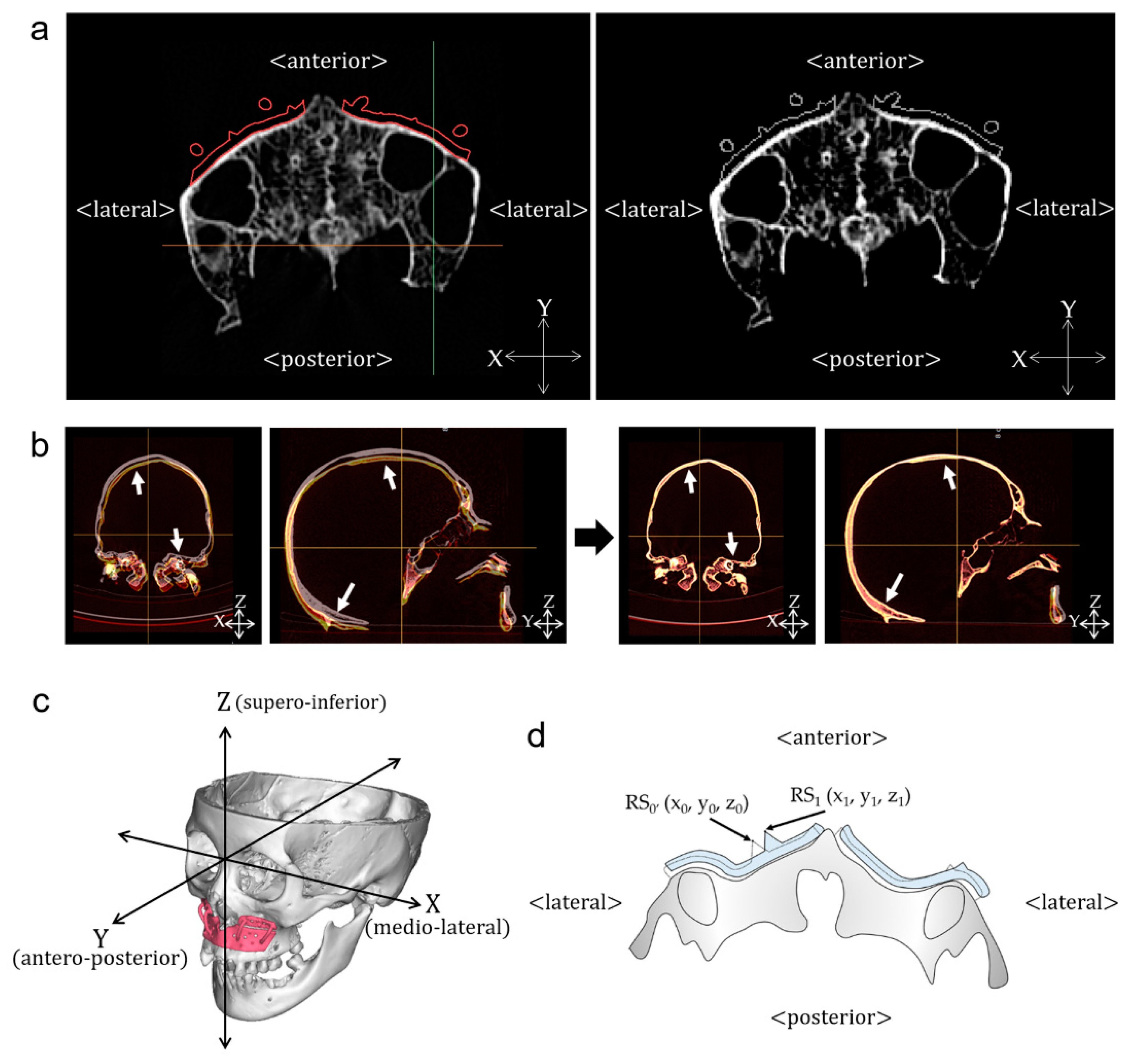
2.1. Design of CAD/CAM-Based Surgical Templates

Ten dry skulls with an intact maxillary anterior surface were included in our study. 3D computed tomography (CT) scans (SOMATOM Sensation 10; Siemens, Germany) were obtained under 120 kVp and 80 mA with a slice thickness of 0.75 mm. CT data (T0) were saved in the Digital Imaging and Communications in Medicine (DICOM) format and imported into Mimics software (Materialise, Leuven, Belgium). To construct a 3D virtual skull model, the threshold of the CT value was set between 250 and 3000 Hounsfield units. After construction of the virtual skull model, Le Fort I osteotomy was performed on the virtual skull models along the conventional Le Fort I osteotomy line that was set as the line from the most inferior point in the curvature of zygomaticomaxillary buttress to the midpoint of the piriform aperture area. Then, surgical templates for Le Fort I osteotomy were designed and fabricated using 3D printing technology [1] (Figure 1a). The design of the templates is described in detail below (Figure 1b)—surgical templates included two distinct parts (right and left parts) separated at the midline. For exact positioning of the template in the planned position, the template was designed to cover the zygomaticomaxillary buttress, piriform aperture, and maxillary anterior wall including the canine eminence, which can provide “3D lock” [3,30]. The upper boundary of the template was set at 8 mm above the Le Fort I osteotomy line and the lower boundary was set at 14 mm below the Le Fort I osteotomy line. The right and left parts of the template covered the anterior nasal spine and were joined at the maxillary midline with a wedge-form interlocking structure for precise adaptation. Between the upper and lower parts, Le Fort I osteotomy space was generated to provide information about the osteotomy line and bone interference. To evaluate the deviation of the surgical template, we added 14 conical reference structures with a bottom diameter of 2.0 mm and a height of 2.0 mm (seven reference structures on each of the right and left parts) onto the template. For all surgical templates, the thickness was set to 2.0 mm. The designed surgical template was fabricated using a 3D printer. The CAD/CAM-based surgical templates were fitted on the maxilla by an oral and maxillofacial surgeon, and fixed with adhesive tape (Figure 1c). Subsequently, CT scan data (T1) were obtained to compare the actual position of the template with the planned position.

2.2. Deviation of the CAD/CAM-Based Surgical Templates

First, we combined the surgical template with the CT data at T0 and exported it to DICOM format (T0′) (Figure 2a). Using the 3D analysis program (OnDemand3D, Cybermed, Seoul, Korea), CT data at T0′ and T1 were imported and superimposed on the basis of the best fit of the cranial base structures (Figure 2b) [31]. To measure the deviation of the template, we established a 3D coordinate system (X, Y, Z) (X, medio-lateral; Y, antero-posterior; Z, supero-inferior) (Figure 2c). The Frankfort horizontal plane (FH plane), which passed through both the orbitale and the right porion, was used as a horizontal reference plane, and the x-axis was set as the vector from the right to the left orbitale. The midsagittal plane was defined as the plane that is perpendicular to the x-axis and passed through a nasion. The coronal plane was defined as the plane that passed through the line passing both orbitales and that was perpendicular to the FH plane [31,32]. To quantify the accuracy of the positioning of the template, we assessed the changes of the 3D coordinates of each conical reference structure from T0′ to T1 (Figure 2d) and calculated the root mean square deviation (RMSD) between T0′ and T1.
RMSD = 1 n i = 1 n ( R S 0 , i R S 1 , i ) 2
For all the data points, R S 0 , i was the planned position of reference structure, and R S 1 , i was the actual position of reference structure. Also, n refers to the total number of reference structure in each analysis.
To determine the effect of the contact area between the template and the underlying bone on the positioning accuracy, we obtained the area of inner surface of the template and performed the correlation analysis.

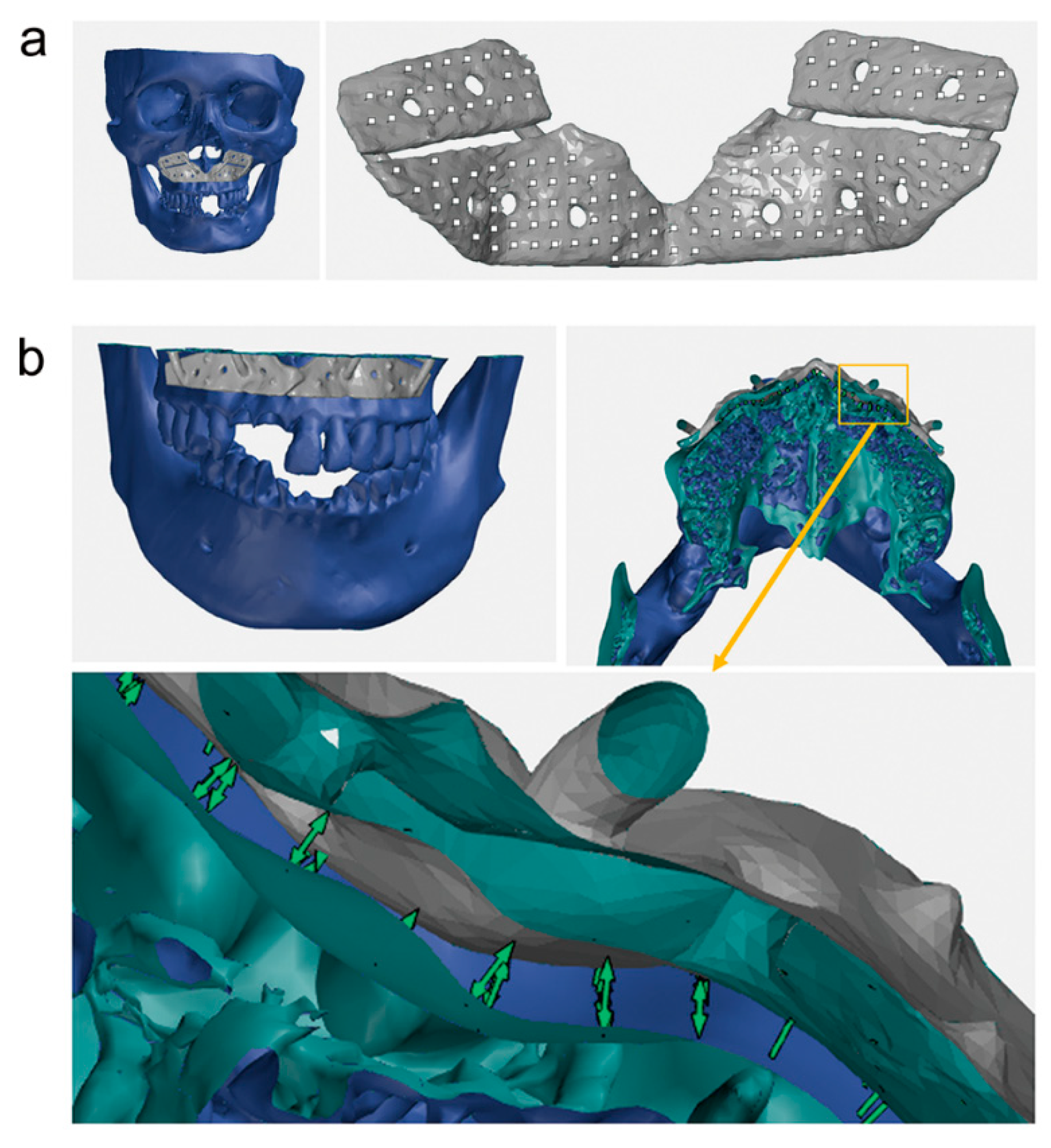
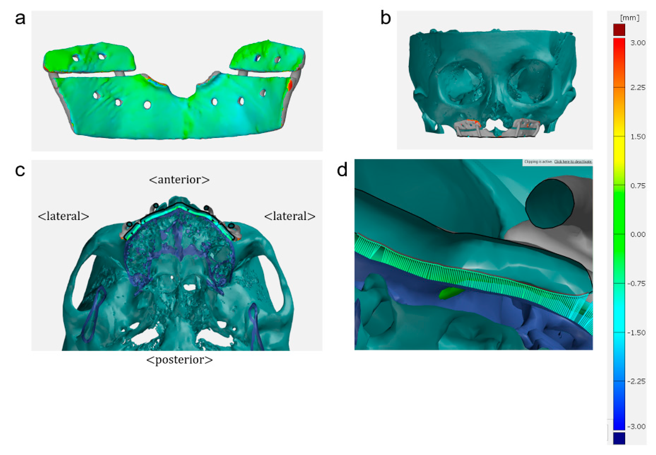
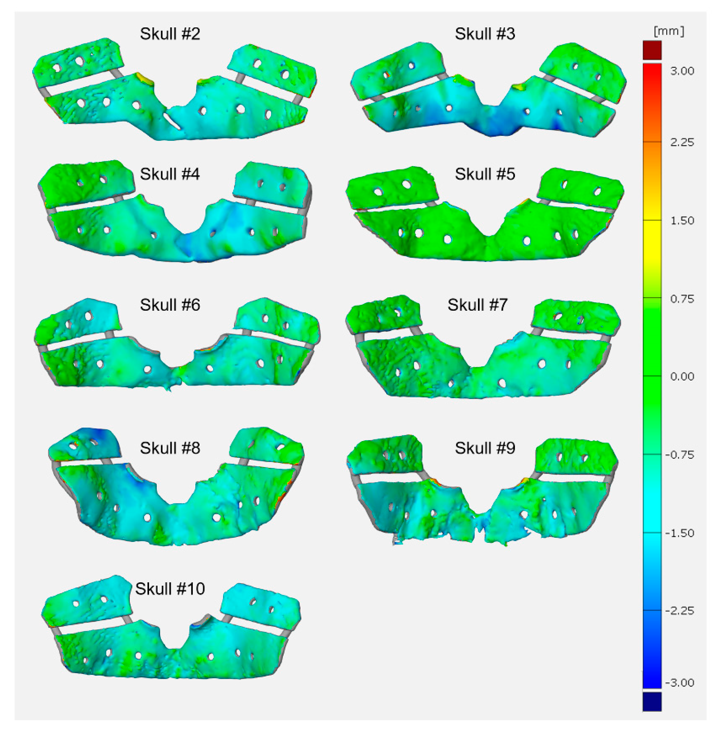
2.3. Fitness of the CAD/CAM-Based Surgical Templates

To evaluate the fitness of the template, we measured the distance between the inner surface of the template and the underlying bone surface. First, CT data taken at T1 were imported into Mimics software (Materialise, Leuven, Belgium), and surgical templates and skull models were constructed separately and saved in stereolithography format (STL) (Figure 3a). STL files of the templates and skull models were imported to the inspection program (GOM Inspect; GOM mbH, Braunschiweig, Germany). On the inner surface of the template, evenly distributed surface points were created automatically by the software, where the distance between each point was set to 2.0 mm [33]. After those points were projected to the underlying bone surface, the distance between the point on the inner surface of the template and its projected point on the underlying bone surface was calculated (Figure 3b). To show the fitness of the template better, a color difference map that can illustrate fitness of the template at any single point of the inner surface of the template was used (Figure 4).

2.4. Statistical Analysis

Statistical analysis was performed using the SPSS version 23.0 (SPSS Inc., Chicago, IL, USA). The data were tested for normal distribution through a Kolmogorov–Smirnov test. To evaluate the positioning accuracy of the surgical template, a paired t-test was performed for x-, y- and z-coordinates between the planned and the actual positions. Spearman’s correlation coefficient was used to investigate the correlation between the contact area of the template and the positioning accuracy. The level of significance was set at p < 0.05.

3. Results

3.1. Deviation of the CAD/CAM-Based Surgical Templates

The absolute deviation of the template position between virtual surgery (planned position) and actual surgery (actual position) are shown in Table 1. For 140 evaluated reference structures of 10 experiments, the mean absolute deviation was 0.41 ± 0.30 mm in the medial-lateral direction, 0.55 ± 0.59 mm in the anterior-posterior direction, and 0.69 ± 0.59 mm in the superior-inferior direction. There were statistically significant differences between the planned and the actual positions of the template in all directions (p < 0.001). The mean absolute deviation of the template ranged from 0.26 to 0.53 mm for medio-lateral direction, from 0.23 to 1.22 mm for antero-posterior direction, and 0.21 to 1.57 mm for supero-inferior direction. The mean RMSD between the planned and the actual positions of the template was 1.21 ± 0.54 mm, and the maximum and minimum RMSDs were 2.18 and 0.65 mm, respectively (Table 2). A color difference map shows clinically acceptable fitness of the template at any single point of the inner surface of the template for each experiment in Figure 4 and Figure 5.
In this study, the contact area between the template and underlying bone was 1332.63 ± 187.56 mm2, and ranged from 1129.16 to 1765.33 mm2. There was no statistically significant correlation between the contact area of the template and the positioning accuracy (RMSD) of the template (p = 0.793).

3.2. Fitness of the CAD/CAM-Based Surgical Templates

An average number of surface points created on the inner surface of the template for each experiment was 184.80 ± 35.32 (Table 3). For all 1848 created surface points in 10 dry skulls, the mean distance between the inner surface of the template and the underlying bone was 0.76 ± 0.24 mm (range of 0 to 2.38 mm). The mean distance between the inner surface of the template and the underlying bone for each skull ranged from 0.17 to 1.01 mm.

4. Discussion

Various CAD/CAM templates based on 3D surgical simulation have been developed to overcome limitations in the use of the intermediate splints in orthognathic surgery [1,3,6,18,19,20,21,30,34]. The CAD/CAM templates are designed on 3D virtual skull models generated from CT data, and are fabricated using 3D printing technology, or they are milled from titanium alloy blocks. During surgery, repositioning of the bony segment to the planned position can be accomplished accurately only when the template is located in the exact position deduced from the surgical simulation. When the template is not fixed in the planned position, subsequent procedures including osteotomy, removal of bone interference, and repositioning of the bony segments may be different from those obtained by the surgical simulation. In addition, the final surgical outcome can also be different when compared to the planned and predicted outcome.
Depending on the method used for fitting the template, the templates can be divided into two systems: (1) dentition-based system and (2) surface-based system. The dentition-based system includes the occlusal splint, which can provide a more accurate reproduction of the template position during surgery [2,9,21]. However, this system requires scanning of the dental cast and registration of the scanning data into CT data, which can be time-consuming and error-prone. Furthermore, undesirable preoperative tooth movement after impression and scanning of dentition may lead to generation of inaccurate templates. In the surface-based system, reproduction of the template position can be achieved by maxillary surface configuration without an occlusal splint. Thus, scanning of dental cast and data registration are not necessary [1,3,18,19,20,30]. Although the bulky template can result in distortion of perioral soft tissue, which makes it difficult to evaluate soft-tissue changes during the surgery, this system requires a template that covers its underlying bone surface as widely as possible and includes characterized anatomical structures.
Several previous studies reported successful surgical results after orthognathic surgery with surface-based CAD/CAM templates [3,18,19,30]. Bai et al. [30] proposed a technique using a pair of surface templates that records the 3D surface geometry of the region of interest as an alternative to the intermediate surgical wafer and reported that the templates fitted intimately with the outer surface of the maxilla. Gander et al. [19] used laser-sintered PSI as a positioning guide with concurrent rigid fixation after Le Fort I osteotomy and reported minimal inconsistency between the planning and postoperative results in quality analysis. Brunso et al. [18] used bone-supported guides for placement of the custom-machined titanium miniplates fabricated using CAD/CAM technology in six patients. They reported that the plates fitted perfectly with the anterior buttress of the maxilla and the surface of the mandibular body during the surgery. In their study, the average surface deviation between the presurgical plan and the final surgical results was 1.09 ± 0.78 mm (71.2% of values within 1.0 mm) for maxillary surgery and 0.61 ± 0.69 mm (75.3% of values within 1.0 mm) for mandibular surgery. In a case series of 32 maxillary osteotomy patients reported by Suojanen et al. [3], fitting of the custom-made osteosynthesis plate was excellent in 23 patients (71.9%), good in 4 patients (12.5%), acceptable in 4 patients (12.5%), and not usable in 1 patient (3.1%). In contrast to encouraging results of CAD/CAM-based template, clinically significant surgical errors (>2.0 mm) have also been reported. In the study by Mazzoni et al. [20], the accuracy showed a reproducibility of <2 mm in 7 out of 10 patients. However, three other cases exhibited maximum errors of 2.4, 3.2, and 6.0 mm. Heufelder et al. [27] also reported the maximum error of 2.02 mm after bimaxillary surgery using CAD/CAM-generated cutting guides and patient-specific implants. Regarding the cause of the surgical error in the template-based surgery, Lin et al. [29] suggested that the surgical error was attributed the contact surface between the template and the underlying bone, and that a wider or longer surgical template ensures a higher positioning accuracy.
In our study, we assessed the positioning accuracy of surface-based CAD/CAM templates, where the placement of the templates in the same position as the surgical simulation is essential to perform subsequent surgical procedures precisely. To maximize the positioning accuracy, the CAD/CAM template used in this study was designed to cover the zygomaticomaxillary buttress and piriform aperture. Furthermore, the right and left parts of the template were joined at the midline with wedge-form interlocking structures. Though there were statistically significant differences between the planned and actual positions of the template, mean absolute deviations (0.41 mm in medio-lateral direction, 0.55 mm in antero-posterior direction, and 0.69 mm in antero-posterior direction) and RMSD (1.07 mm) were clinically acceptable. The template exhibited more accurate positioning in the medio-lateral direction, followed by the antero-posterior and the supero-inferior directions. With respect to the fitness of the template, the gap between the inner surface of the surgical template and the underlying bone was also clinically acceptable (0.75 mm on average). These results suggest that surface-based CAD/CAM templates may be repositioned precisely without the help of occlusal splints.
There might be other consideration factors for the maxillary templates. First, it is necessary to consider the accuracy of the 3D printed template compared to the design of the template, and the possibility of deformation from 3D printing to actual use in surgery. In addition, when the template is fixed to the bone surface with screws, it is necessary to consider the technical aspects, as the excessive pressing force may reduce the intimate contact of other parts and increase the error occurrence. Another important consideration is the anatomical features of the site where the template will be located. When fastening the template to the thin maxilla, loosening of the screw may occur, and thus the movement of template may cause surgical errors. Insufficient maxillary bone height can reduce accuracy by reducing the area of bone covered by the template. When the template is designed to cover a large area of the maxilla in order to increase the suitability of the template, it is difficult to place the template due to large volume of the template.
In this study, we assessed the positioning accuracy of the CAD/CAM-based template. In addition to the positioning error of the surgical template, deformation of the template during surgery can also cause the surgical error [19,20,35]. Although the template was fixed passively on the dry skull using adhesive tape to avoid deformation in our study, we did not evaluate the deformation of the template after fixation on the bone. Thus, in future studies, it is necessary to evaluate conformational changes of the template.

5. Conclusions

In CAD/CAM-based surgical templates, including guide templates and PSIs, positioning of the template in the planned position is important to achieve the predicted surgical outcome successfully. In our study, surface-based CAD/CAM surgical templates showed precise positioning and good fitness. These results suggest that various surface-based CAD-CAM templates can be positioned on the basis of prior simulation without the help of occlusal splints and can serve as an alternative solution to the use of traditional intermediate splints for the transfer of surgical plans to the actual operation field.

Author Contributions

Conceptualization, S.J.H.; formal analysis, J.J.H.; funding acquisition, S.J.H.; investigation, J.J.H.; methodology, J.J.H.; supervision, S.J.H.; writing—original draft, J.J.H.; writing—review and editing, S.J.H.

Funding

This research received no external funding.

Acknowledgments

This study was supported by a grant (HI13C1491) from the Korea Health Technology R&D Project, Ministry of Health and Welfare, Republic of Korea.

Conflicts of Interest

The authors have no financial interest to declare in relation to the content of this article.

References

  1. Han, J.J.; Yang, H.J.; Hwang, S.J. Repositioning of the Maxillomandibular Complex Using Maxillary Template Adjusted Only by Maxillary Surface Configuration Without an Intermediate Splint in Orthognathic Surgery. J. Craniofacial Surg. 2016, 27, 1550–1553. [Google Scholar] [CrossRef] [PubMed]
  2. Li, B.; Zhang, L.; Sun, H.; Yuan, J.; Shen, S.G.; Wang, X. A novel method of computer aided orthognathic surgery using individual CAD/CAM templates: A combination of osteotomy and repositioning guides. Br. J. Oral Maxillofac. Surg. 2013, 51, e239–e244. [Google Scholar] [CrossRef] [PubMed]
  3. Suojanen, J.; Leikola, J.; Stoor, P. The use of patient-specific implants in orthognathic surgery: A series of 32 maxillary osteotomy patients. J. Cranio Maxillofac. Surg. 2016, 44, 1913–1916. [Google Scholar] [CrossRef] [PubMed]
  4. Ellis, E., 3rd. Accuracy of model surgery: Evaluation of an old technique and introduction of a new one. J. Oral Maxillofac. Surg. 1990, 48, 1161–1167. [Google Scholar] [CrossRef]
  5. Olszewski, R.; Reychler, H. Limitations of orthognathic model surgery: Theoretical and practical implications. Rev. Stomatol. Chir. Maxillofac. 2004, 105, 165–169. [Google Scholar] [CrossRef]
  6. Bai, S.; Shang, H.; Liu, Y.; Zhao, J.; Zhao, Y. Computer-aided design and computer-aided manufacturing locating guides accompanied with prebent titanium plates in orthognathic surgery. J. Oral Maxillofac. Surg. 2012, 70, 2419–2426. [Google Scholar] [CrossRef]
  7. Ferguson, J.W.; Luyk, N.H. Control of vertical dimension during maxillary orthognathic surgery. A clinical trial comparing internal and external fixed reference points. J. Cranio Maxillofac. Surg. 1992, 20, 333–336. [Google Scholar] [CrossRef]
  8. Kahnberg, K.E.; Sunzel, B.; Astrand, P. Planning and control of vertical dimension in Le Fort I osteotomies. J. Cranio Maxillofac. Surg. 1990, 18, 267–270. [Google Scholar] [CrossRef]
  9. Zinser, M.J.; Sailer, H.F.; Ritter, L.; Braumann, B.; Maegele, M.; Zoller, J.E. A paradigm shift in orthognathic surgery? A comparison of navigation, computer-aided designed/computer-aided manufactured splints, and “classic” intermaxillary splints to surgical transfer of virtual orthognathic planning. J. Oral Maxillofac. Surg. 2013, 71, 2151.e1–2151.e21. [Google Scholar] [CrossRef]
  10. Sharifi, A.; Jones, R.; Ayoub, A.; Moos, K.; Walker, F.; Khambay, B.; McHugh, S. How accurate is model planning for orthognathic surgery? Int. J. Oral Maxillofac. Surg. 2008, 37, 1089–1093. [Google Scholar] [CrossRef]
  11. Kwon, T.G.; Mori, Y.; Minami, K.; Lee, S.H. Reproducibility of maxillary positioning in Le Fort I osteotomy: A 3-dimensional evaluation. J. Oral Maxillofac. Surg. 2002, 60, 287–293. [Google Scholar] [CrossRef] [PubMed]
  12. Mulier, D.; Shaheen, E.; Shujaat, S.; Fieuws, S.; Jacobs, R.; Politis, C. How accurate is digital-assisted Le Fort I maxillary osteotomy? A three-dimensional perspective. Int. J. Oral Maxillofac. Surg. 2019. [Google Scholar] [CrossRef] [PubMed]
  13. Aboul-Hosn Centenero, S.; Hernandez-Alfaro, F. 3D planning in orthognathic surgery: CAD/CAM surgical splints and prediction of the soft and hard tissues results—Our experience in 16 cases. J. Cranio Maxillofac. Surg. 2012, 40, 162–168. [Google Scholar] [CrossRef] [PubMed]
  14. Chen, X.; Li, X.; Xu, L.; Sun, Y.; Politis, C.; Egger, J. Development of a computer-aided design software for dental splint in orthognathic surgery. Sci. Rep. 2016, 6, 38867. [Google Scholar] [CrossRef]
  15. Li, B.; Wei, H.; Zeng, F.; Li, J.; Xia, J.J.; Wang, X. Application of A Novel Three-dimensional Printing Genioplasty Template System and Its Clinical Validation: A Control Study. Sci. Rep. 2017, 7, 5431. [Google Scholar] [CrossRef]
  16. Kwon, T.G. Accuracy and reliability of three-dimensional computer-assisted planning for orthognathic surgery. Maxillofac. Plast. Reconstr. Surg. 2018, 40, 14. [Google Scholar] [CrossRef]
  17. Tominaga, K.; Habu, M.; Tsurushima, H.; Takahashi, O.; Yoshioka, I. CAD/CAM splint based on soft tissue 3D simulation for treatment of facial asymmetry. Maxillofac. Plast. Reconstr. Surg. 2016, 38, 4. [Google Scholar] [CrossRef]
  18. Brunso, J.; Franco, M.; Constantinescu, T.; Barbier, L.; Santamaria, J.A.; Alvarez, J. Custom-Machined Miniplates and Bone-Supported Guides for Orthognathic Surgery: A New Surgical Procedure. J. Oral Maxillofac. Surg. 2016, 74, 1061.e1–1061.e12. [Google Scholar] [CrossRef]
  19. Gander, T.; Bredell, M.; Eliades, T.; Rucker, M.; Essig, H. Splintless orthognathic surgery: A novel technique using patient-specific implants (PSI). J. Cranio Maxillofac. Surg. 2015, 43, 319–322. [Google Scholar] [CrossRef]
  20. Mazzoni, S.; Bianchi, A.; Schiariti, G.; Badiali, G.; Marchetti, C. Computer-aided design and computer-aided manufacturing cutting guides and customized titanium plates are useful in upper maxilla waferless repositioning. J. Oral Maxillofac. Surg. 2015, 73, 701–707. [Google Scholar] [CrossRef]
  21. Polley, J.W.; Figueroa, A.A. Orthognathic positioning system: Intraoperative system to transfer virtual surgical plan to operating field during orthognathic surgery. J. Oral Maxillofac. Surg. 2013, 71, 911–920. [Google Scholar] [CrossRef] [PubMed]
  22. Lim, S.H.; Kim, M.K.; Kang, S.H. Genioplasty using a simple CAD/CAM (computer-aided design and computer-aided manufacturing) surgical guide. Maxillofac. Plast. Reconstr. Surg. 2015, 37, 44. [Google Scholar] [CrossRef] [PubMed]
  23. Salvato, G.; Chiavenna, C.; Meazzini, M.C. Guide surgery osteotomy system (GSOS) a new device for treatment in orthognathic surgery. J. Cranio Maxillofac. Surg. 2014, 42, 234–238. [Google Scholar] [CrossRef] [PubMed]
  24. Suojanen, J.; Leikola, J.; Stoor, P. The use of patient-specific implants in orthognathic surgery: A series of 30 mandible sagittal split osteotomy patients. J. Cranio Maxillofac. Surg. 2017, 45, 990–994. [Google Scholar] [CrossRef] [PubMed]
  25. Yamauchi, K.; Yamaguchi, Y.; Katoh, H.; Takahashi, T. Tooth-bone CAD/CAM surgical guide for genioplasty. Br. J. Oral Maxillofac. Surg. 2016, 54, 1134–1135. [Google Scholar] [CrossRef]
  26. Yun, P.Y. The application of three-dimensional printing techniques in the fi eld of oral and maxillofacial surgery. J. Korean Assoc. Oral Maxillofac. Surg. 2015, 41, 169–170. [Google Scholar] [CrossRef]
  27. Heufelder, M.; Wilde, F.; Pietzka, S.; Mascha, F.; Winter, K.; Schramm, A.; Rana, M. Clinical accuracy of waferless maxillary positioning using customized surgical guides and patient specific osteosynthesis in bimaxillary orthognathic surgery. J. Cranio Maxillofac. Surg. 2017, 45, 1578–1585. [Google Scholar] [CrossRef]
  28. Chang, H.W.; Lin, H.H.; Chortrakarnkij, P.; Kim, S.G.; Lo, L.J. Intraoperative navigation for single-splint two-jaw orthognathic surgery: From model to actual surgery. J. Cranio Maxillofac. Surg. 2015, 43, 1119–1126. [Google Scholar] [CrossRef]
  29. Lin, H.H.; Chang, H.W.; Lo, L.J. Development of customized positioning guides using computer-aided design and manufacturing technology for orthognathic surgery. Int. J. Comput. Assist. Radiol. Surg. 2015, 10, 2021–2033. [Google Scholar] [CrossRef]
  30. Bai, S.; Bo, B.; Bi, Y.; Wang, B.; Zhao, J.; Liu, Y.; Feng, Z.; Shang, H.; Zhao, Y. CAD/CAM surface templates as an alternative to the intermediate wafer in orthognathic surgery. Oral Surg. Oral Med. Oral Pathol. Oral Radiol. Endod. 2010, 110, e1–e7. [Google Scholar] [CrossRef]
  31. Han, J.J.; Hwang, S.J. Three-dimensional analysis of postoperative returning movement of perioperative condylar displacement after bilateral sagittal split ramus osteotomy for mandibular setback with different fixation methods. J. Cranio Maxillofac. Surg. 2015, 43, 1918–1925. [Google Scholar] [CrossRef] [PubMed]
  32. Ghang, M.H.; Kim, H.M.; You, J.Y.; Kim, B.H.; Choi, J.P.; Kim, S.H.; Choung, P.H. Three-dimensional mandibular change after sagittal split ramus osteotomy with a semirigid sliding plate system for fixation of a mandibular setback surgery. Oral Surg. Oral Med. Oral Pathol. Oral Radiol. 2013, 115, 157–166. [Google Scholar] [CrossRef] [PubMed]
  33. Szymor, P.; Kozakiewicz, M.; Olszewski, R. Accuracy of open-source software segmentation and paper-based printed three-dimensional models. J. Cranio Maxillofac. Surg. 2016, 44, 202–209. [Google Scholar] [CrossRef] [PubMed]
  34. Kwon, T.G.; Choi, J.W.; Kyung, H.M.; Park, H.S. Accuracy of maxillary repositioning in two-jaw surgery with conventional articulator model surgery versus virtual model surgery. Int. J. Oral Maxillofac. Surg. 2014, 43, 732–738. [Google Scholar] [CrossRef] [PubMed]
  35. Li, K.Y.; Luo, W.J.; Huang, J.Z.; Chan, Y.C.; Pratikto; Faridah, D. Operational Temperature Effect on Positioning Accuracy of a Single-Axial Moving Carrier. Appl. Sci. 2017, 7, 420. [Google Scholar] [CrossRef] [Green Version]
Figure 1. Design of computer-aided design/computer-aided manufacturing (CAD/CAM)-based surgical templates: (a) virtual Le Fort I osteotomy and patient-specific surgical template for Le Fort I osteotomy; (b) design of CAD/CAM-based surgical templates for Le Fort I osteotomy; (c) fitting of the CAD/CAM-based surgical template on the maxilla.
Applsci 09 04928 g001
Figure 2. Deviation of the CAD/CAM-based surgical templates. (a) Surgical template combined with the computed tomography (CT) data at T0; the left image was obtained prior to the surgical template being combined with the CT data (T0). Surgical template (red) was separated from the CT data (T0); the right image was obtained after the combination of the surgical template with the CT data (T0). CT data (T0) combined with the surgical template were exported to a Digital Imaging and Communications in Medicine (DICOM) format (T0′). (b) Superimposition of the CT data at T0′ and T1 on the basis of the best fit of the cranial base structures. (c) A three-dimensional (3D) coordinate system used in this study. (d) Assessment of the 3D coordinates for each cone-shaped reference structure (RS) in T0′ (dotted line) and T1 (solid line).
Applsci 09 04928 g002
Figure 3. Fitness of the CAD/CAM-based surgical templates. (a) Evaluation of the fitness of the surgical template. The image on the right shows the import of the template and the skull model. The image on the left shows the creation of the evenly distributed surface points on the inner surface of the template. All points were created automatically by the software, and the distance between each point was set to 2.0 mm. (b) Measurement of the distance between the point on the inner surface of the template and its projected point on the underlying bone surface.
Applsci 09 04928 g003
Figure 4. A color difference map for evaluation of fitness of the template. (a) A 3D color difference map of fitness of the template for skull #1. (bd) Assessment of fitness using 2D (two-dimensional) cross-sectional cut for skull #1.
Applsci 09 04928 g004
Figure 5. 3D color difference map of fitness of the template for skull #2 to skull #10.
Applsci 09 04928 g005
Table 1. Absolute deviation in the medio-lateral, antero-posterior, and supero-inferior directions between the planned and actual positions for the reference structures of the surgical template (mm).
Skull No.Medio-LateralAntero-PosteriorSupero-Inferior
Mean ± SD (Range)p-Value *Mean ± SD (Range)p-Value *Mean ± SD (Range)p-Value *
10.26 ± 0.200.0550.26 ± 0.230.005 *0.69 ± 0.330.001 *
(0.03–0.71)(0.02–0.78)(0.01–1.16)
20.35 ± 0.260.7080.27 ± 0.130.1150.38 ± 0.220.195
(0.02–0.85)(0.03–0.50)(0.02–0.79)
30.53 ± 0.210.7541.22 ± 0.410.001 *0.82 ± 0.310.001 *
(0.13–0.93)(0.62–1.72)(0.14–1.28)
40.34 ± 0.170.002 *0.96 ± 0.710.001 *1.57 ± 0.830.001 *
(0.08–0.71)(0.01–2.13)(0.46–2.83)
50.50 ± 0.170.001 *0.23 ± 0.150.016 *0.21 ± 0.140.138
(0.15–0.78)(0.02–0.51)(0.02–0.41)
60.51 ± 0.290.0670.41 ± 0.220.043 *0.45 ± 0.300.001 *
(0.01–1.08)(0.13–0.89)(0.06–0.96)
70.36 ± 0.210.003 *0.23 ± 0.180.0760.58 ± 0.410.012 *
(0.09–0.74)(0.00–0.54)(0.02–1.25)
80.53 ± 0.410.001 *0.93 ± 0.950.004 *0.86 ± 0.660.001 *
(0.00–1.36)(0.10–2.64)(0.17–2.41)
90.35 ± 0.520.2870.42 ± 0.660.5920.85 ± 0.670.002 *
(0.04–2.05)(0.05–2.72)(0.05–2.75)
100.34 ± 0.160.1780.54 ± 0.330.029 *0.50 ± 0.250.001 *
(0.10–0.58)(0.04–1.09)(0.11–0.98)
For all skulls0.41 ± 0.300.001 *0.55 ± 0.590.001*0.69 ± 0.590.001 *
* The difference was considered statistically significant if p < 0.05 (a paired t-test for comparison of x-, y- and z-coordinates between the planned and the actual position). SD: standard deviation.
Table 2. Root mean square deviation between the planned and actual positions for the reference structures of the surgical template (mm) and the contact area between the template and the underlying bone (mm2).
Skull No.12345678910Mean ± SD
RMSD0.900.681.662.180.650.920.871.841.480.931.21 ± 0.54
Contact area1287.331246.001323.661223.511141.051129.161318.191402.491489.611765.331332.63 ± 187.56
SD: standard deviation; RMSD: root mean square deviation.
Table 3. Fitness of the surgical template for each one of the 10 dry skulls.
Skull No.Number of the Created Surface Points on the Inner Surface of the TemplateDistance between the Surface Point Created on the Inner Surface of the Template and Its Projected Point on the Underlying Bone (mm)
Mean ± SDMaximum
11880.73 ± 0.221.11
21790.86 ± 0.271.57
31841.01 ± 0.532.38
41780.82 ± 0.451.83
51460.17 ± 0.100.52
61490.79 ± 0.301.33
72010.51 ± 0.281.18
81630.94 ± 0.402.26
91880.74 ± 0.351.74
102720.89 ± 0.271.65
SD: standard deviation.

