Photonic Systems and Devices for Linear Cell Radar
by
 ,
,
Tetsuya Kawanishi
1,2,3,* ,
,
Atsushi Kanno
2,
Pham Tien Dat
2,
Toshimasa Umezawa
2 and
Naokatsu Yamamoto
2 1
Department of Electronic and Physical Systems, Waseda University, Shinjuku, Tokyo 169-8050, Japan
2
National Institute of Information and Communications Technology, Koganei, Tokyo 184-8795, Japan
3
Waseda Research Institute for Science and Engineering, Shinjuku, Tokyo 169-8555, Japan
*
Author to whom correspondence should be addressed.
Appl. Sci. 2019, 9(3), 554; https://doi.org/10.3390/app9030554
Submission received: 8 January 2019
/
Revised: 26 January 2019
/
Accepted: 31 January 2019
/
Published: 7 February 2019
(This article belongs to the Special Issue Microwave Photonics 2018)
Abstract
:This paper reviews linear cell radar systems, which are radar systems consisting of many antenna units connected by radio-over-fiber to monitor linear-shaped areas. A linear cell system using a millimeter-wave band can provide high-resolution imaging for foreign object detection on runways. Electro-optic devices play important roles in linear cell systems to provide a conversion between optical and electric signals. This paper describes overviews of such devices including light sources, photodetectors, and optical modulators, etc.
1. Introduction
The detection of foreign-object debris (FOD) is indispensable for the safe operation of public transportation systems including high-speed railways and airport runways. High-performance imaging with quick response is required for the detection of small objects on large-scale infrastructure. Recently, various types of FOD detection systems have been proposed using high-resolution video cameras [1] and high-frequency radars [2,3,4], etc. Lidar can be used for high-resolution imaging [5].
While imaging by light can provide high resolution, the performance can be degraded by weather conditions. On the other hand, millimeter-wave radars have advantages such as anti-fog and anti-dust properties, and availability in dark situations. We can achieve high-resolution imaging because wide spectra are available for radar applications. However, millimeter-wave propagation attenuation in the air is quite large, so that it is rather difficult to cover a wide range for airport runways. We may use high-power amplifiers to increase the range of imaging. However, most of such amplifiers are based on vacuum tube technologies, meaning that lifetime would be an issue.
Another option is to use many small radar units to cover runways. Such radar systems should have networks to collect information gathered at each radar unit. If we use conventional digital networks and radar technologies, each radar unit should have a millimeter-wave source and a digital signal processor (DSP) for radar signal detection. Thus, the system should have a number of millimeter-wave sources and DSPs. To mitigate this issue, we can use a radio-over-fiber (RoF)-based distributed radar system [6,7,8]. One master signal generator and radar units are connected by optical fibers to deliver low-phase noise stable signals where radar units convert optical signals into radio-waves. Thus, it is not necessary to have millimeter-wave sources or DSPs at radar units. One-dimensional service coverage can be achieved by an RoF system, which consists of antenna units located along with optical fibers to form linear-shaped cells. We call such systems linear cell radars.
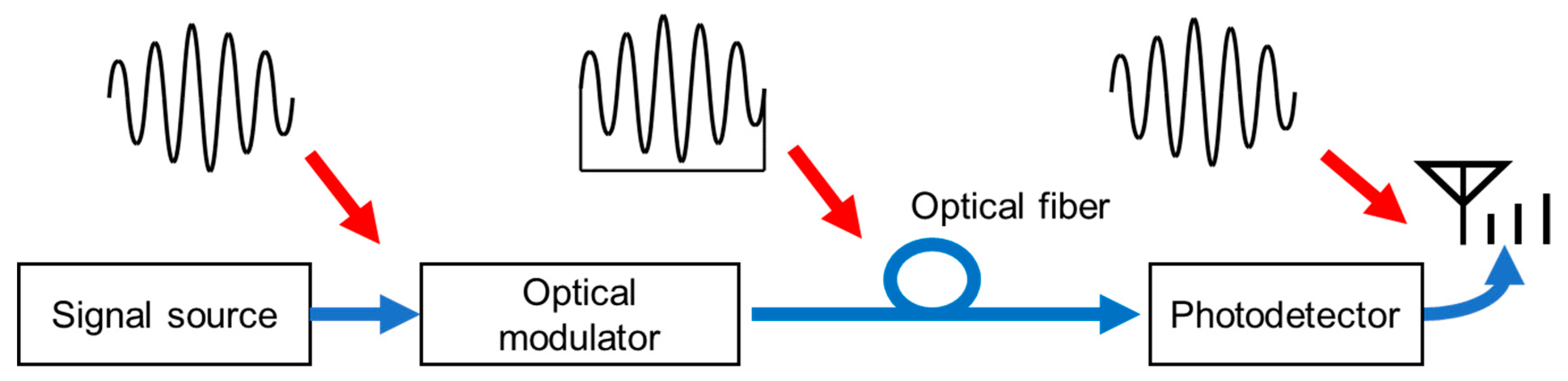
RoF (radio-over-fiber) technology consisting of electric-to-optical (EO) and optical-to-electric (OE) conversion devices provide the transfer of signal waveforms for radio services [9,10]. As shown in Figure 1, the EO and OE devices are connected through an optical fiber, where propagation loss in optical fibers would be much smaller than in metallic cables. If we used conventional metallic waveguides or cables for radio signal distribution, transmission loss would be particularly large for high-frequency signals. The loss largely depends on the signal frequency, while that of RoF systems with single mode fibers is almost constant when the transmission distance is shorter than 10 km. Total gain or loss of the RoF systems largely depends on EO and OE conversion efficiency, while the time domain waveform and spectrum of the radio-wave directly depends on preciseness of the conversion in the systems [11,12]. Most high-speed electro-optic devices were designed for high-speed digital transmission systems. In addition to high-speed operation, precise waveform control are required for RoF-based systems. Thus, the precise evaluation of components is very important in the fabrication of such RoF systems. Frequency response measurements for OE conversion devices have been demonstrated using a pure optical two-tone signal generated by high extinction-ratio optical modulation [13,14]. In RoF systems, broadband signal processing for radio-waves using state-of-the-art opto-electric devices including photonic crystal or micro-structured fibers can provide various optical signal processing approaches by dispersion and nonlinearity management [15,16,17,18,19,20].
This paper provides an outline of RoF systems and EO/OE devices for RoF. We describe a concept of linear cell radar systems having many antenna units with RoF to obtain linear-shaped coverage along optical fibers. The linear cell system can be applied to high-resolution imaging for airport runway surveillance and to high-speed wireless links for high-speed trains.
2. RoF System
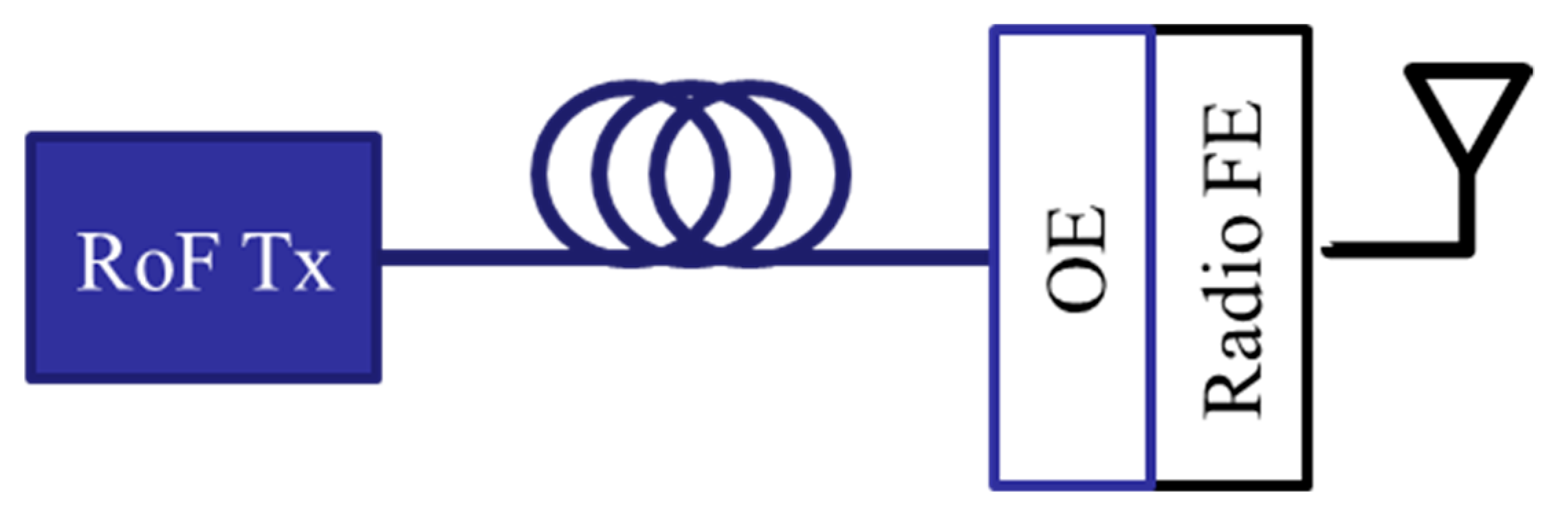
For future mobile services, such as beyond 5G or 6G, a huge number of antenna units are required to provide high-speed and low-latency radio services with large coverage, because available radio frequency resources are limited. Thus, the networks have many interfaces between optical and radio signals. Figure 2 shows a schematic of an interface between optical and radio links using a conventional digital transmission link. This interface is for radio-wave radiation. For radio-wave reception, we could use a similar setup. The interface should have an OE conversion device, digital signal processor (DSP), and radio front-end (FE). Data streams demodulated from optical signals generated by an optical transmitter (Tx) should be converted into radio-waveforms by the DSP. The reduction of complexity, power consumption, and latency in such interfaces is very important to minimize the system operation cost of future mobile networks. One possible solution for this issue is to use RoF, where a RoF Tx generates an optical signal for waveform generation at the radio FE, as shown in Figure 3.
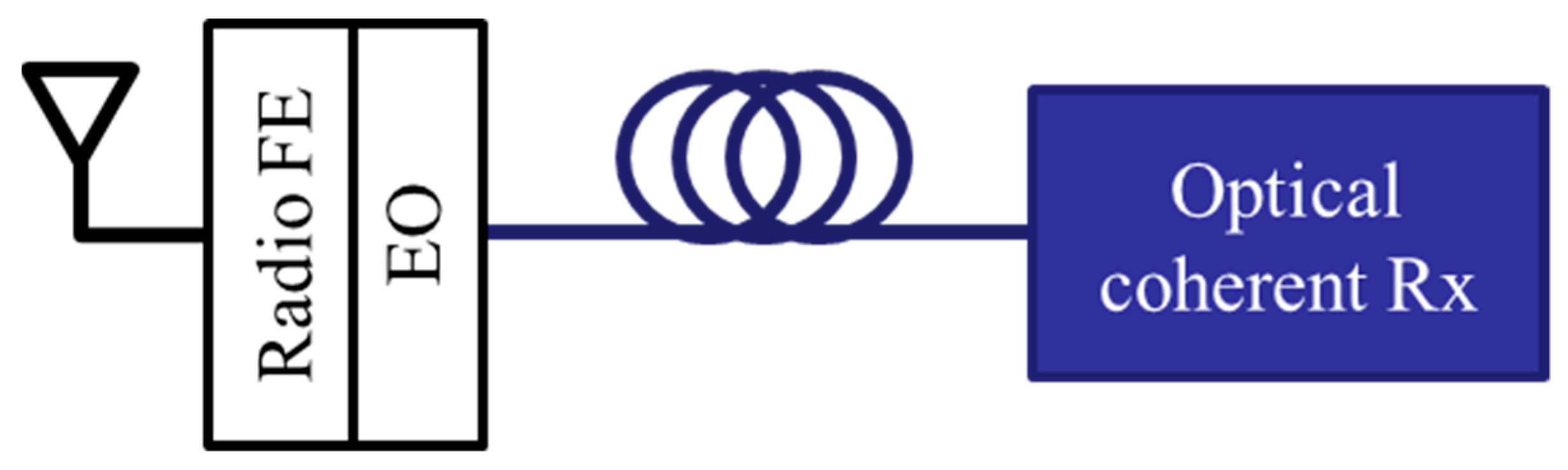
The optical signal carries IF (intermediate frequency) or RF (radio frequency) signal waveforms for radio signal generation. In IF-over-fiber systems, radio FEs should have local oscillators (LOs) for frequency conversion. For advanced modulation formats, we need low phase noise and stable sinusoidal forms as LO signals. RoF can also be used for the distribution of such sinusoidal waveforms to antenna units [9]. Figure 4 shows an example of RoF systems for radio-wave reception. Radio-waves received by an antenna were fed to the radio FE for frequency conversion or amplification. The dynamic range of RoF links is smaller than in electric conventional radio systems, so the proper design of automatic gain control (AGC) at the radio FE is very important to obtain high-performance radio transmission. Waveform deformation of optical signals in the fibers and radio signals in the air would be comprehensively compensated by optical coherent signal detection with DSP.
3. Photonic Devices for RoF Systems
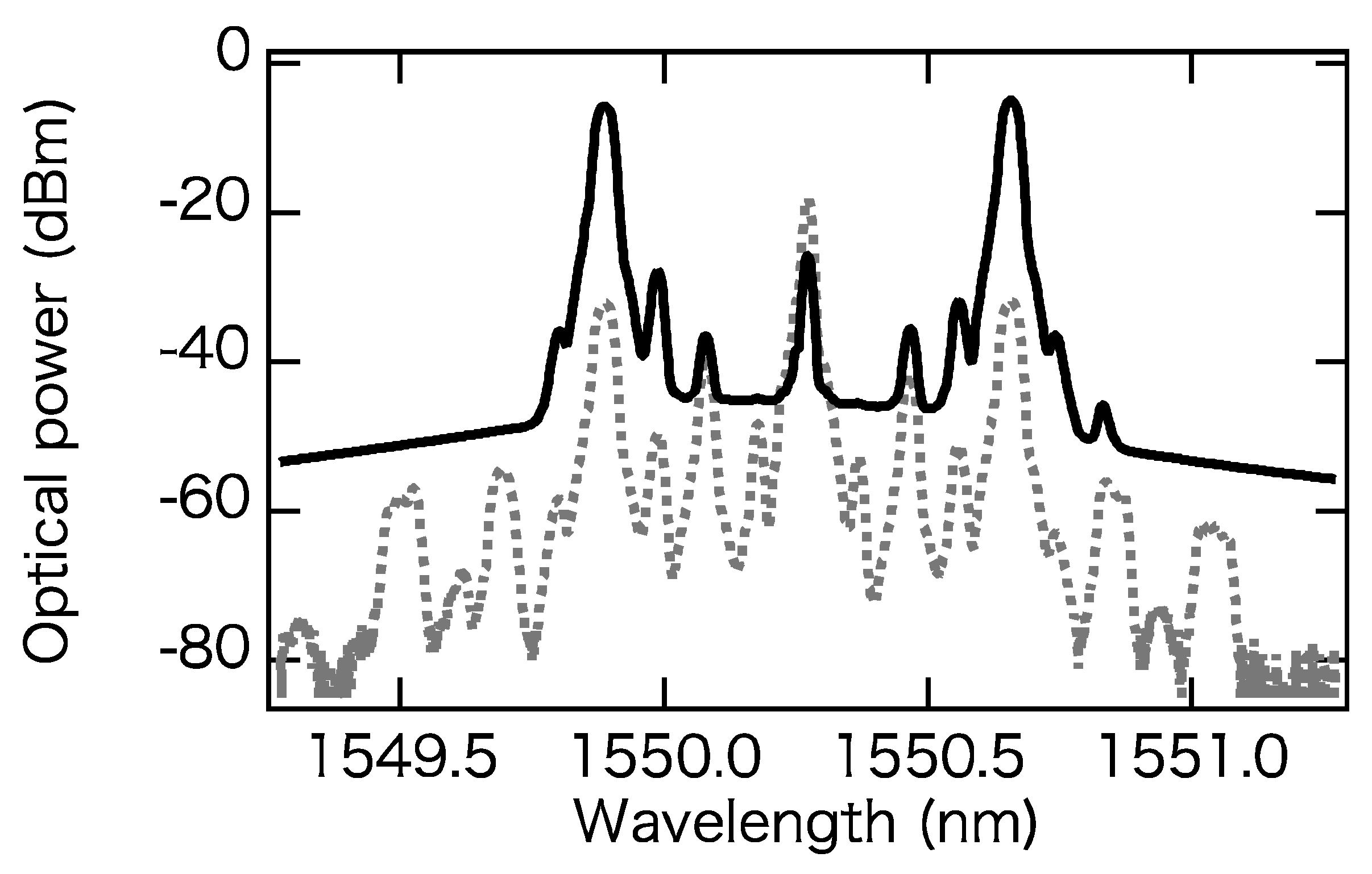
Frequency multiplication by optical modulation can easily generate and distribute millimeter-waves over optical fibers. For radio astronomy and RoF-based radars, frequency tunable sinusoidal signal generation is required for the synchronization of signal detection or LO signal distribution. As an example of such signal generation, a setup for frequency-modulated continuous-wave (FM-CW) signal generation with this optical modulation technique is shown in Figure 5 [21,22,23,24,25,26,27]. This was designed for W-band radar application [24]. A digital-to-analogue converter (DAC) generated a swept-frequency electric signal, whose start and stop frequencies were 359.375 MHz and 390.625 MHz, respectively. An FM-CW signal whose center frequency and frequency width were 24 GHz and 2GHz was generated by a series of frequency multipliers, where the sweep time was 1 μs. A lightwave-generated tunable laser diode (TLD) was fed to a Mach–Zehnder modulator (MZM) to obtain sidebands. The lightwave wavelength was 1550.03 nm. The DC (direct current) bias of the MZM was set to be a maximum transmission condition to maximize the carrier and second-order sidebands and to minimize the first-order sidebands. To suppress the carrier, we used an optical band eliminating filter (OBEF). The suppression ratio of the first-order sidebands depended on the extinction ratio (ER) of the MZM. We used a high-ER optical MZM to generate an optical signal, which had the upper and lower second-order sidebands as shown in Figure 6. The frequency separation between these two spectral components was 92–100 GHz. We also used an erbium-doped fiber amplifier (EDFA) and an optical band pass filter (OBPF) to boost the signal. The optical signal was fed to a photodetector to generate a W-band (92–100 GHz) frequency chirp signal, whose sweep rate was 8 × 10¹⁵ Hz/s.
Quantum dots (QDs) semiconductor devices can be applied to light sources and photodetectors for RoF systems. Due to quantum confinement, QD light source devices can provide high-speed and wide-wavelength operation. In addition to light source devices including QD lasers and QD semiconductor optical amplifiers (QD-SOAs), QD photodetectors (QD-PD) have been reported to investigate particular functions such as an avalanche effect inside QD layers [12,25,26,27]. In Reference [26], QD-PD with 20 stacked QD absorption layers was reported, where four InAs QDs monolayers and 20-nm-thick InGaAlAs spacer layers were grown on an InP substrate, by the use of molecular beam epitaxy via the strain-compensation technique. A PIN (p-i-n) structure with a 400-nm-thick active region was fabricated, where the QD density was 1.3 × 1012 cm−2. A QD-PD device with a large active area was fabricated to estimate responsivities, where the size of the area was 0.5 × 1.0 mm2. For current-voltage (I-V) curves and frequency, responses were measured using a fabricated device with a small active area whose diameter was 14 μm.
The absorption coefficient and responsivity of a fabricated InAs QD absorption layer was estimated with surface illumination, where an InGaAs bulk absorption layer was used for reference. Firstly, the estimated absorption coefficient of InGaAs was 1 × 104 cm−1, which was obtained from the measured responsivity of a 0.4-μm InGaAs layer. Calculated responsivity of a 24-nm InGaAs absorption layer was 0.015 A/W at 1550 nm. If the InAs QDs had the same absorption coefficient as InGaAs, that is, 1 × 104 cm−1, the expected measured responsivity would be approximately 0.015 A/W at a wavelength of 1550 nm. However, the measured responsivity of the QD layer was 0.055 A/W, which was three times higher than that of the InGaAs absorption layer, as shown in Figure 7. This implies that the absorption coefficient α was enhanced by the quantum confinement effect. Figure 8 shows I-V curves for the dark current and the photocurrent. The dark current was less than 1 nA when the reverse bias voltage was in the range from −10 to −20 V. The breakdown voltage of the I-V curve was as low as −28 V. The PIN-based QD structure allowed a photocurrent from low to high bias voltage. It functioned as a simple PIN photodiode at a low bias voltage and as an avalanche photodiode at a higher bias voltage. At over 20 V, we observed the avalanche multiplication effect, and a factor (M) of 12 with a dark current of 3 μA was achieved at −27.7 V. For the PIN photodiode at a low bias voltage, the 3 dB bandwidth (f3dB) was calculated from the capacitor-resistor (CR) time-constant and the carrier drift time in the depletion (QD) layer, where a measured capacitance of 36 fF and a resistance of 15 Ω in the network analyzer were used. We also used the saturated carrier-drift’s average velocity of electrons and holes in the QD layer and the traveling distance, which were 6 × 106 cm/s and 0.4 µm, respectively. The maximum calculated f3dB was approximately 50 GHz. However, we also obtained a f3dB value of 20 GHz (M = 1) at a low bias voltage, which was caused by a large parasitic capacitance between the n+-InP substrate and the electrodes, except at the p-n junction. By employing a semi-insulator substrate instead of the n+ substrate, we reduced the parasitic capacitance and hence improved the measured 3 dB bandwidth. In the avalanche multiplication region at a higher bias voltage, an additional multiplication time parameter should be taken into account for the PIN f3dB calculation. Because the prepared QD absorption layer had a multi-quantum well (MQW) structure, a small electron-to-hole ionization coefficient ratio (k factor) could be expected. From the AlGaAs/GaAs MQW avalanche photodiode, a small k factor of 0.12 was obtained owing to the large CB (conduction band) offset in the MQW boundary.
4. Linear Cell Radar Based on RoF [6,12]
For the safe operation of airport runways, foreign-object debris detection (FODD) is an indispensable activity. This system should be used to cover runways whose lengths are longer than a few kilometers. A typical runway width is 60 m. To ensure safe take-off and landing, small objects should be detected by high-resolution imaging. A standard FOD whose diameter and height are 1 inch each is defined to measure the performance of such imaging technologies. For the detection of such FOD, we can use various techniques including high-resolution cameras and lidars. However, their performance would be degraded in severe weather conditions such as fog and snow. The time duration for detection is also an important issue. Time intervals of take-offs and landings in busy airports would be 90 s, so the time duration for imaging should be shorter than 30 s to save time for air traffic controllers to make decisions. Millimeter-wave radars which can provide high-resolution imaging with a short time duration would be candidates for the detection of FOD [6,28,29,30]. In the millimeter-wave range, a wide spectrum may be used to achieve a range resolution of a few centimeters.
Bands with a frequency of 60 GHz attract much attention for unlicensed high-speed short-distance telecommunications. However, due to their large attenuation by oxygen, 60 GHz bands are not suitable for moderate distance applications. On the other hand, as shown in Figure 9, atmospheric attenuation in the range from 70 GHz to 110 GHz (E- and W-bands) is much smaller than that in 60 GHz bands. Dry air attenuation is the lowest at 94 GHz in the frequency region higher than 60 GHz. In this range, 92–100 GHz is internationally allocated for radio location services.
Even in the band from 92 GHz to 100 GHz, millimeter-wave attenuation in the air limits millimeter-wave radar coverage. High-power traveling wave tube amplifiers can be used to cover a runway by a radar unit. However, the high cost and short lifetime of the amplifiers are issues for reduction of operation cost.
In order to solve this issue, a radar system consisting of many antenna units connected by radio-over-fiber has been developed, where information collected at each antenna unit would be complied coherently at a central unit. Waveforms for radar operation are transferred by optical fibers between the antenna units and the central unit.
The system described in Figure 10 is called the linear cell radar system, which provides linear-shaped coverage by the use of linearly located antenna units. It is rather difficult to provide two-dimensional wide-area coverage using RoF links, because a huge number of links would be required. However, for one-dimensional service coverage, RoF systems with antenna units located along with optical fibers to form linear-shaped coverage would be feasible for applications in important public infrastructure such as airport runways, railways, motorways, etc. N units could cover an area N times longer, while a system with a radar unit needs at least an N4 times larger radiation power to achieve an N times longer range. A radar system consisting of many radar heads could largely reduce the total radiation power of the system and the required millimeter-wave output at each unit, so that the high-resolution imaging for long area coverage could be achieved by low-cost semiconductor devices.
A liner cell radar system using radio-over-fibers has been developed for FOD detection on runways [6,7]. The system uses FW-CW (frequency modulation continuous wave) radar technology, where the sweep range and center frequency of the transmitted FM signal were 7.9 GHz and 96 GHz, respectively. In Reference [28], the basic characteristics of a millimeter-wave FW-CW radar were estimated, where the range resolution was 8 cm.
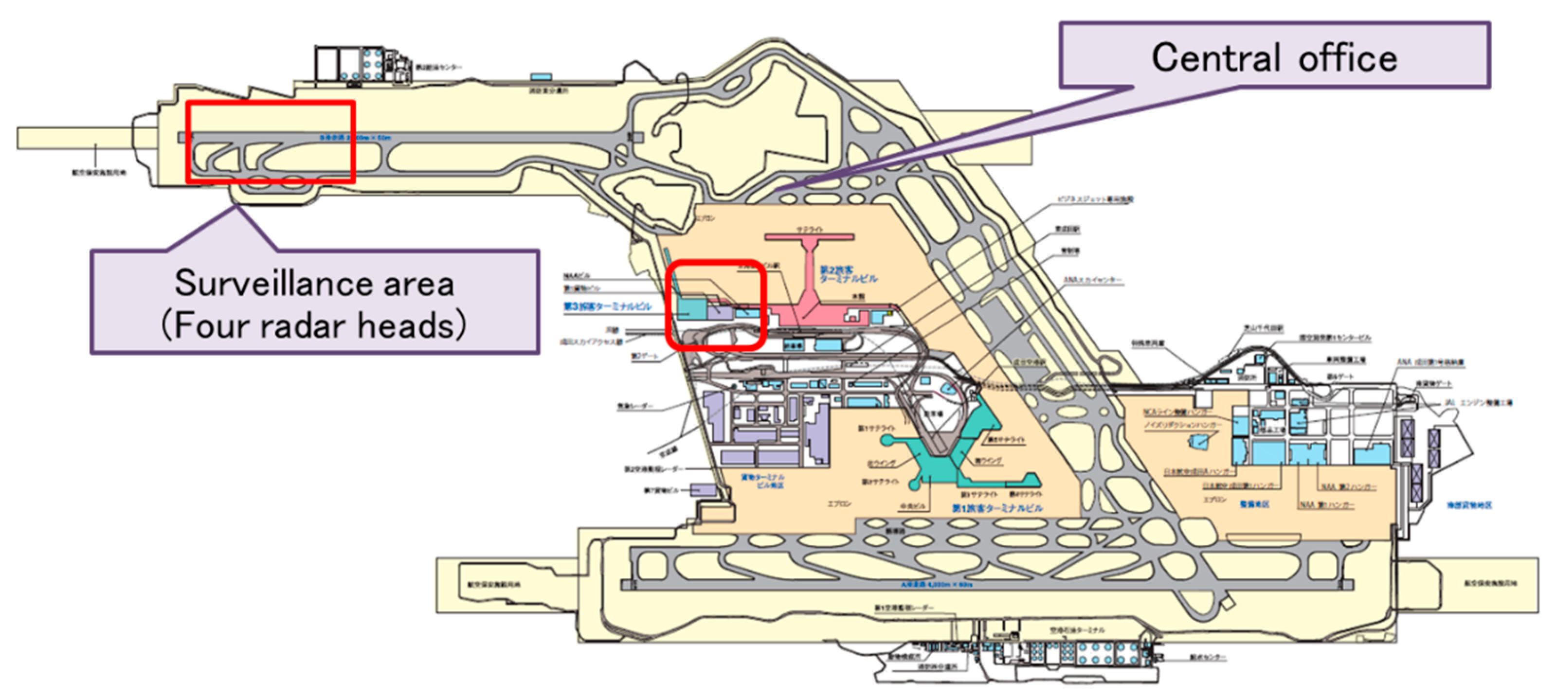
A field trial of our liner cell radar at a landing area of Narita International Airport (NRT) runway 34R is underway, where four radar heads are connected to a control unit located in a central office close to Terminal 2, as shown in Figure 11. The duration of the two-dimensional image measurement is 4s. Dispersion effect in the fibers whose lengths are less than 7 km have been successfully suppressed by the use of an optical two-tone signal generation, as described in Section 3. The optical signal is converted to W-band millimeter-wave signals by photodetectors as well as frequency multipliers and amplifiers. The radar system can detect metal objects whose radar cross-section is larger than −20 dBsm, within a distance of 460 m [6,7]. Figure 12 shows an example of radar images obtained by one of the radar units in the linear cell radar system at NRT. This was measured under light rain, so the radar detected reflected waves from splashes by an airplane on the runway, as well as that from runway edge lights. This implies the capability to perform agile and high-resolution imaging. Two-dimensional special resolution can be enhanced using plural radar units for a particular area in the runway. Now, another field trial at Kuala Lumpur International Airport (KLIA) is under preparation for comprehensive testing of the linear cell radar system.
5. Possible Interference in Linear Cell Radars [32]
Spectrum congestion in millimeter-wave bands are not yet severe; however, frequency bands are allocated to various radio services. In addition to remote sensing and radio astronomy, high-speed wireless data transmission technologies using 90 GHz bands have been actively developed for connecting high-speed trains and remote access units (RAUs). This implies that radio interference at 90 GHz would be an issue in the near future. In the linear cell radar system, comprehensive RAU control would be useful to suppress interference between the RAUs. The beam direction of each RAU could be controlled by a central control unit to avoid such interference. All the RAUs could be connected to the central control unit through optical fiber links. However, strong interference would occur, by strong radio-wave reflection from a smooth surface on an aircraft.
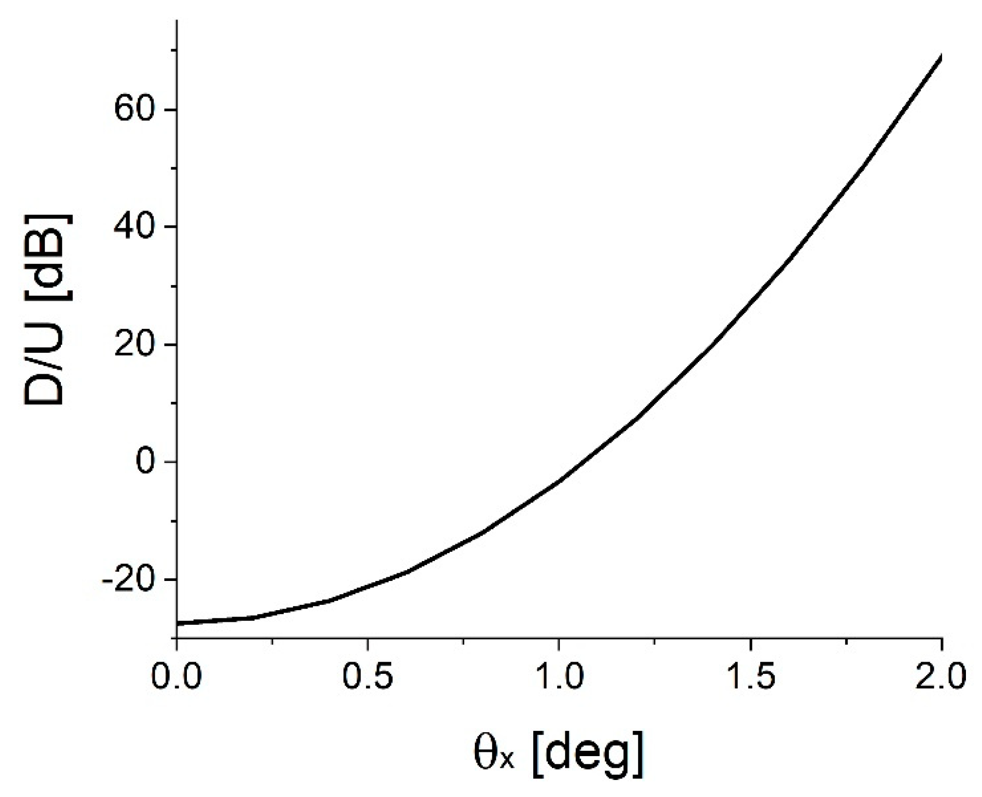
Figure 13 shows an interference model in a liner cell radar system to calculate the ratio of a desired signal from an FOD and an undesired signal from another RAU located at the opposite side of the runway. The beam cross-section was assumed to be Gaussian with a 1-degree FWHM (full width half maximum). The radar cross-section of the FOD was assumed to be −20 dBsm. Figure 14 shows the ratio between the desired and undesired signals (D/U ratio). The possibility of interference would be roughly estimated by this calculated D/U ratio. If the beam angle difference was smaller than 1 degree, the D/U ratio would be smaller than 0 dB. Thus, the angle difference between the RAUs should be larger than 1 degree to suppress the interference described in Figure 13.
Here, we discuss the possibility of interference due to stray beams generated by reflection on aircraft body surfaces. The angles and locations of such surfaces should be stochastic values, because they depend on the angles and locations of the aircrafts. For simplicity, their distributions are assumed to be uniform. An interfering beam from a surface illuminates a RAU with a particular azimuth angle illumination. The probability that the azimuth angle difference is smaller than 1 degree would be 1/360. The probability that aircrafts reflect the beams would be 0.05, when the time interval of landings and take-offs is 90 s. The average aircraft length and speed are respectively assumed to be 60 m and 50 km/h. If the antenna rotation period is 4 seconds, the false alarm rate per day would be approximately 3.2. The false rate would be 0.08, by taking into account the factors of shadowing and misalignment of elevation angle, which are assumed to be 1/4 and 1/10, respectively. A hybrid sensing system consisting of high-resolution cameras and radars can be used to reduce the false alarm rate. The direction of cameras would be controlled by information obtained by radars. In Reference [33], an interference mitigation technique was reported, where false images were suppressed by using various frequency sweep speeds for neighboring RAUs.
Author Contributions
Conceptualization and writing T.K.; device analysis T.U.; system analysis A.K. and P.T.D.; project administration, N.Y.
Funding
The research work reviewed in this paper was partially supported by the Japanese Government funding for “R&D to Expand Radio Frequency Resources” from the Ministry of Internal Affairs and Communications, and by JSPS KAKENHI Grant Number JP18H01454.
Acknowledgments
The authors would like to thank Nobuhiko Shibagaki, Kenichi Kashima, and Yosuke Sato of Hitachi Kokusai Electric Inc., Japan, Naruto Yonemoto of Electronic Navigation Research Institute, Japan, and Hiroyo Ogawa and Keizo Inagaki of the National Institute of Information and Communications Technology, Japan, for their collaboration with the experiments and their fruitful discussions. The linear cell radar field trial at NRT was supported by the Narita International Airport Cooperation (NAA), Japan.
Conflicts of Interest
The authors declare no conflict of interest. The funders had no role in the design of the study; in the collection, analyses, or interpretation of data; in the writing of the manuscript, or in the decision to publish the results.
References
- Qunyu, X.; Huansheng, N.; Weishi, C. Video-based Foreign Object Debris detection. In Proceedings of the 2009 IEEE International Workshop on Imaging Systems and Techniques, Shenzhen, China, 11–12 May 2009. [Google Scholar]
- Galati, G.; Piracci, E.G.; Ferri, M. High resolution, millimeter-wave radar applications to airport safety. In Proceedings of the 2016 8th International Conference on Ultrawideband and Ultrashort Impulse Signals (UWBUSIS), Odessa, Ukraine, 5–11 September 2016. [Google Scholar]
- Mehdi, G.; Miao, J. Millimeter wave FMCW radar for Foreign object debris (FOD) detection at airport runways. In Proceedings of the 2012 9th International Bhurban Conference on Applied Sciences & Technology (IBCAST), Islamabad, Pakistan, 9–12 January 2012. [Google Scholar]
- Wei, L.; Yahai, W.; Liuge, D. FODs detection system based on millimeter wave FMCW radar. In Proceedings of the 2013 IEEE 11th International Conference on Electronic Measurement & Instruments, Harbin, China, 16–19 August 2013. [Google Scholar]
- Marron, J.C.; Schroeder, K.S. Holographic laser radar. Opt. Lett. 1993, 18, 385–387. [Google Scholar] [CrossRef] [PubMed]
- Kawanishi, T.; Kanno, A.; Yamamoto, N. 90-GHz Linear-Cell Systems for Public Transportation Systems. In Proceedings of the 2018 20th International Conference on Transparent Optical Networks (ICTON), Bucharest, Romania, 1–5 July 2018. [Google Scholar]
- Kawanishi, T. Millimeter-wave Radars Using Radio-over-fibers. In Proceedings of the 2018 IEEE Photonics Conference (IPC), Reston, VA, USA, 30 September–2 October 2018. [Google Scholar]
- Yonemoto, N.; Kohmura, A.; Futatsumori, S.; Uebo, T.; Saillard, A. Broad band RF module of millimeter wave radar network for airport FOD detection system. In Proceedings of the Intl. Radar Conf. Surveillance for a Safer World, Bordeaux, France, 12–16 October 2009. [Google Scholar]
- APT Report on “Wired and Wireless Seamless Connections Using Millimeter-Wave Radio over Fiber Technology for Resilient Access Networks”. APT/ASTAP/REPT-11. Available online: https://www.apt.int/aptastap-outcomes (accessed on 6 February 2019).
- Kawanishi, T.; Kanno, A.; Kuri, T.; Yamamoto, N. Transparent waveform transfer for resilient and low-latency links. IEEE Photonics Soc. Newslett. 2014, 28, 4–8. [Google Scholar]
- APT Report on “Characteristics and Requirements of Optical and Electrical Components for Millimiter-Wave Radio on Fiber Systems”. APT/ASTAP/REPT-03 (Rev.4). Available online: https://www.apt.int/aptastap-outcomes (accessed on 6 February 2019).
- Kawanishi, T.; Yamamoto, N.; Umezawa, T.; Akahane, K.; Kanno, A.; Dat, P.T. Electro-optic devices for imaging. In Proceedings of the 2014 16th International Conference on Transparent Optical Networks (ICTON), Graz, Austria, 6–10 July 2014. [Google Scholar]
- IEC 62803:2016. Transmitting Equipment for Radiocommunication—Frequency Response of Optical-To-Electric Conversion Device in High-Frequency Radio over Fibre Systems—Measurement Method; IEC: Geneva, Switzerland, 2016. [Google Scholar]
- Inagaki, K.; Kawanishi, T.; Izutsu, M. Optoelectronic frequency response measurement of photodiodes by using high-extinction ratio optical modulator. IEICE Electron. Express 2012, 9, 220–226. [Google Scholar] [CrossRef]
- Monfared, Y.E.; Javan, A.R.M.; Kashani, A.R.M. Confinement loss in hexagonal lattice photonic crystal fibers. Optik Int. J. Light Electron. Opt. 2013, 124, 7049–7052. [Google Scholar] [CrossRef]
- Guo, W.; Kou, J.; Xu, F.; Lu, Y. Ultra-flattened and low dispersion in engineered micro fibers with highly efficient nonlinearity reduction. Opt. Express 2011, 19, 15229–15235. [Google Scholar] [CrossRef] [PubMed]
- Monfared, Y.E.; Mojtahedinia, A.; Javan, A.R.M.; Kashani, A.R.M. Highly nonlinear enhanced-core photonic crystal fiber with low dispersion for wavelength conversion based on four-wave mixing. Front. Optoelectron. 2013, 6, 297–302. [Google Scholar] [CrossRef]
- Monfared, Y.E.; Ponomarenko, S.A. Extremely nonlinear carbon-disulfide-filled photonic crystal fiber with controllable dispersion. Opt. Mater. 2019, 88, 406–411. [Google Scholar] [CrossRef]
- Sintov, Y.; Malka, D.; Zalevsky, Z. Prospects for diode pumped alkali atom based hollow core photonic crystal fiber lasers. Opt. Lett. 2014, 39, 4655–4658. [Google Scholar] [CrossRef] [PubMed]
- Malka, D.; Cohen, E.; Zalevsky, Z. Design of 4 × 1 power beam combined based on multicore photonic crystal fiber. Appl. Sci. 2017, 7, 695. [Google Scholar] [CrossRef]
- Kanno, A.; Kawanishi, T. Optical FM-CW signal generation for millimeter-wave and optical imaging. In Proceedings of the International Topical Meeting on Microwave Photonics (MWP), Alexandria, VA, USA, 28–31 October 2013; pp. 108–111. [Google Scholar]
- Kawanishi, T.; Sakamoto, T.; Izutsu, M. High-speed control of lightwave amplitude, phase, and frequency by use of electrooptic effect. J. Sel. Top. Quantum Electron. 2007, 13, 79–91. [Google Scholar] [CrossRef]
- Kanno, A.; Kawanishi, T. Optical FM-CW signal generation for millimeter-wave imaging and OFDR applications. In Proceedings of the IEEE Avionics Fiber-Optics and Photonics Conference, San Diego, CA, USA, 1–3 October 2013. [Google Scholar]
- Kanno, A.; Kawanishi, T. 8-GHz-bandwidth FM-CW signal generation based on optical modulation technology for W-band radar system. In Proceedings of the European Radar Conference, Nuremberg, Germany, 9–11 October 2013; pp. 61–64. [Google Scholar]
- Umezawa, T.; Akahane, K.; Kanno, A.; Kawanishi, T. Characterization of APD- PIN photodiodes using InAs/InAlGaAs quantum-dot absorption layer. In Proceedings of the CLEO, San Jose, CA, USA, 9–14 June 2013. [Google Scholar] [CrossRef]
- Umezawa, T.; Akahane, K.; Kanno, A.; Kawanishi, T. Investigation of a 1.5-µm-wavelength InAs-quantum-dot absorption layer for high-speed photodetector. Appl. Phys. Express 2014, 7, 032201. [Google Scholar] [CrossRef]
- Akahane, K.; Yamamoto, N.; Kawanishi, T. Fabrication of ultra-high-density InAs quantum dots using the strain-compensation technique. Phys. Status Solid A 2011, 208, 425–428. [Google Scholar] [CrossRef]
- Kawanishi, T.; Yonemoto, N.; Shibagaki, N.; Kashima, K.; Haramoto, R.; Kanno, Y.S.A.; Inagaki, K.; Angkaew, T.; Janpugdee, P. Field trial of radio-over-fiber based high-resolution radar. In Proceedings of the 2015 Thailand-Japan Microwave (TJMW2015), Bangkok, Thailand, 6–8 August 2015. [Google Scholar]
- Kawanishi, T.; Kanno, A.; Yamamoto, N.; Yonemoto, N.; Shibagaki, N.; Kashima, K. Optical fiber network-connected distributed mm-wave radar system. In Proceedings of the 2017 IEEE Photonics Society Summer Topicals, San Juan, Puerto Rico, 10–12 July 2017. [Google Scholar]
- Kawanishi, T.; Kanno, A.; Freire, H.S.C. Wired and wireless links to bridge networks: Seamlessly connecting radio and optical technologies for 5G Networks. IEEE Microw. Mag. 2018, 19, 102–111. [Google Scholar] [CrossRef]
- Kawanishi, T.; Kanno, A.; Dat, P.T.; Yamamoto, N. Radio-over-fibre based high-speed millimetre-wave backhaul system for high-speed trains. In Proceedings of the 2016 18th International Conference on Transparent Optical Networks (ICTON), Trento, Italy, 10–14 July 2016. [Google Scholar]
- Kawanishi, T.; Akama, K.; Kanno, A.; Yamamoto, N. Linear cell radar system using radio-over-fiber links. In Proceedings of the IEEE Conference on Antenna Measurement and Applications (CAMA), Västerås, Sweden, 3–6 September 2018. [Google Scholar]
- Akama, K.; Kanno, A.; Inagaki, K.; Kawanishi, T. Interference mitigation in linear cell FOD radar by using FMCW signal source with different sweep speed. In Proceedings of the 5th ENRI International Workshop on ATM/CNS (EIWAC 2017), Tokyo, Japan, 14–16 November 2017. [Google Scholar]
Figure 1.
Schematic of a radio-over-fiber (RoF) system.

Figure 2.
Configuration of conventional optical-to-radio interface for radio-wave radiation.

Figure 3.
Configuration of RoF optical-to-radio interface for radio-wave radiation.

Figure 4.
Configuration of RoF optical-to-radio interface for radio-wave reception.

Figure 5.
Setup for W-band frequency-modulated continuous-wave (FM-CW) signal generation [12].
Figure 5.
Setup for W-band frequency-modulated continuous-wave (FM-CW) signal generation [12].

Figure 6.
Optical spectra of optical FM-CW signals consisting of the upper and lower sidebands of the Mach–Zehnder modulator (MZM) output (gray thin line) and at the optical band pass filter (OBPF) output (black solid line) [12].
Figure 6.
Optical spectra of optical FM-CW signals consisting of the upper and lower sidebands of the Mach–Zehnder modulator (MZM) output (gray thin line) and at the optical band pass filter (OBPF) output (black solid line) [12].

Figure 7.
Responsivity of the surface-illuminated InAs quantum dots (QDs) and InGaAs [12].
Figure 7.
Responsivity of the surface-illuminated InAs quantum dots (QDs) and InGaAs [12].

Figure 8.
Current-voltage (I-V) curves for the dark current and photocurrent with avalanche multiplication [12].
Figure 8.
Current-voltage (I-V) curves for the dark current and photocurrent with avalanche multiplication [12].
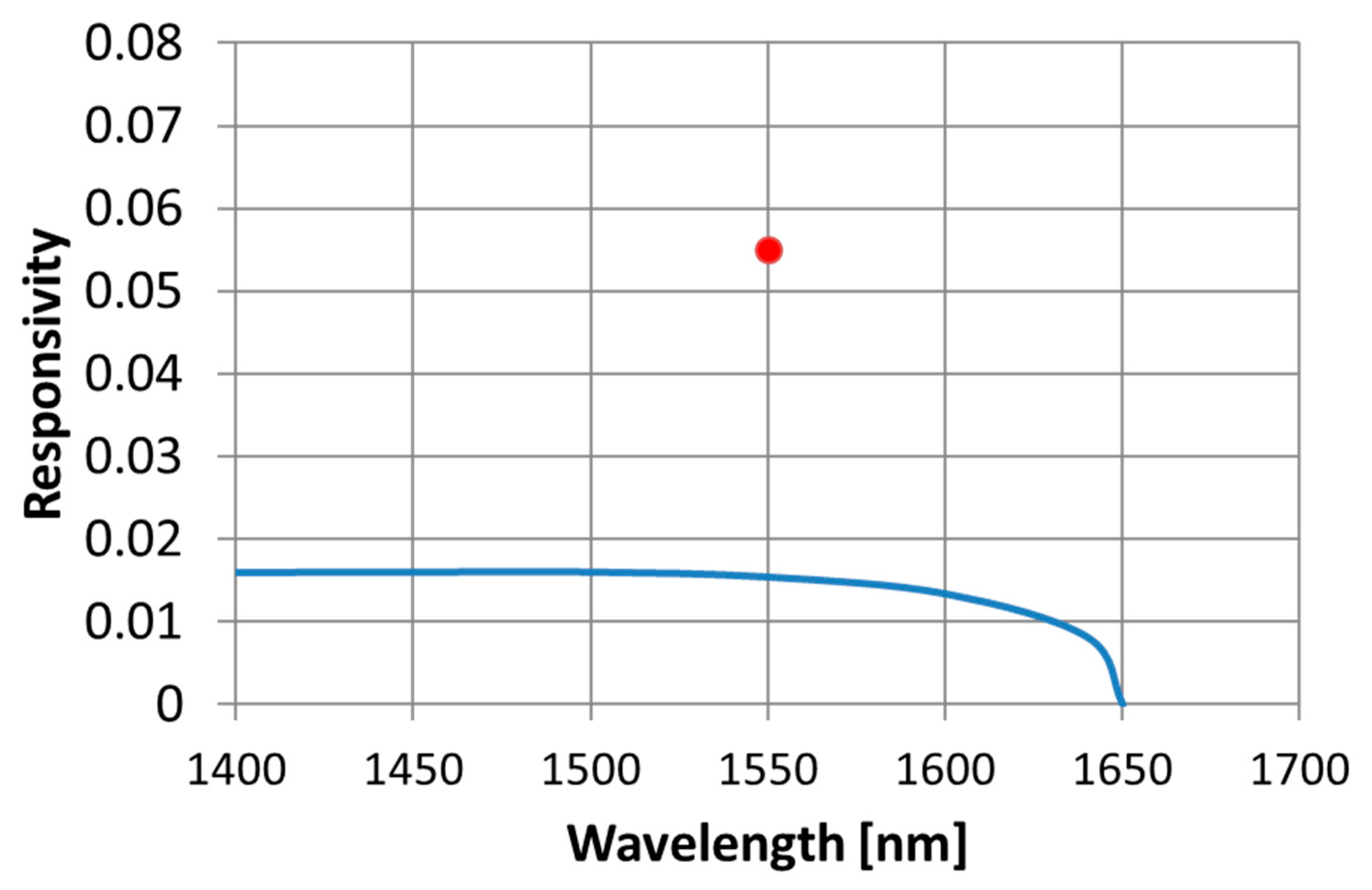
Figure 9.
Atmospheric attenuation of the millimeter-wave range [31].
Figure 9.
Atmospheric attenuation of the millimeter-wave range [31].

Figure 10.
Configuration of a linear cell radar [32].
Figure 10.
Configuration of a linear cell radar [32].
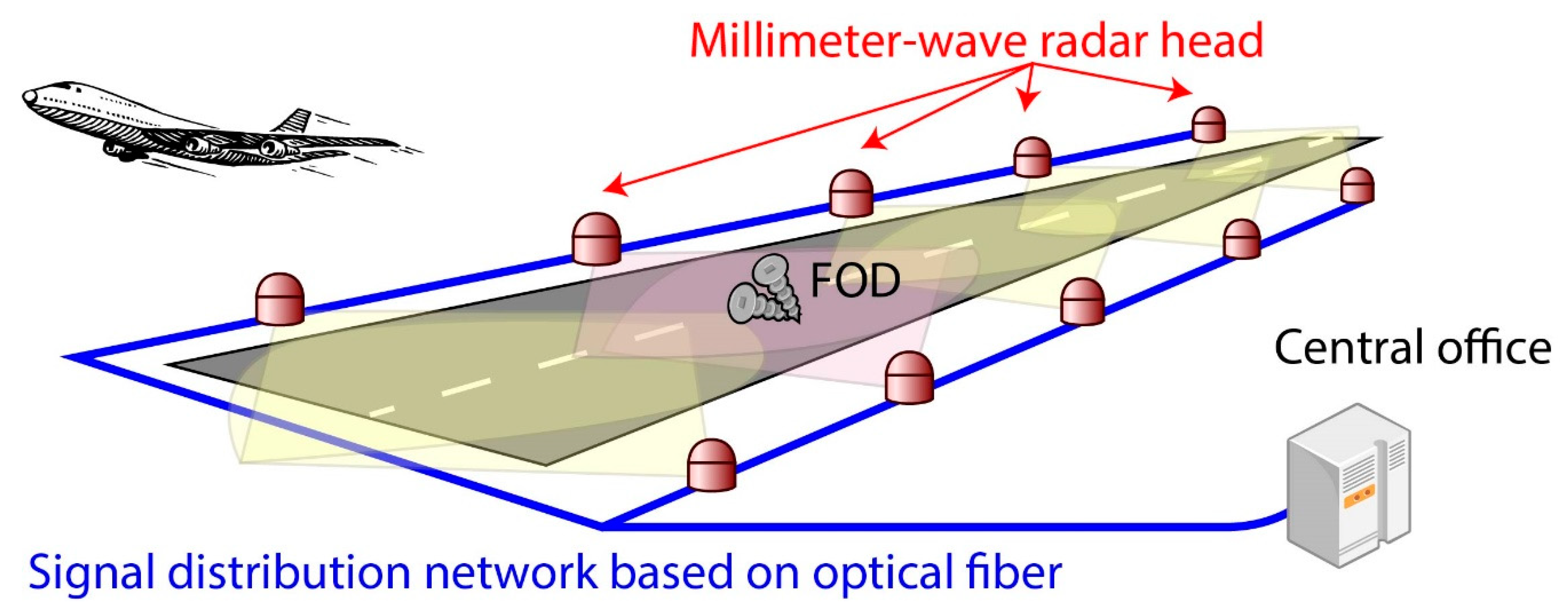
Figure 11.
Field trial at Narita International Airport [6].
Figure 11.
Field trial at Narita International Airport [6].

Figure 12.
Linear cell radar image [6].
Figure 12.
Linear cell radar image [6].

Figure 13.
Interference model [32].
Figure 13.
Interference model [32].

Figure 14.
Desired and undesired signal (D/U) ratio [32].
Figure 14.
Desired and undesired signal (D/U) ratio [32].

© 2019 by the authors. Licensee MDPI, Basel, Switzerland. This article is an open access article distributed under the terms and conditions of the Creative Commons Attribution (CC BY) license (http://creativecommons.org/licenses/by/4.0/).
Share and Cite
MDPI and ACS Style
Kawanishi, T.; Kanno, A.; Tien Dat, P.; Umezawa, T.; Yamamoto, N. Photonic Systems and Devices for Linear Cell Radar. Appl. Sci. 2019, 9, 554. https://doi.org/10.3390/app9030554
AMA Style
Kawanishi T, Kanno A, Tien Dat P, Umezawa T, Yamamoto N. Photonic Systems and Devices for Linear Cell Radar. Applied Sciences. 2019; 9(3):554. https://doi.org/10.3390/app9030554
Chicago/Turabian StyleKawanishi, Tetsuya, Atsushi Kanno, Pham Tien Dat, Toshimasa Umezawa, and Naokatsu Yamamoto. 2019. "Photonic Systems and Devices for Linear Cell Radar" Applied Sciences 9, no. 3: 554. https://doi.org/10.3390/app9030554
Note that from the first issue of 2016, this journal uses article numbers instead of page numbers. See further details here.