Cutting Performance and Wear/Damage Characteristics of PCBN Tool in Hard Milling

School of Mechanical and Power Engineering, Harbin University of Science and Technology, Harbin 150080, China
*
Author to whom correspondence should be addressed.
Appl. Sci. 2019, 9(4), 772; https://doi.org/10.3390/app9040772
Submission received: 6 January 2019
/
Revised: 12 February 2019
/
Accepted: 19 February 2019
/
Published: 22 February 2019
(This article belongs to the Special Issue Multiscale Fatigue Design)
Abstract
:In the intermittent machining of hardened steel for the die and mold industry, determining how to reduce the wear of PCBN (Polycrystalline Cubic Boron Nitride) tools and improve their machining efficiency and quality is an important subject. This study investigated the intermittent machining of hardened steel (Cr12MoV, 59HRC (Rockwell hardness)) using uncoated PCBN tools to determine the cutting performance (cutting force, chip morphology, surface quality, tool life, cutting temperature) and the wear/damage characteristics of the tools. The results showed that the cutting performance of a PCBN tool was better than that of a cemented carbide tool. The wear mechanism on the PCBN tool flank was diffusion wear, adhesive wear, and oxidation wear. The main failure modes of the PCBN tool in the machining process of hardened steel at low speed were tool micro-chipping, the conchoidal damage of the rake face, and the larger damaged area of the flank face. The main failure modes of the PCBN tool in the machining process of hardened steel at high speed were flank wear and high-rate fatigue damage.
1. Introduction
PCBN is a cutting tool material most widely used in the machining of hardened steel due to its higher hardness, strength, thermal and chemical stability, and thermal conductivity, and lower friction coefficient than other tool materials at high temperature [1,2,3]. Cutting performance and wear characteristics of PCBN tools were extensively studied in the hardened-steel cutting process.
During continuous and intermittent turning, the cutting performance and wear mechanism of PCBN tools were extensively studied. The cutting performance of PCBN tools with different CBN (Cubic Boron Nitride) content was investigated [4]. It was found that PCBN tools with low CBN content had better cutting performance than that of PCBN with high CBN content. The influence of chamfering angle on the cutting performance of PCBN tools was investigated [5,6,7]. It was found that the chamfering angle could effectively reduce cutting force, flank wear, and white layer thickness. Özel et al. [8] investigated the cutting performance of PCBN tools with variable micro-geometry in hard turning AISI4340 steel. It was found that the variable micro-geometry PCBN tool could effectively reduce cutting heat, plastic deformation of workpiece, and tool wear. The effect of the microstructure of hardened steel on the PCBN tool wear was investigated [9,10]. In addition, the effects of new tool materials [11] and high-pressure cooling technology [12] on the cutting performance of PCBN tools were studied. The main wear mechanism of PCBN tools in continuous and intermittent cutting of hardened steel (1117 steel, HRC62+1) was abrasive wear [13]. The main wear mechanism of PCBN tools in intermittent turning of bearing steel (AISIE-52100, HRC60) was abrasive wear and adhesion wear [14]. The main wear mechanism of PCBN tools in continuous and intermittent cutting of hardened steel (AISI 4340, HRC56) was abrasive wear [15]. Under high-pressure cooling conditions, PCBN inserts primarily sustain adhesive wear, groove wear, and abrasive wear on the flank face when cutting GH4169 [12]. Tang et al. [16] studied the effect of quenching hardness on the wear properties of PCBN tools for dry hard turning. The results showed that the wear mechanism of tool flank was abrasive wear in the cases of 40–55 ± 1 HRC and abrasive and delamination wear in the case of 60 ± 1 HRC. The wear mechanism of PCBN tools was abrasive wear in the machining of high-chromium white cast iron [17,18].
There were a few studies on the cutting performance and wear mechanism of PCBN tools in the milling process. Gopalsamy et al. [19] carried out an experimental study on end milling of DIEVAR hardened steel (50 HRC) with PCBN tools. The results indicated that the PCBN tool gave excellent performance in terms of tool life and surface finish in comparison with carbide-coated tools. Wojciechowski et al. [20] investigated the life of PCBN tools in milling die steel. The results showed that the tool life was affected by the cutting speed. Okada et al. [21] studied the cutting force, cutting temperature, tool wear, and surface roughness of PCBN tools with different CBN content in hard milling hardened steel. It was found that PCBN tools with high CBN content had higher cutting performance. Elbestawi et al. [22] investigated the wear properties of PCBN ball-end milling cutters with different CBN content in high-speed milling hardened AISI H13 die steel. It was found that the main wear forms of PCBN ball-end milling cutters with 90% CBN and 65% CBN were flank wear and chipping, respectively. Boing et al. [23] proposed a three-dimensional wear parameter method based on a focal-length change microscope to evaluate PCBN tool wear and wear mechanism. It was found that there was a nonlinear relationship between abrasive wear, adhesive wear, and diffusion wear, and material hardness. Its calculated results were nearly the same as those given by Luo et al. [24]. Saketi et al. [25] investigated the wear properties of PCBN tool with high CBN content in milling hardened steel. It was found that tribochemical reactions, adhesive wear, and mild abrasive wear controlled the flank and crater wear. Cui et al. [26] investigated the failure mechanism of PCBN tools in milling hardened steel based on damage equivalent stress.
By analyzing the above literature, it was found that chip morphology and cutting temperature were rarely used to evaluate the cutting performance of PCBN tools, whether in turning or milling of hardened steel. Two or three evaluation indicators were often selected to evaluate the cutting performance of PCBN tools in the existing literature. Cutting is a very complex process, and comprehensive evaluation indicators can more accurately reflect the cutting performance of PCBN tools. In the machining of hardened steel, the wear mechanism of PCBN tools varies with the material and hardness of the workpiece. At present, there is no research on the wear mechanism of PCBN tools in the intermittent machining of hardened steel (Cr12MoV, 59HRC). Meanwhile, the research on the damage characteristics of PCBN tools in the intermittent machining of hardened steel is still blank, which limits the application of PCBN tools. In this study, the cutting performances (cutting force, chip morphology, surface quality, tool life, cutting temperature) and the wear/damage characteristics of PCBN tools were investigated for the intermittent machining of hardened steel.
2. Experimental Set-Up
2.1. Experimental Conditions
The hardened die steel material used in the experiment was Cr12MoV. The workpiece was 120 × 70 × 70 mm. The work material was hardened and tempered to 59 HRC. The chemical compositions of the die steel are shown in Table 1. The physical properties of the die steel are shown in Table 2. The cutter used in the experiment was the ball-type-head clamping milling cutter. The cemented carbide tool was BNM-200 JC5015 (Daijie Company, Osaka, Japan, 2018) with a diameter of 20 mm. The coating film material of the cemented carbide tool was TiAlN. Physical properties of coating film materials for cemented carbide tool are shown in Table 3 [21]. Physical properties of base materials (K10, Co content 6%, WC (Wolfram Carbide) grain size 2 μm) are shown in Table 4. The uncoated PCBN tool used in the experiment was DCC500 (Element Six Company, Didcot, Britain, 2018) with a diameter of 20 mm. PCBN tools were composed of a CBN content of 45%, a TiC bonding agent, and a grain size of 1.5 μm. The geometric parameters of the two cutters were rake angle 0°, clearance angle 13°, chamfer width 0.1 mm, and chamfer angle 15°. The cutting mode was down milling. The tool used in the experiment is shown in Figure 1. The experiment was carried out on a three-axis machining center with the model VDL-1000E (Dalian machine tool group, Dalian, Liaoning, China, 2005). The experimental site is shown in Figure 2.
2.2. Experimental Scheme
The experimental scheme for exploring the cutting performance of the PCBN tool and cemented carbide tool is shown in Table 5. The force in the cutting process was measured using a three-way piezoelectric dynamometer 9257B (Swiss KISTLER company, Winterthur, Switzerland, 2015). The free surface morphology of the chip was observed by SEM with SUPRA 55 (Karl Zeiss, Oberkochen, Germany, 2018). The macroscopic morphology of the chip and the tool wear state were observed using a super-deep-scene three-dimensional (3D) microscope with VHX-1000 (KEYENCE, Osaka, Japan, 2009). A portable surface roughness measuring instrument was used to measure the roughness of the machined surfaces of two kinds of cutters at the same distance. For cemented carbide tools, the cutting lengths of each cutting parameter in test 1 were 16,720 mm, 27,600 mm 76,000 mm, and 33,600 mm. For PCBN tools, the cutting lengths of each cutting parameter in test 1 were 400 mm, 33,840 mm, 98,400 mm, and 154,560 mm. The cutting length of each cutting parameter in test 4 was 20,000 mm. The cutting length of each cutting parameter in other tests was 1200 mm.
3. Experimental Analysis
3.1. Milling Force
Thermal load and mechanics loads affect tool life and machined surface integrity. Because of the characteristics of milling, it is difficult to measure the cutting heat, but the cutting force can be easily obtained. Therefore, the cutting force measured by experiment was selected to evaluate the cutting performance of the tool.
(1) Cutting Speed (Test 1)
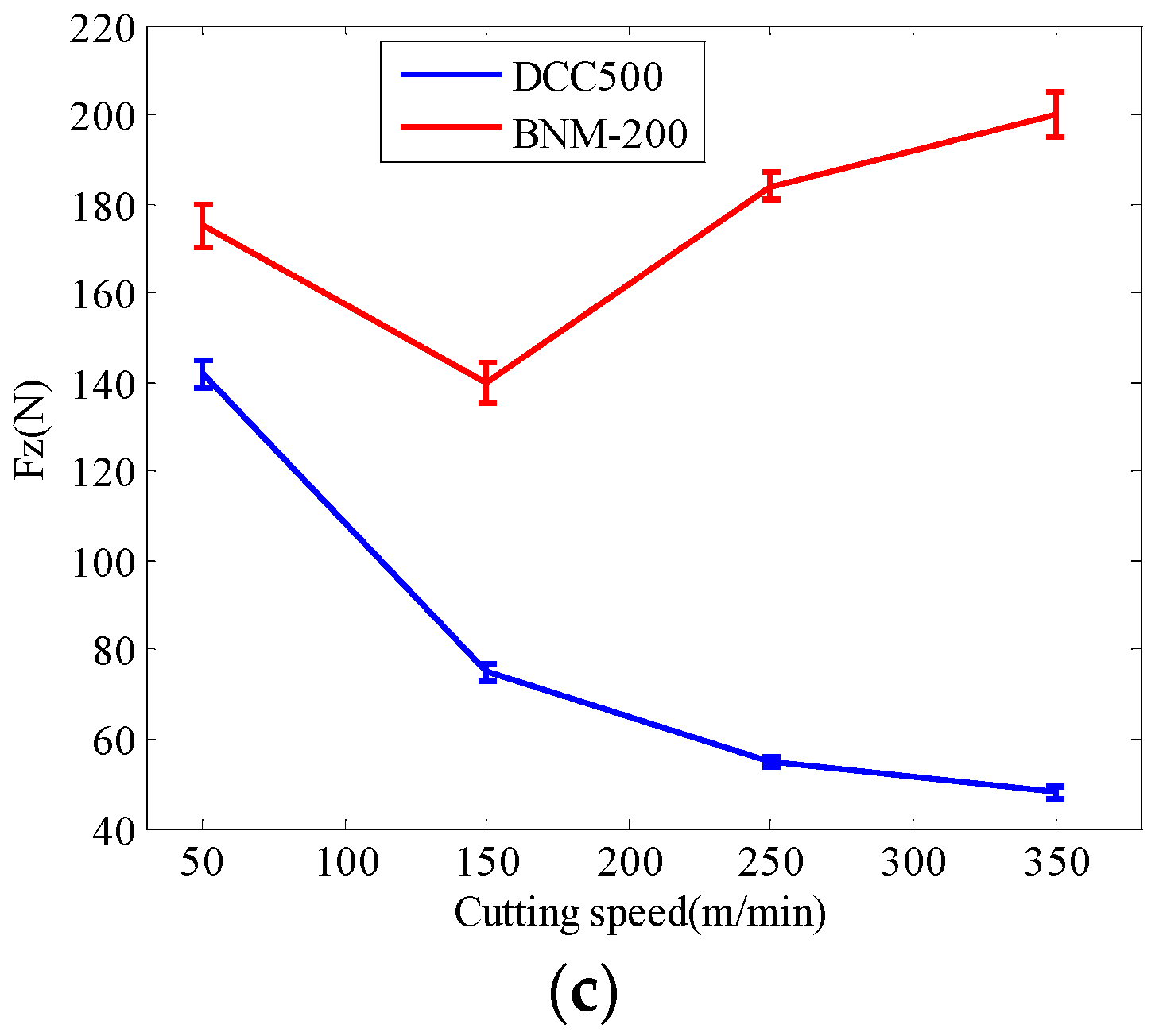
The influence of cutting speed on the cutting force of the two kinds of cutting tools is shown in Figure 3.
When the cutting speed exceeded 150 m/min, the cutting force increased rapidly for the cemented carbide tool (BNM-200). The main reason was that, when the cutting speed was high, the cutting temperature rose rapidly. The cemented carbide tool cannot withstand high temperature, which results in a large degree of wear and even edge chipping. With the increase of cutting speed, the cutting performance of PCBN tools (DCC500) can be better reflected. The cutting force in three directions decreased gradually with the increase of cutting speed. The reason was that, with the increase of cutting speed, the temperature of the cutter–chip contact area increased, which made the workpiece material produce a thermal softening effect.
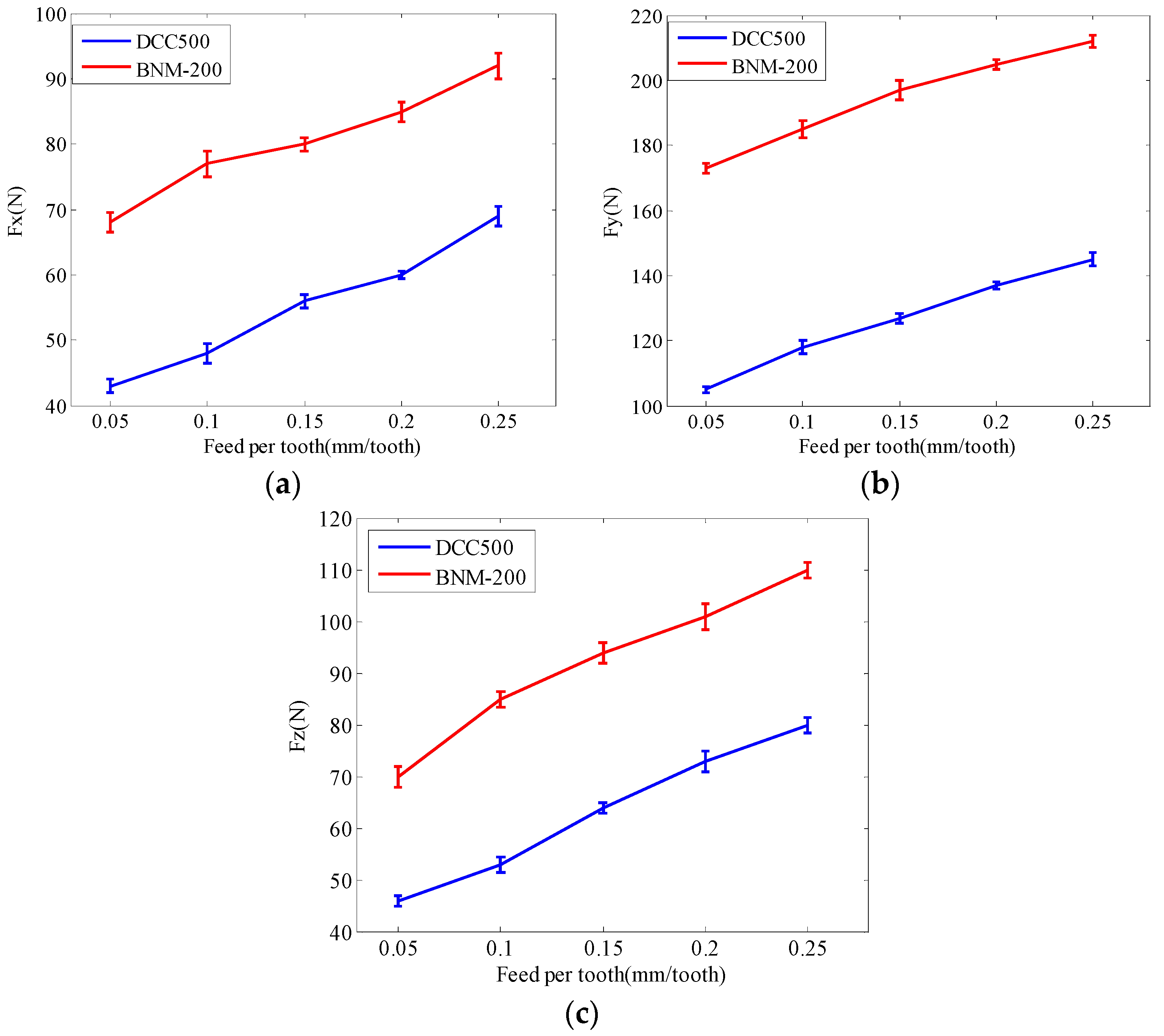
(2) Feed per Tooth (Test 2)
The influence of feed per tooth on the cutting force of the two kinds of cutting tools is shown in Figure 4. The cutting force of the two cutters increased with the increase of feed per tooth. The reason was that the metal removal rate increased with the increase of feed per tooth. The cutting force of the PCBN tool (DCC500) was less than that of the carbide tool (BNM-200).
(3) Axial Depth of Cut (Test 3)
The influence of axial depth of cut on the cutting force of the two kinds of cutting tools is shown in Figure 5. The cutting force of the two cutters increased with the increase of axial depth of cut. The reason was that the metal removal rate increased with the increase of axial depth of cut. Compared with cemented carbide cutting tools (BNM-200), PCBN cutting tools (DCC500) had a gentle trend of change in cutting force and higher stability.
3.2. Surface Quality
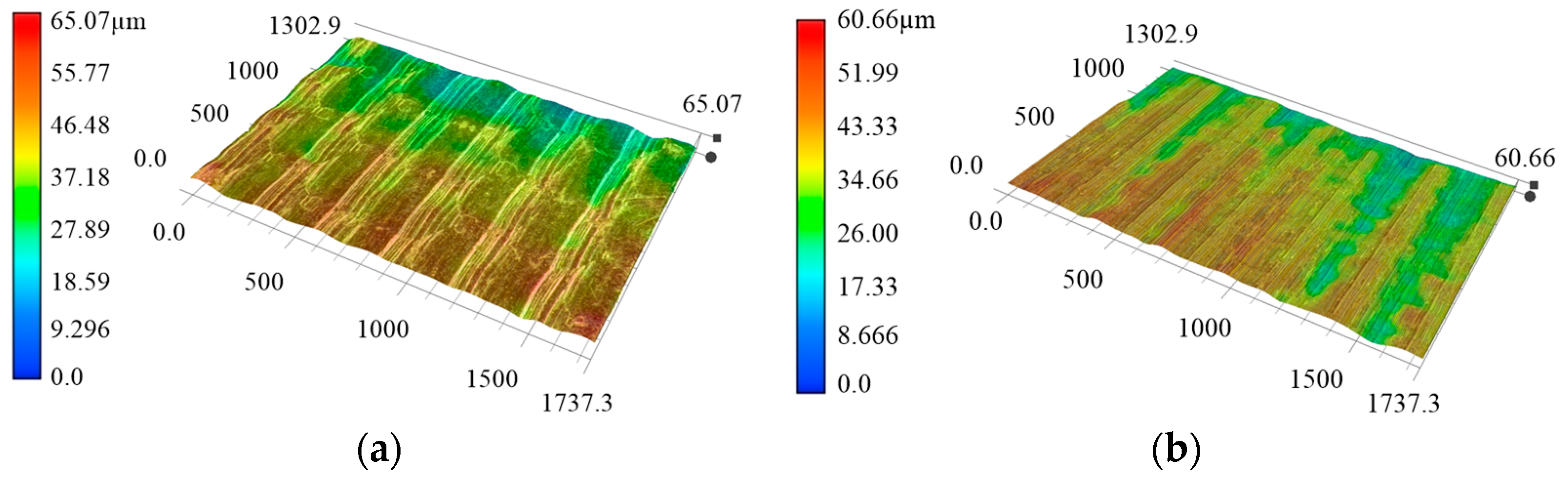
The surface topography of hardened steel with the carbide tool and PCBN tool under the same cutting parameters (Test 4) is shown in Figure 6. The surface texture of the workpiece machined by the PCBN tool was clear, and the ridge and the scallop of the surface texture caused by the feed rate were relatively low. Therefore, better surface topography could be obtained by machining hardened steel with the PCBN cutter.
The new PCBN tool and carbide tool were selected to cut the workpiece. The total cutting distance was 20,000 mm (the tool flank wear was less than 0.10 mm). Surface roughness was measured once every 2500 mm. Five different positions were selected for each measurement, and the average value of five surface roughness values was taken as the final result. The surface roughness values obtained at the same cutting distance are shown in Figure 7.
It was found that the surface quality of hardened steel machined by the cemented carbide tool was significantly higher than that machined by the PCBN tool. The surface roughness of hardened steel obtained by the carbide tool finishing was between 0.71 μm and 2.19 μm. The surface roughness of hardened steel obtained by the PCBN tool finishing was between 0.21 μm and 0.55 μm. The reasons for the difference in surface roughness were as follows: (1) the friction coefficient of the PCBN tool was relatively small; (2) the wear of the PCBN tool was relatively small with the processing.
3.3. Tool Life
The wear morphology and the wear rate of tool flank face at each cutting period were observed using a super-deep-scene 3D microscope. The wear curves of the PCBN tool and cemented carbide tool were obtained as shown in Figure 8.
When the cutting speed was 350 m/min and the cutting time was 60 min, the cemented carbide tool appeared damaged (as shown in Figure 8a). The reason was that the Co binder cannot withstand high temperature at high speed [27]. When the cutting speed was 150 m/min and 250 m/min, the cutting time before the cemented carbide tool reached the wear standard was significantly shorter than that of the PCBN tool. When the cutting speed was 50 m/min, the cutting performance of the cemented carbide tool was better than that of the PCBN tool. When the cutting speed was more than 150 m/min, the cutting performance of the PCBN tool was obviously higher than that of the cemented carbide tool. When the cutting speed was 50 m/min, the PCBN tool appeared damaged after 5 min of machining, as shown in Figure 8b.
Therefore, it was found that 150 m/min was the critical point for the PCBN tool and cemented carbide tool for intermittent machining of hardened steel. When the cutting speed was greater than 150 m/min, the performance of the PCBN tool was better than that of the cemented carbide tool; however, when the cutting speed was less than 150 m/min, the conclusion was just the opposite.
3.4. Chip Formation
The friction and thermal conductivity between the tool and the chip are different due to the different tool materials in the process of high-speed milling of hardened steel, which leads to a difference of the contact surface between the chip and the tool. Because the majority of the heat generated during cutting is carried away by the chips, the high-temperature chips would react with oxygen in the air and produce temper colors of the chips. Therefore, chip color can be a characteristic indicator of cutting temperature [28,29,30]. The color of the chips can reflect the cutting temperature. The deeper the chip color is, the higher the cutting temperature was [30]. The chip temperature of the PCBN tool and carbide tool for the intermittent machining of hardened steel is shown in Figure 9. The overall temperature of chips was higher during the intermittent machining of hardened steel with the cemented carbide tool, and the contact surface between the tool and chips was rough.
When the PCBN tool was used to machine hardened steel, the cutting temperature was higher at the smaller chip thickness. The reason was that the action mechanism between the cutter and the workpiece was mainly ploughing and extrusion in the place where the chip thickness was small. Because the size of chip section was small, the excessive heat generated by ploughing and extrusion could not be discharged in time and, thus, the chip color was deepened. When the cutting thickness was large, the cutting heat was mainly caused by the shear action and the friction between the cutter and the chip.
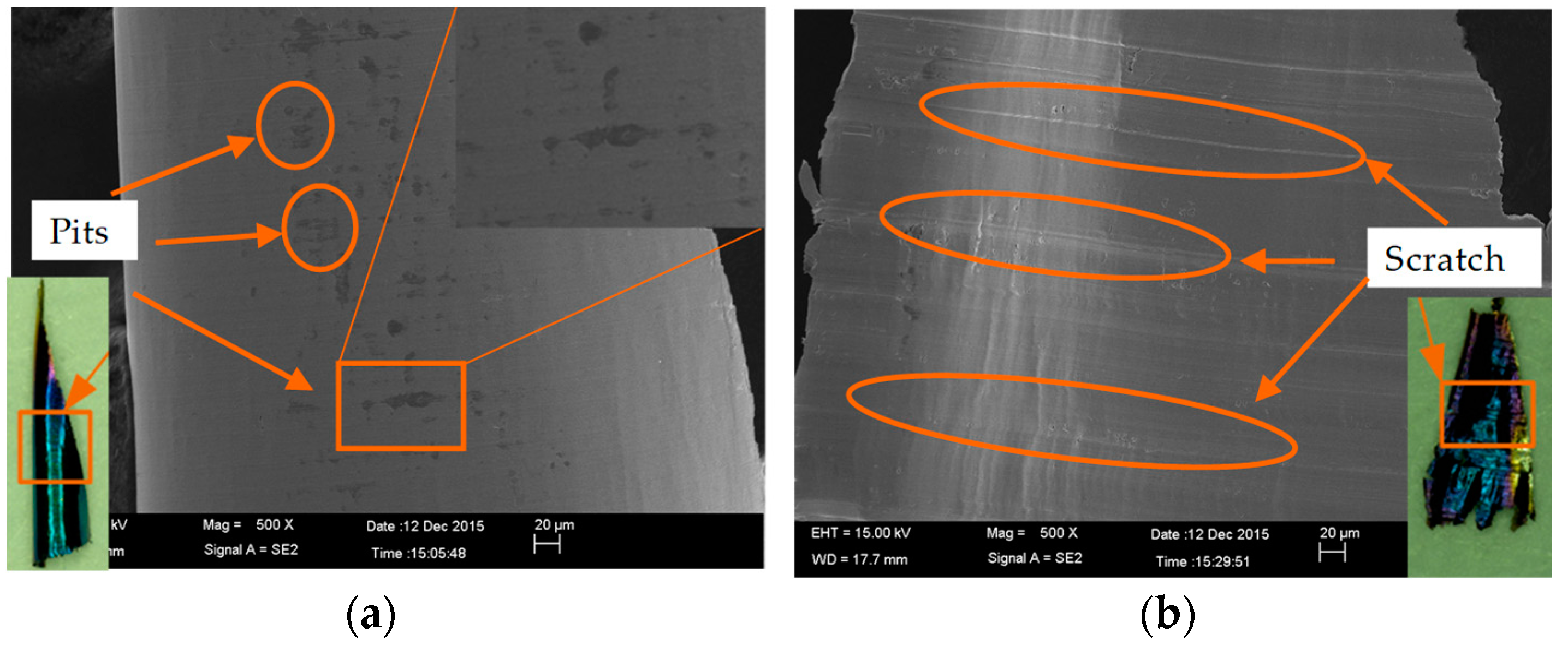
The microscopic characteristics of the chips of two tools under the same cutting conditions are shown in Figure 10. It was found that the chip contact surface of the PCBN cutter was smoother than that of the carbide cutter. The reason was that the PCBN tool had a smaller friction coefficient, which decreased the friction between the tool and chip. There were pits in the middle of the chip contact surface machined by the PCBN tool. The chip contact surface processed by the carbide cutter involved mainly parallel scratches.
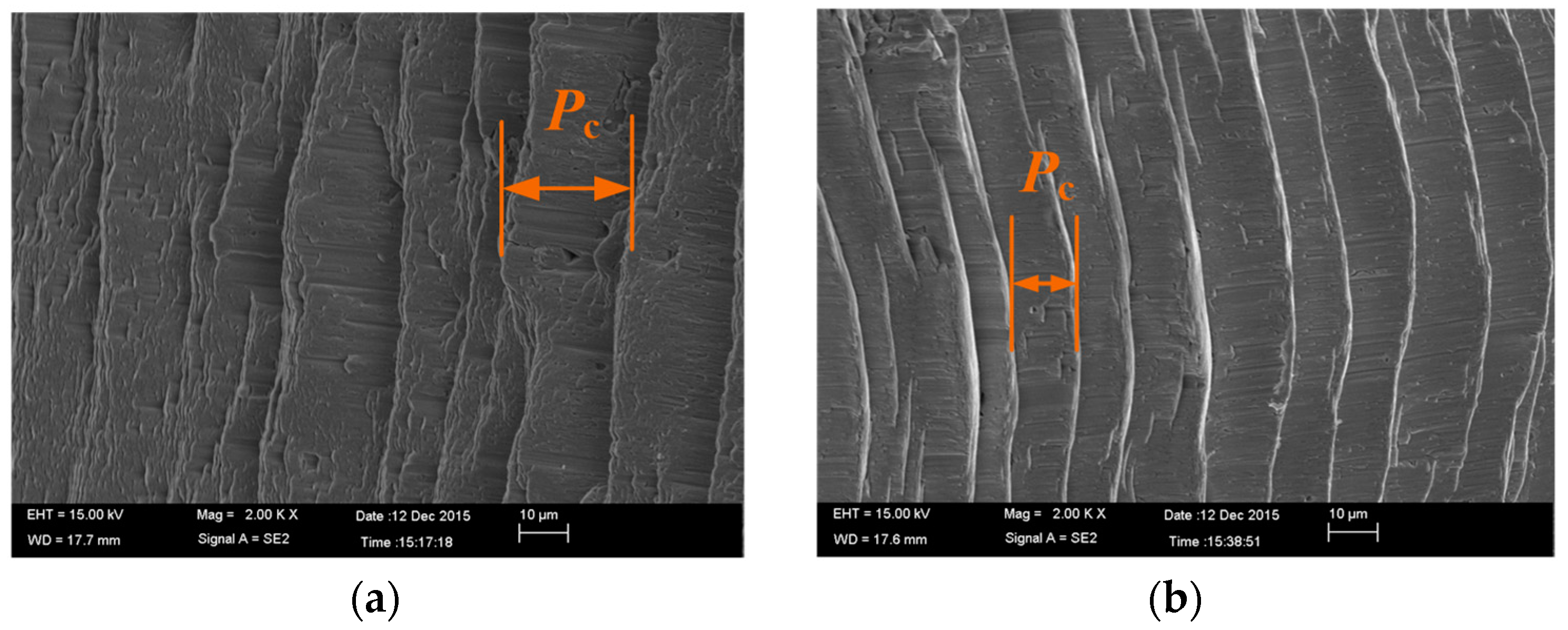
The free surface topologies of the chips processed by the two tools are shown in Figure 11. Pc represents the sawtooth pitch of chip. The sawtooth degree and the sawtooth pitch of chip machined by the PCBN tool were higher than those of the carbide cutting tool. The reason was that the larger flow velocity of the chip in the process using the PCBN cutting tool led to a stronger separation trend in the process of sawtooth chip formation, which further led to the increase of sawtooth pitch.
The free surface morphology of the chip processed by the PCBN cutter with different cutting speeds is shown in Figure 12. It was found that the sawtooth pitch of the chip (Pc) increased with the increase in cutting speed. The reason was that the increase in cutting speed made the shear slip more easily during chip formation, which led to the increase of sawtooth degree.
3.5. Flank Wear
(1) Oxidation Wear
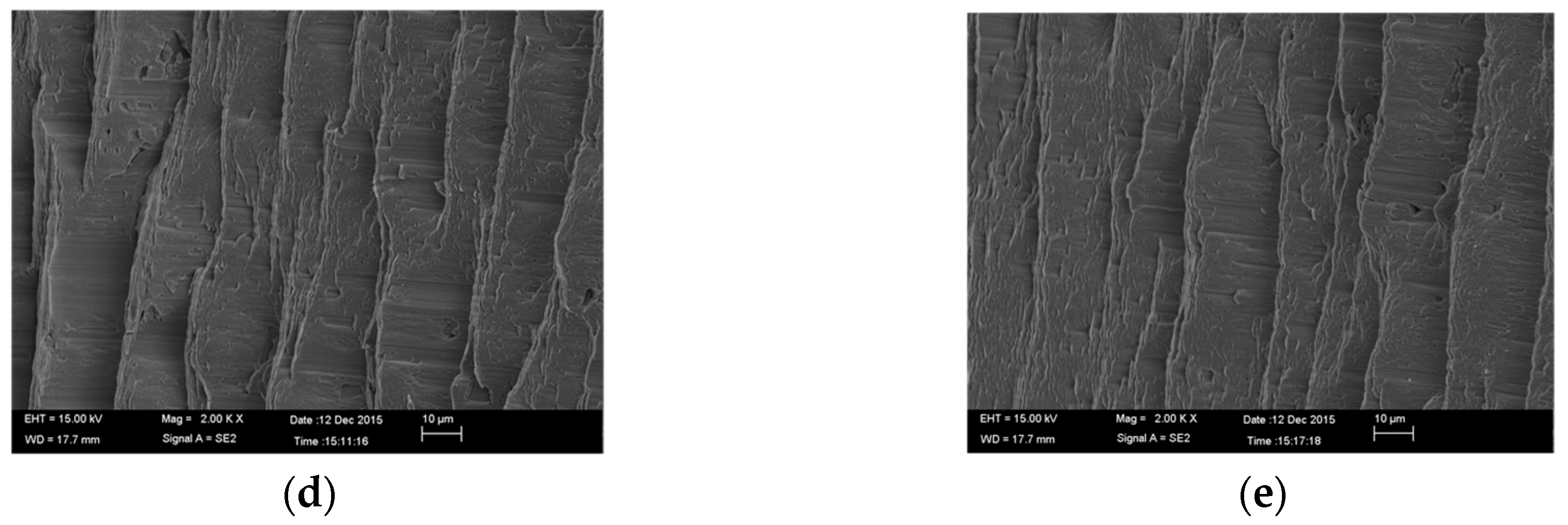
During the intermittent machining of hardened steel, at a certain temperature, some elements in the tool material reacted with O in the air, which accelerated the tool wear. The wear morphology and element analysis results of the PCBN tool flank are shown in Figure 13. Element analysis results for unworn area A and worn area B are shown in Figure 13c,d. Compared with the elemental analysis at A, the content of oxygen at B was significantly increased. It could be seen from Figure 13b that a concave shape was present for the CBN grains, resulting from possible oxidation of boron nitride into B2O3. Therefore, oxidation wear occurred during the intermittent machining of hardened steel.
(2) Diffusion Wear
During the cutting process, under certain conditions, certain elements may spread from one region to another, thereby causing diffusion wear. Diffusion wear can cause the chemical composition of the tool, thus weakening the tool cutting performance. Figure 14 shows the change law of element contents from the unworn area (A) to the worn area (B).
It could be seen from Figure 14b that the contents of iron and chromium were significantly increased, which indicated that iron and chromium diffused from the workpiece material to the cutting tool. Therefore, diffusion wear occurred during the intermittent machining of hardened steel.
(3) Adhesive Wear
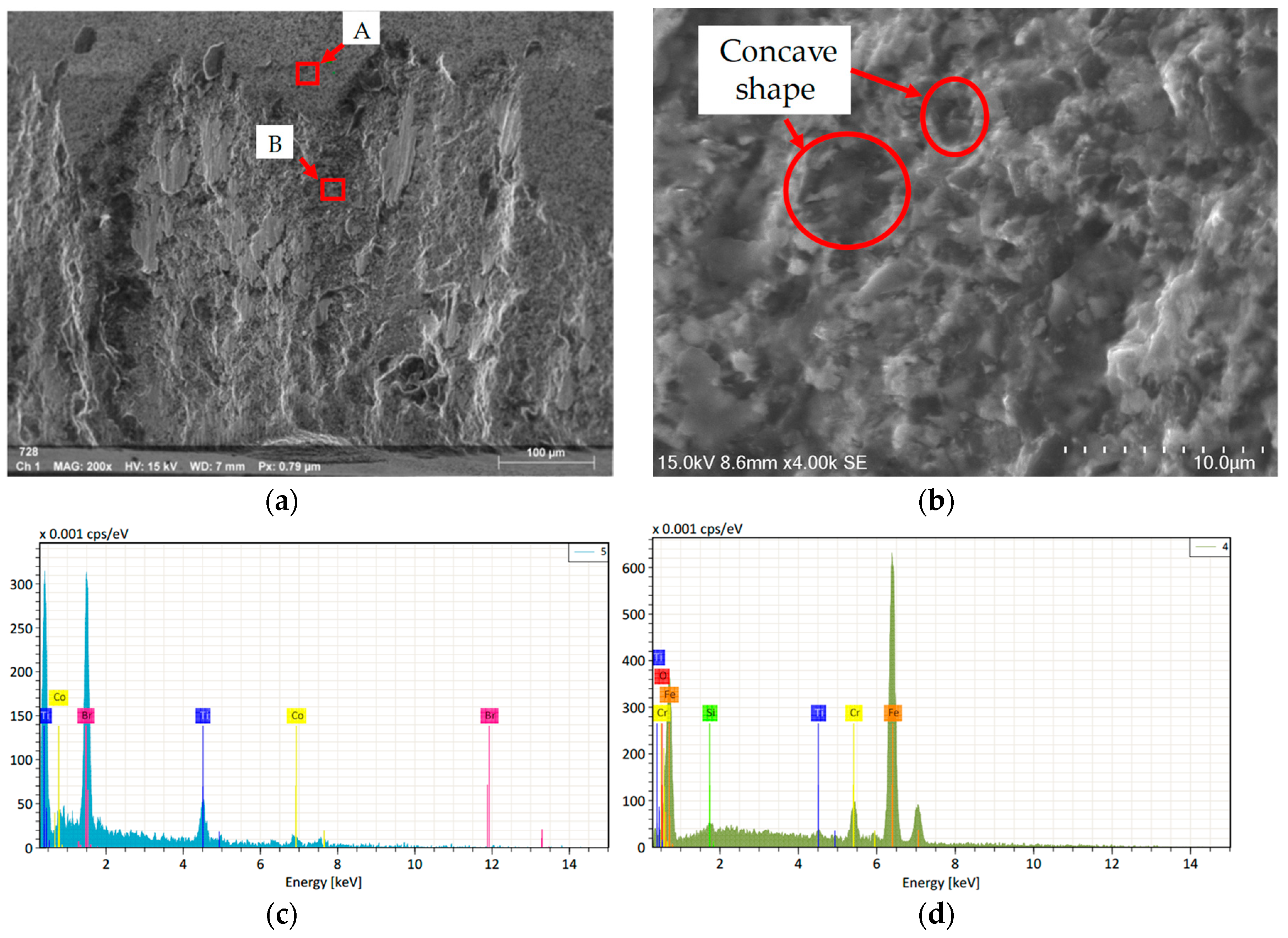
In the high-speed milling of hardened steel, due to the high temperature and pressure between the chip and the flank face, chips were observed to adhere to the cutting edge easily, and chip and tool welding clearly occurred, as shown in Figure 15a. Chips on the cutting edge were introduced into the processing region and rubbed or collided with the workpiece surface before eventually falling off. When chips fell off, adhesive wear of the tool occurred. Elemental analysis was performed at point A, and the results are shown in Figure 15b. It was found that iron and chromium were detected on the top and bottom surfaces of the chips. Therefore, the wear mechanism of the PCBN tool included adhesive wear.
In total, a combination of oxidation wear, adhesive wear, and diffusion wear was believed to control the flank wear of the PCBN cutting tool.
3.6. Tool Damage
There are three types of tool damage: the first type of damage is low-speed chipping; the second type of damage is crack-free fragmentation; the third type is high-speed damage [31]. Ten PCBN tools were used to study tool damage, five of which were used to study low-speed impact damage. The failure modes of PCBN tools at different cutting speeds are shown in Figure 16. The main failure modes of PCBN tools in the process of cutting hardened steel at low speed were tool micro-chipping, and low-rate impact damage of the rake face and the flank face. The main failure modes of PCBN tools in the process of cutting hardened steel at high speed were flank wear and high-rate fatigue damage.
In the low-speed machining process of hardened steel, the rake face of the PCBN tool suffered micro-chipping, as shown in Figure 16a. When the tool rake face suffered micro-chipping, the extrusion effect of the tool on the machined surface increased, which led to a sharp increase in cutting temperature. Then, the chips were melted and adhered to the tool tip (as shown in Figure 17), which further led to the deterioration of the cutting position of the tool tip.
There were two main forms of low-rate impact damage of PCBN tools in the intermittent machining of hardened steel: (1) the conchoidal damage of the rake face (as shown in Figure 16b); (2) the larger damaged area of the flank face (as shown in Figure 16c). The conchoidal damage of the rake face was mainly caused by the improper selection of feed and cutting depth at a small cutting speed. This form of damage was mainly caused by mechanical impact. The larger damaged area of the flank face was caused by the bending stress of the cutter, which was greater than the bending strength of the tool material itself [31].
The wear mechanism of the flank was detailed in Section 3.5.
PCBN tools can resist high-temperature wear at high speed. However, in intermittent machining, the tool was subjected to alternating thermal load and impact load, which led to fatigue crack of the tool after a certain period of stable cutting. The crack extension led to high-speed fatigue damage of the cutter, as shown in Figure 16e.
4. Conclusions and Outlook
The cutting performances (cutting force, chip, surface quality, tool life) and the wear/damage characteristics of PCBN tools were investigated for the intermittent machining of hardened steel (Cr12MoV, 59HRC). The main conclusions were as follows:
- Based on the evaluation indexes of cutting force, surface quality, chip morphology, and cutting temperature, it was concluded that the cutting performance of the PCBN tool was better than that of the coated cemented carbide tool.
- A combination of oxidation wear, adhesive wear, and diffusion wear was believed to control the flank wear of the PCBN cutting tool.
- The main failure modes of the PCBN tool in the machining of hardened steel at low speed were tool micro-chipping, and low-rate impact damage of the rake face and the flank face. The main failure modes of the PCBN tool in the machining of hardened steel at high speed were flank wear and high-rate fatigue damage.
- The PCBN tool’s life is affected by the cutting speed. When the cutting speed was greater than 150 m/min, the PCBN tool’s life was better than that of the carbide tool. Meanwhile, PCBN tools should be avoided at low cutting speeds.
- The sawtooth pitch of chip increased with the increase in cutting speed. The reason was that the increase in cutting speed made the shear slip more easily during chip formation, which led to the increase in sawtooth degree.
- When the PCBN tool was used to machine hardened steel, the cutting temperature was higher at the smaller chip thickness. The reason was that the action mechanism between the cutter and the workpiece was mainly ploughing and extrusion in the place where the chip thickness was small. Because the size of chip section was small, the excessive heat generated by ploughing and extrusion could not be discharged in time and, thus, the chip color was deepened.
Author Contributions
The idea of this project was conceived by H.G.; H.G. consulted to relevant high-level papers on aspect of cutting performance and wear/damage characteristics of PCBN tool in hard milling, and wrote this project; X.L. and Z.C. reviewed this project and proposed constructive guidance to make the article more complete.
Funding
This project was supported by the Projects of International Cooperation and Exchanges NSFC (51720105009).
Conflicts of Interest
The authors declare no conflict of interest.
References
- Huang, Y.; Chou, Y.K.; Liang, S.Y. CBN tool wear in hard turning: a survey on research progresses. Int. J. Adv. Manuf. Technol. 2007, 35, 443–453. [Google Scholar] [CrossRef]
- Monteiro, S.N.; Skury, A.L.; de Azevedo, M.G.; Bobrovnitchii, G.S. Cubic boron nitride competing with diamond as a superhard engineering material—An overview. J. Mater. Res. Technol. 2013, 2, 68–74. [Google Scholar] [CrossRef]
- Xi, Y.; Zhan, H.; Rashid, R.R.; Wang, G.; Sun, S.; Dargusch, M. Numerical modeling of laser assisted machining of a beta titanium alloy. Comp. Mater. Sci. 2014, 92, 149–156. [Google Scholar] [CrossRef]
- Taylan, F.; Çolak, O.; Kayacan, M.C. Investigation of TiN coated CBN and CBN cutting tool performance in hard milling application. Strojniski Vestnik J. Mech. Eng. 2011, 57, 417–424. [Google Scholar] [CrossRef]
- Kurt, A.; Şeker, U. The effect of chamfer angle of polycrystalline cubic boron nitride cutting tool on the cutting forces and the tool stresses in finishing hard turning of AISI 52100 steel. Mater. Des. 2005, 26, 351–356. [Google Scholar] [CrossRef]
- Li, S.; Chen, T.; Qiu, C.; Wang, D.; Liu, X. Experimental investigation of high-speed hard turning by PCBN tooling with strengthened edge. Int. J. Adv. Manuf. Technol. 2017, 92, 3785–3793. [Google Scholar] [CrossRef]
- Zhou, J.M.; Walter, H.; Andersson, M.; Stahl, J.E. Effect of chamfer angle on wear of PCBN cutting tool. Int. J. Mach. Tools Manuf. 2003, 43, 301–305. [Google Scholar] [CrossRef]
- Özel, T.; Karpat, Y.; Srivastava, A. Hard turning with variable micro-geometry PcBN tools. CIRP Ann. Manuf. Technol. 2008, 57, 73–76. [Google Scholar] [CrossRef] [Green Version]
- Poulachon, G.; Bandyopadhyay, B.P.; Jawahir, I.S.; Pheulpin, S.; Seguin, E. The influence of the microstructure of hardened tool steel workpiece on the wear of PCBN cutting tools. Int. J. Mach. Tools Manuf. 2003, 43, 139–144. [Google Scholar] [CrossRef]
- Khanna, N.; Rashid RA, R.; Palanisamy, S. Experimental evaluation of the effect of workpiece heat treatments and cutting parameters on the machinability of Ti-10V-2Fe-3Al β titanium alloy using Taguchi’s design of experiments. Int. J. Mach. Mach. Mater. 2017, 19, 374–393. [Google Scholar]
- Zareena, A.R.; Rahman, M.; Wong, Y.S. Binderless CBN tools, a breakthrough for machining titanium alloys. J. Manuf. Sci. Eng. 2005, 127, 277–279. [Google Scholar] [CrossRef]
- Li, L.; Wu, M.; Liu, X.; Cheng, Y.; Yu, Y. Experimental study of the wear behavior of PCBN inserts during cutting of GH4169 superalloys under high-pressure cooling. Int. J. Adv. Manuf. Technol. 2018, 95, 1941–1951. [Google Scholar] [CrossRef]
- Pavel, R.; Marinescu, I.; Deis, M.; Pillar, J. Effect of tool wear on surface finish for a case of continuous and interrupted hard turning. J. Mater. Process. Technol. 2005, 170, 341–349. [Google Scholar] [CrossRef]
- Ko, T.J.; Kim, H.S. Surface integrity and machineability in intermittent hard turning. Int. J. Adv. Manuf. Technol. 2001, 18, 168–175. [Google Scholar] [CrossRef]
- Oliveira, A.J.; Diniz, A.E.; Ursolino, D.J. Hard turning in continuous and interrupted cut with PCBN and whisker-reinforced cutting tools. J. Mater. Process. Technol. 2009, 209, 5262–5270. [Google Scholar] [CrossRef]
- Tang, L.; Sun, Y.; Li, B.; Shen, J.; Meng, G. Wear performance and mechanisms of PCBN tool in dry hard turning of AISI D2 hardened steel. Tribol. Int. 2018, 132, 228–236. [Google Scholar] [CrossRef]
- Chen, L.; Stahl, J.E.; Zhao, W.; Zhou, J. Assessment on abrasiveness of high chromium cast iron material on the wear performance of PCBN cutting tools in dry machining. J. Mater. Process. Technol. 2018, 255, 110–120. [Google Scholar] [CrossRef]
- Gutnichenko, O.; Bushlya, V.; Zhou, J.; Ståhl, J.E. Tool wear and machining dynamics when turning high chromium white cast iron with pcBN tools. Wear 2017, 390, 253–269. [Google Scholar] [CrossRef]
- Gopalsamy, B.M.; Mondal, B.; Ghosh, S.; Arntz, K.; Klocke, F. Experimental investigations while hard machining of DIEVAR tool steel (50 HRC). Int. J. Adv. Manuf. Technol. 2010, 51, 853–869. [Google Scholar] [CrossRef]
- Wojciechowski, S.; Twardowski, P. Tool Life and Process Dynamics in High Speed Ball End Milling of Hardened Steel. Procedia CIRP 2012, 1, 289–294. [Google Scholar] [CrossRef] [Green Version]
- Okada, M.; Hosokawa, A.; Tanaka, R.; Ueda, T. Cutting performance of PVD-coated carbide and CBN tools in hardmilling. Int. J. Mach. Tools Manuf. 2011, 51, 127–132. [Google Scholar] [CrossRef]
- Elbestawi, M.A.; Chen, L.; Becze, C.E.; El-Wardany, T.I. High-Speed Milling of Dies and Molds in Their Hardened State. CIRP Ann. Manuf. Technol. 1997, 46, 57–62. [Google Scholar] [CrossRef]
- Boing, D.; Schroeter, R.B.; de Oliveira, A.J. Three-dimensional wear parameters and wear mechanisms in turning hardened steels with PCBN tools. Wear 2018, 398, 69–78. [Google Scholar] [CrossRef]
- Luo, S.Y.; Liao, Y.S.; Tsai, Y.Y. Wear characteristics in turning high hardness alloy steel by ceramic and CBN tools. J. Mater. Process. Technol. 1999, 88, 114–121. [Google Scholar] [CrossRef]
- Saketi, S.; Sveen, S.; Gunnarsson, S.; M’Saoubi, R.; Olsson, M. Wear of a high cBN content PCBN cutting tool during hard milling of powder metallurgy cold work tool steels. Wear 2015, 332, 752–761. [Google Scholar] [CrossRef]
- Cui, X.; Guo, J.; Zhao, J.; Yan, Y. Analysis of PCBN tool failure mechanisms in face milling of hardened steel using damage equivalent stress. Int. J. Adv. Manuf. Technol. 2015, 80, 1985–1994. [Google Scholar] [CrossRef]
- Rashid, R.R.; Palanisamy, S.; Sun, S.; Dargusch, M. A case-study on the mechanism of flank wear during laser-assisted machining of a titanium alloy. Int. J. Mach. Mach. Mater. 2017, 19, 538–553. [Google Scholar] [CrossRef]
- Venkatesh, V.C.; Zhou, D.Q.; Xue, W.; Quinto, D.T. A study of chip surface characteristics during the machining of steel. CIRP Ann. 1993, 42, 631–636. [Google Scholar] [CrossRef]
- Ning, Y.; Rahman, M.; Wong, Y.S. Investigation of chip formation in high speed end milling. J. Mater. Process. Technol. 2001, 113, 360–367. [Google Scholar] [CrossRef]
- Zhang, S.; Guo, Y.B. An experimental and analytical analysis on chip morphology, phase transformation, oxidation, and their relationships in finish hard milling. Int. J. Mach. Tool. Manuf. 2009, 49, 805–813. [Google Scholar] [CrossRef]
- Xing, G. Metal Cutting Technology; China Agriculture Press: Beijing, China, 1983; pp. 6–7. [Google Scholar]
Figure 1.
Cutting tools for experiments: (a) carbide cutting tool; (b) PCBN tool.

Figure 2.
Experimental site.

Figure 3.
The effect of milling speed on milling forces: (a) Fx; (b) Fy; (c) Fz.


Figure 4.
The effect of milling speed on milling forces: (a) Fx; (b) Fy; (c) Fz.

Figure 5.
The effect of milling speed on milling forces: (a) Fx; (b) Fy; (c) Fz.

Figure 6.
The machined surface topography (Test 4): (a) carbide cutting tool; (b) PCBN tool.

Figure 7.
The machined surface roughness (Test 4): (a) PCBN tool; (b) carbide cutting tool.

Figure 8.
Tool wear curve (Test 1): (a) carbide cutting tool; (b) PCBN tool.

Figure 9.
Chip temperature distribution (Test 5): (a) PCBN tool; (b) carbide cutting tool.

Figure 10.
Chip contact surface topography (Test 5): (a) PCBN tool; (b) carbide cutting tool.

Figure 11.
Chip free surface topography (Test 6, v = 500 m/min): (a) PCBN tool; (b) carbide cutting tool.
Figure 11.
Chip free surface topography (Test 6, v = 500 m/min): (a) PCBN tool; (b) carbide cutting tool.

Figure 12.
Chip free surface topography machined by the PCBN tool with different cutting speeds (Test 6): (a) v = 250 m/min, Pc = 69 μm; (b) v = 314 m/min, Pc = 76 μm; (c) v = 376 m/min, Pc = 85 μm; (d) v = 440 m/min, Pc = 92 μm; (e) v = 500 m/min, Pc = 98 μm.
Figure 12.
Chip free surface topography machined by the PCBN tool with different cutting speeds (Test 6): (a) v = 250 m/min, Pc = 69 μm; (b) v = 314 m/min, Pc = 76 μm; (c) v = 376 m/min, Pc = 85 μm; (d) v = 440 m/min, Pc = 92 μm; (e) v = 500 m/min, Pc = 98 μm.


Figure 13.
Oxidation wear (Test 1 250 m/min): (a) wear surface morphology of flank face; (b) local amplification at point B; (c) elemental analysis at point A; (d) elemental analysis at point B.
Figure 13.
Oxidation wear (Test 1 250 m/min): (a) wear surface morphology of flank face; (b) local amplification at point B; (c) elemental analysis at point A; (d) elemental analysis at point B.

Figure 14.
Diffusion wear (Test 1 250 m/min): (a) the range of elemental analysis; (b) the change law of element contents.
Figure 14.
Diffusion wear (Test 1 250 m/min): (a) the range of elemental analysis; (b) the change law of element contents.

Figure 15.
Adhesive wear: (a) wear surface morphology of flank face; (b) elemental analysis at point A.
Figure 15.
Adhesive wear: (a) wear surface morphology of flank face; (b) elemental analysis at point A.

Figure 16.
Macroscopic damage morphology of PCBN tool intermittent cutting of hardened steel tool (Test 1): (a) micro-chipping (v = 50 m/min); (b) the rake face (v = 50 m/min); (c) the flank face (v = 50 m/min); (d) flank wear (v = 250 m/min); (e) high-rate fatigue damage (v = 350 m/min).
Figure 16.
Macroscopic damage morphology of PCBN tool intermittent cutting of hardened steel tool (Test 1): (a) micro-chipping (v = 50 m/min); (b) the rake face (v = 50 m/min); (c) the flank face (v = 50 m/min); (d) flank wear (v = 250 m/min); (e) high-rate fatigue damage (v = 350 m/min).

Figure 17.
The macrostructure of the tool rake face.


Table 1.
The chemical composition of the workpiece.
| Element | C | Cr | Mo | Si | Mn | Ni | V |
|---|---|---|---|---|---|---|---|
| % | 1.55 | 10.50 | 0.40 | ≤0.4 | ≤0.4 | 0 | 0.25 |
Table 2.
Physical properties of the workpiece.
| Density (g/cm3) | Thermal Conductivity (W/(m∙K)) | Specific Heat (J/(g∙K)) | Line Expansion Coefficient (K−1) | Elasticity Modulus (GPa) |
|---|---|---|---|---|
| 7.70 | 20.0 | 0.46 | 1.12 × 10⁻⁵ | 223 |
Table 3.
Physical properties of the coating film materials.
| Coating Film | Hardness (HV) | Surface Roughness Rz (μm) | Film Thickness (μm) | Thermal Effusivity J/(s0.5 m2 K) | Oxidizing Temperature (°C) |
|---|---|---|---|---|---|
| TiAlN | 4353 | 0.71 | 2.9 | 3027 | 800 |
Table 4.
Physical properties of base materials.
| Base Materials | Rockwell Hardness (HRA) | Young’s Modulus × 104 (kg/mm2) | Thermal Conductivity k (W/m∙K) at 20/500/900 °C | Thermal Diffusivity a × 106 (m2/s) at 20/500/900 °C |
|---|---|---|---|---|
| K10 | 91.1 | 6.4 | 91.7/74.4/68.1 | 31.9/18.9/15.0 |
Table 5.
Machining parameters.
| Test | Cutting Speed (m/min) | Feed per Tooth (mm/tooth) | Axial Depth of Cut (mm) | Radial Depth of Cut (mm) |
|---|---|---|---|---|
| 1 | 50, 150, 250, 350 | 0.05 | 0.05 | 0.3 |
| 2 | 250 | 0.1, 0.15, 0.2, 0.25 | 0.05 | 0.3 |
| 3 | 250 | 0.05 | 0.1, 0.15, 0.20, 0.25 | 0.3 |
| 4 | 300 | 0.15 | 0.3 | 0.3 |
| 5 | 376 | 0.1 | 0.3 | 0.3 |
| 6 | 250, 314, 376, 440, 500 | 0.25 | 0.3 | 0.3 |
© 2019 by the authors. Licensee MDPI, Basel, Switzerland. This article is an open access article distributed under the terms and conditions of the Creative Commons Attribution (CC BY) license (http://creativecommons.org/licenses/by/4.0/).
Share and Cite
MDPI and ACS Style
Gao, H.; Liu, X.; Chen, Z. Cutting Performance and Wear/Damage Characteristics of PCBN Tool in Hard Milling. Appl. Sci. 2019, 9, 772. https://doi.org/10.3390/app9040772
AMA Style
Gao H, Liu X, Chen Z. Cutting Performance and Wear/Damage Characteristics of PCBN Tool in Hard Milling. Applied Sciences. 2019; 9(4):772. https://doi.org/10.3390/app9040772
Chicago/Turabian StyleGao, Haining, Xianli Liu, and Zhitao Chen. 2019. "Cutting Performance and Wear/Damage Characteristics of PCBN Tool in Hard Milling" Applied Sciences 9, no. 4: 772. https://doi.org/10.3390/app9040772
Note that from the first issue of 2016, this journal uses article numbers instead of page numbers. See further details here.