Article

Numerical Investigation on Co-firing Characteristics of Semi-Coke and Lean Coal in a 600 MW Supercritical Wall-Fired Boiler

State Key Laboratory of Multiphase Flow in Power Engineering, School of Energy and Power Engineering, Xi’an Jiaotong University, Xi’an 710049, China
*
Author to whom correspondence should be addressed.
Appl. Sci. 2019, 9(5), 889; https://doi.org/10.3390/app9050889
Submission received: 23 January 2019 / Revised: 16 February 2019 / Accepted: 25 February 2019 / Published: 1 March 2019
(This article belongs to the Special Issue Clean Coal Combustion)

Abstract

:
Semi-coke is one of the principal by-products of coal pyrolysis and gasification, which features the disadvantages of ignition difficulty, low burnout rate, and high nitrogen oxides (NOx) emission during combustion process. Co-firing semi-coke with coal is a potential approach to achieve clean and efficient utilization of such low-volatile fuel. In this paper, the co-firing performance of semi-coke and lean coal in a 600 MW supercritical wall-fired boiler was numerically investigated which has been seldom done previously. The influences of semi-coke blending ratio, injection position of semi-coke, excess air ratio in the main combustion zone, the co-firing method, and over fire air (OFA) arrangement on the combustion efficiency and NOx generation characteristics of the utility boiler were extensively analyzed. The simulation results indicated that as the blending ratio of semi-coke increased, the NOx emission at furnace outlet decreased. The blending methods (in-furnace versus out-furnace) had certain impacts on the NOx emission and carbon content in fly ash, while the in-furnace blending method showed more flexibility in co-firing adjustment. The injection of semi-coke from the upper burners could significantly abate NOx emission at the furnace outlet, but also brought about the rise of carbon content in fly ash and the increase of outlet temperature. Compared with the condition that semi-coke and lean coal were injected from different burners, the burnout ratio of the blend premixed outside the furnace was higher at the same blending ratio of semi-coke. With the excess air ratio in the main combustion zone increased, NOx concentration at the furnace outlet was increased. The excess air ratio of 0.75 in the main combustion zone was recommended for co-firing 45% semi-coke with lean coal. The operational performance of the boiler co-firing semi-coke was greatly affected by the arrangement of OFA as well. The amount of NOx generated from the supercritical wall-fired boiler could be reduced with an increase of the OFA height.

1. Introduction

Nowadays, coal plays a crucial role in energy resources worldwide, especially in China, and will still hold an important position in future. At present, the proven reserves of coal resources in China are as high as 140 billion tons, of which low-rank coal accounts for about 50% [1,2,3,4,5]. Due to the fact that the content of moisture in low-rank coal is high, the efficiency of direct combustion for power generation is relatively low. The grading conversion utilization of low-rank coal can improve this situation. Semi-coke is the solid by-product that low-rank coal pyrolyzes under low temperature [6,7,8], which has the characteristics of low volatile content and high heat value. Large particles of pyrolysis semi-coke can be used in chemical applications; however, small particles and powdered pyrolysis semi-coke are difficult to utilize in traditional chemical industry. With the booming coal industry in China, the coal grading conversion increases and the production of semi-coke is promoted accordingly. A large amount of semi-coke is urgently needed to be burned and utilized. Hence, the use of semi-coke as a power fuel in the field of power generation is a feasible solution. The combustion instability, poor ignition, low burnout ratio, and high NOx emission are common problems during the combustion of semi-coke, inducing the difficulty to achieve efficient and clean utilization [8,9,10,11,12,13,14]. In previous studies, the circulating fluidized bed (CFB) boilers were mainly used to explore the combustion of semi-coke [1,15,16]. However, the vast majority of boilers in operation in China are pulverized coal fired boilers. Consequently, except for CFB boilers, the pulverized-coal fired boilers are also another preferable option for the combustion of semi-coke in large-scale. However, the direct combustion of semi-coke in existing power plants is usually greatly difficult. Therefore, it is a feasible strategy to co-fire semi-coke and coal.
With the shortage of high-quality coal resources and enhancement of environmental awareness, extensive research has been conducted focusing on the NOx generation and combustion characteristics of co-firing solid fuels [17,18,19]. Lee et al. [20,21] studied that the influence of two blending methods on NOx emission and burnout characteristics of blended coals (bituminous coal and sub-bituminous coal) in the co-firing process using both experimental and simulation approaches. The results showed that the combustion characteristics of the in-furnace units were better than those of the out-furnace case. Ikeda et al. [22] investigated that the NOx emission and burnout ratio of co-firing the bituminous coal and lignite, and indicated that the concentration of NOx increased with the moisture content in lignite. Li et al. [23] explored the influences of excess air ratio and side over fire air (SOFA) arrangement on the temperature distribution, NOx emissions and burnout characteristics of blended coal. They revealed that the fuel type exhibited certain influence on the temperature distributions and NOx emissions during the co-combustion process. Most of the previous studies involved the co-firing behaviors of bituminous coal and other kinds of coals, which are difficult to guide in pulverized-coal fired boilers. The exploration of co-firing bituminous coal and semi-coke was firstly conducted in a 300 MW tangentially-fired boiler in our previous study [24]. The study suggested that semi-coke can be co-fired with coal in utility boilers. However, to our knowledge, no study has been conducted on the blends of semi-coke and lean coal in supercritical or ultra-supercritical wall-fired utility boilers. The influences of blending ratio and blending method of semi-coke on combustion performance and NOx emission on such wall-fired boilers are still unclear. More efforts remain necessary to optimize the air distribution during the co-firing process to improve the combustion performance of blends. More research should be performed to find the optimal operation mode of co-firing lean coal and semi-coke in wall-fired boilers.
Because of the high cost of obtaining relevant data through in-situ tests, the retrofitting and optimizations of utility boilers using solid fuels can be guided by the numerical approach. In this paper, the combustion and NOx generation characteristics of co-firing lean coal and semi-coke in a 600 MW supercritical wall-fired boiler were numerically studied. After the model validation according to some data from in-situ tests, the influences of semi-coke blending ratio, injection strategies of semi-coke, blending method, excess air ratio in primary combustion zone, and over fire air (OFA) arrangement on the NOx generation and boiler operation performance of co-firing lean coal and semi-coke were investigated and some strategies for the operation optimization were further discussed. The present study can provide guidance for practical application of blending semi-coke in wall-fired boilers and promote clean and efficient usage of semi-coke, which is of benefit for coal grading utilization.

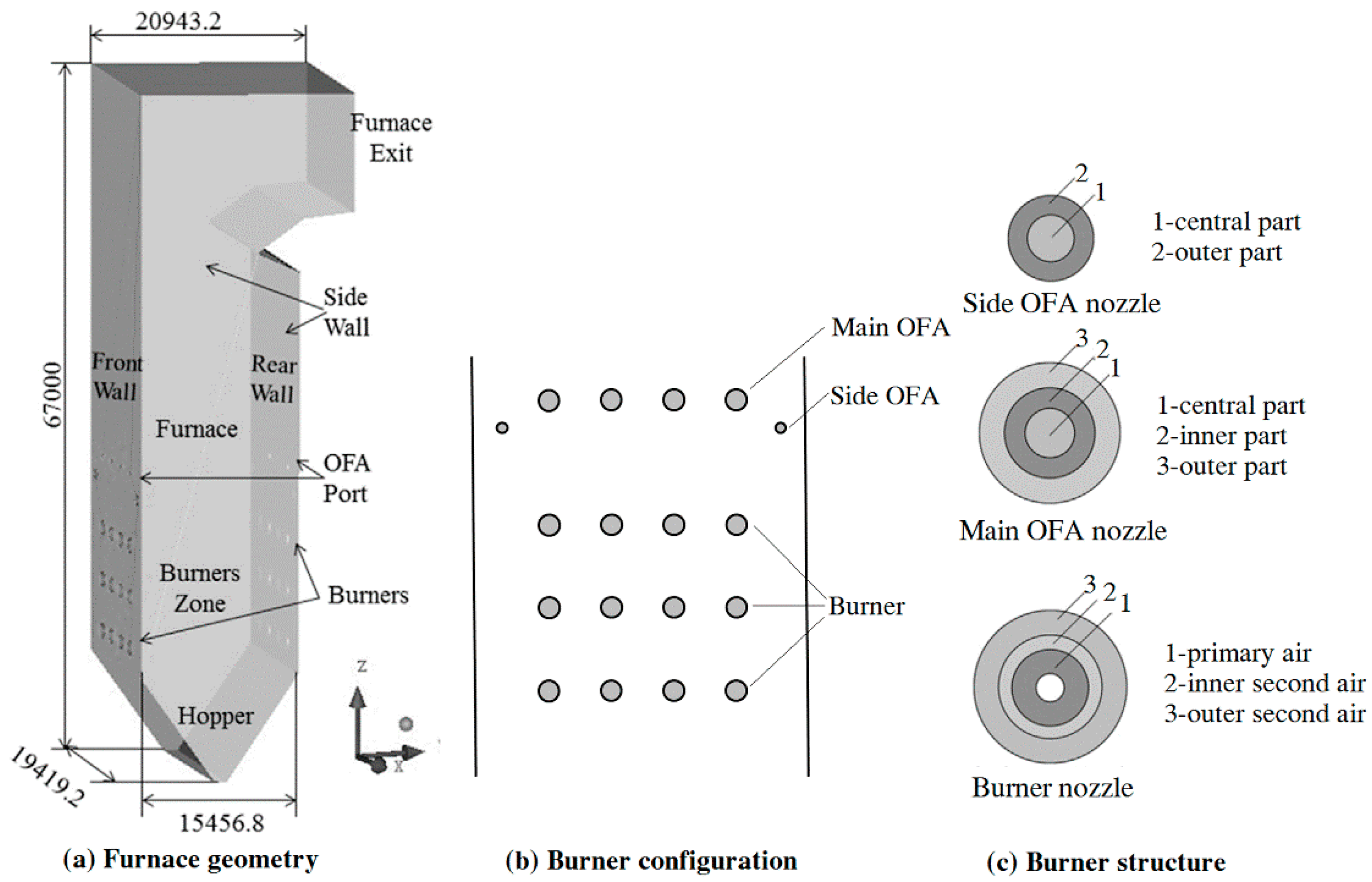
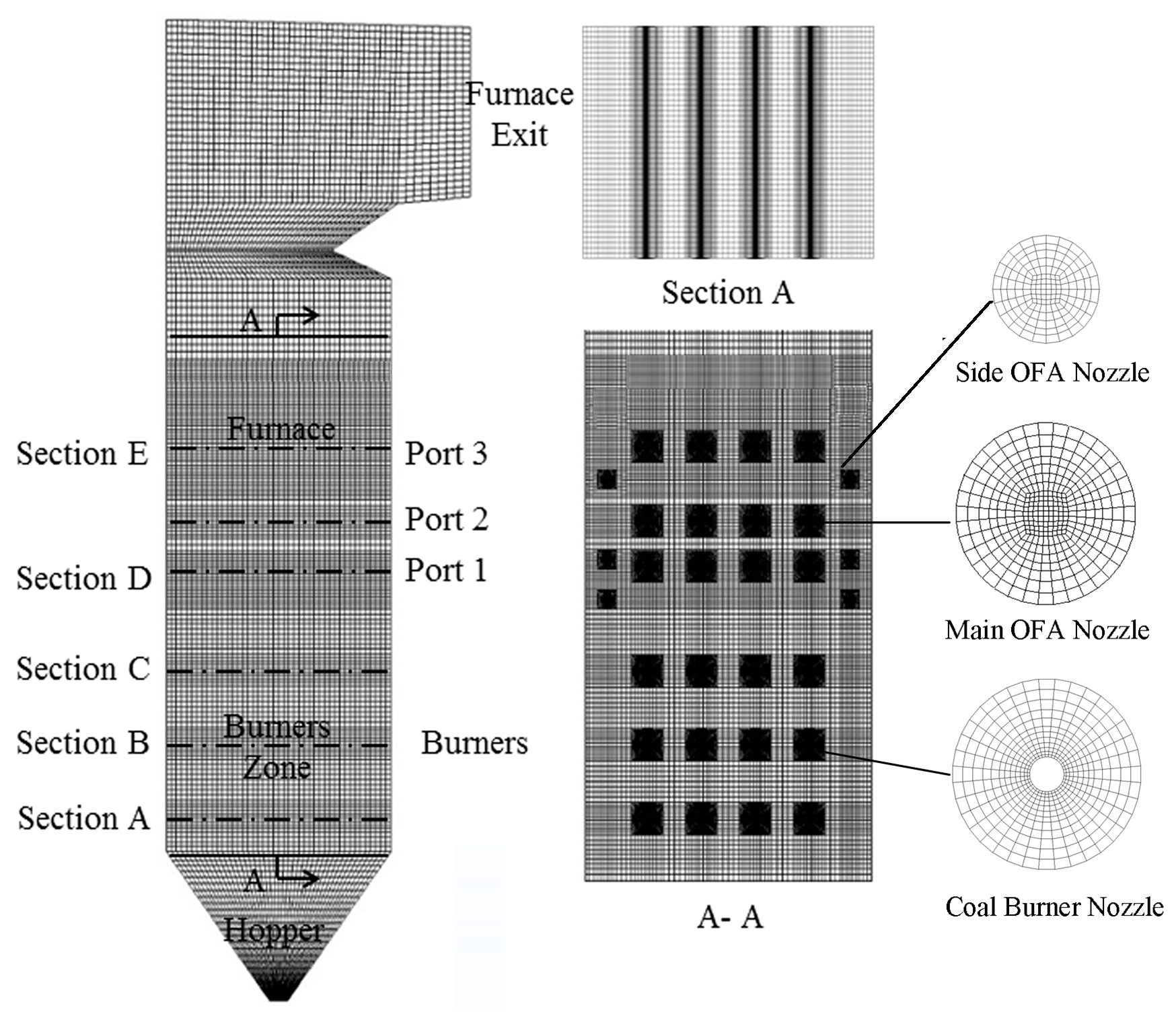
2. Boiler Configuration

The 600 MW opposed wall-fired boiler in this study is a supercritical once-through one with variable pressure operation. The height, width, and depth of the boiler are respectively 67 m, 19.4 m, and 15.4 m. Figure 1 shows the boiler geometry, burner configuration, and structure. The boiler adopts hierarchical combustion technology and opposed wall-fired combustion system. The front and rear walls of the furnace are symmetrically arranged with three layers of swirl burners and each layer has eight swirl burners. The primary wind was distributed in the middle of the channel. Meanwhile, a layer of OFA nozzles is arranged above the primary area and each layer includes four SOFA nozzles and eight main over fire air (MOFA) nozzles. The MOFA nozzle has one more part than the SOFA nozzle. In our previous work, more detailed information about this boiler can be found [25,26,27].

3. Modeling Methodology

3.1. Mesh Generation

The Integrated Computer Engineering (ICEM) was used to divide the boiler model into the mesh system. Considering the influence of OFA arrangement on co-firing lean coal and semi-coke, two more layers of OFA nozzles were arranged above the OFA layer in practical boiler. When the boiler was divided to structured hexahedral grids, the primary combustion zone grids were refined. The mesh system of the wall-fired boiler employed in the present work is described in Figure 2. If the mesh is relatively sparse, calculation results may be inaccurate. If the mesh is too dense, the computing time can be excessively prolonged. When the change of calculated results is defined within the allowable deviation range of the practical application by continuing to refine grids, the number of grids can be determined. Three sets of mesh system with the grid number of 1102158, 1796184 and 2402552 were used to verify the grid independence here. The comparative results of the average temperature along the height of the furnace with three different grid numbers are described in Figure 3. The temperature variations along the furnace height obtained by 1796184 and 2402552 cells were almost the same. Hence, it can be considered the mesh system of 1796184 cells met the condition of grid independence. Based on both calculation accuracy and simulation efficiency, the mesh system included 1796184 cells [25,26,28].

3.2. Decription of Numerical Models

The software Fluent 14.5 was utilized to simulate the results in the present study. The combustion of pulverized coal mainly includes thermal decomposition, volatile gas phase combustion, char combustion, and other physical and chemical processes, which is very complex. Due to many factors involved, more reliable simulation results can be obtained by selecting numerical sub-models in Fluent. In the present study, the standard k-ε model was applied to calculate the turbulent flow in view of accuracy and stability. The interaction between particles and gases in radiation was included, and Lagrange method was adopted to track and calculate the particle movement. The kinetics/diffusion-limited model was used to described the combustion of char, and the devolatilization ratio of pulverized coal was described by the two-competing-reactions model [29,30]. The calculation of radiant heat transfer adopted the P-1 model, where the number of bands was selected to be zero. In other words, the radiation in furnace was approximately pure gray. The gas-phase turbulence-chemistry interaction was depicted by the finite-rate/eddy-dissipation model, and the reaction of gas phase is included the following four equations [26,31]:
C H y O x + ( 0.5 + 0.25 y 0.5 x ) O 2 C O + 0.5 y H 2 O
C O + 0.5 O 2 C O 2
C O + H 2 O C O 2 + H 2
H 2 + 0.5 O 2 H 2 O
It is generally believed that the main combustion process and the flow field are slightly affected by the NOx concentration in numerical simulations. Therefore, the calculation of NOx adopted a post-processing method based on the stable temperature field and flow field. This method greatly simplified the calculation work and could satisfy the precision requirement in practical applications [24]. According to the source and generation path of nitrogen, NOx can be divided into three types: prompt NOx, fuel NOx, and thermal NOx. Among them, the production of prompt NOx in pulverized boilers is usually negligible [32,33]. In the present calculation process, thermal NOx and fuel NOx were considered. The reaction of nitrogen and oxygen in the air mainly produced Thermal NOx, and the formation of thermal NOx was explained by the mechanism of Zeldovich [24]. Fuel NOx is produced by nitrogen oxidation in fuels and the formation of fuel NOx originates from the oxidation of nitrogen in volatile and char. It was believed that the reaction process of nitrogen in coal was that fuel-N was first mainly converted to HCN and NH3, and then NH3 and HCN were reduced to N2 or oxidized to NO through competitive reactions.

3.3. Cases Conditions

The combustion and NOx production characteristics under various semi-coke blending ratios, injection positions of semi-coke, blending method, excess air ratios in primary combustion zone, and OFA arrangements in a 600 MW supercritical wall-fired boiler were further studied. In this paper, lean coal and semi-coke are selected in simulations and the ultimate analysis and proximate analysis of the fuels are described in Table 1. The subscript “ar” means “as received basis”. This is the combination in which the intact fuels at the state as received are taken to calculate the proportion of each constituent. The acronyms C, H, O, N, S in the ultimate analysis, respectively, mean carbon, hydrogen, oxygen, nitrogen and sulfur. The acronyms M, A, V, and FC in the proximate analysis, respectively, mean moisture, ash, volatile, and fixed carbon in coals. The low calorific value of semi-coke is 25.35 MJ/kg and that of lean coal is 24.36 MJ/kg. Table 2 depicts simulation cases with specific parameters. “Out-furnace” corresponds to the cases when the semi-coke and coal are premixed before the furnace, while “In-furnace” corresponds to the cases when the semi-coke and coal are entered into the furnace from different burners. When the blending ratio of semi-coke is 45%, “up” means that semi-coke is injected from all nozzles of upper burners and four medial nozzles of the middle burners, and “down” implies that semi-coke is injected from all nozzles of the lower burners and four external nozzles of the middle burners. The OFA arrangement is represented by “S+ number”. The number 1 refers to the original OFA nozzles of the boiler at the height of 31 m, and the numbers 2 and 3, respectively, refer to the OFA nozzles at the height of 34 m and 39 m. Case T1 is the numerical calculation of the wall-fired boiler at the condition of the boiler’s maximum continuous evaporation (BMRC) as the basis condition. The physical parameters and boundary conditions of the basis condition were set in accordance with the data of the in-situ boiler. The temperature of the primary air is 363 K and the temperature of the secondary air is 608 K. The primary air contains the moisture in fuels, and the total excess air coefficient remains unchanged at 1.14. The excess air ratio in the primary combustion zone is defined as α1.

4. Results and Discussion

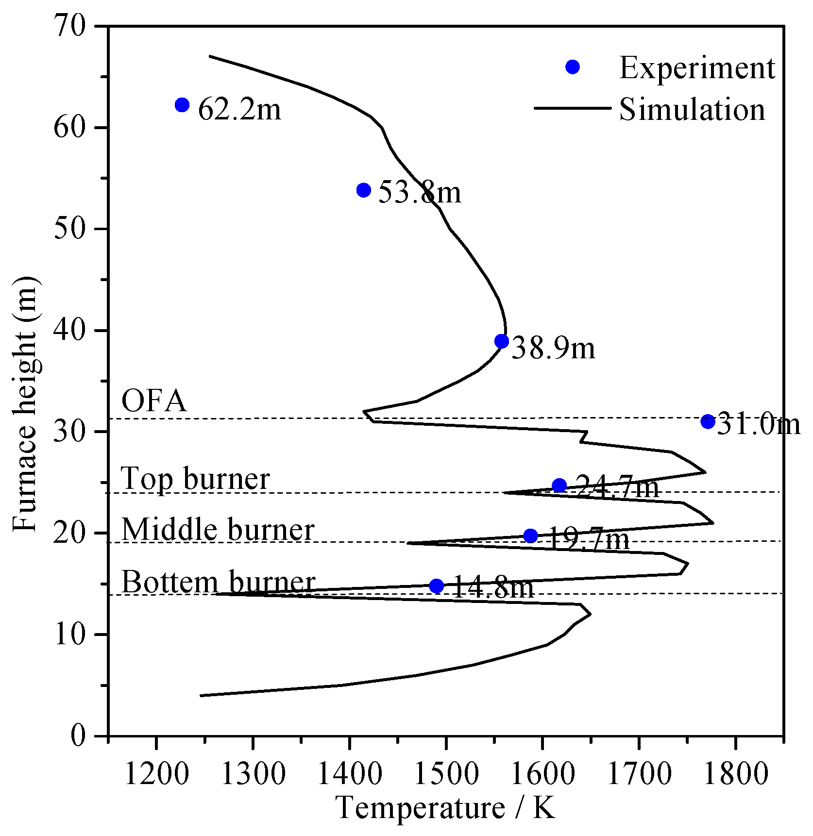
4.1. Validation of Numerical Models

Model selection can give rise to different simulation results, and therefore, the validity of the numerical calculation model must first be verified by the comparison to the in-situ test data. The furnace temperature from the simulation and the measured values of the in-situ boiler is described in Figure 4. The average temperature of the simulation results along the furnace height was in accordance with the temperature variation of the measured values. The average relative deviation between the simulated and measured values was 6.4% and from the perspective of practical applications, the deviation of certain degree was acceptable. Table 3 shows the comparisons of some indicators at the furnace outlet between simulation and experimental results. In Table 3, the simulated and measured data at the furnace outlet is consistent. Therefore, it can be inferred that the calculation model selected is reasonable and the simulation results are credible.

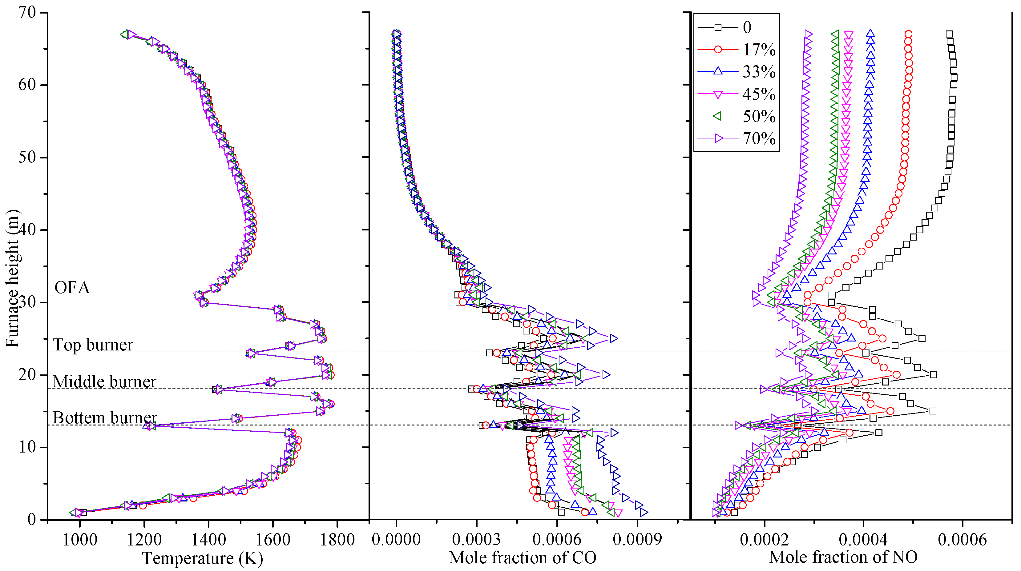
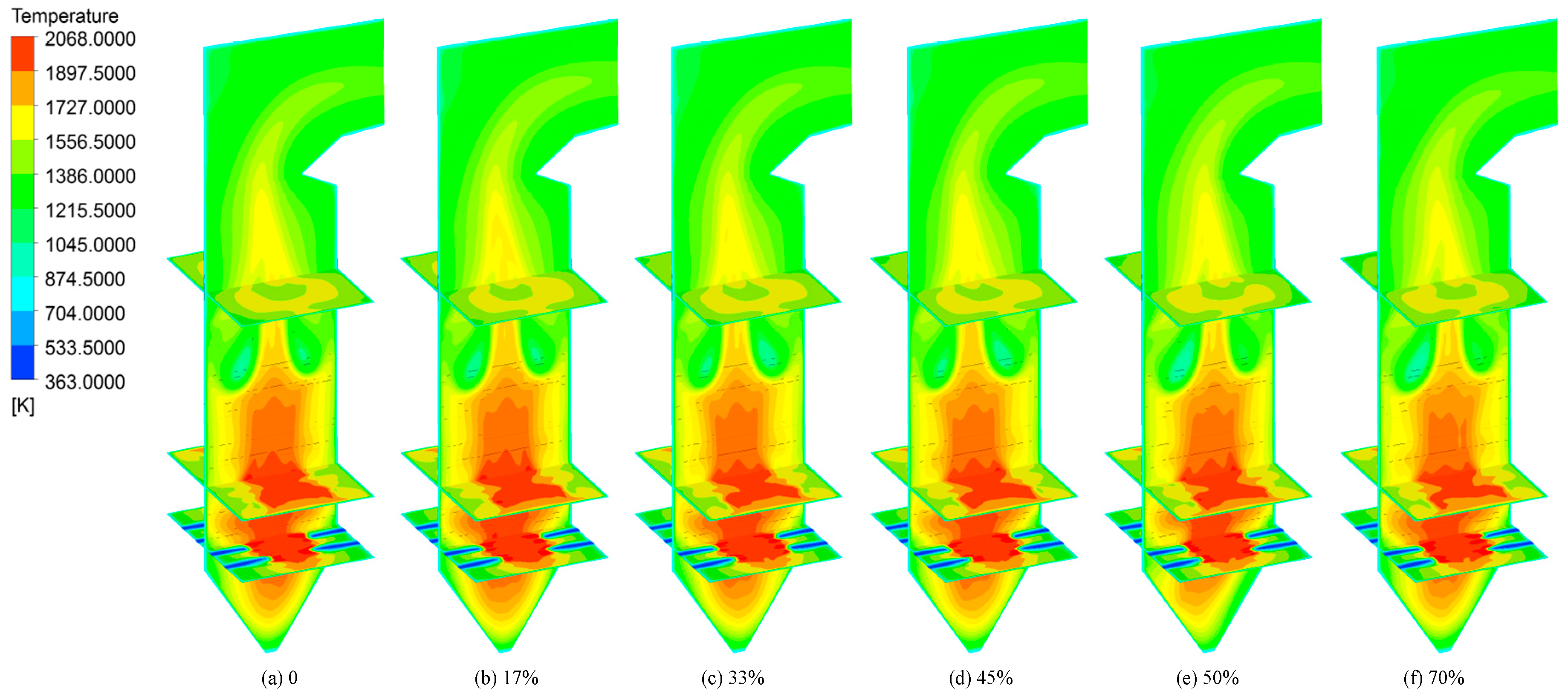
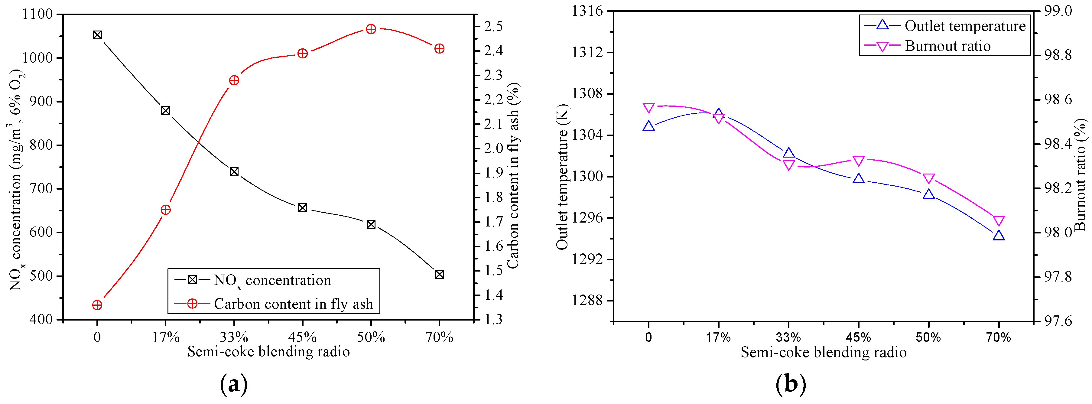
4.2. Influence of Semi-coke Blending Ratio

Firstly, the influence of semi-coke blending ratio on the combustion efficiency and NOx emissions at the furnace outlet was investigated. Under the premise that the fuel heat into the furnace was kept unchanged, the ratio of semi-coke was set as 0%, 17%, 33%, 45%, 50%, and 70%, respectively. Here, the semi-coke and lean coal were blended before the coal mill and ground into powder, which was then sent into the furnace for co-combustion; so-called “out-furnace blending”. The excess air coefficient in primary combustion zone was set to 0.75, and the total excess air coefficient was 1.14.
The temperature distributions within the furnace at various blending ratios of semi-coke are illustrated in Figure 5. The average temperature first increased and then decreased with an increase in the furnace height; the temperature at the flame center was relative high. As shown in Figure 6, the changes of average temperature, CO, and NO mole fraction along the furnace height under various blending ratios of the semi-coke can be depicted more intuitively. The average temperature under various semi-coke blending ratios showed limited difference. This is mainly because the fuel was homogeneous and the net calorific value of semi-coke and coal was quite close (25.35 MJ/kg for semi-coke and 24.36 MJ/kg for coal). Due to the injection of the air and pulverized coal with low temperature, the average furnace temperature at the burner position dropped dramatically. However, the air could promote the pulverized coal combustion, and then the average furnace temperature increased once again. When the combustion reaction was nearly completed, the average temperature decreased with the heat transfer between the platen superheater and flue gas in the furnace. When the blending ratio of semi-coke was enhanced, the corresponding CO concentration on each cross-section was elevated. It is reasonable to believe that the combustion performance of semi-coke was inferior to that of lean coal mainly due to the lower content of volatile matter. Since the low-NOx burners were utilized in the boiler, the center of main combustion zone formed a rich-fuel and low-oxygen atmosphere through staged combustion, where the oxygen supplied for the pulverized coal combustion was deficient. The center of main combustion zone presents a reducing atmosphere and a large amount of CO was generated in the combustion of pulverized coal. From the comparison of CO mole fraction under different cases at the same furnace height, the higher the semi-coke blending ratio was, the higher the CO concentration in the primary combustion zone.
Some indicators at the outlet of the furnace are compared in Figure 7. With an increase in the semi-coke blending ratio, the NOx emission at the furnace outlet decreased. The mole fraction of NO decreased with the blending ratio of semi-coke increased at the same furnace height as shown in Figure 6, which is consistent with the trend of NOx concentration. The lower content of nitrogen in semi-coke than that in coal might be a reason. With more semi-coke blended, the fuel contains less nitrogen and the generation of fuel NOx is reduced accordingly. Because the coal properties of semi-coke and lean coal are similar, the NOx emission of blended fuel combustion is positively related to the nitrogen content within fuel for the co-combustion of “out-furnace blending” method, but exhibits no-additive behaviors. Furthermore, with more CO produced in the main combustion zone, the atmosphere is more reductive and more already-formed NOx could be reduced, leading to the decline of the overall NOx emission. The present simulation and the results obtained by Zhang et al. [34] that the NOx generation could be reduced by blending semi-coke when the content of nitrogen in semi-coke was lower than that in other type of coal are basically identical. When blending semi-coke reaches 70%, the NOx concentration was nearly half lower than that with individual lean coal. The carbon content in fly ash shows a generally increasing tendency with the share of semi-coke, which is firstly almost linearly raised (the proportion of semi-coke ≤ 33%) and then establishes only a slight increase with the further rise of semi-coke content. The semi-coke is difficult to burn out from the view of low volatile content. The burnout ratio establishes a slight decrease tendency with the proportion of semi-coke blended rises. The temperature at the furnace outlet yields a reduction tendency with the semi-coke blending ratio increased. Although the calorific value of semi-coke is a little higher than that of lean coal, less heat can be released when the same amount of oxygen is consumed on account of lower H/C ratio of semi-coke. Fortunately, the temperature variation at the furnace outlet was defined within approximately 10 K as the proportion of semi-coke changes from 0% to 70%. Hence, blending semi-coke with lean coal has limited influences on the performance of the heat transfer in the downstream convection zone, but generates significant impact on NOx emission and burnout behavior in full-scale power plants.

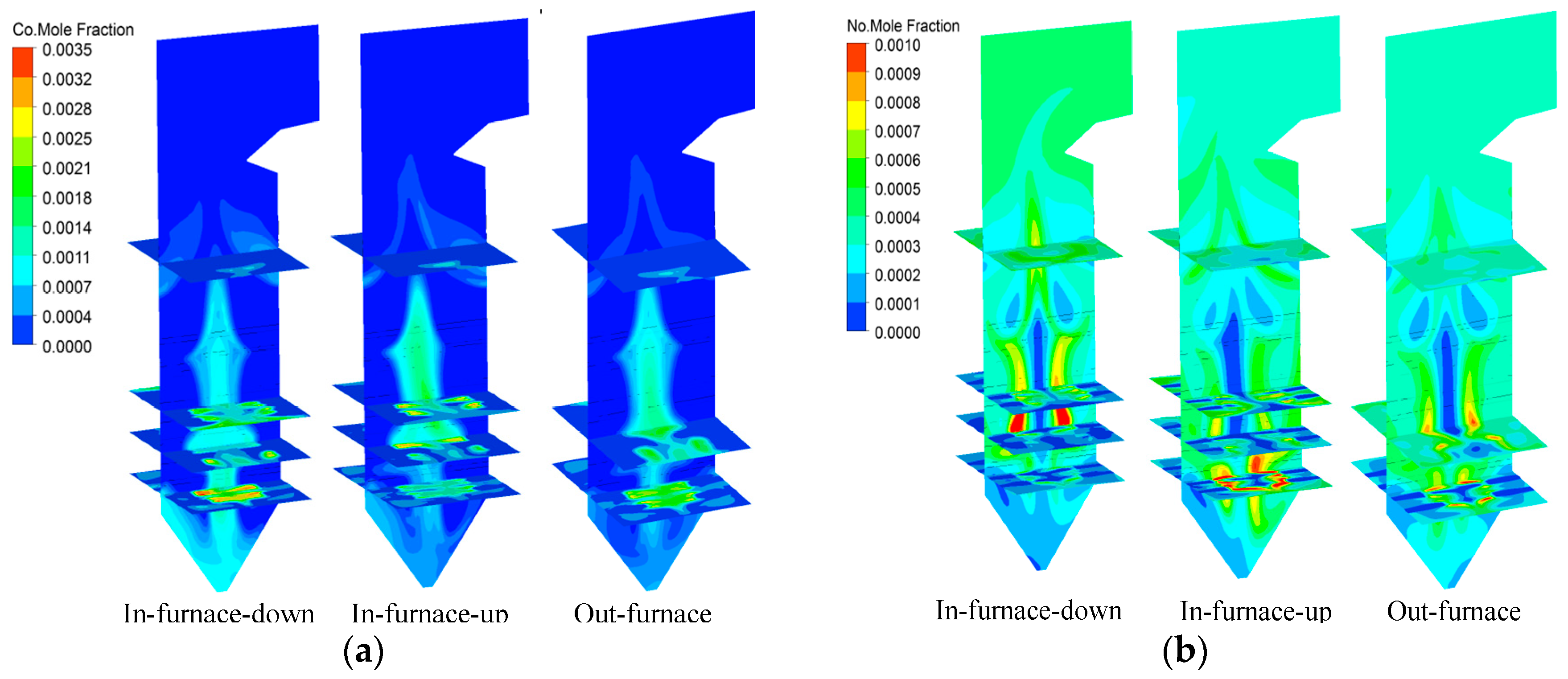
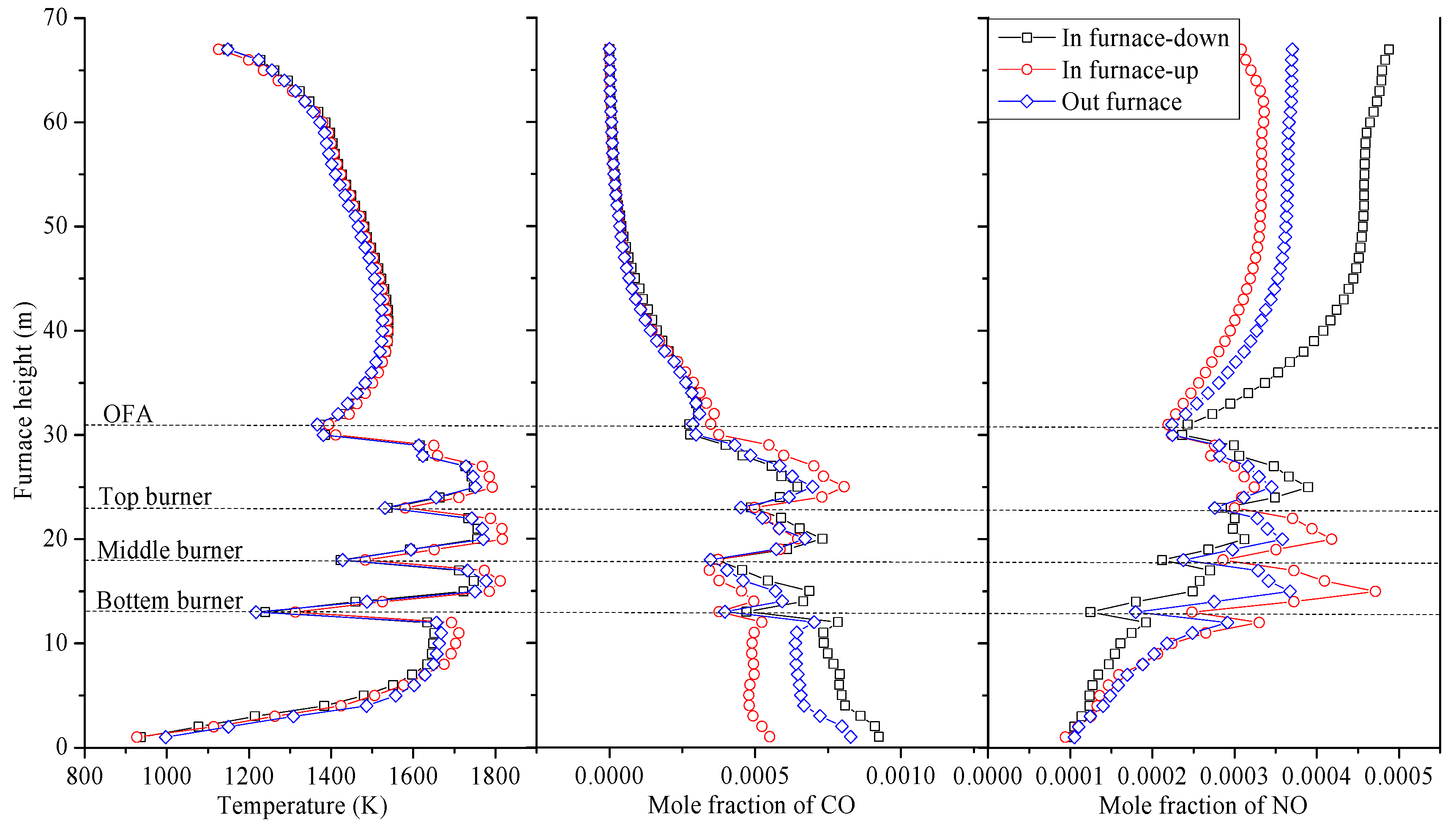
4.3. Influence of Injection Strategies of Semi-coke

For the “in-furnace blending” method, the semi-coke and coal are not mixed in advance before entering into the furnace but blended within the furnace instead. Hence, the injection strategies of the semi-coke can be varied and are very likely to generate significant effect on the NOx generation and combustion efficiency. Here, two options of the injection position of semi-coke were compared with the blending ratio of semi-coke kept unchanged as 45%. For one case, the semi-coke was injected into the furnace from all upper nozzles and the middle four nozzles in the middle layer, which was expressed as the “in-furnace-up” case. The other case was when the semi-coke was injected from all lower nozzles and the outer four nozzles in the middle layer, expressed as the “in-furnace-down” case. In addition, the “out-furnace blending” case with 45% semi-coke was further analyzed for the comparison to elucidate the impact of blending method on the combustion performance of blended fuels.
It can be seen from Figure 8 that the average temperature along the height of the furnace was elevated as the height of semi-coke injection position was raised. Given that the semi-coke was injected at a higher position, it could be well-ignited and relieve the slagging at the bottom of the furnace. Consequently, the overall burnout situation of pulverized coal could be improved and the heat generated from combustion could also be enhanced to some extent, which induces an increase in the average furnace temperature. The mole fraction of CO at the furnace bottom shows a large difference, which is the biggest in the “in-furnace-down” case, but is the smallest in the “in-furnace-up” case. The temperature is relatively low, and carbon cannot be completely burned to generate carbon monoxide. The content of carbon in semi-coke is higher than that in lean coal, leading to more carbon monoxide generated in the “in-furnace-down” case than that in other cases. The mole fraction of CO in three different injection strategies of semi-coke tends to be consistent with the injection of the OFA. It can also be observed from Figure 8 that as the semi-coke is injected from the lower burners, the NO mole fraction increases most significantly beyond the position of the OFA burner in comparison with other two blending strategies. As displayed in Figure 9, there is a negative correlation between the CO concentration and the NO concentration at the injection position of semi-coke. Table 4 depicts several operation indices at the furnace outlet under various injection strategies of semi-coke. The NOx emission in the “in-furnace-down” case is evidently higher than that in the “in-furnace-up” case. When the semi-coke is injected from the upper burners, the NOx emission at the furnace outlet is reduced by 200 mg/m3 compared with the case of “in-furnace-down”, and is abated by 44 mg/m3 in contrast to the condition of “out-furnace blending”. The decrease of the semi-coke injection height can bring about an increase of the fuel-NOx production in the furnace because the nitrogen in semi-coke is lower than that in lean coal. The residence time of NOx is prolonged and the reduction of NOx increases. In addition, the unburned carbon in the middle and upper of the burner zone can be increased by the injection of semi-coke from the upper burners, which leads to that the amount of generation of NOx can be effectively reduced. The carbon content in fly ash rises with the increasing height of injecting semi-coke. When lean coal is burned in the lower burners, the average temperature is enhanced and the combustion of semi-coke is promoted, which makes the semi-coke not easy to slag, but causes the rise of carbon content in fly ash. When the injection position of semi-coke increases, the outlet temperature is elevated. In addition, the outlet temperature in the “out-furnace” case was larger than that in the “in-furnace” cases although the temperature difference is within 10 K. The burnout ratio is improved by the decline of semi-coke injection height owing to the difficulty in burning semi-coke. The pulverized coal injected from different burners had insignificant difference in the “out-furnace” cases, which caused the combustion atmosphere in the furnace to be better than in the “in-furnace” cases. However, the injection strategies of semi-coke had little impact on the outlet temperature and burnout ratio.

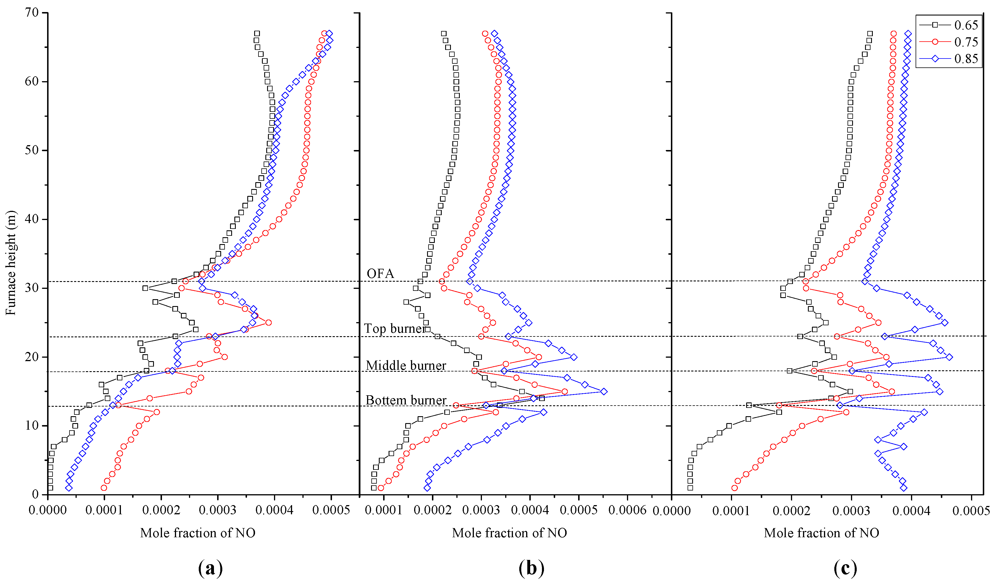
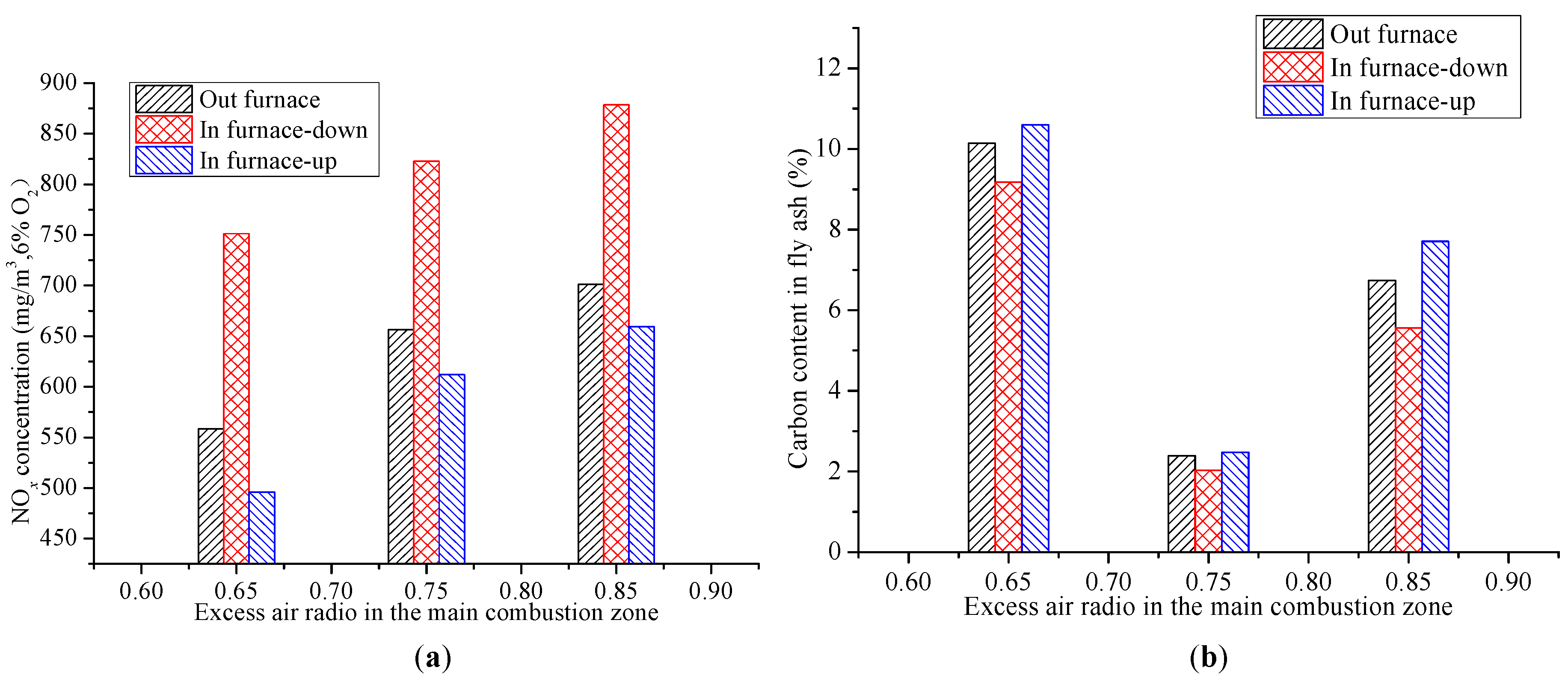
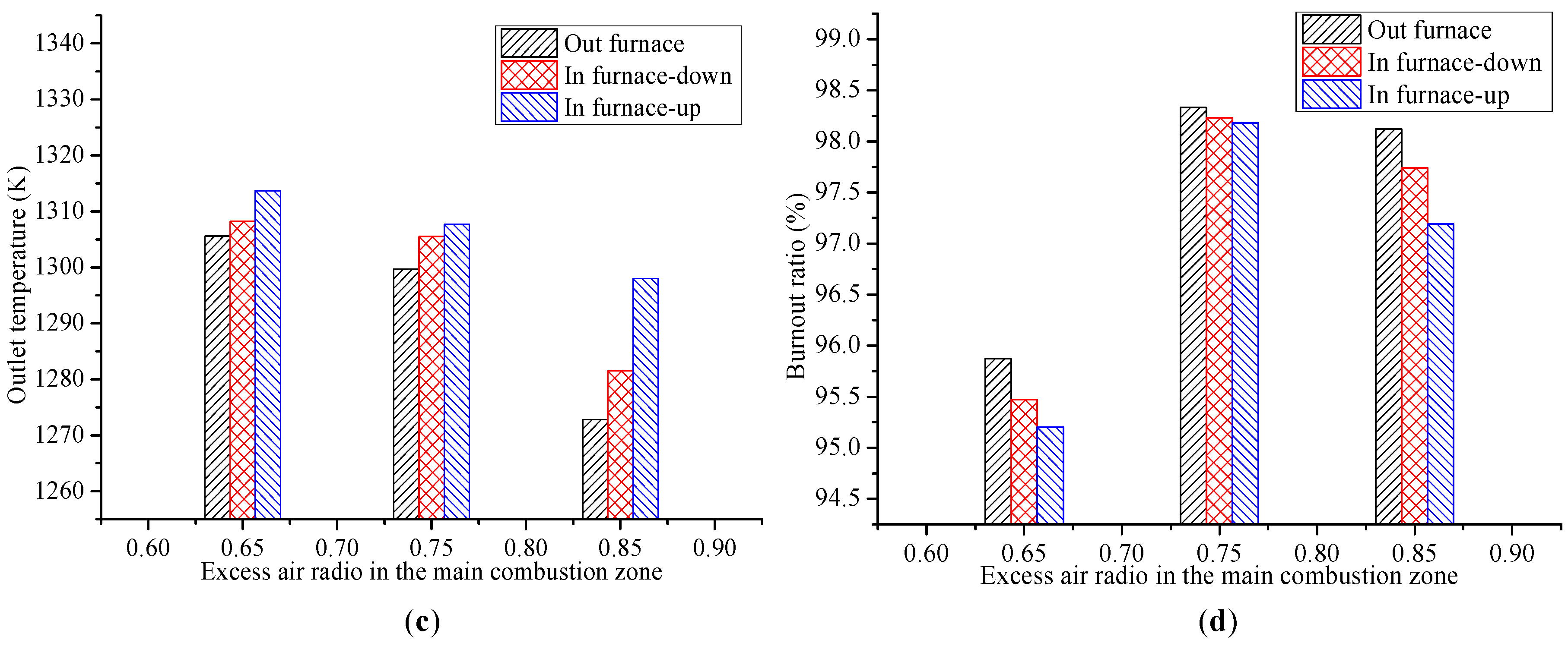
4.4. Influence of Excess Air Ratios in the Main Combustion Zone

The excess air ratio in primary combustion zone has significant impacts on the boiler operation performance. For the convenience of expression, the excess air ratio in primary combustion zone is defined as α1. Figure 10 illustrates the average temperature distribution within furnace in the cases that the α1 varies among 0.65, 0.75, and 0.85 under three blending methods with the semi-coke blending ratio of 45%. The average temperature distribution within the furnace exhibited relative good symmetry. The average temperature within furnace increased first and then decreased with the enhancement in α1. The overall temperature within the furnace in the “out-furnace” case was higher than that in the “in-furnace” cases. The pulverized coal can be combusted well and the temperature within furnace was enhanced with more air injected. Since the temperature of the air injected was much lower than the temperature within furnace, too much air brought about a decrease of the temperature within the furnace. As shown in Figure 11, the mole fraction of NO had an increase and the trend flattened out with the increase of α1. The change trend of the NO mole fraction in the “in-furnace- up” case was similar to that in the “out-furnace” case, while the mole fraction of NO in the “in-furnace down” case established a clear increase tendency with the injection of OFA. Figure 12 displays several essential indices under various α1. With the increase in α1, the NOx concentration at the furnace outlet showed an increasing trend and various blending methods shared the same trend. As the α1 rose, more air was injected in the primary combustion zone, since the total air remained constant. The unburned carbon could be consumed and release more heat, which led to the increase of the NOx production. In addition, the high concentration of oxygen resulted in the abatement of reducing atmosphere. Hence, the reduction of NOx declined, which is consistent with the tendency of NOx concentration as shown in Figure 11. When the α1 rises, the change trend of the carbon content in fly ash and burnout ratio was opposite. Compared with the case where the α1 is 0.65, the air injected into the furnace became less when the α1 became 0.65, leading to the anoxic combustion phenomenon. When the α1 increased to 0.85, large quantities of air in low temperature were sprayed into the primary combustion zone, resulting in the decline of the temperature within furnace and the delay of ignition. Hence, the degree of incomplete combustion of pulverized coal increased. The average temperature at the furnace outlet dropped with the increasing α1. When the α1 is 0.85, a drop of the outlet temperature in the “out-furnace” case was dramatic, larger than those in the “in-furnace” cases. The NOx concentration increased by nearly 100 mg/m3, while the burnout ratio increased significantly and the carbon content in fly ash went down to 1/5 when the α1 was changed from 0.65 to 0.75. When the α1 increased to 0.85, the NOx concentration increased by nearly 50 mg/m3 and the carbon content in fly ash increased more than three times, while the burnout ratio only showed a slight difference. The research of Wu et al. [35] illustrated that when the ratio of OFA was increased, the boiler combustion efficiency was reduced, while NOx concentration was also reduced due to the enhanced the effects of the air staged combustion. Hence, a balance must be found between the NOx concentration and the boiler efficiency. When the semi-coke blending ratio is 45%, the optimal α1 in this study is 0.75 to achieve low NOx concentration based on good operation performance of wall-fired boiler.

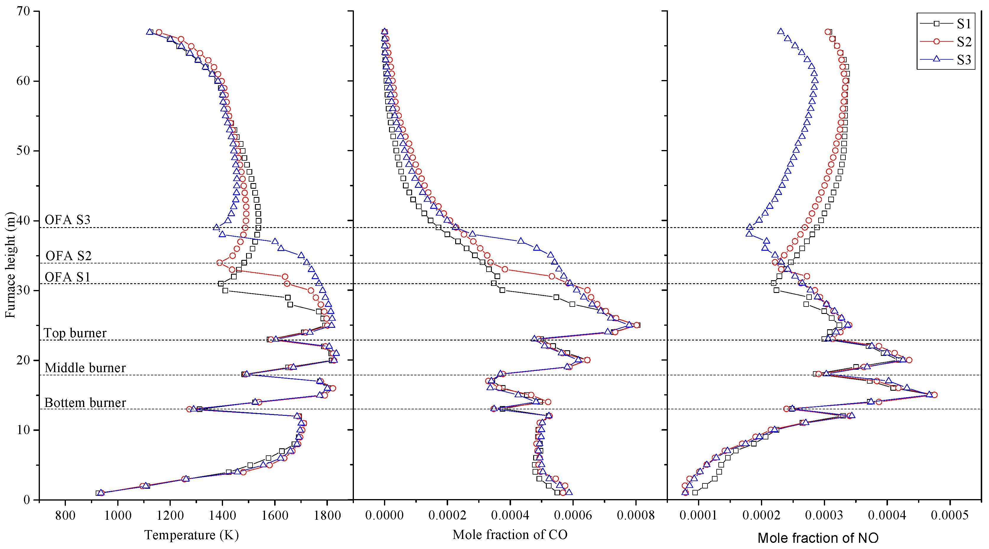
4.5. Influence of OFA Arrangement

The OFA arrangement possibly generated influences on the NOx emissions and boiler co-combustion performance. Figure 13 depicts the average temperature and species concentrations along the furnace height, with the blending ratio of semi-coke being 45%. It can be seen in Figure 13 that the average temperature and mole fraction of CO and NO in the main combustion zone exhibited unapparent association with the OFA arrangement. However, above the main combustion zone, each condition shows its own characteristics because of the different positions of OFA nozzles. The injection of OFA with low temperature brought about a decrease in the average temperature within the furnace, and the downward trend slowed down with the increase of the OFA position. The injected OFA diluted the CO and NO concentrations, and promoted the combustion of unburned pulverized coal, leading to a decrease of CO and an increase of NO. The uptrend of the NOx production was mitigated by deferring the injection of OFA. Table 5 depicts some indicators at the furnace outlet under various OFA arrangements. The NOx concentration at the furnace outlet showed a downward trend and there was a tendency for the decrease to flatten out while the height of OFA increased. The increase of the height of OFA caused the extension of the reduction zone. The deficiency of oxygen in the reduction zone prolonged the residence time of the NOx generated in the furnace. Hence, the conversion of NOx to N2 was facilitated, which suppressed the formation of NOx and reduced the average NOx concentration at the furnace outlet. Ribeirete et al. [36] indicated that the NOx emissions decreased as the OFA position gradually moved away from the main combustion zone, which was consistent with the present simulation results. The yield of the carbon content in fly ash has a substantial increase as the height of OFA rises. As the distance between the uppermost burners and the OFA burners was enlarged, the time that coke spends was shortened. Compared with the case of the original OFA position, the NOx concentration was decreased by 82 mg/m3 and the carbon content in fly ash was increased more than double when OFA was injected in the height of S2. In addition, if the carbon content in fly ash was relatively high, it showed a negative impact on the application of ash. As the height of OFA injected rose, the CO and unburned pulverized coal consume in the burnout zone and the burnout zone was closer to the furnace outlet, which caused the average outlet temperature to increase from 1307.7 K to 1335.2 K. The burnout ratio under various OFA arrangements showed slight difference because the burnout ratio was affected by the combustion in primary combustion zone. Hence, the carbon content in fly ash and NOx emission were taken into account comprehensively to select an appropriate height of OFA to ensure the NOx emission can be reduced without obvious impact on combustion efficiency.

5. Conclusions

In the present study, the NOx generation and combustion characteristics of co-firing lean coal and semi-coke in a 600 MW supercritical wall-fired boiler were firstly studied by means of numerical simulation. Some strategies for the operation optimization were further discussed after the simulation validation by the in-situ data. The simulation results suggested that co-firing lean coal and semi-coke in the wall-fired boiler is a feasible measure. As the blending ratio of semi-coke increased, the NOx emission could be reduced without notable increase of the carbon content in fly ash when the nitrogen in semi-coke is lower than that in lean coal. The blending methods (in-furnace versus out-furnace) had certain impacts on the NOx emission and carbon content in fly ash, while the in-furnace blending method showed more flexibility in co-firing adjustment. The upper burners were recommended to inject semi-coke due to the difference of the coal characteristics in the “in-furnace” cases; the NOx emissions in the “in-furnace-up” case were even lower than that in the “out-furnace” case. However, the combustion efficiency in the “out-furnace” cases was higher than that in the “in-furnace” cases at the same blending ratio of semi-coke. The optimal α1 was 0.75 to achieve a relatively low NOx concentration with good combustion performance. The operational performance of the boiler co-firing semi-coke was greatly affected by the arrangement of OFA as well. The NOx concentration under the S3 position of OFA was 80 mg/m3 lower than that under the S1 OFA position, while the carbon content in fly ash under the S3 position of OFA was more than double of that in the original position. The appropriate increase of the height of OFA could generate a further decrease in the NOx emission with insignificant increase of the carbon content in fly ash when the α1 and the blending method were optimal.

Author Contributions

Conceptualization, C.W.; Methodology, Q.F. and Q.L.; Validation, C.W. and Y.D.; Formal analysis, C.W. and P.W.; Investigation, Q.F., Q.L., L.Z., and J.Z.; Writing—original draft preparation, C.W. and Q.F.; Writing—review and editing, Q.W. and D.C.; Supervision, D.C.; Project administration, C.W.; Funding acquisition, C.W.

Funding

This research was funded by the National Key R&D Program of China, grant number 2017YFB0602003.

Acknowledgments

The authors acknowledge financial support from the National Key R&D Program of China (2017YFB0602003).

Conflicts of Interest

The authors declare no conflict of interest.

References

  1. Yao, Y.; Zhu, J.G.; Lu, Q.G. Experimental study on nitrogen transformation in combustion of pulverized semi-coke preheated in a circulating fluidized bed. Energy Fuels 2015, 29, 3985–3991. [Google Scholar] [CrossRef]
  2. Xie, K.C.; Li, W.Y.; Zhao, W. Coal chemical industry and its sustainable development in China. Energy 2010, 35, 4349–4355. [Google Scholar] [CrossRef]
  3. Wang, C.A.; Wu, S.; Lv, Q.; Liu, X.; Chen, W.F.; Che, D.F. Study on correlations of coal chemical properties based on database of real-time data. Appl. Energ. 2017, 204, 1115–1123. [Google Scholar] [CrossRef]
  4. Ji, X.F.; Song, D.Y.; Zhao, H.T.; Li, Y.B.; He, K.K. Experimental analysis of pore and permeability characteristics of coal by low-field NMR. Appl. Sci. 2018, 8, 1374. [Google Scholar] [CrossRef]
  5. Lee, B.H.; Bae, J.S.; Choi, Y.C.; Jeon, C.H. Combustion behavior of low-rank coal impregnated with glycerol. Biomass Bioenergy 2016, 87, 122–130. [Google Scholar] [CrossRef]
  6. Jayaraman, K.; Kok, M.V.; Gokalp, I. Pyrolysis, combustion and gasification studies of different sized coal particles using TGA-MS. Appl. Therm. Eng. 2017, 125, 1446–1455. [Google Scholar] [CrossRef]
  7. Kok, M.V. Simultaneous thermogravimetry–calorimetry study on the combustion of coal samples: Effect of heating rate. Energy Convers. Manag. 2012, 53, 40–44. [Google Scholar] [CrossRef]
  8. Liu, G.Y.; Zhang, Y.T.; Cai, J.T.; Zhou, A.N.; Dang, Y.Q.; Qiu, J.S. A strategy for regulating the performance of DCFC with semi-coke fuel. Int. J. Hydrog. Energy 2018, 43, 7465–7472. [Google Scholar] [CrossRef]
  9. Man, C.B.; Zhu, X.; Gao, X.Z.; Che, D.F. Combustion and pollutant emission characteristics of lignite dried by low temperature air. Dry. Technol. 2014, 33, 616–631. [Google Scholar] [CrossRef]
  10. Krzesińska, M.; Pusz, S.; Smędowski, Ł. Characterization of the porous structure of cokes produced from the blends of three Polish bituminous coking coals. Int. J. Coal Geol. 2009, 78, 169–176. [Google Scholar] [CrossRef]
  11. Wang, C.A.; Wang, P.Q.; Zhao, L.; Du, Y.B.; Che, D.F. Experimental study on NOx reduction in oxy-fuel combustion using synthetic coals with pyridinic or pyrrolic nitrogen. Appl. Sci. 2018, 8, 2499. [Google Scholar] [CrossRef]
  12. Jayaraman, K.; Kok, M.V.; Gokalp, I. Thermogravimetric and mass spectrometric (TG-MS) analysis and kinetics of coal-biomass blends. Renew. Energy 2017, 101, 293–300. [Google Scholar] [CrossRef]
  13. Fan, B.; Wen, C.; Zeng, X.P.; Wu, J.Q.; Yu, X. Emission behaviors of inorganic ultrafine particles during Zhundong coal oxy-fuel combustion with characterized oxygen input fractions comparable to air combustion. Appl. Sci. 2018, 8, 1486. [Google Scholar] [CrossRef]
  14. Wang, C.A.; Wang, P.Q.; Du, Y.B.; Che, D.F. Experimental study on effects of combustion atmosphere and coal char on NO2 reduction under oxy-fuel condition. J. Energy Inst. 2019. [Google Scholar] [CrossRef]
  15. Ouyang, Z.Q.; Zhu, J.G.; Lu, Q.G.; Yao, Y.; Liu, J.Z. The effect of limestone on SO2 and NOx emissions of pulverized coal combustion preheated by circulating fluidized bed. Fuel 2014, 120, 116–121. [Google Scholar] [CrossRef]
  16. Man, C.B.; Zhu, J.G.; Ouyang, Z.Q.; Liu, J.Z. Experimental study on combustion characteristics of pulverized coal preheated in a circulating fluidized bed. Fuel Process. Technol. 2018, 172, 72–78. [Google Scholar] [CrossRef]
  17. Zhang, J.W.; Chen, K.; Wang, C.A.; Xiao, K.; Xu, X.Y.; Che, D.F. Optimization of separated overfire air system for a utility boiler from a 3-MW pilot-scale facility. Energy Fuels 2013, 27, 1131–1140. [Google Scholar] [CrossRef]
  18. Lu, Y.; Wang, Y.; Xu, Y.; Li, Y.; Hao, W.; Zhang, Y. Investigation of ash fusion characteristics and migration of sodium during co-combustion of Zhundong coal and oil shale. Appl. Therm. Eng. 2017, 121, 224–233. [Google Scholar] [CrossRef]
  19. Wang, C.A.; Liu, Y.H.; Zhang, X.M.; Che, D.F. A study on coal properties and combustion characteristics of blended coals in Northwestern China. Energy Fuels 2011, 25, 3634–3645. [Google Scholar] [CrossRef]
  20. Lee, B.H.; Kim, S.G.; Song, J.H.; Chang, Y.J.; Jeon, C.H. Influence of coal blending methods on unburned carbon and NO emissions in a drop-tube furnace. Energy Fuels 2011, 25, 5055–5062. [Google Scholar] [CrossRef]
  21. Lee, B.H.; Song, J.H.; Kim, R.G.; Kim, S.G.; Kim, Y.G.; Chang, Y.J.; Jeon, C.H. Simulation of the influence of the coal volatile matter content on fuel NO emissions in a drop-tube furnace. Energy Fuels 2010, 24, 4333–4340. [Google Scholar] [CrossRef]
  22. Ikeda, M.; Makino, H.; Morinaga, H.; Higashiyama, K.; Kozai, Y. Emission characteristics of NOx and unburned carbon in fly ash during combustion of blends of bituminous/sub-bituminous coals. Fuel 2003, 82, 1851–1857. [Google Scholar] [CrossRef]
  23. Li, D.B.; Lv, Q.; Feng, Y.G.; Wang, C.A.; Liu, X.; Chen, K.; Xu, K.; Zhong, J.; Che, D.F. Effects of coal blending and operating conditions on combustion and NOx emission characteristics in a tangentially-fired utility boiler. Energy Procedia 2017, 105, 4015–4020. [Google Scholar] [CrossRef]
  24. Du, Y.B.; Wang, C.A.; Wang, P.Q.; Meng, Y.; Wang, Z.C.; Yao, W.; Che, D.F. Computational fluid dynamics investigation on the effect of co-firing semi-coke and bituminous coal in a 300 MW tangentially fired boiler. Proc. Inst. Mech. Eng. A 2018. [Google Scholar] [CrossRef]
  25. Liu, H.; Liu, Y.H.; Yi, G.Z.; Li, N.; Che, D.F. Effects of air staging conditions on the combustion and NOx emission characteristics in a 600 MW wall fired utility boiler using lean coal. Energy Fuels 2013, 27, 5831–5840. [Google Scholar] [CrossRef]
  26. Li, D.B.; Lv, Q.; Feng, Y.X.; Wang, C.A.; Liu, X.; Du, Y.B.; Zhong, J.; Che, D.F. Numerical study of co-firing biomass with lean coal under air–fuel and oxy-fuel conditions in a wall-fired utility boiler. Energy Fuels 2017, 31, 5344–5354. [Google Scholar] [CrossRef]
  27. Liu, H.; Tang, C.L.; Zhang, L.; Zhu, H.; Li, N.; Che, D.F. Effect of two-level over-fire air on the combustion and NOx emission characteristics in a 600 MW wall-fired boiler. Numer. Heat Tr. 2015, 68, 993–1009. [Google Scholar] [CrossRef]
  28. Tan, P.; Ma, L.; Xia, J.; Fang, Q.Y.; Zhang, C.; Chen, G. Co-firing sludge in a pulverized coal-fired utility boiler: Combustion characteristics and economic impacts. Energy 2017, 119, 392–399. [Google Scholar] [CrossRef]
  29. Du, Y.B.; Wang, C.A.; Lv, Q.; Li, D.B.; Liu, H.; Che, D.F. CFD investigation on combustion and NO emission characteristics in a 600 MW wall-fired boiler under high temperature and strong reducing atmosphere. Appl. Therm. Eng. 2017, 126, 407–418. [Google Scholar] [CrossRef]
  30. Chen, S.N.; He, B.S.; He, D.; Cao, Y.; Ding, G.C.; Liu, X.; Duan, Z.P.; Zhang, X.; Song, J.G.; Li, X.Z. Numerical investigations on different tangential arrangements of burners for a 600 MW utility boiler. Energy 2017, 122, 287–300. [Google Scholar] [CrossRef]
  31. Álvarez, L.; Yin, C.; Riaza, J.; Pevida, C.; Pis, J.J.; Rubiera, F. Oxy-coal combustion in an entrained flow reactor: Application of specific char and volatile combustion and radiation models for oxy-firing conditions. Energy 2013, 62, 255–268. [Google Scholar] [CrossRef]
  32. Zhang, J.; Prationo, W.; Zhang, L.; Zhang, Z.X. Computational fluid dynamics modeling on the air-firing and oxy-fuel combustion of dried victorian brown coal. Energy Fuels 2013, 27, 4258–4269. [Google Scholar] [CrossRef]
  33. Drosatos, P.; Nikolopoulos, N.; Agraniotis, M.; Kakaras, E. Numerical investigation of firing concepts for a flexible Greek lignite-fired power plant. Fuel Process. Technol. 2016, 142, 370–395. [Google Scholar] [CrossRef]
  34. Zhang, J.; Wang, Q.Y.; Wei, Y.J.; Zhang, L. Numerical modeling and experimental investigation on the use of brown coal and its beneficiated semicoke for coal blending combustion in a 600 MWe utility furnace. Energy Fuels 2015, 29, 1196–1209. [Google Scholar] [CrossRef]
  35. Wu, Y.P.; Wen, Z.Y.; Shen, Y.L.; Fang, Q.Y.; Zhang, C.; Chen, G. Effects of over fire air on the combustion and NOx emission characteristics of a 600 MW opposed swirling fired boiler. Adv. Mater. Res. 2012, 512–515, 2135–2142. [Google Scholar] [CrossRef]
  36. Ribeirete, A.; Costa, M. Impact of the air staging on the performance of a pulverized coal fired furnace. Proc. Combust. Inst. 2009, 32, 2667–2673. [Google Scholar] [CrossRef]
Figure 1. The detailed configuration of the wall-fired boiler. OFA: over fire air.
Applsci 09 00889 g001
Figure 2. The mesh system of the wall fired boiler.
Applsci 09 00889 g002
Figure 3. Evaluation of the grid independence.
Applsci 09 00889 g003
Figure 4. The average temperature within the furnace of the in-situ test and simulation results.
Applsci 09 00889 g004
Figure 5. The temperature contours within furnace at various semi-coke blending ratios.
Applsci 09 00889 g005
Figure 6. The average temperature and species concentrations along the height of the furnace at various semi-coke blending ratios.
Applsci 09 00889 g006
Figure 7. Some indicators at the furnace outlet for out-furnace blending combustion under various semi-coke blending ratios; (a) the NOx concentration and carbon content in fly ash; (b) the outlet temperature and burnout ratio.
Applsci 09 00889 g007
Figure 8. The average temperature and species concentrations along the height of furnace.
Applsci 09 00889 g008
Figure 9. The contours in furnace under various injection strategies of semi-coke; (a) the mole fraction of CO; (b) the mole fraction of NO.
Applsci 09 00889 g009
Figure 10. The temperature contours within furnace at various α1.
Applsci 09 00889 g010
Figure 11. The mole fraction of NO along the height of furnace; (a) in-furnace-down; (b) in-furnace-up; (c) out-furnace.
Applsci 09 00889 g011
Figure 12. Some indicators at the furnace outlet under various α1; (a) the NOx concentration; (b) the carbon content in fly ash; (c) The outlet temperature; (d) The burnout ratio
Applsci 09 00889 g012aApplsci 09 00889 g012b
Figure 13. The average temperature and species concentrations along the height of furnace (S1 refers to the original OFA nozzles of the boiler at the height of 31 m and S2 and S3 refer to the OFA nozzles at the height of 34 m and 39 m, respectively).
Applsci 09 00889 g013
Table 1. The ultimate and proximate analysis of the fuels.
ParameterUltimate Analysis (wt %)Proximate Analysis (wt %)
CarHarOarNarSarMarAarVarFCar
Lean coal64.243.552.621.150.335.8822.2210.3861.52
Semi-coke74.421.401.970.910.408.1012.808.2270.88
Table 2. Detailed operation conditions of simulation cases.
CaseBlending RatioMass Flow Rate (Kg/s)Blending ModelInjection Strategy of Semi-Cokeα1OFA Position
CoalCokeAir
T1062.30601.84--0.75S1
1062.30601.84--0.75S1
21761.87603.18Out-furnace-0.75S1
33361.48604.43Out-furnace-0.75S1
44561.18605.36Out-furnace-0.75S1
55061.06605.75Out-furnace-0.75S1
67060.58607.26Out-furnace-0.75S1
74561.18605.36Out-furnace-0.65S1
84561.18605.36Out-furnace-0.85S1
94533.6527.53605.36In-furnacedown0.75S1
104533.6527.53605.36In-furnacedown0.65S1
114533.6527.53605.36In-furnacedown0.85S1
124533.6527.53605.36In-furnaceup0.75S1
134533.6527.53605.36In-furnaceup0.65S1
144533.6527.53605.36In-furnaceup0.85S1
154533.6527.53605.36In-furnaceup0.75S2
164533.6527.53605.36In-furnaceup0.75S3
Table 3. Some indicators at the furnace outlet under the in-situ test and simulation results.
IndicatorExperimental ValueSimulation Result
Carbon content in fly ash (%)4.974.58
NOx emission (mg/m3 6% O2)508505
Table 4. Some indicators at the furnace outlet under various injection strategies of semi-coke.
CasesNOx Concentration (mg/m3, 6% O2)Carbon Content in Fly Ash (%)Outlet Temperature (K)Burnout Ratio (%)
out-furnace 656.372.29 1299.7098.33
in-furnace-down822.762.031305.5098.23
In-furnace-up612.012.48 1307.7098.18
Table 5. Some indicators at the furnace outlet under various OFA arrangements.
ParametersNOx Concentration (mg/m3, 6% O2)Carbon Content in Fly Ash (%)Outlet Temperature (K)Burnout Ratio (%)
S1612.01 2.48 1307.70 98.18
S2573.56 4.71 1319.40 97.63
S3530.00 5.37 1335.20 97.48

