Acquisition of Multi-Modal Images of Structural Modifications in Glass with Programmable LED-Array-Based Illumination

Ritsumeikan University, Department of Electrical & Electronic Engineering, College of Science and Engineering, 1-1-1 Nojihigashi 525-8577, Kusatsu, Shiga, Japan
*
Author to whom correspondence should be addressed.
Appl. Sci. 2019, 9(6), 1136; https://doi.org/10.3390/app9061136
Submission received: 27 December 2018
/
Revised: 11 March 2019
/
Accepted: 12 March 2019
/
Published: 18 March 2019
(This article belongs to the Special Issue Selected Papers from the NMJ2018)
Abstract
:Ultrashort laser pulses can induce structural modifications in bulk glass, leading to refractive index change and scattering damage. As bright-field, dark-field, and phase imaging each provide complementary information about laser-induced structures, it is often desired to use multiple observations simultaneously. As described herein, we present the acquisition of bright-field, dark-field, and differential phase-contrast images of structural modifications induced in glass by femtosecond laser pulses with an LED array microscope. The contrast of refractive index change can be enhanced by differential phase-contrast images. We also report on the simultaneous acquisition of bright-field and dark-field images of structural modifications in a glass with LED-array-based Rheinberg illumination. A single-shot color image is separated to obtain bright field and dark field images simultaneously. We provide an experimental demonstration on multi-modal imaging of structural modifications in a glass with an LED array microscope using temporally-coded illumination and color-coded illumination.
1. Introduction
In the 1990s, Davis et al. demonstrated that femtosecond laser pulses are useful to induce refractive index change within bulk glasses [1]. Ultrafast lasers have become a powerful tool for material writing photonic structures in widely varying glasses over the years [2,3]. In femtosecond laser micromachining, structural changes of different kinds are induced in the bulk glass. Modification types include refractive index change [1,4,5,6], birefringence [7,8], color center [9], and scattering damage [5,10]. For applications to femtosecond laser micromachining, investigation of the morphology and discrimination of structural changes is important [11].
Generally, researchers check their written structures with optical microscopes under different illumination configurations in a daily and routine manner. In bright-field imaging, the illumination numerical aperture (NA) must be matched to the collection NA by adjusting the condenser diaphragm size. In dark-field imaging, an aperture stop is placed at the condenser diaphragm to ensure that the illumination NA is larger than the collection NA. Conventional optical microscopy such as phase-contrast microscopy and differential interference contrast (DIC) microscopy can enhance contrast in refractive index change. In phase-contrast microscopy, a ring aperture is placed at the condenser diaphragm to match the ring-shaped phase plate of the objective lens. Phase-contrast microscopy is useful for the observation of refractive index change in the glass to enhance the contrast of modifications [12,13] because the refractive index change is small (typically on the order of 10−2–10−3 [1]). These observation methods require replacement of optical elements: a special objective lens for phase-contrast imaging and an iris diagraph. Rheinberg illumination microscopy enables simultaneous acquisition of bright-field and dark-field images using two-color illumination [14,15]. The central passing region of the condenser filter is used for bright field illumination. The annular zone is used for dark field illumination.
Active illumination sources, such as an LED array, programmable condenser lenses with a projector illumination, and projector-pattern illumination have provided acquisition of bright-field, dark-field, and differential phase-contrast (DPC) images by various illumination patterns of light sources. We demonstrated that multi-contrast images of structural modifications in the glass were obtained using a digital light processing (DLP) projector [16]. In the DLP-based microscope, the illumination pattern of the DLP projector must be projected onto the ground glass screen. Then, the light scattered at the ground glass acts as a secondary light source. Then, the scattered light is focused by a condenser lens onto the sample. Therefore, the system becomes large. In fact, LED array microscopy is easy to implement with conventional microscopy; bright-field, and dark-field images are obtained by changing illumination patterns of the LED array without changing the objective lens or the iris diagraph [17]. In fact, LED array microscopy is categorized into two regimes: time-coded and color-coded. In time-coded LED array microscopy, multi-contrast images such as bright-field, dark-field, and differential phase contrast (DPC) are acquired by temporally changing the illumination patterns of the light source [18]. In color-coded LED array microscopy, three color-coded illumination allows simultaneous acquisition of bright-field, dark-field, and DPC images at a single shot [19].
This report describes the acquisition of a multi-contrast image of structural modifications produced in glass using an LED array microscope. We also present simultaneous acquisition of bright-field and dark-field images of structural modifications in glass with LED-array-based Rheinberg illumination.
2. Materials and Methods
2.1. Structural Modifications in Glass Using Femtosecond Laser Pulses
To produce structural modifications in BK7 glass, a Ti:sapphire laser-amplified system that produces 100 fs pulses of 800 nm light at a repetition frequency of 1 kHz was used. The pulse energy was attenuated by neutral density (ND) filters and a half-wave plate in front of a polarizer. The laser pulses were focused using a 20× microscope objective with NA of 0.4 (LMPLanFL 20×; Olympus Corp.) at 500 μm below the sample surface. The sample was BK7 glass (5 mm × 20 mm) with 0.7 mm thickness. The sample was translated perpendicularly to the laser beam propagation direction at a constant speed of 1 mm/s. Vertical and horizontal lines were inscribed. Modifications of two types were produced: refractive index change and scattering damage. The refractive index change was induced at 18.4 μJ/pulse energy. Scattering damage was produced at 73.6 μJ/pulse energy [16].
Top-view images of the laser-modified structures were captured using a commercially available upright microscope (BX 43; Olympus Corp.). In the microscope, a halogen lamp was used as a light source. The sample was illuminated by a condenser lens. A bright-field image and a dark-field image were acquired using a 10× objective lens with NA of 0.3 (UPlanFLN 10×; Olympus Corp.). Images were acquired using a color CMOS camera (DFK23UM021; The Imaging Source). A phase-contrast image was acquired using a 10× objective lens (UPlanFLN Ph1 10×; Olympus Corp.). To obtain dark-field images and phase-contrast images, the condenser iris diagraph was rotated mechanically.
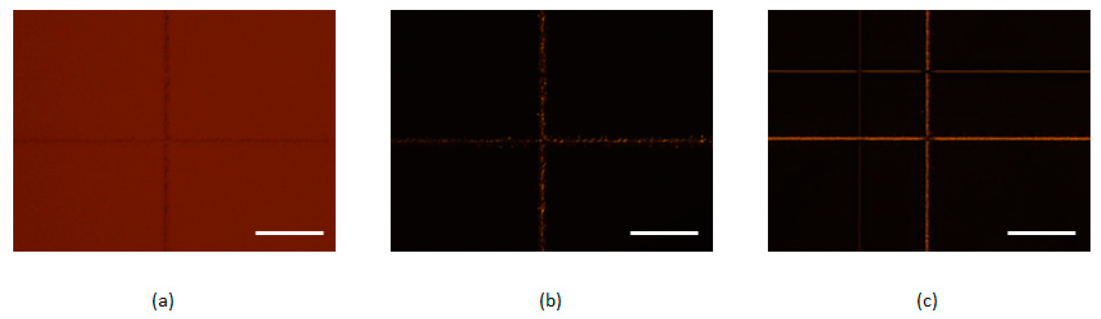
Figure 1a–c respectively shows a bright-field image, a dark-field image, and a phase-contrast image. Refractive index change was barely apparent. However, scattering damage was observed in a bright field image. In contrast, the dark field image revealed microcracks and nonrefractive structural defects of the modification tracks. In this way, the combinational bright field images and dark field images are a promising assessment tool for identifying promising structural modifications in glass. The phase-contrast image enhanced the image contrast of the refractive index change region.
2.2. LED Array Microscope
2.2.1. Optical Setup for an LED Array Microscope
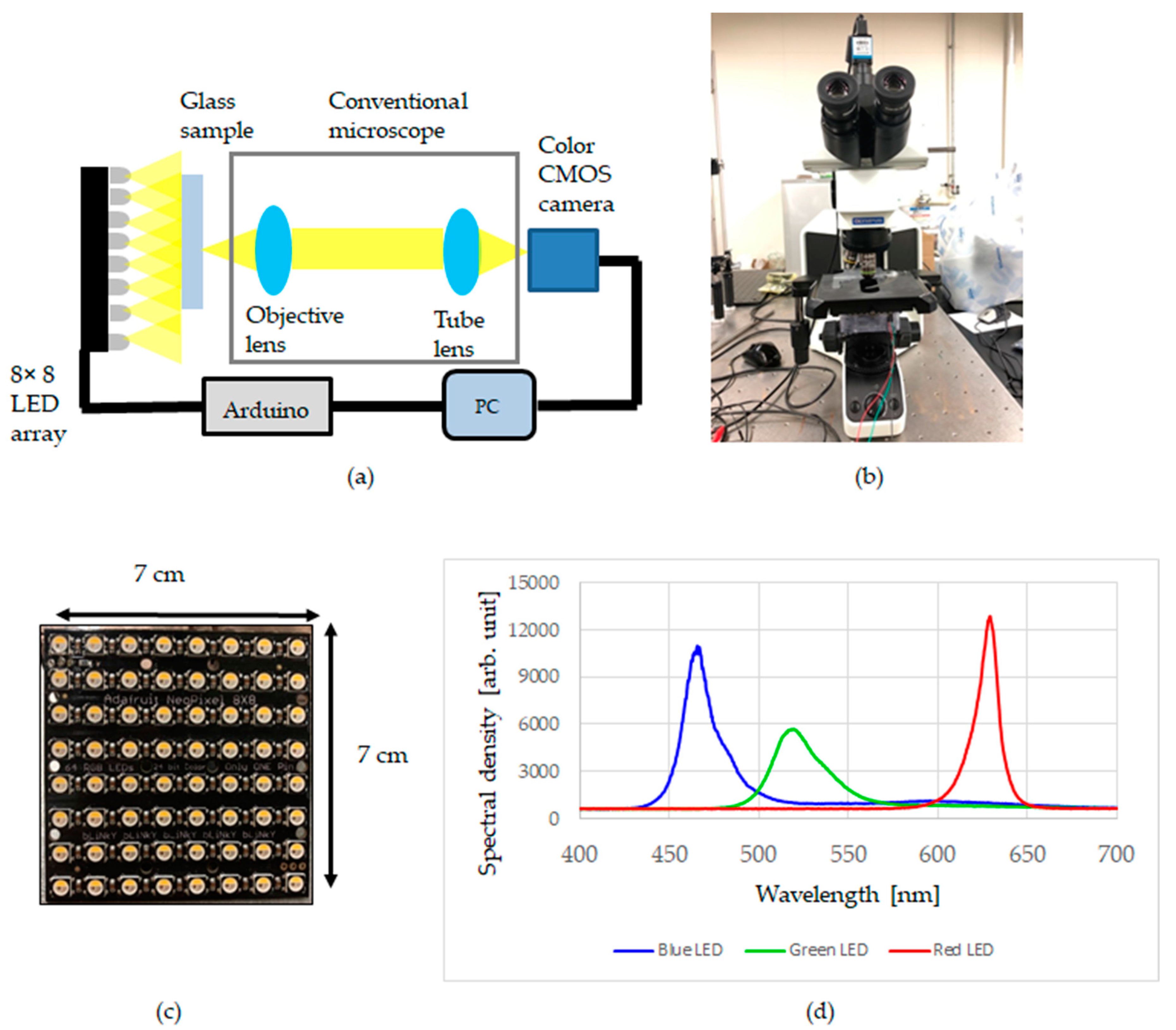
A conceptual diagram of the LED array microscope is presented in Figure 2a. The microscope consists of a part of an upright microscope (BX43; Olympus Corp.). A condenser lens was removed, and an LED array was placed [20]. An RGB full-color dot matrix LED array (8 × 8 dots, NeoPixel NeoMatrix 64 RGBW LED; Adafruit Industries) was placed 35 mm below the sample. The images were captured using a CMOS camera (DFK23UM021; The Imaging Source) through a 10× objective lens with NA of 0.3 (UPlanFLN 10×; Olympus Corp.). The illumination pattern of the LED array was controlled by Arduino. Figure 2b portrays a picture of a constructed LED array microscope. Figure 2c presents an image of the LED array. The LED matrix array size was 7 cm × 7 cm. The pitch between the LEDs was 4 mm. Figure 2d presents spectra of a blue LED, a green LED, and a red LED. The axial resolution was 1.3 μm from the Rayleigh resolution limit, 0.61 λ/NA, where λ is the wavelength of a red LED and NA is the numerical aperture of the objective lens (0.3). The lateral resolution was 4.3 μm from 0.61 λ/NA2.
2.2.2. Multi-Contrast Imaging with an LED Array Microscope
A programmable LED array microscope can provide acquisition of multi-contrast images such as bright-field, dark-field, and DPC images by changing the light source illumination patterns. The bright-field image was taken with a light pattern (Figure 3a), with which a square of central 4 × 4 LED arrays turned on. A dark-field image can be acquired by turning on the LEDs at the array edge (Figure 3b). The DPC images are calculated from sums and differences of two images obtained with the complementary rectangular illumination, as shown in Figure 3c,d. Figure 3c,d respectively present illumination patterns to obtain left–right DPC and top–bottom DPC observation. Images obtained with the left rectangular and the right rectangular are denoted, respectively, as IL and IR. Then, the left–right DPC image, is definable as [18]
Similarly, the top–bottom DPC image, is definable using the illumination in Figure 3d, as
where IT and IB respectively denote images obtained with the top rectangle and the bottom rectangle illuminated. To obtain DPC images using Equation (1) or (2), the images were analyzed using software (Image J).
2.2.3. Rheinberg Illumination with an LED Array Microscope
In Rheinberg illumination, a bright-field image and a dark-field image are obtainable by two-color illumination. Figure 4 presents LED array illumination patterns for Rheinberg illumination. The central rays of light from the LED array pass through a sample and serve as bright-field illumination. Oblique rays from outer ring LEDs hit the sample and serve as dark-field illumination. In Figure 4a, the outer LED array (green LEDs) acts as dark-field illumination. The central LED array (red LEDs) acts as bright field illumination. In Figure 4b, the outer LED array (blue LEDs) acts as dark-field illumination. The central LED array (red LEDs) acts as bright field illumination. Rheinberg illumination can provide both bright-field and dark-field images simultaneously using two-color light sources. After we obtained Rheinberg images, we split the colors of the Rheinberg images into RGB images. Color-coded illumination allows simultaneous acquisition of bright-field and dark-field images of structural modifications in glass at a single shot.
3. Results
3.1. Acquisition of Multi-Contrast Images
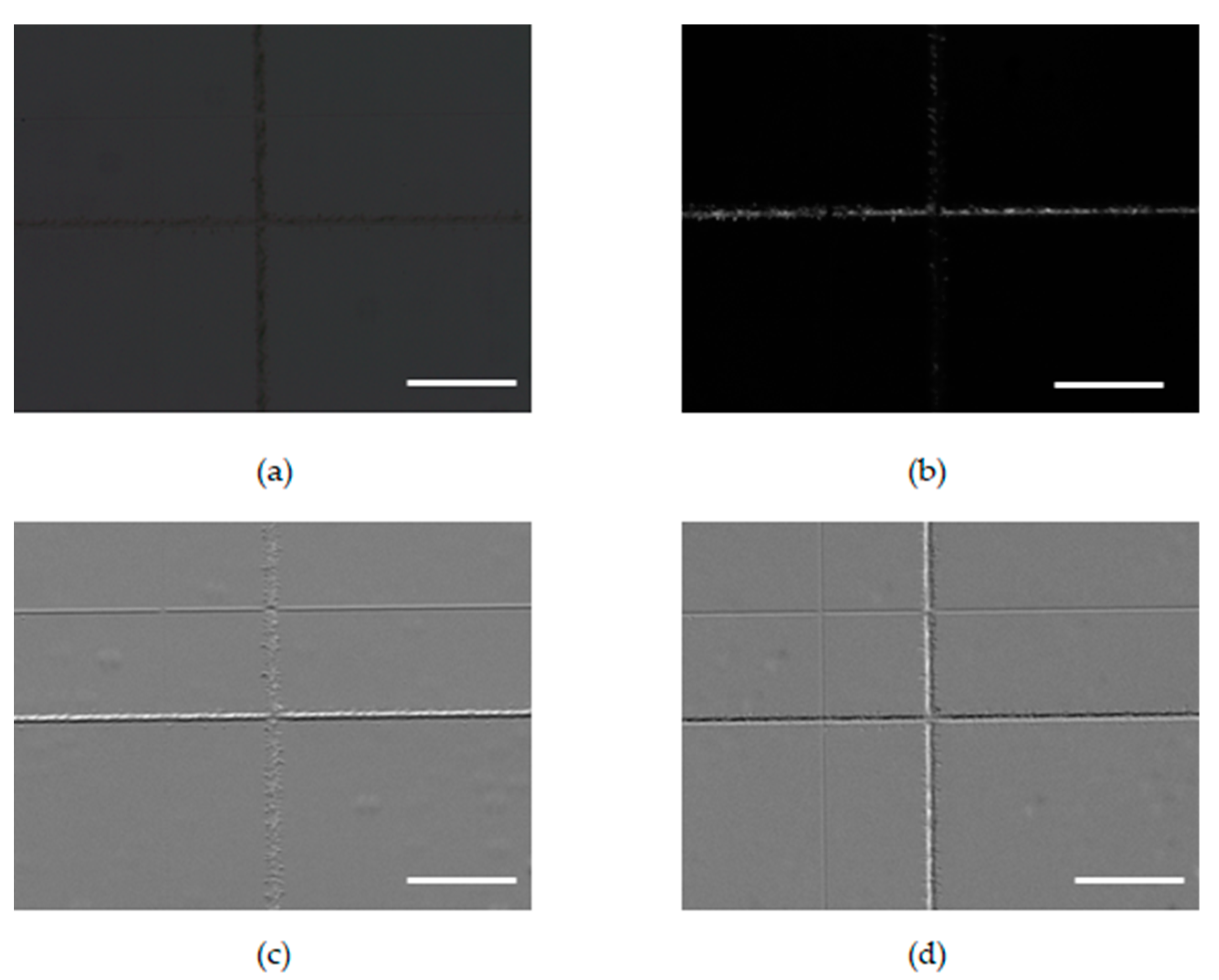
Figure 5 shows various images of the modifications induced inside BK7 glass: (a) bright field image, (b) dark field image, (c) top–bottom DPC image, and (d) left–right DPC image. From the bright field image, the dark field image, and the DPC images, structural changes in the glass were observed by changing the illumination pattern of the LED array. We investigated the contrast of the images. The contrast was calculated using , where and are maximum and minimum intensities in the refractive index region. The values of contrast in the bright field image, top–bottom DPC image, and left–right DPC image were, respectively, 0.08, 0.49, and 0.23. The contrast in DPC was approximately 2.8–6.1 times higher than that in the bright field image. The DPC enhances the contrast of the refractive index change region.
3.2. Simultaneous Acquisition of Bright Field and Dark Field Images by Rheinberg Illumination
Structural changes were observed using Rheinberg illumination. The illumination pattern and color were electrically changed as portrayed in Figure 4a,b. Figure 6 presents Rheinberg images of structural modifications in BK7 and color splitting of Rheinberg images. Figure 6a presents a Rheinberg image of the central red LED array and outer green LED illumination (Figure 4a). We split the colors of the Rheinberg images using Image J software. Figure 6b depicts a red channel after the color splitting of Rheinberg image in Figure 6a. Figure 6c portrays a green channel after color splitting of Rheinberg image in Figure 6a. Based on this result, Rheinberg illumination functions as a bright field for the red part in the center of the LED array and as a dark field for the green part of the outer contour, allowing simultaneous acquisition of bright field images and dark field images of structural changes induced inside the glass.
Figure 6d shows a Rheinberg image of the central red LED array and outer blue LED illumination (Figure 4b). Figure 6e depicts a red channel after the color splitting of the Rheinberg image in Figure 6d. Figure 6f portrays a green channel after color splitting of the Rheinberg image in Figure 6d. The central red LED array acts as bright-field illumination. The outer blue LEDs acted as dark-field illumination. The refractive index change and the scattering damage produced in BK7 glass were identified from the Rheinberg images and computational color splitting of a Rheinberg image.
3.3. Discussion
With conventional microscopes, a mechanical modification is necessary to obtain multi-contrast images. For example, it is necessary to rotate the turret to change the condenser iris and to use a phase difference objective lens for phase difference observation, as presented in Figure 1. However, with an LED array microscope, it is possible to obtain multi-contrast images such as bright-field, dark-field, and DPC images merely by changing the LED lighting pattern. In the refractive index change observed using a bright field image, the contrast was low. In the refractive index change observed using a bright field image, the contrast is low; however, the contrast can be emphasized by DPC. In addition, by Rheinberg images with an LED array microscope, we simultaneously obtained a bright field image and a dark field image.
In conventional microscopes, the phase difference observation is based on the phase-contrast method, so the calculation of images is unnecessary. By contrast, in the LED array microscope, two images are necessary to obtain a DPC image. Moreover, calculation of the image is necessary, because contrast enhancement depends on the illumination direction, only the contrast of the structural change in a specific direction can be emphasized.
Rheinberg illumination microscopy was originally used for visual enhancement of the contrast between a dark-field image and a bright-field image because the bright-field image becomes the background color. For visualization, the combination of green/red or yellow/blue is usually used. When the image is acquired with a color sensor, cross-talk between spectra of RGB LEDs and spectral density of a color sensor is important. Spectral sensitivities in the green channel and red channel in the CMOS sensor are overlapped. Given those circumstances, it is better to use a blue/red channel to reduce cross talk in a dark-field image and a bright-field image.
4. Conclusions
We applied the LED array microscope to visualize femtosecond laser-induced structural modifications. Structural change induced inside BK7 glass using a femtosecond laser was observed using the LED array microscope. We demonstrated bright-field, dark-field, and DPC images of the structural changes using an LED array as a light source and by temporally-changing the illumination pattern. By acquiring the differential phase difference image in the LED array microscope compared to the bright-field image, the contrast of the refractive index change was emphasized. We also demonstrated simultaneous acquisition of bright-field and dark-field images of structural modifications in glass by color-coded Rheinberg illumination and subsequent computational image processing. A programmable RGB LED array allows optical imaging modalities such as bright-field, dark-field, differential phase contrast, and Rheinberg imaging of laser-induced modifications.
Author Contributions
W.W. conceived and designed the experiments. R.S., R.M. and W.W. conducted the experiments. R.S. and W.W analyzed the data. W.W. wrote the manuscript.
Funding
This research received no external funding.
Conflicts of Interest
The authors have no conflict of interest, financial or otherwise, in relation to this study.
References
- Davis, K.M.; Miura, K.; Sugimoto, N.; Hirao, K. Writing waveguides in glass with a femtosecond laser. Opt. Lett. 1996, 21, 1729–1731. [Google Scholar] [CrossRef] [PubMed]
- Itoh, K.; Watanabe, W.; Nolte, S.; Schaffer, C.B. Ultrafast processes for bulk modification of transparent materials. MRS. Bull. 2006, 31, 620–625. [Google Scholar] [CrossRef]
- Gattass, R.R.; Mazur, E. Femtosecond laser micromachining in transparent materials. Nat. Photonics 2008, 2, 219–225. [Google Scholar] [CrossRef]
- Homoelle, D.; Wielandy, S.; Gaeta, A.L.; Borrelli, N.F.; Smith, C. Infrared photosensitivity in silica glasses exposed to femtosecond laser pulses. Opt. Lett. 1999, 24, 1311–1313. [Google Scholar] [CrossRef] [PubMed]
- Chan, J.W.; Huser, T.; Risbud, S.; Krol, D.M. Structural changes in fused silica after exposure to focused femtosecond laser pulses. Opt. Lett. 2001, 26, 1726–1728. [Google Scholar] [CrossRef] [PubMed]
- Will, M.; Nolte, S.; Chichkov, B.N.; Tünnermann, A. Optical properties of waveguides fabricated in fused silica by femtosecond laser pulses. Appl. Opt. 2002, 41, 4360–4364. [Google Scholar] [CrossRef] [PubMed]
- Sudrie, L.; Franco, M.; Prade, B.; Mysyrowicz, A. Writing of permanent birefringent microlayers in bulk fused silica with femtosecond laser pulses. Opt. Commun. 1999, 171, 279–284. [Google Scholar] [CrossRef]
- Shimotsuma, Y.; Kazansky, P.G.; Qiu, J.; Hirao, K. Self-organized nanogratings in glass irradiated by ultrashort light pulses. Phys. Rev. Lett. 2003, 91, 247405. [Google Scholar] [CrossRef] [PubMed]
- Efimov, O.M.; Gabel, K.; Garnov, S.V.; Glebov, L.B.; Grantham, S.; Richardson, M.; Soileau, M.J. Color-center generation in silicate glasses exposed to infrared femtosecond pulses. J. Opt. Soc. Am. B 1998, 15, 193–199. [Google Scholar] [CrossRef]
- Florea, C.; Winick, K.A. Fabrication and characterization of photonic devices directly written in glass using femtosecond laser pulses. J. Lightwave Technol. 2003, 21, 246–253. [Google Scholar] [CrossRef] [Green Version]
- Chen, G.Y.; Piantedosi, F.; Otten, D.; Qiongyue Kang, Y.; Zhang, W.Q.; Zhou, X.; Monro, T.M.; Lancaster, D.G. Femtosecond-laser-written microstructured waveguides in BK7 glass. Sci. Rep. 2018, 8, 10377. [Google Scholar] [CrossRef] [PubMed]
- Mermillod-Blondin, A.; Burakov, I.M.; Stoian, R.; Rosenfeld, A.; Audouard, E.; Bulgakova, N.; Hertel, I.V. Direct observation of femtosecond laser induced modifications in the bulk of fused silica by phase contrast microscopy. J. Laser Micro Nanoeng. 2006, 1, 155–160. [Google Scholar] [CrossRef]
- Mishchik, K.; Ferrer, A.; Ruiz de la Cruz, A.; Mermillod-Blondin, A.; Mauclair, C.; Ouerdane, Y.; Boukenter, A.; Solis, J.; Stoian, R. Photoinscription domains for ultrafast laser writing of refractive index changes in BK7 borosilicate crown optical glass. Opt. Mater. Express 2013, 3, 67–85. [Google Scholar] [CrossRef]
- Samson, E.C.; Blanca, C.M. Dynamic contrast enhancement in widefield microscopy using projector-generated illumination patterns. New J. Phys. 2007, 9, 363. [Google Scholar] [CrossRef]
- Zuo, C.; Sun, J.; Feng, S.; Hua, Y.; Chen, Q. Programmable colored illumination microscopy (PCIM): A practical and flexible optical staining approach for microscopic contrast enhancement. Opt. Lasers Eng. 2016, 78, 35–47. [Google Scholar] [CrossRef]
- Yokoe, R.; Watanabe, W. Multi-contrast imaging of femtosecond-laser-induced modifications in glass by variable illumination with a projector-based microscope. Optik 2017, 150, 48–53. [Google Scholar] [CrossRef]
- Zheng, G.; Kolner, C.; Yang, C. Microscopy refocusing and dark-field imaging using a simple LED array. Opt. Lett. 2011, 36, 3987–3989. [Google Scholar] [CrossRef] [PubMed]
- Tian, L.; Wang, J.; Waller, L. 3D differential phase-contrast microscopy with computational illumination using an LED array. Opt. Lett. 2014, 39, 1326–1329. [Google Scholar] [CrossRef] [PubMed]
- Lee, D.; Ryu, S.; Kim, U.; Jung, D.; Joo, C. Color-coded LED microscopy for multi-contrast and quantitative phase-gradient imaging. Biomed. Opt. Express 2015, 6, 4912. [Google Scholar] [CrossRef] [PubMed]
- Sugimoto, R.; Maruyama, R.; Tamada, Y.; Arimoto, H.; Watanabe, W. Contrast enhancement by oblique illumination microscopy with an LED array. Optik 2019, 183, 92–98. [Google Scholar] [CrossRef]
Figure 1.
(a) Bright-field image, (b) dark-field image, and (c) phase-contrast image acquired with a commercial microscope. Images were obtained with a 10×, NA 0.3 objective lens. Structural modifications were produced in BK7 glass. The femtosecond laser pulses at the energy of 1 Μj/pulse are focused below the surface of 0.1 mm. The sample was translated at a speed of 1 mm/s. The refractive index change was induced at 18.4 μJ/pulse. Scattering damage was produced at 73.6 μJ/pulse. Scale bar: 100 μm.

Figure 2.
(a) Schematic for an LED array microscope. (b) Image of a constructed LED array microscope. (c) Picture of the LED array. (d) Spectra of a blue LED, a green LED, and a red LED.
Figure 2.
(a) Schematic for an LED array microscope. (b) Image of a constructed LED array microscope. (c) Picture of the LED array. (d) Spectra of a blue LED, a green LED, and a red LED.

Figure 3.
Illumination patterns in an LED array to obtain multi-contrast images. Illumination patterns for (a) bright-field, (b) dark-field, (c) left–right differential phase-contrast (DPC), and (d) top–bottom DPC observation.
Figure 3.
Illumination patterns in an LED array to obtain multi-contrast images. Illumination patterns for (a) bright-field, (b) dark-field, (c) left–right differential phase-contrast (DPC), and (d) top–bottom DPC observation.

Figure 4.
Rheinberg illumination patterns in the LED array. (a) A Rheinberg illumination pattern. Outer LED array (green LEDs) acts as dark-field illumination. The central LED array (red LEDs) acts as bright field illumination. (b) A Rheinberg illumination pattern. The outer LED array (blue LEDs) acts as dark-field illumination. The central LED array (red LEDs) acts as bright field illumination.

Figure 5.
Experimental results for structural modifications in BK7 glass: (a) bright field image, (b) dark field image, (c) top–bottom DPC image, and (d) left–right DPC image. Scale bar: 100 μm.
Figure 5.
Experimental results for structural modifications in BK7 glass: (a) bright field image, (b) dark field image, (c) top–bottom DPC image, and (d) left–right DPC image. Scale bar: 100 μm.

Figure 6.
Rheinberg images of structural modifications in BK7 and color splitting of Rheinberg images. (a) Rheinberg images with inner circle/outer illumination: red/green. (b) Red channel after color splitting of Rheinberg image in (a). (c) Green channel after color splitting of Rheinberg image in (a). (d) Rheinberg images with inner circle/outer illumination: red/blue. (e) Red channel after color splitting of Rheinberg image in (d). (f) Blue channel after color splitting of Rheinberg image in (d). Scale bar: 100 μm.

© 2019 by the authors. Licensee MDPI, Basel, Switzerland. This article is an open access article distributed under the terms and conditions of the Creative Commons Attribution (CC BY) license (http://creativecommons.org/licenses/by/4.0/).
Share and Cite
MDPI and ACS Style
Sugimoto, R.; Maruyama, R.; Watanabe, W. Acquisition of Multi-Modal Images of Structural Modifications in Glass with Programmable LED-Array-Based Illumination. Appl. Sci. 2019, 9, 1136. https://doi.org/10.3390/app9061136
AMA Style
Sugimoto R, Maruyama R, Watanabe W. Acquisition of Multi-Modal Images of Structural Modifications in Glass with Programmable LED-Array-Based Illumination. Applied Sciences. 2019; 9(6):1136. https://doi.org/10.3390/app9061136
Chicago/Turabian StyleSugimoto, Ryo, Ryoji Maruyama, and Wataru Watanabe. 2019. "Acquisition of Multi-Modal Images of Structural Modifications in Glass with Programmable LED-Array-Based Illumination" Applied Sciences 9, no. 6: 1136. https://doi.org/10.3390/app9061136
Note that from the first issue of 2016, this journal uses article numbers instead of page numbers. See further details here.