Review of Coal-Fired Electrification and Magnetic Separation Desulfurization Technology

College of Electrical and Power Engineering, Taiyuan University of Technology, Taiyuan 030024, China
*
Author to whom correspondence should be addressed.
Appl. Sci. 2019, 9(6), 1158; https://doi.org/10.3390/app9061158
Submission received: 26 January 2019
/
Revised: 22 February 2019
/
Accepted: 12 March 2019
/
Published: 19 March 2019
(This article belongs to the Section Energy Science and Technology)
Abstract
:This paper briefly introduces various methods of coal desulfurization (physical desulphurization, chemical desulfurization, biological desulfurization, etc.) and analyzes some problems existing in each method. The principle and research process of friction electrostatic separation technology and high gradient magnetic separation technology in pre-combustion desulfurization technology are emphatically introduced, and the development trend of coal-fired desulfurization technology in the future is prospected.
1. Introduction
Coal plays a leading role in the primary energy consumption structure. It is estimated that, by 2020, the total coal consumption in China will still account for 58% of the total energy consumption [1], and the environmental loss per ton of coal will be 185.6 yuan [2] in the course of production and use. According to statistics, in 2015, China’s emissions were 18.59 million tons, and its emissions ranked first in the world, which is the main cause of acid rain, and 90% of SO2 in air pollution is caused by coal burning [3,4]. Relevant research shows that the area covered by acid rain accounts for about 30% of the country’s land area. Therefore, it is of great significance to remove sulfur from coal effectively for the development of economy, the strengthening of environmental protection, the management of serious acid rain problems and the smooth realization of our country’s sustainable development strategy.
This paper consists of the following parts: after the introduction, in Section 2, the form of sulfur in coal is explained; in Section 3, the desulphurization effect of various desulfurization methods is compared, but only the physical desulfurization method in the pre-combustion desulfurization method is used in industry on a large scale; in Section 4 and Section 5, the principles and developments of friction electrostatic separation technology and high gradient magnetic separation (HGMS) technology with broad application prospects are described; in Section 6, the first five sections are summarized, and the future development of coal-fired desulfurization technology is prospected.
2. The Form of Sulfur in Coal
The composition and structure of coal are very complicated. The form of sulfur in coal can be divided into two categories: inorganic sulfur and organic sulfur, as shown in Figure 1 [5].
The presence of inorganic sulfur is mainly disulfide and sulfate. The majority of disulfide sulfur exists in the form of pyrite, and only a small part exists in the form of marcasite, both of them are homogeneous polycrystals, sulfate sulfur exists mainly in the form of gypsum, and relevant data show that inorganic sulfur accounts for 60% to 70% of total sulfur. Organic sulfur exists through forms that combine with the organic structure of coal, for example, mercaptan (-SH), sulfide, disulfide (-S-S-), aromatic cyclic sulfur represented by thiophene system, directly bonded with coal matrix, accounting for about 30–40% of the total sulfur content. In addition, there will be a small amount of elemental sulfur in the coal, PbS, CuFeS2, FeAsS, and ZnS [6,7,8]. Among them, the inorganic sulfur in coal is easier to remove than organic sulfur, and the high sulfur coal in China is generally pyrite, which has a good correlation with ash. Therefore, in the short term, the main direction of our country is still to remove inorganic sulfur from coal.
3. Comparison of Coal-Fired Desulfurization Methods
At present, there are many methods for desulfurization of coal. According to the different desulfurization stages, the coal-fired desulfurization method can be divided into pre-combustion desulfurization, in-combustion desulfurization and post-combustion desulfurization. According to the different media environment, coal-fired desulfurization can be divided into dry desulfurization and wet desulfurization.
The characteristics of pre-combustion desulfurization, in-combustion desulfurization and post-combustion desulfurization are as follows:
1. Pre-combustion desulfurization is mainly achieved by gravity separation, flotation, magnetic separation, electric separation, microwave and jigging technologies to remove sulfur and ash from coal. Pre-combustion desulfurization can not only increase the utilization rate of coal, but also reduce the discharge of ash. It can also greatly reduce the corrosion of sulfur in coal to the equipment in the follow-up process to prolong the service life of the equipment, thus reducing the production cost and reducing the consumption of fuel [5].
2. In-combustion desulfurization mainly refers to briquette sulfur fixation technology and circulating vulcanization bed desulphurization technology, which can remove 50–60% sulfur. It can be seen that the efficiency of this method is not high, and there are problems such as easy slagging, abrasion and blockage in desulfurization process [9].
3. Post-combustion desulfurization, also known as flue gas desulfurization technology, belongs to the end treatment, although the desulfurization rate can be as high as 90%, but its equipment and operation costs are extremely expensive, and secondary treatment of waste liquid problem is prominent, mostly used in America, Japan, Germany and other developed countries [10].
Pre-combustion desulfurization is the source technology of clean coal. It can not only desulphurize and remove ash, but also improve the efficiency of heat energy utilization, and its cost is much lower than that in-combustion desulfurization and post-combustion desulfurization. Therefore, from the perspective of energy saving, green emission and high efficiency, pre-combustion desulfurization is the best choice. According to the principle of desulphurization, pre-combustion desulfurization method can be divided into physical desulfurization, chemical desulphurization and biological desulphurization.
The principle of physical desulphurization is as follows: according to the difference of density, magnetic property, electrical conductivity and floatability of coal and sulfur-containing substances, the inorganic sulfur in coal is removed [11], and this method has been used on a large scale in the current industrial field; the chemical desulfurization method utilizes a chemical reagent such as a strong alkali, a strong acid or a strong oxidant to convert the sulfur in the coal into a liquid or gaseous sulfide by a chemical reaction such as oxidation, reduction or pyrolysis, thus achieving the purpose of desulfurization [12]; the biological desulphurization method is to suspend the coal powder in the suspension containing bacteria, under the action of the desulphurizing bacteria, the sulfur in the coal can be converted into sulphate, thus the purpose of desulfurization can be achieved [13]. Although chemical desulfurization and biological desulphurization can simultaneously remove inorganic and organic sulfur from coal, it is difficult to realize industrialization in the short term due to the complex production process, long production cycle and easy to produce secondary pollution. Therefore, the only real large-scale application in the industrial field is the physical desulphurization method [14]. Table 1 is a summary of some desulphurization methods and desulphurization rates.
The difference between dry desulfurization and wet desulfurization is: the former is carried out in air and the latter in aqueous media such as water/heavy medium suspensions. Wet desulphurization is used earlier and the technology is mature. For a long time, wet desulfurization has been the main method in China’s coal preparation industry. However, the subsequent process needs dehydration, drying and huge coal slurry treatment system, and the investment and operation costs are very high. It is also easy to cause new environmental pollution, which is not conducive to the development of coal enterprises. In addition, considering that most coal-fired power plants use pulverized coal stoves, and that the boiler must be fired with dry powder, and if the wet desulfurization cannot be used to do the online sorting, when the coal block is not sufficiently dissociated and the sulfur in the coal is mostly contaminated by carbon, the effect of using physical desulfurization is very unsatisfactory. Therefore, it is necessary to pulverize the coal to fully dissociate the minerals in the coal and then carry out desulfurization [14].
In pre-combustion desulfurization, friction electrostatic separation and high gradient magnetic separation are the most promising applied technologies in industry at present. Therefore, this paper mainly reviews these two technologies.
4. Friction Electrostatic Separation Technology
4.1. The Basic Principle of Friction Electrostatic Separation Technology
Friction electrostatic separation is based on the difference of mineral electrical properties, under the action of friction and collision, the particles have the opposite electric charge; then, under the action of high voltage electric field, using the difference of electric and mechanical forces acting on these minerals, the movement trajectory of particles is different. The particles are then sorted [15,16].
When charged micro-pulverized coal particles enter the high voltage electric field, they act on the air trailing force, longitudinal drag force, electric field force, gravity and so on, as shown in Figure 2, the trajectory of moving particles in an electric field is described, where x represents the horizontal direction and y represents the vertical direction.
The ratio of the resultant force of the electric field force and the transverse drag force of the air to the mass of the particle is the transverse acceleration of the particle, and the expression is:
where x is the transverse displacement of particles, m; t is the time of particle motion, s; η is the gas viscosity, Pa·s; m is the mass of charged particles, kg; r is charged particle radius (particle is approximately spherical), m; E is the electric field strength, V/m; q is the particle charge, C.
The functional expressions of particle velocity and time can be obtained from Equation (1):
If , the horizontal velocity of particles before leaving the electric field can be expressed as follows:
The ratio of longitudinal air drag force and gravity to particle mass is the longitudinal acceleration of particles, the expression is:
where y is the longitudinal displacement of the particle, m; g is the acceleration of gravity, m/s2.
If the initial condition is t = 0, y (0) = 0, dy (0)/dt = V0, the resistance coefficient of the air resistance of the particles is B = 6πrη/m, the function expressions of displacement and time in the y-axis of particle can be obtained by solving the Equation (4), the expression is:
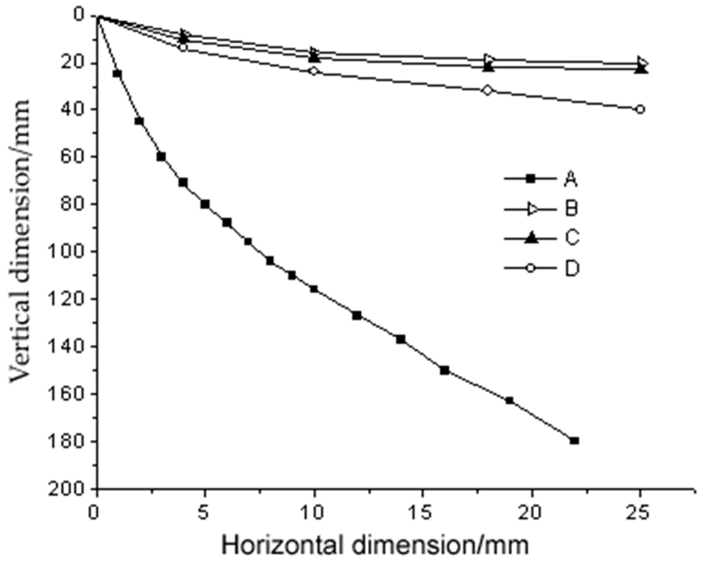
Given the value of B, the trajectory of particles can be obtained from Equations (3) and (5). Under the action of electric force, the negative charge particles with different particle sizes are shifted to the positive plate, and the typical motion trajectory is shown in Figure 3. In this way, it is separated from the positive particles with a negative plate offset, and the separation efficiency of the two kinds of charged particles is higher with the greater difference of the moving trajectories of the two kinds of charged particles [17,18].
4.2. The Development of Friction Electrostatic Separation Technology
Since the emergence of friction electrostatic separation technology, a series of related studies have been carried out both at home and abroad [19,20,21,22,23,24,25,26,27,28,29,30,31,32,33,34,35]. The research on friction electrostatic separation has been active in foreign countries. In the early years, the United States and other countries carried out friction electrostatic separation in the aspects of fly ash decarburization and mineral removal from micro-pulverized coal. However, the domestic start is relatively late, and the research on frictional electrification mainly focuses on the two aspects of pulverized coal treatment and fly ash decarburization.
In the 1970s, the University of Western Ontario [19,20,21] designed a fluidized bed friction charge separator, the device consists of a fluidized bed, a metal screen electrode and a U-type (V-type) collecting tank. In order to overcome the problem that fine ore particles are difficult to fluidize, Kiewiet [20] has carried out an experimental study on the electroseparation of 15–45 μm particles by means of vibratory fluidized bed friction charge method, and a vibratory fluidized bed friction charge separator was developed. The University of Cagliari in Italy has continuously improved the airflow electric separator [22] and redesigned a new type of turbine friction separator. The electrostatic separator overcomes the problem that the fine particles are insufficiently charged due to concentration in the center of the cyclone that they cannot be sorted normally, the low productivity and the high energy consumption. In Germany, Singewald and Fricke invented a method for improving the electrostatic separation of coal powder to remove pyrite [23], in this method, a fatty acid glycerol ester is used to regulate the treatment of pulverized coal and to control the temperature and humidity in the process of electroseparation, after the pulverized coal is treated by this method, a very good sorting effect can be obtained by multi-stage electric selection. After the 1980s, STI (Delaware High-tech Park, Newark, DE, USA), cooperated with NEP, a New England power plant, to install the first prototype of the STI separator with 18 t/h processing capacity at the Salem Port Power Plant of NEP Company [24]. In Canada, the application of rare-phase cyclotron separator in coal separation experiments at the University of Western Ontario, shows that the removal rate of pyrite is 47% [14]. After the 1990s, TAO [25] developed a kind of rotary friction electric separator, which can charge the material particles by the rotating friction charging device. Tao [26] also developed a novel rotary friction separator (RTS) with obvious particle size range. A friction electroseparator was invented by Brown [27] to remove pyrite and ash minerals from pulverized coal. Zhang and Yu studied the electrical properties and triboelectric charge of common associated minerals in coal and coal, the effects of temperature and humidity on the resistivity of coal and its associated minerals are analyzed. It is concluded that increasing the temperature and decreasing the humidity are beneficial to the separation effect [28]. In 2010, Ma analyzed the X-ray fluorescence spectra of four associated minerals and coal sorting products, and concluded that they can be effectively separated by frictional electrification [29]. In 2012, Li and Zhang studied the flow of air and the motion characteristics of particles in the friction electric separator, and found that the air flow movement was greatly disturbed by the friction rod. In addition, the distance between the friction rods has great influence on the airflow and particle, while the spacing of the 20 mm has a better effect on the particle collision, and the distribution of meteorological pressure in friction separator is simulated and analyzed. It is found that the particle small in size has small inertia and a good effect of the following airflow [30,31,32]. Huang [33] conducted a triboelectric selection test of pulverized coal, and carried out single factor tests and orthogonal tests on air volume, voltage and particle size. The study found that there are optimal conditions for the effect of air volume and voltage on sorting. Zhang [34] has applied the innovative rotary friction electroseparator [35] to study the effects of the key operating parameters such as charger speed, separation voltage and airflow velocity on the ash reduction effect of rotary friction electroseparation for micro-pulverized coal.
The main disadvantages of friction electrostatic separation technology for micro-pulverized coal are: poor adaptability to different types of coal, easy to be affected by air humidity and lower upper limit of separation in the separation process. In addition, due to the complexity of charged environment and charged process of coal particles in friction electroseparation equipment, the charged mechanism of particles in many cases has not been fully understood.
5. High Gradient Magnetic Separation Technology
5.1. The Basic Principle of High Gradient Magnetic Separation
The gradient magnetic field of high gradient magnetic separation technology is obtained by filling the magnetic field space with stainless steel wool with high magnetic conductivity, when the pulverized coal passes through the magnetic separator, the paramagnetic particles such as pyrite will be adsorbed on the filled stainless steel wool filter, while the demagnetic coal will pass through the separator smoothly, thus realizing the separation of pyrite and pulverized coal.
The magnetic force Fm of a magnetic particle in a magnetic field can be expressed as follows:
where X is the magnetic susceptibility of a magnetic substance; V is the volume of the particle; H is the magnetic field intensity; and dH/dX is the magnetic field gradient.
Fm = X·V·H·dH/dX,
5.2. The Development of Desulfurization by High Gradient Magnetic Separation
In 1977, Auburn University and Oak Ridge National Laboratory used air entrainment for the first time to conduct dry high gradient magnetic separation tests on several groups of coal in Pennsylvania, 94% inorganic sulfur and 35% ash were removed when the yield of clean coal was 85%. Since then, researchers in Japan, Sweden and the United Kingdom have also conducted similar tests using different high-gradient magnetic separation devices, the results show that: in dry separation of micron grade coal with high gradient magnetic separator, the removal rate of inorganic sulfur is more than 80%, ash content can be reduced by 50–60%, and the recovery of calorific value is more than 90% [37,38,39].
In China, the research on coal magnetic separation desulfurization technology started late, and the research on magnetic separation theory and practice is still relatively weak. Zheng and others from Beijing Campus of China University of Mining and Technology have measured the specific magnetic susceptibility of different kinds of coal and pyrite and minerals in coal, and have carried out an experimental study on coal slurry wet continuous high gradient magnetic separation desulphurization [40,41]. Commissioned by the Jiangsu Provincial Environmental Protection Bureau, Xuzhou Environmental Protection Institute conducted the first experimental study on desulfurization of dry coal powder by magnetic separation in China from 1987 to 1988, the study used periodic high-gradient magnetic separators to conduct small-scale tests in the laboratory. The results show that the magnetic field strength is 0.65–0.75 T, and the desulfurization of 100–120 mesh coal powder can reach up to 70% [42]. In recent years, XCG-II roller magnetic separator has been used in the dry magnetic separation tests of Chazhuang raw coal and Qingdao thermoelectric coal in Qingdao Institute of Architecture and Engineering. For the dry magnetic separation test of Chazhuang coal, the desulphurization rate and ash removal rate are 42.21% and 40.23%, the heat recovery rate is only 57.73%; in the magnetic separation test of Qingdao thermoelectric coal, the desulphurization rate and ash removal rate are 49.10% and 47.88%, respectively, and the yield of clean coal is only 49.88%. This shows that dry magnetic separation of coal powder with XCG-II roller magnetic separator cannot effectively separate organic matter carbon from pyrite and ash forming minerals [43,44]. In 2015, Zhang Bo of China University of Mining and Technology and others used microwave energy to selectively heat pyrite in fine coal to enhance its magnetism. Then, the inorganic sulfur in fine coal (−0.5 mm) was removed using a 2 T strong magnetic roller magnetic separator. Using the microwave energy-intensive method, it was found that the magnetic susceptibility of Weinan and Xiaoyi coals reached the optimum value in 4 min, and the maximum magnetic susceptibility increased by one order of magnitude [45]. In 2017, Zhang et al. studied the complex dielectric constant and loss tangent of fine coal samples from Weinan at microwave frequencies of 0.5–6.5 GHz. It was found that when microwave treatment time was 240 s, the sulfur content of clean coal was as low as 2.92%, the optimum desulfurization degree was 32.01%, and the optimum desulfurization rate was 91.97% [46]. In addition, they studied a new dry separation technology of pulverized coal. Microwave energy was used to enhance the magnetic properties of pyrite and achieve high gradient magnetic separation. The research shows that the restraint conditions of main influencing factors and the optimized indexes of response can be obtained by using a better second-order fitting model, so that the sulfur content of clean coal can be within the range of [1.98, 3.35] [47].
5.3. The Development of High Gradient Magnetic Separators
High gradient magnetic separator is a rapidly developing magnetic separator in recent decades. Since its emergence, scholars at home and abroad have carried out extensive and in-depth research on it.
Domestic and foreign scholars first began to study electromagnetic high gradient magnetic separation equipment. In the late 1960s, Professor Colm of the Massachusetts Institute of Technology Magnet Laboratory used the coil cavity as the separation space, which greatly improved the processing capacity of the unit weight magnetic separation device. A stainless steel magnetic conductive material is used in the magnetic polymer, which makes the magnetic field gradient high in the tiny space and makes the weak magnetic fine particles and even the semi-colloidal particles to be effectively removed. The first high gradient magnetic separation equipment was developed by Professor Colm and the patent of high gradient magnetic separation without iron core [48] was put forward, which opened up a new world of high gradient magnetic separation. For better separation of minerals, MIT, Erize [49] and the IRD company in Britain has done a lot of work on HGMS. The Czech Republic formed a VMS type HGMS on the basis of an MRVK type [50]. The new equipment also includes: charged high gradient, vibration-pulsating HGMS, etc., but the representative is the Sala rotation. In 1989, Maanshan Institute of Mines invented DMG electromagnetic pulsation HGMS. In the 1990s, Changsha Institute developed the CRIMM series of HGMS, which successively produced several non-metal removals for kaolin [51]. In 1998, Guangzhou Nonferrous Metal Research Institute made an SLHG wet vertical ring HGMS [52]. In 2004, it developed SSS-II wet double frequency pulse double vertical ring high efficiency HGMS [53]. In order to improve the efficiency of sorting and solve the blockage of media, the Ganzhou Nonferrous Metallurgy Research Institute has developed a new generation of Slon-type HGMS, which has significantly improved the level of high gradient magnetic separation technology [54]; the Slon-type vertical ring pulsating HGMS [55] has been serialized and Slon HGMS represents the highest level at home and abroad. In 2007, the Institute designed and manufactured Slon-1000 dry vibration HGMS [56].
With the development of science and technology, almost all kinds of magnetic separators are developing towards permanent magnetization. Compared with electromagnetic high gradient magnetic separators, permanent magnet high gradient magnetic separators can save a lot of electric energy, simplify the structure of the equipment and reduce the weight of the machine. The earliest permanent magnet high gradient magnetic separator is a wheeled structure consisting of a vertical ring with a magnetic medium and a permanent magnet. The vertical ring is rotated in the magnetic field generated by the permanent magnet for sorting, using an adjustable horizontal magnetic field and gravity to feed the ore. The result is better in hematite separation [57]. After the rare earth permanent magnet came out, Maanshan Mine Research Institute developed the rare earth permanent magnet high gradient magnetic separator with Nd-Fe-B material. The background magnetic induction intensity can reach 0.6 T, and the separation index can reach the level of the similar electromagnetic high gradient magnetic separator [58]. The Bateman Company in America produces a vertical ring type “iron wheel” type permanent magnet HGMS, and the magnetic magnetic medium is steel wool or metal mesh, which is used for the recovery of tailings fine iron ore from the iron ore rock selection plant [59]. The Eriez company in America developed a Reium100 permanent magnet HGMS, which is the development of “iron wheel” type, field strength is 0.6 T, the magnetic medium is steel plate net, placed vertically, the l2 μm magnetite is separated from 850 μm coal particles, and the recovery of magnetic material is 96–99% [60]. With the development of material science, rare earth permanent magnetic materials have been developed rapidly, which sparked the design of a new permanent magnet high gradient magnetic separator. In 2004, the Changsha Research Institute of Mining and Metallurgy cooperated with the Moscow University of Mining to develop a CRIMM double-box reciprocating permanent magnet high gradient magnetic separator. The machine is equipped with multi-dimensional magnetic separation medium stack in the double sorting box, when entering the magnet, the magnetic induction intensity on the surface of the medium is more than 1.3 T. In 2006, it was applied in the production of iron removal from feldspar, nepheline and kaolinite, and good technical and economic benefits were obtained [61]. In December 2005, Baotou rare Earth Research Institute successfully developed a new type of high gradient, a strong magnetic rare earth permanent magnetic separator. The magnetic separator can raise the grade of iron concentrate by one percentage point compared with the existing equipment, while ensuring that the iron ore recovery rate will not be reduced, and, on the basis of no reduction of concentrate grade, the mineral recovery increased by two percentage points [62].
Superconducting HGMS has become one of the main research directions of HGMS due to its high efficiency and low consumption. Outokumpu and Eriez, two of the top foreign manufacturers, have made many improvements to their original Cryofilter, Powerflux series. The famous manufacturers in recent years are: ACCEL instruments (Alton, CA, USA), GmbH (Frankfurt am Main, Germany), Aguuafine Company (Valencia, CA, USA), Cryomagnetics Company (Oak Ridge, TN, USA), Kyushu Electric Power Company (Fukuoka, Japan) and so on [63]. In China, the research on superconducting high gradient magnetic separation has been carried out by the Beijing Nonferrous Research Institute, but no great progress has been made; only a superconducting HGMS developed by the Institute of Electrical Engineering of the Chinese Academy of Sciences, the diameter of the sorting tank is 0.5 m, the processing capacity is 3 t/h, and the field strength is 3.96 T [64]. In recent years, a new type of high gradient magnetic separator developed by Henan University of Technology has designed a rectangular magnet-tapered magnetic medium system. The optimized taper angle is 60 degrees and the polar distance is 0.005 m, the rotating disc structure is adopted, and the assembling technology of rectangular magnet with the same pole extrusion and different pole interval is adopted in the assembling of magnetic system, which avoids the damage of magnets. Setting an acidic system to strengthen pulverized coal magnetism in order to improve desulfurization rate, the research shows that, when the particle size of Chongqing coal, Gansu coal and Luoyang coal is 0.074 mm, the desulfurization rate of pulverized coal before and after magnetic strengthening increases by 22.77%, 16.93% and 19.99%, respectively [65].
There are some problems in these kinds of high gradient magnetic separators: electromagnetic high gradient magnetic separator uses electromagnets to produce magnetic field, which requires a lot of energy consumption, and also increases the investment and maintenance work of the equipment. Compared with a electromagnetic high gradient magnetic separator, the permanent magnet high gradient magnetic separator has the advantages of low operating cost, high processing capacity, long service life, simple and convenient maintenance; however, it still has the disadvantages that the magnetic structure is unreasonable, the “long beard” phenomenon of the magnetic system internal drainage port and the magnetic pole working surface is not easy to remove, the mechanical inclusions in the sorting process and the blocking of the magnetic medium are obvious. Superconducting high gradient magnetic separators also have fatal disadvantages, such as high investment cost and complex equipment structure. These are important subjects in front of scientific research workers.
6. Conclusions
In the coming decades, coal will still be the most important primary energy source in China. The harmful substances released during the combustion process not only bring serious environmental pollution, but also threaten the life and health of human beings and other organisms. At the same time, it also directly affects the safe and economical operation of the boiler. With the development of economy in our country, the departments concerned pay more and more attention to environmental pollution, so it is necessary to treat coal with desulfurization and ash reduction. The reasonable choice to solve these problems is to reduce the content of sulfur and ash by using the technology of desulfurization and ash reduction before combustion.
Friction electrostatic separation and magnetic separation have great advantages over other technologies, but there are still some defects. For the friction electrostatic separation technology, the problems to be solved in the future are: improving the adaptability of different coal types, weakening the influence of air humidity in the separation process, and raising the separation upper limit, etc. For the magnetic separation technology, the problems to be solved are optimizing the design of magnetic system structure, eliminating the “long beard” phenomenon, avoiding mechanical inclusions and blockage of magnetic concentrator, and further developing a superconducting high gradient magnetic separator. Only by tackling these problems can the application prospects of these technologies be broader.
In the practical application, we must adopt different desulphurization schemes for different coal, deeply study different desulphurization methods, and adopt complementary schemes to take advantage of each other, according to the difference of coal characteristics, to optimize and combine the existing technological process and develop a new process that can maximize desulfurization. It will provide technical support for clean production, high efficiency, economy and reasonable utilization of coal, which has a wide application space, and provides technical support for the realization of coal burning with low smoke and then ultimately achieving a smoke-free state, so as to effectively ensure the ecological environment and social and economic sustainable development.
Author Contributions
Writing—Original Draft: Y.C.; investigation: M.C.; Writing—Review and Editing: C.M.
Funding
This research is supported by the Natural Science Foundation of Shanxi Province (201701D121127) and by the Key Research and Development Program of Shanxi Province (201803D221028-2).
Acknowledgments
Xiaomin Chang provided valuable advice on the study idea and write-up. Thanks also go to Wentao Wu, Xiangnan Hou, Zaihe Shen, Yanzhao Hao, Rui Chen and Jinmeng Wu for their assistance during the research.
Conflicts of Interest
The authors declare no conflict of interest. The founding sponsors had no role in the design of the study; in the collection, analyses, or interpretation of data; in the writing of the manuscript, and in the decision to publish the results.
References
- The National Development and Reform Commission, the State Energy Administration. The 13th Five-Year Plan for the Development of Coal Industry. Development and Transformation of Energy. 2016. Available online: http://www.ndrc.gov.cn/fzgggz/fzgh/ghwb/gjjgh/201706/t20170605_850004.html (accessed on 15 January 2019).
- Wang, J.; Chen, X.; Ning, M. Environmental Challenges and Strategic Countermeasures for Medium and Long Term Energy Development in China. Chin. Eng. Sci. 2011, 13, 2419–2424. [Google Scholar] [CrossRef]
- Ministry of Environmental Protection. Annual Report of Environment Statistics of China (2001–2015). Available online: http://www.cnemc.cn/jcbg/zghjtjnb/ (accessed on 14 March 2019).
- CNTV. Is It Possible for China to Have No Coal? Available online: http://jingji.cntv.cn/2015/01/12/ARTI1421026493565786.shtml (accessed on 14 March 2019).
- Jiao, H.; Ding, L.; Chen, Q. Development and consideration of high gradient magnetic separation desulfurization technology for fine coal. China Min. Ind. 2007, 16, 79–81. [Google Scholar] [CrossRef]
- Jiao, D.; Hu, T.; Jin, H.; Wang, Z.; Zhang, Y. Desulfurization technology and prospect of high sulfur coal. Energy Eng. 2010, 4, 55–58. [Google Scholar] [CrossRef]
- Amir, A.; Corcoran, W.H. Corcoran. Sulfur compounds in coal. Ind. Eng. Chem. Prod. Res. Dev. 1977, 16, 168–170. [Google Scholar] [CrossRef]
- Zhou, C.; Zhou, Z.; Liu, J.; Li, W.; Yuan, L. Application of microorganisms in coal desulfurization. Coal Prep. Technol. 2003, 6, 19–25. [Google Scholar] [CrossRef]
- Zhang, D.; Xie, Q.; Zhang, P.; Zhang, C. Research status of coal desulfurization. Guangxi Light Ind. 2007, 5, 84–85. [Google Scholar] [CrossRef]
- Zuo, W.; Luo, Z.; Wu, W.; Chen, S.; Guo, J.; Liu, X.; Ji, Y. Dry Separation Technology of High sulfur Coal. China Univ. Min. Technol. 2009, 6, 17–21. [Google Scholar] [CrossRef]
- Zhu, F.; Meng, J.; Zhu, S. Application of magnetic separation technology in coal desulfurization. Coal Process. Compr. Util. 2004, 1. [Google Scholar] [CrossRef]
- Ju, C.; Zhang, W.; Li, F. Research progress of coal desulfurization technology at home and abroad. Heilongjiang Sci. 2011, 2, 40–44. [Google Scholar]
- Huang, W.; Zhao, M. Biological desulfurization of coal. Coal Process. Compr. Util. 2014, 5, 70–72. [Google Scholar] [CrossRef]
- Jiao, H.; Cui, J.; Chen, Q. Review on dry desulphurization and ash reduction technology of pulverized coal before combustion. Coal Qual. Technol. 2007, 2, 43–45, 47. [Google Scholar] [CrossRef]
- Yu, H.; Dai, H.; Chen, X.; Yang, W.; He, D.; Jiang, H. Research and development of friction electroseparation abroad. Miner. Prot. Util. 2015, 4, 67–72. [Google Scholar] [CrossRef]
- Xin, D.Z.; Chen, S.L.; Wang, Q.F. Technology of load—Sensitivity used in the hydraulic system of an all—Hydraulic core rig. J. Coal Sci. Eng. 2009, 3, 318–323. [Google Scholar] [CrossRef]
- Tao, D.; Fan, M.; Jiang, X. Dry coal fly ash cleaning using rotary triboelectrostatic separator. Min. Sci. Technol. 2009, 19, 642–647. [Google Scholar] [CrossRef]
- Tao, D.; Al-Hwaiti, M. Beneficiation study of Eshidiya phosphorites using a rotary triboelectrostatic separator. Min. Sci. Technol. 2010, 20, 357–364. [Google Scholar] [CrossRef]
- Inculet, I.I.; Bergougnou, M.A.; Brown, J.D. Electrostatic separation of particles below 40 μm in a dilute phase continuous Loop. IEEE Trans. Ind. Appl. 1977, 13, 370–373. [Google Scholar] [CrossRef]
- Kiewiet, C.W.; Bergougnou, M.A.; Brown, J.D.; Inculet, I.I. Electrostatic separation of fine particles in vibrated fluidized beds. IEEE Trans. Ind. Appl. 1978, 14, 526–530. [Google Scholar] [CrossRef]
- Beeckmans, J.M.; Inculet, I.I.; Dumas, G. Enhancement in segregation of a mixed powder in a fluidized bed in the presence of an electrostatic field. Powder Technol. 1979, 24, 267–269. [Google Scholar] [CrossRef]
- Alfano, G.; Liu, Y.; Yang, Y. Progress of triboelectric separation of minerals. Ore Dress. Foreign Metals 1989, 2, 1–9. [Google Scholar]
- Singewald, A.; Fricke, G. Process for Electrostatic Separation of Pyrite from Crude Coal. U.S. Patent 3,941,685, 2 March 1976. [Google Scholar]
- Huang, K. Separation of Unburned Carbon from Fly Ash. Foreign Miner. Process. KuaiBao 1997, 19, 6–8. [Google Scholar]
- Tao, D. Electrostatic Particle Separation Device. Patent 200420079562.1, 14 December 2005. [Google Scholar]
- Tao, D.; Sobhy, A.; Li, Q.; Zhao, Y. Dry cleaning of pulverized coal using a novel rotary triboelectrostatic separator (RTS). Int. J. Coal Prep. Util. 2011, 31, 187–202. [Google Scholar] [CrossRef]
- Brown, D.K. Electrostatic Pyrite Ash and Toxic Mineral Separator. U.S. Patent 5637122, 10 June 1997. [Google Scholar]
- Zhang, X.; Duan, C.; Yu, F.; Gao, M.; He, J. Study on Electrical Properties and friction electrification of pulverized Coal. J. China Univ. Min. Technol. 2005, 34, 694–697. [Google Scholar] [CrossRef]
- Ma, R.; Shi, C.; Zhang, X. Separation of coal from single mineral in triboelectric separation. J. China Univ. Min. Technol. 2010, 39, 270–274. [Google Scholar]
- Li, H.; Zhang, X.; Chen, Y.; Chen, M.; Chen, F. Numerical simulation of gas-solid two-phase flow field in fly ash electric separation and decarburization friction device. Coal Technol. 2012, 31, 140–142. [Google Scholar] [CrossRef]
- Li, H.; Zhang, X.; Chen, Y.; Chen, M.; Chen, F. Study on gas flow and single particle motion characteristics of electric friction separator. Coal Prep. Technol. 2012, 3, 2219–2240. [Google Scholar] [CrossRef]
- Li, H.; Zhang, X.; Chen, Y. Characteristics of collision of particles in frictional electroelector. J. China Univ. Min. Technol. 2012, 41, 607–612. [Google Scholar]
- Huang, G.; Luo, S.; Zhou, Y.; Ma, Y.; Yi, Y. Triboelectric separation of pulverized coal. Coal Technol. 2015, 34, 315–317. [Google Scholar] [CrossRef]
- Zhang, W.C.; Tao, Y.; Song, A.; Xian, Y.S.; Man, Z.P.; Xue, Y.W. Experimental study on dust reduction by rotating friction electric separation of micro-pulverized coal. Coal Sci. Technol. 2017, 45, 196–200. [Google Scholar] [CrossRef]
- Chen, B.; Yang, G.; Gao, J. Modeling and simulation of gas-liquid hydraulic impactor based on AMESim. J. Shanghai Univ. Eng. Technol. 2011, 25, 292–295. [Google Scholar] [CrossRef]
- Wang, C. Mechanism and Research status of Coal Desulfurization by Magnetic Separation. Qual. Saf. 2014, 26, 219, 221. [Google Scholar] [CrossRef]
- Kelland, D.R.; Lai-Fook, M.; Maxwell, E.; Takayasu, M.; Jacobs, I.S.; McConnel, M.D. HGMS coal desulfurization with microwave magnetization enhancement. IEEE Trans. Magn. 1988, 24, 2434–2436. [Google Scholar] [CrossRef]
- Hise, E.C.; Holman, A.S.; Friedlaender, F.J. Development of high-gradient and open-gradient magnet separation of dry fine coal. IEEE Trans. Magn. 1981, MAG-17, 3314–3316. [Google Scholar] [CrossRef]
- Fine, H.A.; Lowry, M.; Power, L.F.; Geiger, G.H. A proposed process for the finely divided coal by flash roasting and magnetic separation. IEEE Trans. Magn. 1976, MAG-12, 523–527. [Google Scholar] [CrossRef]
- Tang, Y.; Yam, D.; Zheng, J.; Guo, M.; Rong, X.; Ni, Y. Magnetic properties and mechanism of pyrite in coal. Sci. Bull. 1995, 40, 1483–1486. [Google Scholar]
- Zheng, J. Fine Coal Desulphurization Study on Magnetic Susceptibility of Coal and Associated Minerals and Desulfurization of High Gradient Magnetic Separation Coal. Ph.D. Thesis, China University of Mining and Technology, Beijing, China, 1993. [Google Scholar]
- Wu, S.; Zhang, H.; Zhang, S. Experimental study on Desulfurization of dry pulverized Coal by Magnetic Separation. Environ. Sci. 1989, 11, 25–28. [Google Scholar] [CrossRef]
- Zhu, F.; Zhu, S. Experimental study on desulfurization and deashing of coal-fired high gradient magnetic separation. Coal Sci. Technol. 2005, 33, 61–68. [Google Scholar] [CrossRef]
- Wang, D.; Li, Y. Experimental study on Desulfurization by High gradient Magnetic Separation. Shandong Electr. Power Technol. 2004, 3, 7–11. [Google Scholar] [CrossRef]
- Zhang, B.; Zhao, Y.; Zhou, C.; Duan, C. Fine Coal Desulfurization by Magnetic Separation and the Behavior of Sulfur Component Response in Microwave Energy Pretreatment. Energy Fuels 2015, 29, 1243–1248. [Google Scholar] [CrossRef]
- Zhang, B.; Fan, X.; Zhao, Y.; Cai, L. Desulfurization of microwave pretreated fine coal by magnetic separation. Part. Sci. Technol. 2018, 36, 600–608. [Google Scholar] [CrossRef]
- Zhang, B.; Zhu, G.; Sun, Z.; Yan, G.; Yao, H. Fine coal desulfurization and modeling based on high-gradient magnetic separation by microwave energy. Fuel 2018, 217, 434–443. [Google Scholar] [CrossRef]
- Yan, Y.; Deng, S.; Zhou, W.; Lin, M. Research and application of magnetic separation technology for coal desulfurization. Environ. Prot. Coal Mines 1999, 13, 17. [Google Scholar] [CrossRef]
- Whitesides, G.M.; Romas, J.K.; Josephson, L. Magnetic separation in biotechnology. Trends Biotechnol. 1983, 11, l44–148. [Google Scholar] [CrossRef]
- Sun, Z. Development of permanent magnets and some magnetic separators. Metal Mine 2006, 8, 52–59. [Google Scholar]
- Li, X.; Xu, X.; Zhou, Y.; Wang, M. The role of CRMM High gradient Magnetic Separator in Kaolin Refining. Miner. Prot. Util. 2005, 6, 25–27. [Google Scholar] [CrossRef]
- Tang, Y. Development and Application of Wet Vertical Ring High Gradient Magnetic Separator. In Proceedings of the Fourth National Academic Conference of Mineral Processing Equipment, Kunming, China, 1 September 2001. [Google Scholar]
- Tang, Y. Development of SSS-II wet double frequency double vertical ring high gradient magnetic separator. Metal Mines 2004, 333, 37–39. [Google Scholar] [CrossRef]
- Xiong, D.; Liu, J. New Progress of Slon pulsation and Vibration High gradient Magnetic Separator. Metal Mine 2006, 361, 4–7. [Google Scholar] [CrossRef]
- Yi, D. Application of Vertical Ring pulsating High gradient Magnetic Separator in Meishan Iron Mine. Des. Constr. Metall. Mines 1999, 2, 35–39. [Google Scholar] [CrossRef]
- Liu, X.; Chen, J. Development of a new Slon- 1000 dry vibration high gradient magnetic separator. Nonmet. Ores 2006, 29, 32–34. [Google Scholar] [CrossRef]
- Luo, Z. Summary of Papers of the Fifteenth International Concentration Conference (Gravity and Magnetic Separation). Yunnan Metallurgy 1987, 4, 20–24, 32. [Google Scholar]
- Wu, S.; Wu, Z.; Shen, H.; Wei, J.; Zhao, G.; Wu, F.; Yu, H. Current Situation and Development Direction of Magnetic Separation Equipment in China. In Proceedings of the National New Beneficiation Technology and Its Development Direction of Academic Research and Technology Exchange, Hainan, China, 1 October 2004. [Google Scholar]
- Feng, D.; Sun, Z. Application of NdFeB Permanent Magnet in Mineral Processing. Magn. Mater. Devices 1994, 25, 51–55. [Google Scholar]
- Feng, D.; Sun, Z. The present situation and Progress of permanent Magnet Separator. Ore Dress. Foreign Metals 1992, 12, 1–5. [Google Scholar]
- Li, X.; Zhou, Y.; Cao, C. Development and Application of CRIMM double-box reciprocating permanent Magnet High gradient Magnetic Separator. Metal Mine 2008, 1, 47–48. [Google Scholar] [CrossRef]
- Cheng, B. Identification of two subjects in Baotou rare Earth Research Institute. Rare Earth 2006, 2, 56. [Google Scholar] [CrossRef]
- Harris, P. Pulling power of Eriez Magnetics. Ind. Miner. 2002, 416, 60–62. [Google Scholar]
- Sun, X. Review of superconducting magnetic separation. In Proceedings of the 9th Conference National Annual Review of Mineral Collected Non-Ferrous Metals, Xiamen, Fujian, 1 November 2001. [Google Scholar]
- Kai, Y. The High Gradient Magnetic Separation Desulfurization Experiment Study of Pulverized Coal Combustion Based on Enhanced Acid. Master’s Thesis, Henan University of Technology, Zhengzhou, China, 2017. [Google Scholar]
Figure 1.
Distribution of sulfur in coal.

Figure 2.
The trajectory of particles in an electric field.
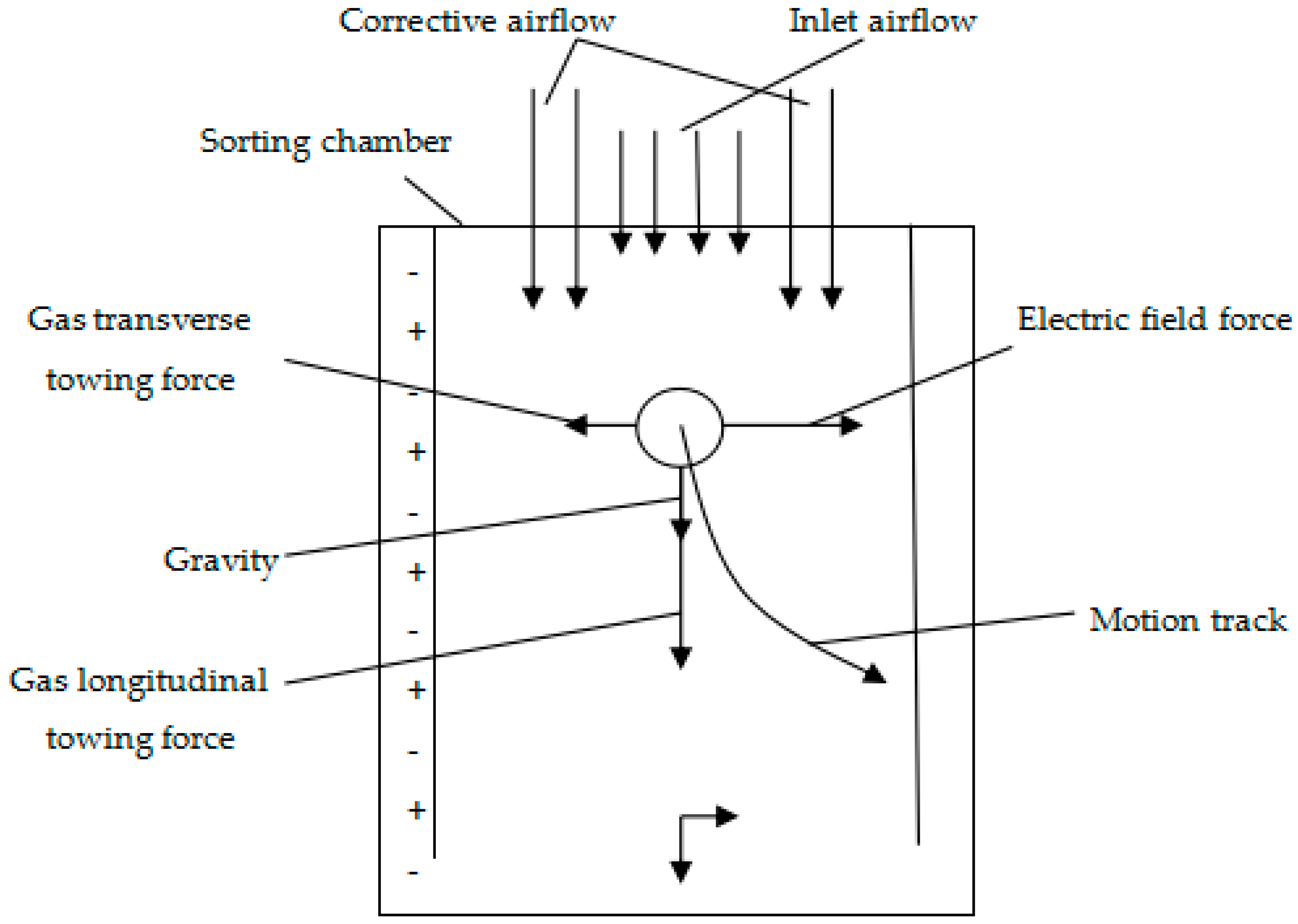
Figure 3.
Motion trajectories of negatively charged particles with different particle sizes in an electric field [17,18]. A, B, C and D represent 44 μm, 106 μm, 209 μm, 400 μm particals respectively.

Table 1.
Summary of partial desulfurization methods and desulphurization rates.
| Method Name | Fundamental | Removal of Pyrite/% | Removal of Organic Sulfur/% | |
|---|---|---|---|---|
| Physical desulphurization method | Gravity method | Coal and pyrite have density difference | 40–70 | 0 |
| Flotation method | Coal is hydrophobic, pyrite is hydrophilic | 53 | 0 | |
| Magnetic separation method | Pyrite has weak magnetism | 60–80 | 0 | |
| Friction electrical separation method | Coal and pyrite are electrically different | 50–80 | 0 | |
| Chemical desulfurization method | BHC (benzenehexachloride) method | Alkali aqueous solution method | 50–84 | 0 |
| Microwave method | Microwave energy | 10–40 | 10–30 | |
| High energy radiation method | Radiation forming free radical and oxidation | 30–80 | 10–70 | |
| Chlorine decomposition method | Cl2 decomposition | >90 | 70 | |
| Biochemical method | Biological oxidation–reduction | 60–90 | 50–60 |
Table 2.
Specific magnetic susceptibility of major minerals in coal.
| Component | Specific Magnetic Susceptibility ×10−9/kg·m−3 |
|---|---|
| Pyrite | 3.4 |
| Pyrrhotite | Strong magnetism |
| Limonite | 700 |
| Siderite | 4000 |
| Iron silicate | 1260 |
| Calcite | 12.0 |
| Clay | 250–490 |
| Shale | 490–570 |
| Sandstone | 180–250 |
| Coal | −5.0 |
© 2019 by the authors. Licensee MDPI, Basel, Switzerland. This article is an open access article distributed under the terms and conditions of the Creative Commons Attribution (CC BY) license (http://creativecommons.org/licenses/by/4.0/).
Share and Cite
MDPI and ACS Style
Chen, Y.; Cao, M.; Ma, C. Review of Coal-Fired Electrification and Magnetic Separation Desulfurization Technology. Appl. Sci. 2019, 9, 1158. https://doi.org/10.3390/app9061158
AMA Style
Chen Y, Cao M, Ma C. Review of Coal-Fired Electrification and Magnetic Separation Desulfurization Technology. Applied Sciences. 2019; 9(6):1158. https://doi.org/10.3390/app9061158
Chicago/Turabian StyleChen, Yan, Min Cao, and Chunyan Ma. 2019. "Review of Coal-Fired Electrification and Magnetic Separation Desulfurization Technology" Applied Sciences 9, no. 6: 1158. https://doi.org/10.3390/app9061158
Note that from the first issue of 2016, this journal uses article numbers instead of page numbers. See further details here.