Helicopter Rotor Thickness Noise Control Using Unsteady Force Excitation

National Key Laboratory of Rotorcraft Aeromechanics, Nanjing University of Aeronautics and Astronautics, Nanjing 210016, China
*
Author to whom correspondence should be addressed.
Appl. Sci. 2019, 9(7), 1351; https://doi.org/10.3390/app9071351
Submission received: 13 January 2019
/
Revised: 27 March 2019
/
Accepted: 28 March 2019
/
Published: 30 March 2019
(This article belongs to the Special Issue Active and Passive Noise Control)
Abstract
:The low-frequency in-plane thickness noise generating from the displacement of air by rotating blades has an important influence on helicopter detection. An on-blade control technique to reduce thickness noise is developed in this paper based on the principle of sound field cancellation. Following the theoretical study on the mechanism of thickness noise reduction using in-plane unsteady force, a 2-m diameter rotor with an active trailing-edge winglet are designed and tested in a fully anechoic chamber. The winglet installed on the outboard blade is used to generate the unsteady force and anti-noise to counteract the thickness noise. The results demonstrate that effective reduction of thickness noise up to 3 dB is achieved in the front of the rotor when the winglet is under the one-harmonic control with of deflection angle. Moreover, the experiments of frequency, amplitude, and phase scanning are carried out to study the parametric effects of winglet motions on noise reduction. The ability of noise reduction is proportional to the deflection amplitude of the winglet in each frequency. The control phase determines where noise can be reduced. There is an optimal phase angle at each frequency to minimize the noise at the observations, and it varies with different frequencies. The relationship among observation position, control phase, and frequency is derived, and the approximate expression of the optimal phase is presented.
1. Introduction
With the wide application of helicopters in military and civilian fields, serious problems concerning noise radiation have been brought to the forefront, emerging as a major factor to be considered in helicopter design. Rotor noise is the main noise source produced by a helicopter and can be classified into thickness, loading, blade-vortex interaction, and high speed impulsive (HSI) noise [1]. Among them, the rotor thickness noise, which features low frequency, slow attenuation, and far-distance propagation, mainly spreads outward along the rotor disk plane. It is the major composition of helicopter far-field noise and a primary sound detection subject. Consequently, it is of great significance to explore a control method that can effectively reduce the in-plane thickness noise.
Noise reduction can be achieved through passive means such as reduction of rotor rotational speed and blade tip design. Although reducing the rotational speed is of great benefit to noise, it also has significantly adverse impacts on vibration and safety. Therefore, most studies focus on noise reduction by altering the blade tip. Baeder et al. [2] conducted a parametric study to investigate the effects of sweep, taper, and thinning on the in-plane rotor noise. Results indicated that at moderate tip Mach numbers, thinning and tapered blade tips are more effective for reducing the thickness noise, while at high tip Mach numbers, swept blade tip is more effective for reducing high speed impulsive noise. Chae et al. [3] carried out the rotor shape optimization for improving aeroacoustic performance, including the effects of taper ratios, sweep back, tip chord length, protrusion shape, camber, and airfoil. Edwards et al. [4] designed a low-noise rotor for a moderate-weight helicopter by including the reduced noise features of modulated blade spacing and swept ogee tip shape. In reference [5], Yung discusses a series of rotor tips for blade-vortex noise reduction. Barakos et al. [6] used the multi-block computational fluid dynamics (CFD) to study the effect of anhedral tip on blade noise. Nowadays, some passive noise reduction techniques are being applied to the design of new generation helicopter rotors [7].
However, the passive design also affects the rotor performance because compromises should be made between noise reduction and performance improvement, and adaptation to different flight conditions should also be taken into consideration. The active control is a more attractive way to reduce rotor noise. Active rotor control has been studied for several years, but most studies were for blade-vortex interaction (BVI) noise. It can be achieved through higher harmonic control [8,9,10], individual blade control [11,12,13], active flaps [14,15,16,17], and active twist [18,19,20]. The numerical and test results demonstrate that the active rotors are effective for BVI noise and vibration reduction as well as performance enhancement. However, the research on active control for thickness noise reduction is very limited. Gopalan et al. [21,22] and Sim [23] separately proposed the novel control method for reducing the in-plane noise of the rotor disc in the principle of noise field cancelation and compared the noise reduction effect of single monopole and dipole sources as well as multiple controllers. Yang et al. [24] studied the relation between the loading solution and resulting noise and proposed two active devices for in-plane noise reduction. Some experimental studies on thickness noise reduction have been carried out as well. Sim et al. [25] conducted an experiment in a wind tunnel test using the Boeing-SMART rotor with active flaps and demonstrated that with the active flap, it is possible to reduce in-plane noise. They also analyzed the noise reduction mechanism that causes the active flap to alter the blade torsion and change the local angle of attack and lift, which is responsible for the generation of in-plane force needed for the noise reduction at the target observer. Sargent [26] studied the noise generation mechanism of the tip blowing control and conducted noise tests. The results showed that the in-plane noise of target observation points in the rotor disk plane can be reduced by using on-blade, tip air blowing control.
In this paper, a noise reduction technique for the rotor thickness noise using a force actuator on the blade tip is developed and verified. Firstly, the theoretical analysis on the formation of rotor noise and the mechanism of noise reduction through force excitation was performed. Then, a 2-m diameter model rotor with an active trailing edge winglet was designed, which was used to generate high-frequency unsteady control force. Through the results of the open-loop test (frequency, phase, and amplitude scanning) in a rotor anechoic chamber, the effectiveness of the unsteady force excitation on thickness noise reduction was analyzed, as well as the influence of control parameters of the winglet.
2. Principle of Thickness Noise Reduction
In theoretical study, the formulation F1A [27], an integral form of the FW-H equation, is employed for noise prediction. The noise prediction solver was validated in reference [28], thus only a brief description is given here. The acoustic pressure in the F1A formulation can be expressed as a summation of thickness noise and loading noise :
where,
are density and sound speed in undisturbed air, is the local normal velocity of blade surface, is the length of the radiation vector, is the sectional Mach number, and is the force on the blade surface. The subscript denotes the radiation direction (e.g., ). The superscript denotes the rate of variation with respect to the source time. The subscript ret indicates that the integrals are evaluated at the retarded time. The terms with are inversely proportional to the square of distance and can be neglected when the observer is far away from the rotor. Then, Equations (2) and (3) can be rewritten as:
The principle of thickness noise reduction can be explained by the above two equations. To achieve it, a 2-m diameter model rotor was used to conduct analytical research. The rotor parameters and operation conditions are given in Section 3.1.
The rotor thickness noise is caused by the periodic displacement of air produced by blades rotating. According to Equation (4), the sound pressure comes from the contributions of oscillation of airflow velocity (velocity term) and its time derivative (time derivative term). Figure 1 shows the time histories of overall sound pressure and contributions from two terms at a far-field observation position (100 times radius). The positive sound pressure waveform is generated by velocity term, while the negative pressure, which determines the main waveform feature of the thickness noise, is caused by the time derivative term.
Equation (5) governs the noise generated from air-load and has consistent form with thickness noise Equation (4). Through adjusting the amplitude and direction of force, the thickness noise can be partly canceled. This is the theoretical foundation of the concept of sound cancelation control. In this paper, a thickness noise control method was developed based on the unsteady on-blade force. As shown in Figure 2, the unsteady aerodynamic force was arranged at the outer portion of the blade to excite a controllable sound wave (anti-noise) opposite to the original noise (thickness noise). The superposition of them could cancel the sound pressure in a certain area, thereby reducing noise. The thickness noise radiated along the rotor plane and decreased gradually out of plane (as seen in Figure 1). According to the propagation directivity of the force-generated noise, an unsteady force parallel to the rotor plane is required to generate the in-plane anti-noise.
Although exciting force works in several forms, considering achievability, this paper explores the exciting force in harmonic wave: , in which is the amplitude, is the harmonic, and , are the azimuthal angle and the initial exciting angle, respectively. Figure 3 shows the calculated time history of the anti-noise pressure generated by the exciting force with . The sound pressure waveform is composed of two parts, and the positive pulse generated by the time derivative of force is dominant, which can be used to cancel the negative sound pressure of the thickness noise. The negative waveform is caused by the exciting force and can cancel the positive portion of the thickness noise. The parameters governing the anti-noise properties include the magnitude, initial phase angle, and frequency of exciting force.
Figure 4 shows the effect of force amplitude on noise reduction. When the amplitude of the exciting force increases, the positive pulse of anti-noise increases, and the sound pressure is reduced. However, the overall noise will increase if a large force is exerted. Thus, the proper exciting force should be designed to satisfy the requirement in practical applications. In Figure 5, the effect of excitation frequency on noise reduction is analyzed. Three frequency harmonics changed from n = 1 to 3 with . It is seen that high frequency increased the time rate of force and the resultant anti-noise peak, thus more noise reduction was achieved. However, further increasing had an adverse influence similar to the effect of force amplitude.
3. Validation of Noise Reduction Method
3.1. Model Rotor and Test System
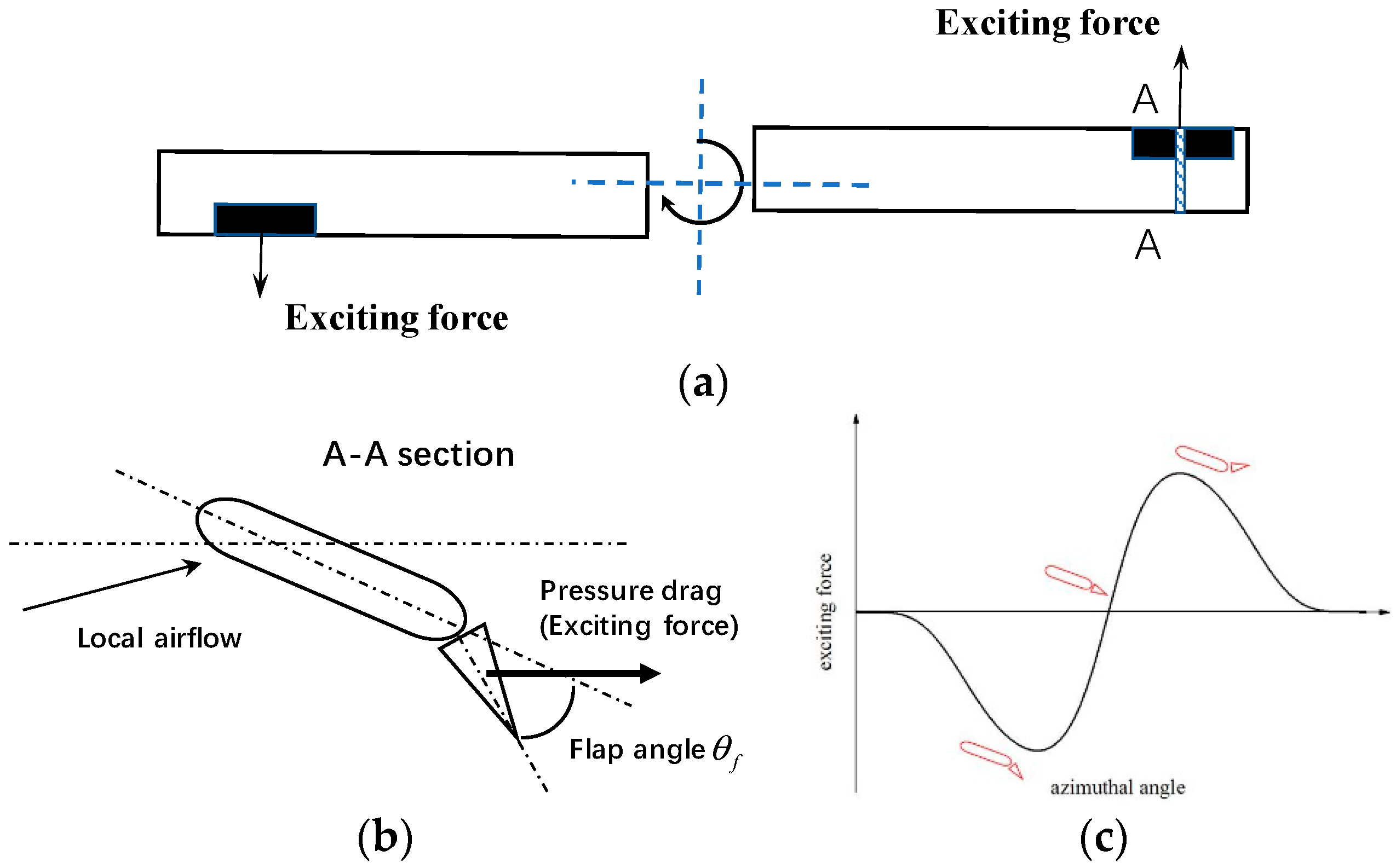
Due to the complex flow environment around the helicopter rotor tip, it is important to generate an unsteady exciting force at the tip of the blade while having little influence on aerodynamic performance. In this paper, a model rotor with a trailing-edge winglet was designed to verify the principle of the sound field cancelation. As shown in Figure 6, an active winglet was installed at the trailing edge of the blade tip, and when it deflected, a change in the windward area caused a variation of pressure drag, thereby forming the required unsteady force in the rotor plane. The deflection law of the winglet is , where represents the winglet deflection angle, is the deflection amplitude, is the frequency harmonic, is the initial phase angle, and is the azimuthal angle.
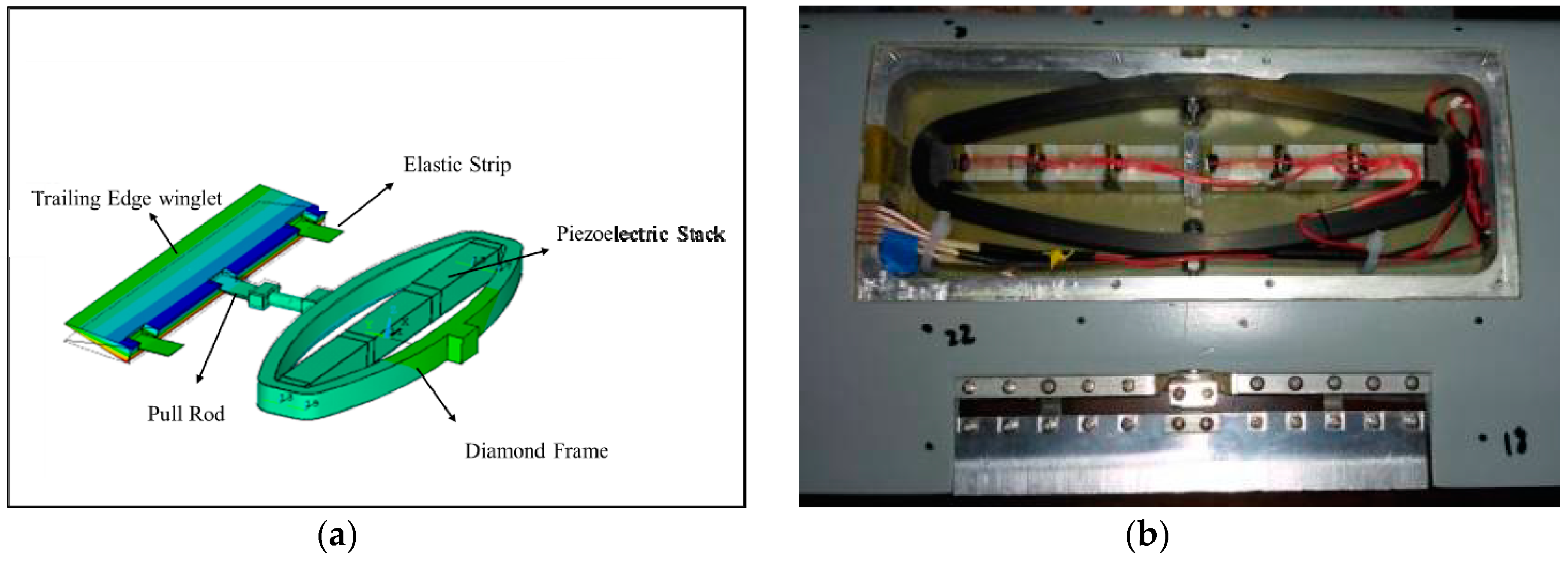
Figure 7 shows the model rotor used in the experiment. The airfoil was OA212, the radius R was 1.27 m, the chord c was 0.13 m, and the linear twist was −8° (from blade root to tip). The trailing-edge winglet had a length of 0.118 m, and the chord was 0.02 m. The winglet was driven by a drive mechanism embedded in the outboard blade to achieve high-frequency rotation in a strong centrifugal force field. In addition, the quality of the drive mechanism was required to be light. The drive mechanism designed in this paper combined the piezoelectric stack and the diamond-shaped amplifier, as shown in Figure 8. When an alternating voltage was applied to the piezoelectric stack, a telescopic motion occurred, which was amplified by the diamond-shaped frame to generate a slight displacement, which was converted into a push-pull motion of the pull rod. Then, the winglet achieved deflection by the bending deformation of the elastic piece.
The measurement in the non-rotating condition showed that the amplitude of the winglet deflection angle was of linear dependence to the voltage on the piezoelectric stack, and about 0.8° corresponded to 10 V voltage change. In the rotating condition, the deflection amplitude was affected by the aerodynamic force and centrifugal force acting on its surface. Due to the lack of angular displacement feedback control in our small-scale rotor model, the deflection angle could not be adjusted in real time, thus there may have been some differences between rotation and non-rotation conditions. This is one of the limitations of present test facilities. To minimize this adverse effect, a lightweight winglet (about 15 g) and a high-power piezoelectric reactor driver were used in the test. The required power of the active winglet can be estimated from , where is deflection frequency, is capacitance of piezoelectric stack, and is voltage.
Taking the maximum power state in the present test as an example (the test cases are seen in Section 3.2), the required power was . The rated output power of the piezoelectric reactor was 300W, and it could provide sufficient power, even in the flap in the rotation environment. Therefore, the relationship between the deflection amplitude and voltage in a rotating condition is similar to the non-rotation state.
Figure 9 shows the schematic diagram of the test control system. A sinusoidal analogue signal was emitted from the controller when it received the pulse signals from the host computer and the rotor. Then, the signal was amplified by the power amplifier to output alternating voltages to drive the mechanism of the trailing-edge winglet through the current collecting ring of the rotor test rig. The data acquisition system collected the noise signals of the microphones and the vibration signals of the balances. The capabilities of the test facilities well satisfied the requirement of the present noise control experiment. The linear amplification factor of the power amplifier was 20 times and the operating voltage range was −20 to 150 V. The analog output capability of the controller was 10 kHz, 12 bits, and the range of amplitude was −10 V to 10 V. The sampling frequency of the balance signal was 51.2 kHz. The rotor test rig was equipped with two balances. The box-type balance was used to measure vertical, lateral, and backward forces, as well as pitch and roll moments, while the torque balance was for the torque measurement. In this noise test phase, the rotor operated at low thrust conditions, and although all three components of forces and moments were measured and recorded, these were used for safety monitoring during the experiment.
The experiment was carried out in a rotor anechoic chamber in the China Helicopter Research and Development Institute. As shown in Figure 10, the anechoic chamber had a spatial size of 30 m × 20 m × 10 m, and the six-sided wall was provided with equipotential metal wedges. The background noise was less than 35 dB, and the cut-off frequency was 60 Hz. The maximum power of the whirl tower was 90 KW, and the acoustic test of 2–4 m diameter rotors could be performed. Twenty-three microphones were deployed around the rotor to measure the noise at different azimuths, elevations, and distances, and nine of them were used in the following analysis. As shown in Figure 10c, they were located in a sphere surface with a radius of four meters, where P15, P6, and P21 were in the rotor plane. The measurement error of the microphone was 1 dB.
3.2. Results and Discussions
The operation conditions and test cases are listed in Table 1. Three kinds of tests, i.e., frequency scanning, phase scanning, and amplitude scanning, were carried out with a total of 88 test cases. The harmonic frequency was 1, 2, 3 ( is rotor rotation frequency), respectively. Phase angle varied from 0° to 360° with an interval of 30°. The alternating voltages were 60 ± 20/30/40 V. The winglet was in a neutral position when 60 V voltage was applied. It deflected upward with increasing voltage and deflected downward with decreasing voltage. As mentioned above, these voltages corresponded to different deflection angles .
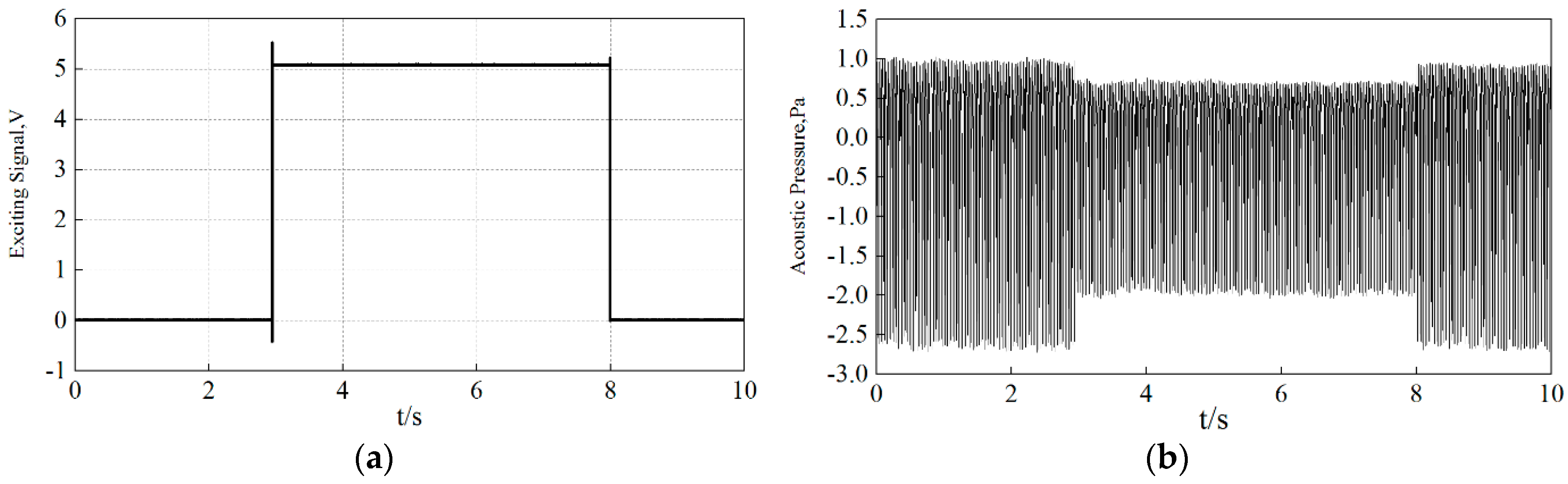
In the present complicated test system, some factors, including rotation fluctuation, the precisions of sensors and controllers, phase delay between actuator and controller, and rotor control system, may bring errors to the measurements. To reduce these uncertainties, repeated tests were conducted, and the averaged pressure signal over 20 revolutions was used in the post-processing of results. The signal sampling time in each condition was 10 s (about 180 revolutions of rotor). Figure 11a shows the input control signal from the host computer. First, the helicopter rotor operated at a baseline state where the winglet was in neutral position for 3 s, and then the controller sent a high level signal, and the amplifier applied an alternating voltage to the winglet for 5 s. The control signal was removed at the eighth second, and the rotor was recovered to the baseline state. Figure 11b is the noise signal collected by a microphone. The change of the sound pressure before and after the control can be clearly seen in the figure.
Due to the influences of rotor vibration, random air turbulence, and mechanical transmission, the noise signals contained broadband background noise. It was necessary to filter the measured signals before further analysis. The thickness noise was low-frequency noise, thus the basic principle of the filtering wave was to filter out irrelevant high-frequency components as much as possible while ensuring that the amplitude of the low-frequency component was unchanged. The classic Butterworth low-pass filter was used in signal processing, and the cut-off frequencies of the passband and the stopband were 300 Hz and 1000 Hz, respectively. The comparison of the time history and spectrum of the noise signal from the P22 microphone before and after filtering can be seen in Figure 12. The filtered sound pressure signal became smooth, and the amplitude of the first five orders and the total noise sound pressure level (SPL) were almost unchanged (94.62 dB to 94.29 dB), which indicated the effectiveness of the test data processing.
Firstly, we analyzed the test result in the condition of . Figure 13a gives the contour plot of differential sound pressure levels (SPLon-SPLoff) between the baseline and the control conditions on the 4 m spherical surface of the rotor center. It can be seen that the SPL in the observation area was effectively reduced when the control signal was applied, and the reduction of up to 3 dB was achieved near the rotor plane. The time histories of sound pressure at nine microphones are compared in Figure 13b. When the observations were at the same azimuthal angle, e.g., P3, P6, and P8 at 180°, the noise reduction in the rotor plane was the most obvious (P6) and gradually reduced with the elevation angle increase. The same trend was observed in other azimuths. This was because the anti-noise generated by the trailing edge winglet reached the largest value in the rotor plane. Comparing the observations in the rotor plane (P15, P6, P21), the noise reduction of the observations at 180° was the best and was lower at 150°and 210°.
For the hovering condition, due to the axisymmetric distribution of SPL, the control method could only reduce the noise in the areas of interest. However, for forward flight, the area with strong SPL was located in the front of the rotor, thus the peak SPL could be reduced by adjusting the control phase angle and amplitude. Although the noise behind the rotor increased, the overall SPL was reduced.
Then, the effects of the winglet control parameters (frequency, amplitude, and phase) on noise reduction were further analyzed. The variation of differential SPL (SPLon-SPLoff) with a deflection frequency at the P6 microphone is shown in Figure 14. The alternating voltage was kept at 60 ± 40 V. It can be seen that there was an optimal excitation angle at any frequency where the maximum noise reduction could be achieved. The optimal excitation angles corresponded to different frequencies. The angle for the first-order excitation was 270°, and those of the second-order and third-order controls were 180° and 90°, respectively.
In the hover condition, the distribution of SPL was axisymmetric, thus the optimal angle could be directly obtained through theoretical analysis. Learning from Equations (4) and (5), we know that the peaks of thickness and load noise were generated from the source at the azimuthal station that was 90° ahead of the observer, also explained by Figure 15. If an observer was at a 180° azimuth, the source at the azimuth of caused the greatest noise at this location. was the angle between the position and the radiation vector and could be neglected when the observer was far away from the rotor center. Therefore, the change rate (time derivative) of the exciting force needed to be maximized at an angle of 90° ahead of the observation position to reduce noise effectively. This meant that the time derivative of the deflection function should have been maximal at that azimuth. Taking the second-order frequency as an example, the deflection law of the winglet is: to maximize the time derivative at azimuth of 90°, the initial excitation angle is 180°. The test results given in Figure 14 are consistent with the theoretical analysis. Strictly speaking, the angle should have been included to obtain the exact angle of in this analysis because the observers were not located in far-field. However, due to the large interval (30°) used in the phase sweeping test, it covered the effect of , thus the results were similar to the theoretical analysis.
The four observations on the right and the left sides of the rotor (azimuth 150° and azimuth 210°) were selected to study the influence of the excitation phase angle. From Figure 15, we can conclude that the optimal exciting angles for observers at azimuths 150° and 210° were approximately 300° and 240° under the first-order excitation. Figure 16 gives the time-history of pressure of the two groups of microphones, i.e., P21, P23 and P15, P17 at their respective optimal control angles. For the P21 and P23 microphones, the SPL reductions were 2.33 dB and 1.95 dB, respectively, and for the P15 and P17 microphones, SPL reductions of 2.39 dB and 2.06 dB were obtained. It was clear that more noise reduction was achieved compared with the result from the case of , which was the optimal angle for observers at 180°. The relationship between the observer position and the initial excitation angle indicates that it is impossible to reduce noise at all observations at the same time, but noise in a certain direction can be reduced through designing a particular exciting law. In forward flight condition, the derived relation is partially valid for the observers in a small area straight ahead of the rotor because of the superimposition of forward speed, but it can serve as a reference in analyzing problems.
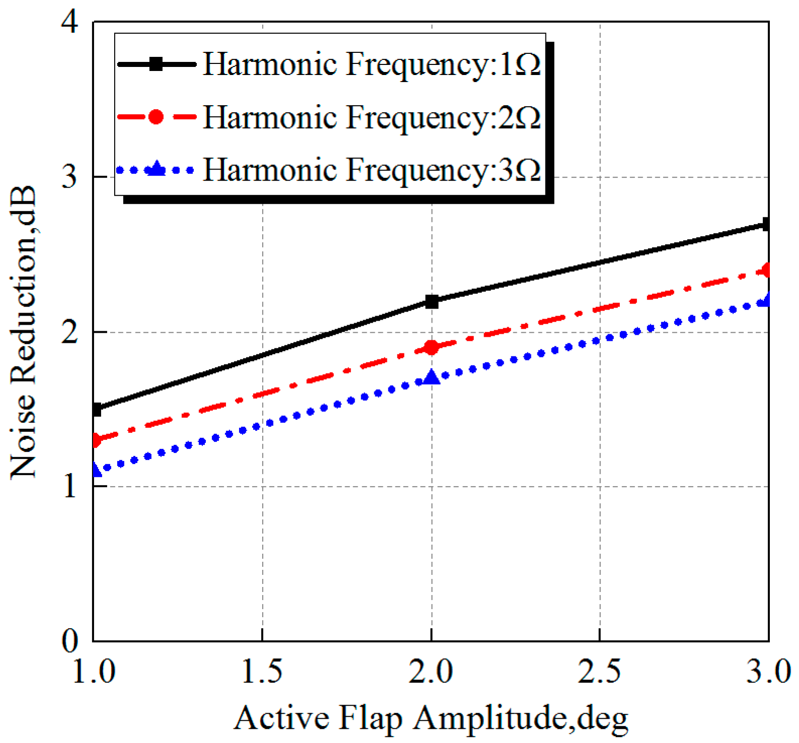
Finally, the variations of thickness noise reduction with the winglet deflection amplitudes were analyzed. As shown in Figure 17, when the deflection frequency was constant, the larger the deflection amplitude of the winglet generated the stronger unsteady force, thereby improving the ability of noise reduction. However, the test result also showed that the noise reduction amplitude decreased with the increase of the frequency under the same deflection angle, which was inconsistent with the theoretical analysis presented in Section 2. By analysis, the actual deflection angle of the winglet in this test may have contributed to this disagreement. As mentioned above, the deflection angle in this test was not directly measured and controlled but was obtained by indirect conversion from the input alternating voltage. The deflection angle in a rotating environment is less than that in a non-rotating environment due to the effect of centrifugal force. Additionally, the winglet deflection angle decreases as the frequency increases when input voltage or power is constant. Therefore, a larger-sized helicopter rotor will be designed in future research, and an angular displacement feedback control system will be introduced to monitor and adjust the deflection angle of the winglet in real time to meet the target value.
4. Conclusions
A noise reduction technique for the rotor thickness noise using a force actuator on the blade tip was developed. Both numerical and experimental studies were carried out to study the noise reduction mechanism. From the results, the following conclusions can be drawn:
- (1)
- The sound pressure of rotor thickness noise is characterized by a significant negative pulse caused by the time derivative of the blade surface velocity. The noise reduction can be achieved by using an unsteady excitation force at the rotating blade tip to generate an opposite sound waveform (anti-noise) as the thickness noise with a well-designed control law. The time derivative of the control force dominates the magnitude and the phase of anti-noise.
- (2)
- The trailing edge winglet with high-frequency motion is equipped at the rotor blade tip to generate the unsteady control force. When the windward area of the winglet changes periodically, anti-noise can be generated by the resultant in-plane force. A smart drive mechanism combining piezoelectric stack and diamond-shaped amplifiers was designed to drive the high-frequency motion of th ewinglet. Driving frequency up to 120 Hz (three harmonics of rotation frequency) and approximately 3° deflection angle of the winglet was achieved in testing.
- (3)
- The test results show that the noise in the front area of the rotor was effectively reduced, and the noise reduction up to 3 dB was achieved in the plane of the rotor disk under the control law of the first-order frequency and the 3° deflection angle of the winglet. Moreover, the noise reduction at the observation position strongly related to the azimuth angles, which is independent of pitch angle and distances. This indicates that the rotor noise in a certain area, but not all areas, can be reduced through designing a particular control law.
- (4)
- The deflection amplitude, frequency, and initial excitation phase angle are governing parameters that affect noise control. The magnitude of noise reduction is proportional to the deflection angle of the winglet, however, the effect of frequency and initial excitation phase angle is combined. For each frequency, there is always an optimal initial excitation phase angle to minimize the noise level, but it varies with control frequency. The relationship between control phase and frequency was derived in this paper.
- (5)
- The previous study in reference 25 states that the anti-noise is generated from the lift change of the blade, not the active flap. The flap alters the blade torsion and changes the local angle of attack and lift, which is responsible for the generation of in-plane force needed for the noise reduction at the target observer. In the present study, the small-scale rotor was stiff in torsion, and the blade torsion induced by the active flap was very small. The results indicate that noise reduction can also be achieved by relying solely on the high-frequency motion of the winglet. It is one finding from our test that needs to be further verified by sophisticated simulation work.
The theoretical study indicated that the effectiveness of noise reduction increased with the increment of frequency when the deflection amplitude was constant, yet the experimental results herein give the opposite trend. The most probable reason is that deflection angle in this test was converted by voltage rather than direct measurement. In future research, a larger-scale rotor with an angular displacement feedback control system will be designed to monitor and adjust the deflection angle of the winglet in real time.
Author Contributions
Conceptualization and project administration, Y.S.; Writing-original draft preparation, T.L.; Writing-review & editing, G.X.; Validation, X.H. and L.D.
Funding
This work was supported by the Fundamental Research Funds for the Central Universities (No. NS2018007).
Acknowledgments
The authors will thank Jinlong Zhou for his great help in experimental design.
Conflicts of Interest
The authors declare no conflict of interest.
References
- Brentner, K.S.; Farassat, F. Helicopter Noise Prediction: The Current Status and Future Direction. J. Sound Vib. 1994, 170, 79–96. [Google Scholar] [CrossRef]
- Baeder, J.D. Passive Design Reductions of High-Speed Impulsive Rotor Noise. J. Am. Helicopter Soc. 1998, 43, 222–234. [Google Scholar] [CrossRef]
- Chae, S.; Yee, K.; Yang, C.; Aoyama, T.; Jeong, S.; Obayashi, S. Helicopter rotor shape optimization for the improvement of aeroacoustic performance in hover. J. Aircr. 2010, 47, 1770–1783. [Google Scholar] [CrossRef]
- Edwards, B.; Cox, C. Revolutionary Concepts for Helicopter Noise Reduction: SILENT Program; Report No.:NASA/CR-2002-211650; NASA Langley Research Center: Hampton, VA, USA, 2002.
- Yung, H.Y. Rotor Blade-Vortex Interaction Noise. Prog. Aerosp. Sci. 2000, 36, 97–115. [Google Scholar] [CrossRef]
- Barakos, G.N.; Garcia, A.J. CFD analysis of hover performance of rotors at full and model-scale conditions. Aeronaut. J. 2016, 120, 1386–1423. [Google Scholar] [CrossRef]
- Rauch, P.; Gervais, M.; Cranga, P.; Baud, A.; Hirsch, J.F.; Walter, A.; Beaumier, P. Blue edge: The design, development and testing of a new blade concept. In Proceedings of the 67th Annual Forum of the American Helicopter Society, Virginia Beach, VA, USA, 3–5 May 2011; pp. 542–555. [Google Scholar]
- Nguyen, K.; Betzina, M.; Kitaplioglu, C. Full-Scale Demonstration of Higher Harmonic Control for Noise and Vibration Reduction on the XV-15 Rotor. J. Am. Helicopter Soc. 2001, 46, 182–191. [Google Scholar] [CrossRef]
- Splettstoesser, W.R.; Kube, R.; Wagner, W.; Seelhorst, U.; Boutier, A.; Micheli, F.; Pengel, K. Key results from a higher harmonic control aeroacoustic rotor test (HART). J. Am. Helicopter Soc. 1997, 42, 58–78. [Google Scholar] [CrossRef]
- Anobile, A.; Bernardini, G.; Gennaretti, M. Investigation on a High-Frequency Controller for Rotor BVI Noise Alleviation. Int. J. Acoust. Vib. 2016, 21, 239–248. [Google Scholar] [CrossRef]
- Jacklin, S.A.; Blaas, A.; Teves, D.; Kube, R. Reduction of helicopter bvi noise, vibration and power consumption through individual blade control. In Proceedings of the AHS 51st Annual Forum and Technology Display, Fort Worth, TX, USA, 9–11 May 1994. [Google Scholar]
- Küfmann, P.; Bartels, R.; Kessler, C.; van der Wall, B.G. On the design and development of a multiple swashplate control system for the realization of individual blade control (IBC) for helicopters. In Proceedings of the 67th Annual Forum of the American Helicopter Society, Virginia Beach, VA, USA, 3–5 May 2011. [Google Scholar]
- Aoyama, T.; Yang, C.; Kondo, N.; Saito, S. Comparison of Noise Reduction Effect between AFC and Conventional IBC by Moving Overlapped Grid Method. In Proceedings of the 12th AIAA/CEAS Aeroacoustics Conference, Cambridge, MA, USA, 8–10 May 2006. [Google Scholar]
- Kobiki, N.; Murashige, A.; Tsuchihashi, A.; Yamakawa, E. Experimental Study of Active Techniques for Blade/Vortex Interaction Noise Reduction. Trans. Jpn. Soc. Aeronaut. Space Sci. 2009, 52, 159–167. [Google Scholar] [CrossRef] [Green Version]
- Straub, F.; Anand, V.; Birchette, T.; Lau, B. Wind Tunnel Test of the SMART Active Flap Rotor. In Proceedings of the American Helicopter Society 65th Annual Forum and Technology Display, Grapevine, TX, USA, 27–29 May 2009. [Google Scholar]
- Modini, S.; Graziani, G.; Bernardini, G.; Gennaretti, M. Blade-Vortex Interaction Noise Controller Based on Miniature Trailing Edge Effectors. Int. J. Acoust. Vib. 2018, 23, 378–384. [Google Scholar] [CrossRef]
- Nelson, C.T.; Rediniotis, O.K. Active flap deployment system for blade-disturbance interaction alleviation. J. Fluids Eng. Trans. ASME 2004, 126, 1006–1014. [Google Scholar] [CrossRef]
- Saito, S.; Kobiki, N.; Tanabe, Y. Application of an active device for helicopter noise reduction in JAXA. Fluid Dyn. Res. 2010, 42, 015006. [Google Scholar] [CrossRef]
- Booth, E.R.; Wilbur, M.L. Acoustic aspects of Active-Twist Rotor control. J. Am. Helicopter Soc. 2004, 49, 3–10. [Google Scholar] [CrossRef]
- Chen, P.C.; Baeder, J.D.; Evans, R.A.D.; Niemczuk, J. Blade-vortex interaction noise reduction with active twist smart rotor technology. Smart Mater. Struct. 2001, 10, 77–85. [Google Scholar] [CrossRef]
- Gaurav, G.; Schmitz, F.H. Helicopter Thickness Noise Reduction Possibilities Through Active On-Blade Acoustic Control. J. Aircr. 2010, 47, 41–52. [Google Scholar] [CrossRef]
- Gopalan, G.; Schmitz, F.H. Low harmonic near-in-plane far-field helicopter noise cancellations using distributed on-blade controls. In Proceedings of the AHS Southwest Region Technical Specialists’meeting, Dallas-Fort Worth, TX, USA, 15–17 October 2008. [Google Scholar]
- Sim, B.W. Suppressing In-Plane, Low Frequency Helicopter Harmonic Noise with Active Controls. In Proceedings of the American Helicopter Society San Francisco Bay Area Chapter’s Aeromechanics Specialist’s Meeting, San Francisco, CA, USA, 22–24 January 2008. [Google Scholar]
- Yang, T.X.; Brentner, K.S.; Walsh, G.D. A Dual Compact Model for Rotor Thickness Noise Prediction. J. Am. Helicopter Soc. 2018, 63, 12–23. [Google Scholar] [CrossRef]
- Sim, B.W.; JanakiRam, R.D.; Lau, B.H. Reduced In-Plane, Low Frequency Noise of an Active Flap Rotor. J. Am. Helicopter Soc. 2014, 59, 1–17. [Google Scholar] [CrossRef]
- Sargent, D.C.; Schmitz, F.H. Fundamental Experimental Studies Supporting Active-Jet Acoustic Control of In-Plane Rotor Harmonic Noise. J. Aircr. 2014, 51, 434–446. [Google Scholar] [CrossRef]
- Farassatm, F.; Succi, G.P. The prediction of helicopter discrete frequency noise. Vertica 1983, 7, 309–320. [Google Scholar]
- Zhao, Y.Y.; Shi, Y.J.; Xu, G.H. Helicopter blade-vortex interaction airload and noise using coupling CFD/VWM method. Appl. Sci. 2017, 7, 381. [Google Scholar] [CrossRef]
Figure 1.
The directivity and composition of rotor thickness noise.
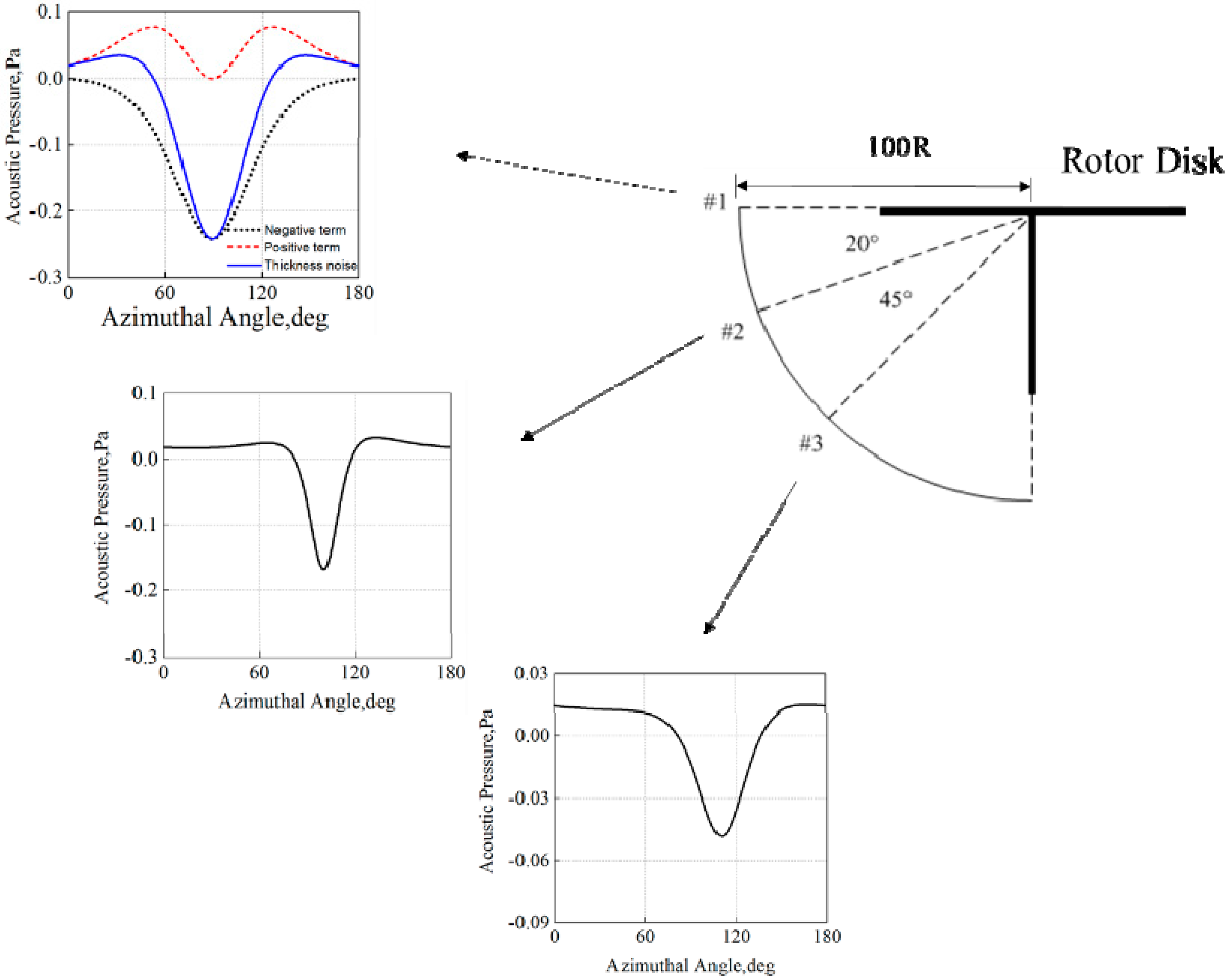
Figure 2.
The schematic of noise field cancelation using exciting force.
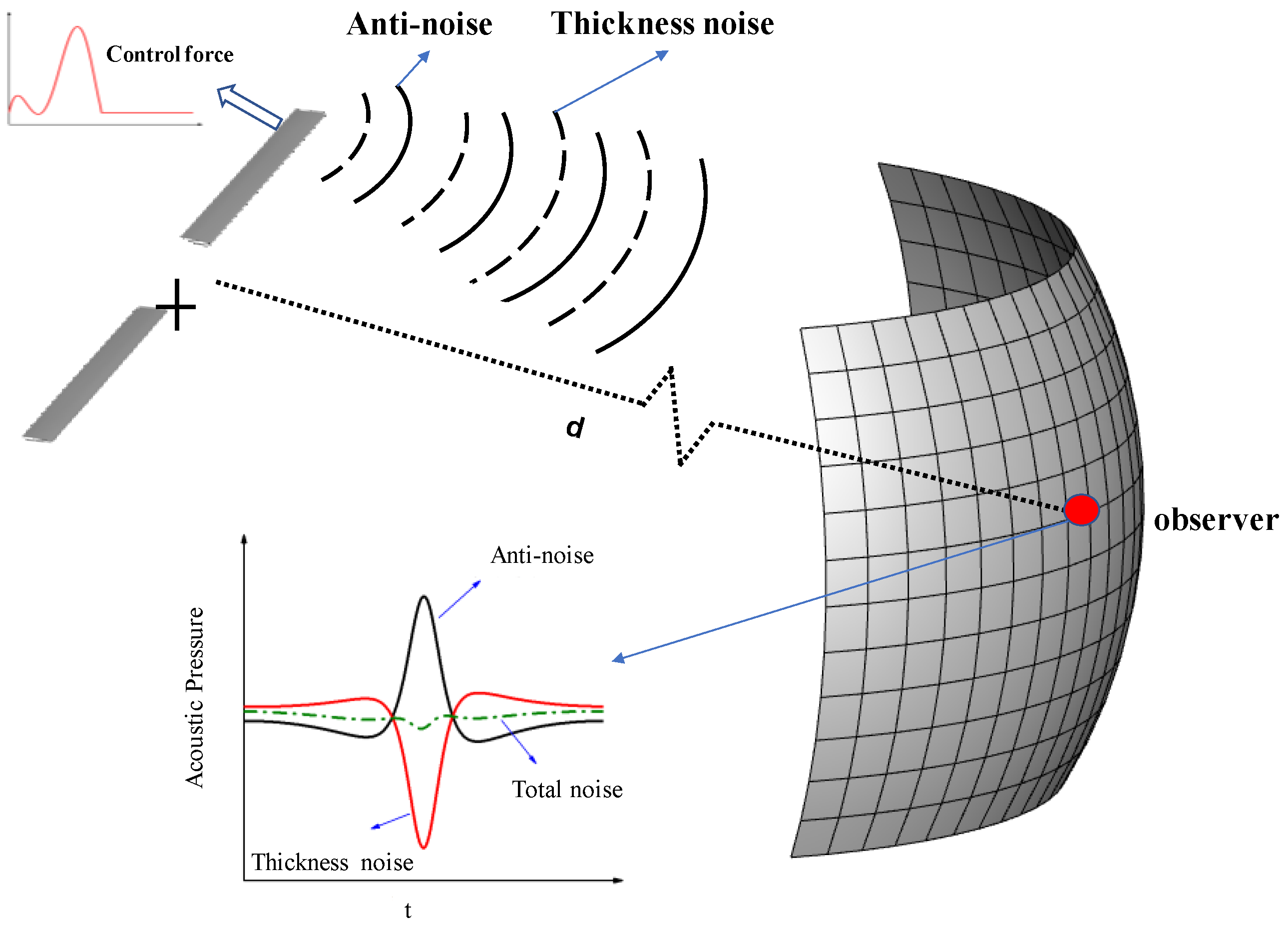
Figure 3.
Noise pressure generated by exciting force.
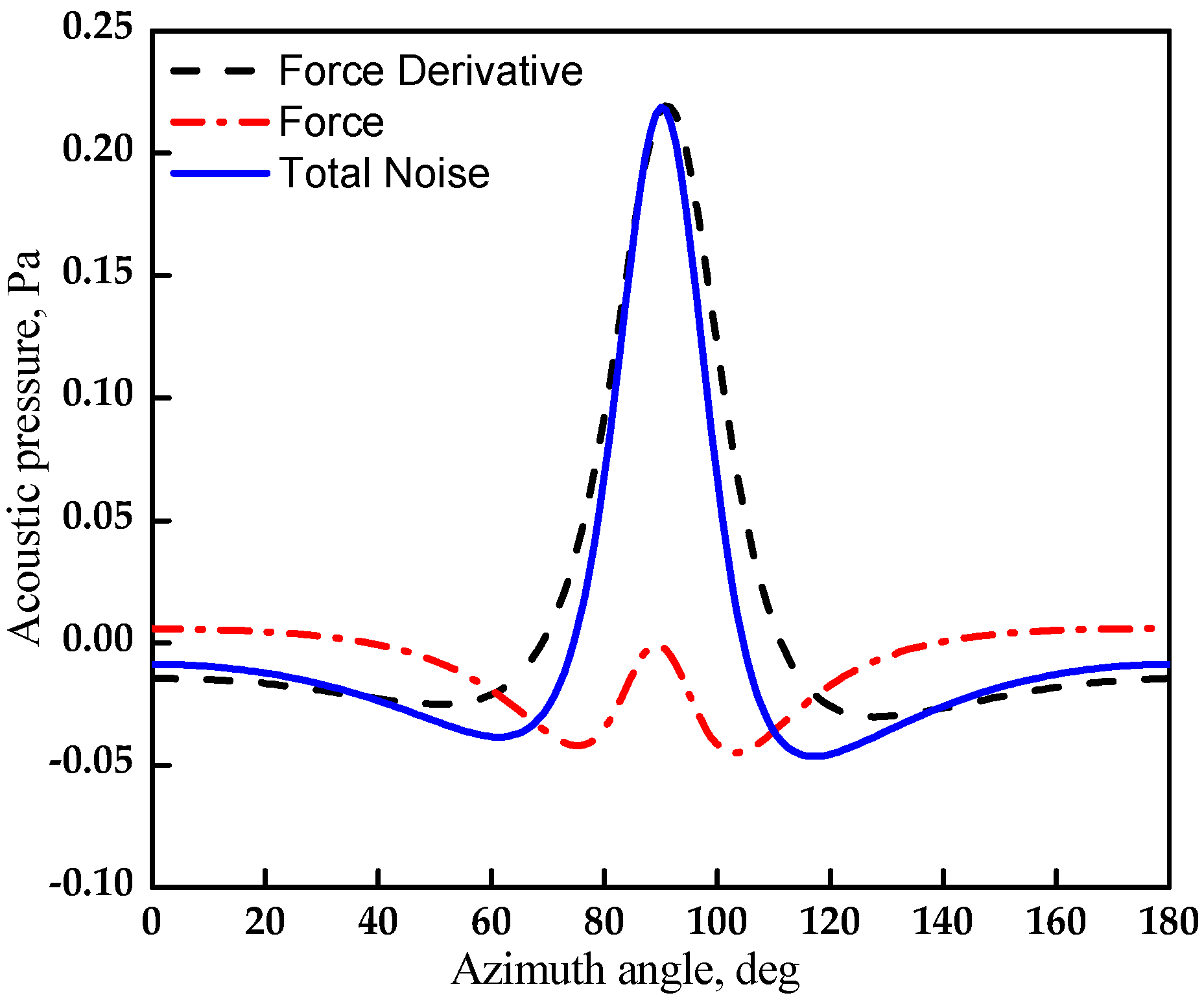
Figure 4.
The effect of force amplitude on noise reduction: (a) , (b) , (c) .
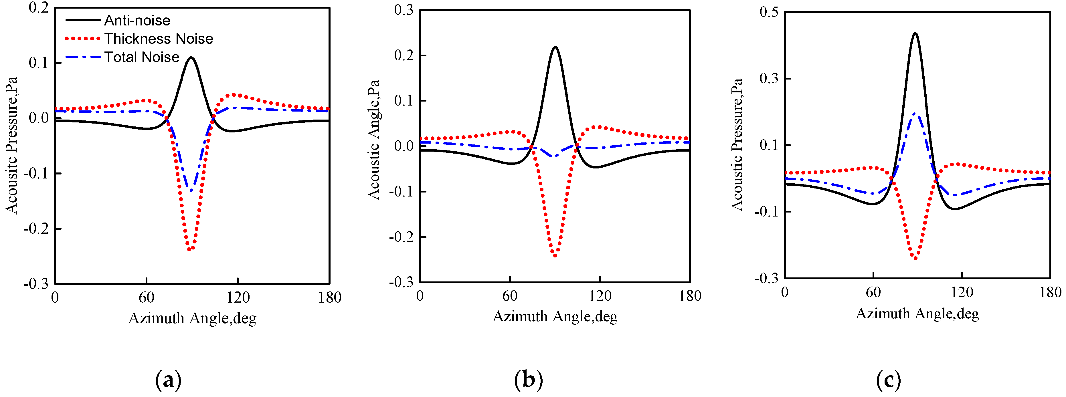
Figure 5.
The effect of force frequency on noise reduction: (a) , (b) , (c) .

Figure 6.
The schematic of the rotor with a trailing-edge winglet: (a) rotor planform, (b) airfoil section, (c) exciting force generated by winglet.
Figure 6.
The schematic of the rotor with a trailing-edge winglet: (a) rotor planform, (b) airfoil section, (c) exciting force generated by winglet.

Figure 7.
The rotor model used in the experiment: (a) blade planform, (b) blade model.
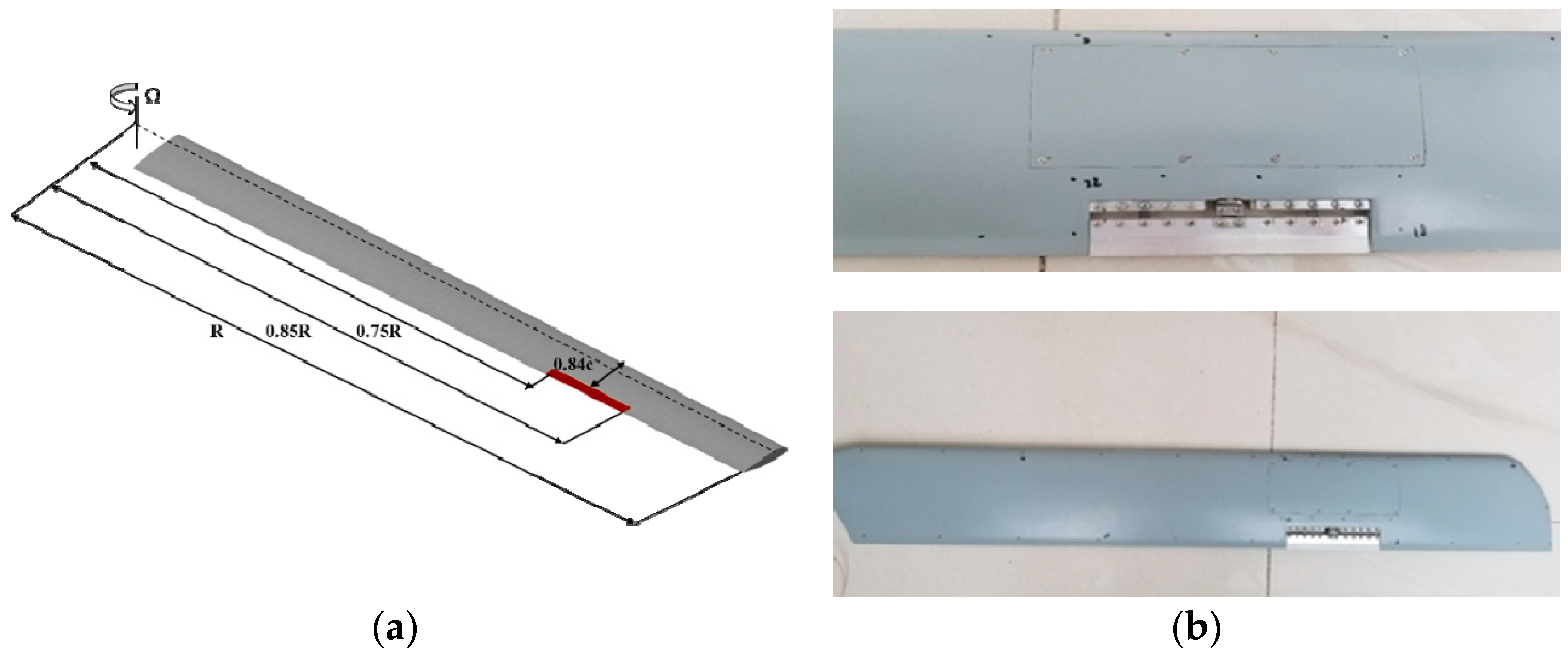
Figure 8.
The drive mechanism of the trailing-edge winglet: (a) connectivity of drive mechanism, (b) piezoelectric stack.
Figure 8.
The drive mechanism of the trailing-edge winglet: (a) connectivity of drive mechanism, (b) piezoelectric stack.

Figure 9.
The principle diagram of the test control system.
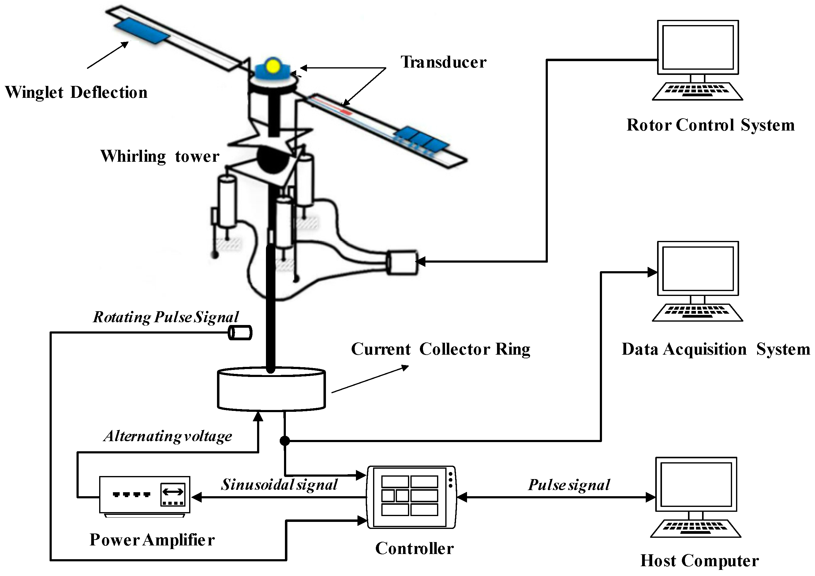
Figure 10.
The experimental facilities: (a) rotor system, (b) anechoic chamber, (c) microphone positions.
Figure 10.
The experimental facilities: (a) rotor system, (b) anechoic chamber, (c) microphone positions.
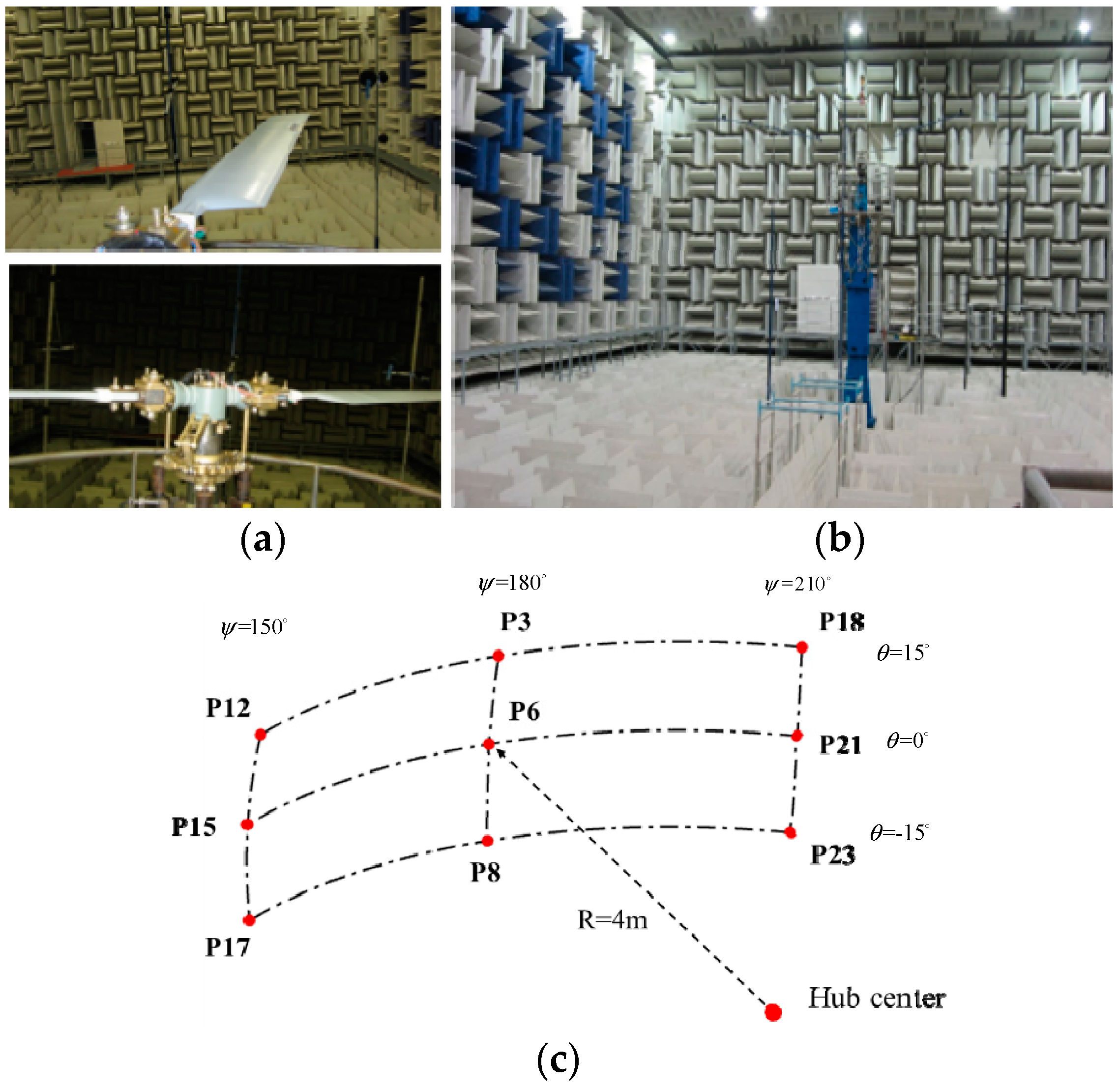
Figure 11.
The input control signal and collected noise signal: (a) control signal, (b) noise signal.
Figure 11.
The input control signal and collected noise signal: (a) control signal, (b) noise signal.

Figure 12.
The comparison of the signal at the P22 microphone with and without filtering: (a) original signal, (b) filtered signal.
Figure 12.
The comparison of the signal at the P22 microphone with and without filtering: (a) original signal, (b) filtered signal.

Figure 13.
The noise reduction in the condition of : (a) contour plot of differential sound pressure level (SPL), (b) time history of sound pressure.
Figure 13.
The noise reduction in the condition of : (a) contour plot of differential sound pressure level (SPL), (b) time history of sound pressure.
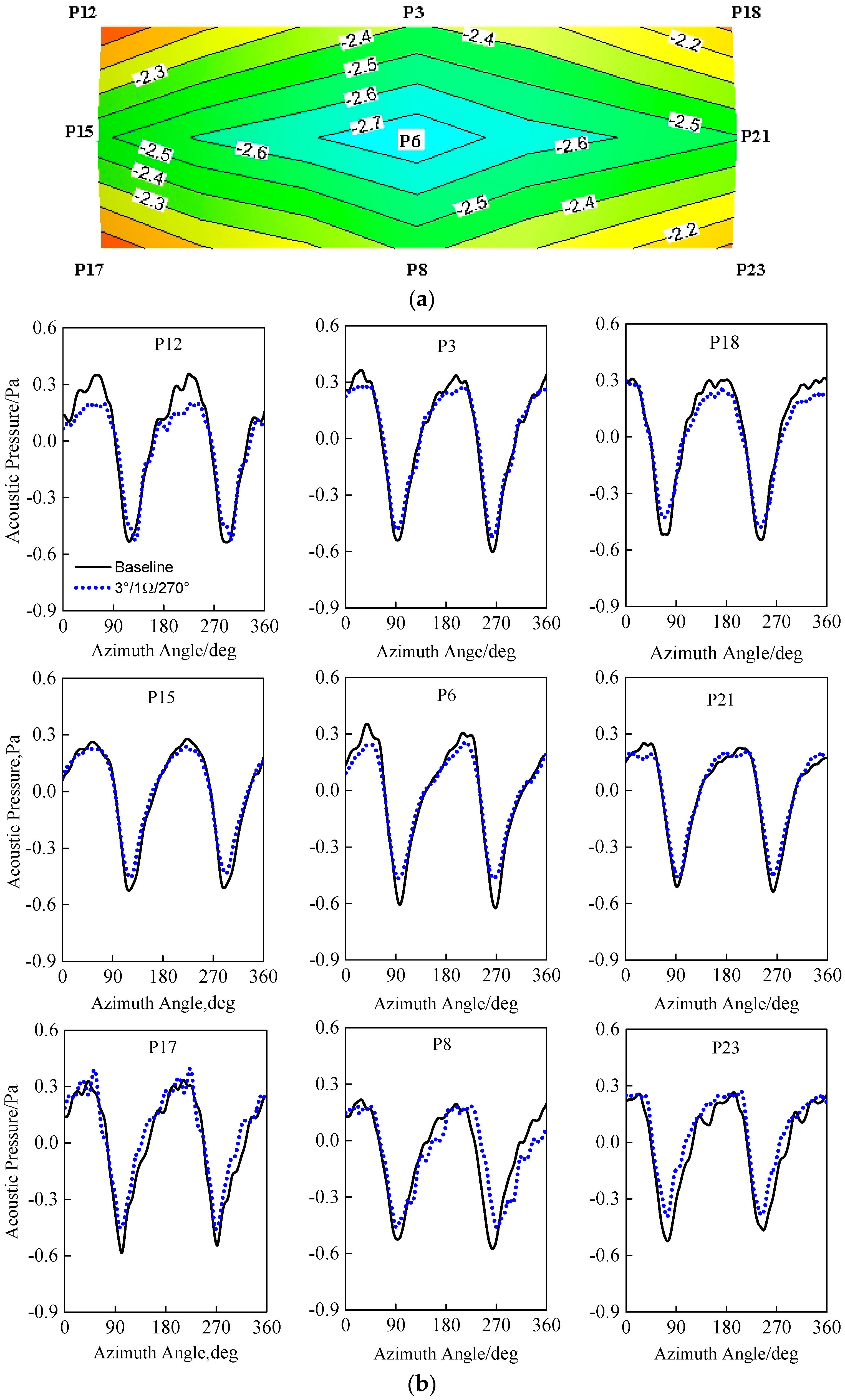
Figure 14.
The differential SPL varies at the P6 microphone with deflection frequency: (a) , (b) , (c) .
Figure 14.
The differential SPL varies at the P6 microphone with deflection frequency: (a) , (b) , (c) .
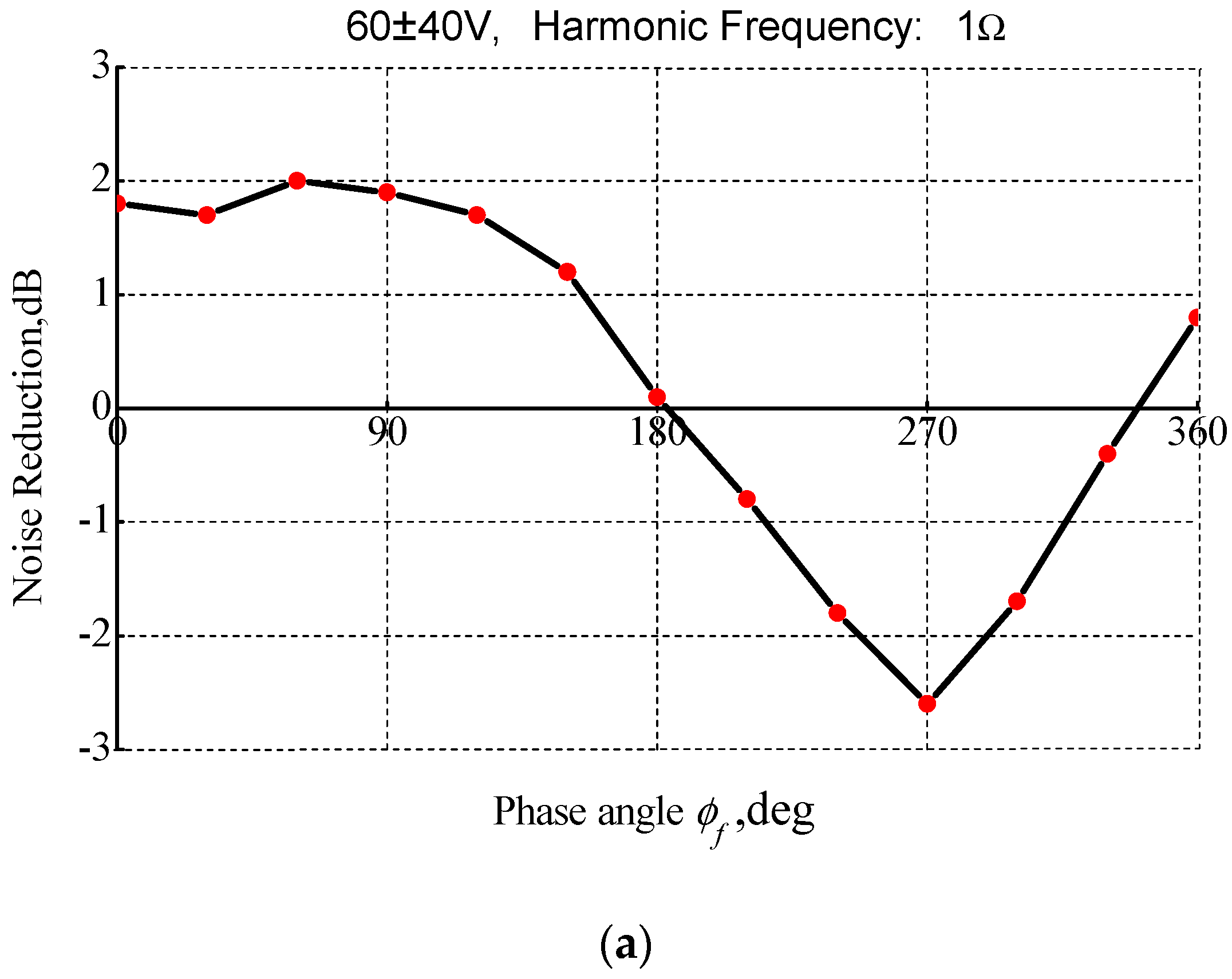
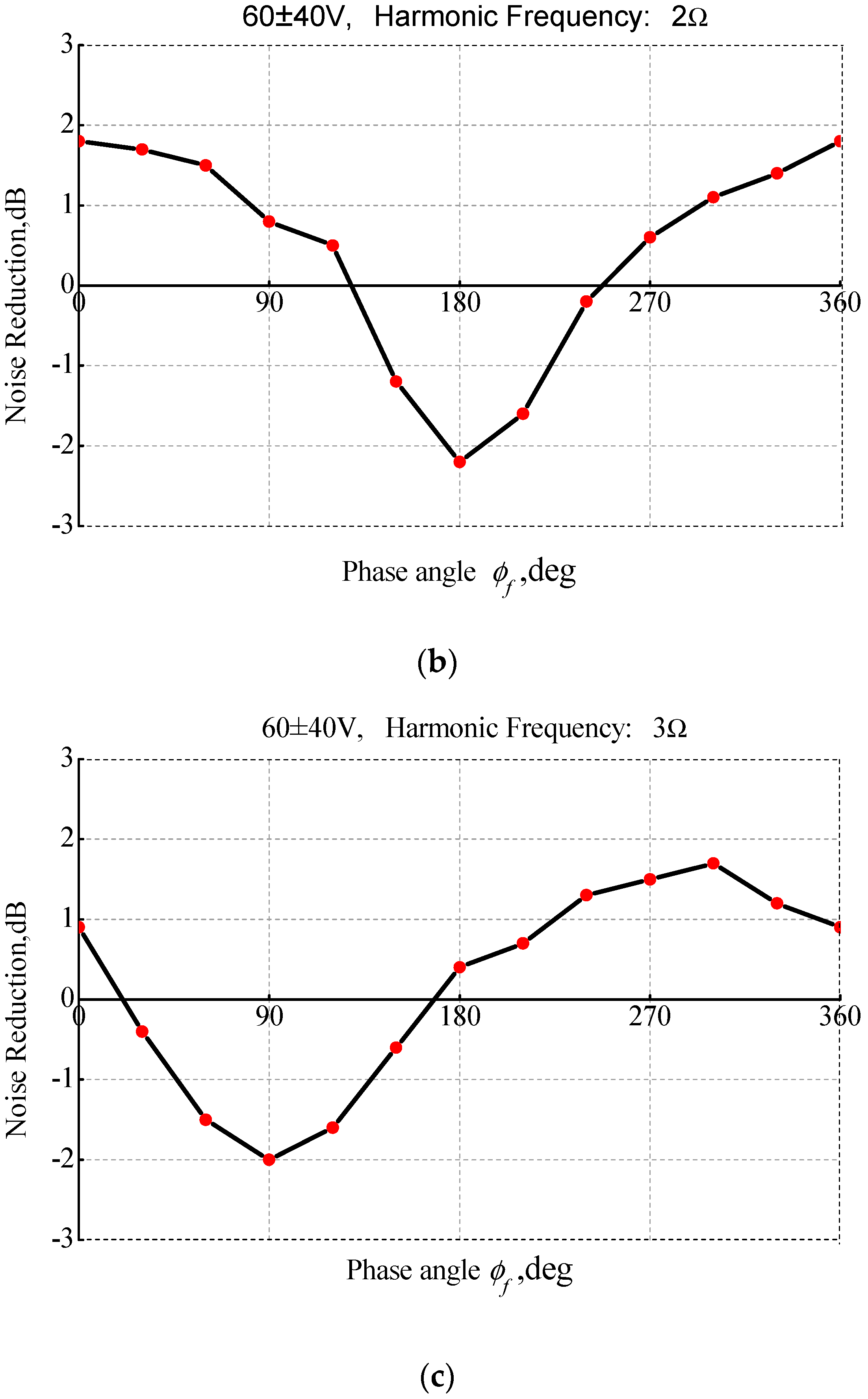
Figure 15.
The phase relationship between observer and source.

Figure 16.
The noise reduction at optimal exciting phases: (a) P15, (b) P17, (c) P21, (d) P23.
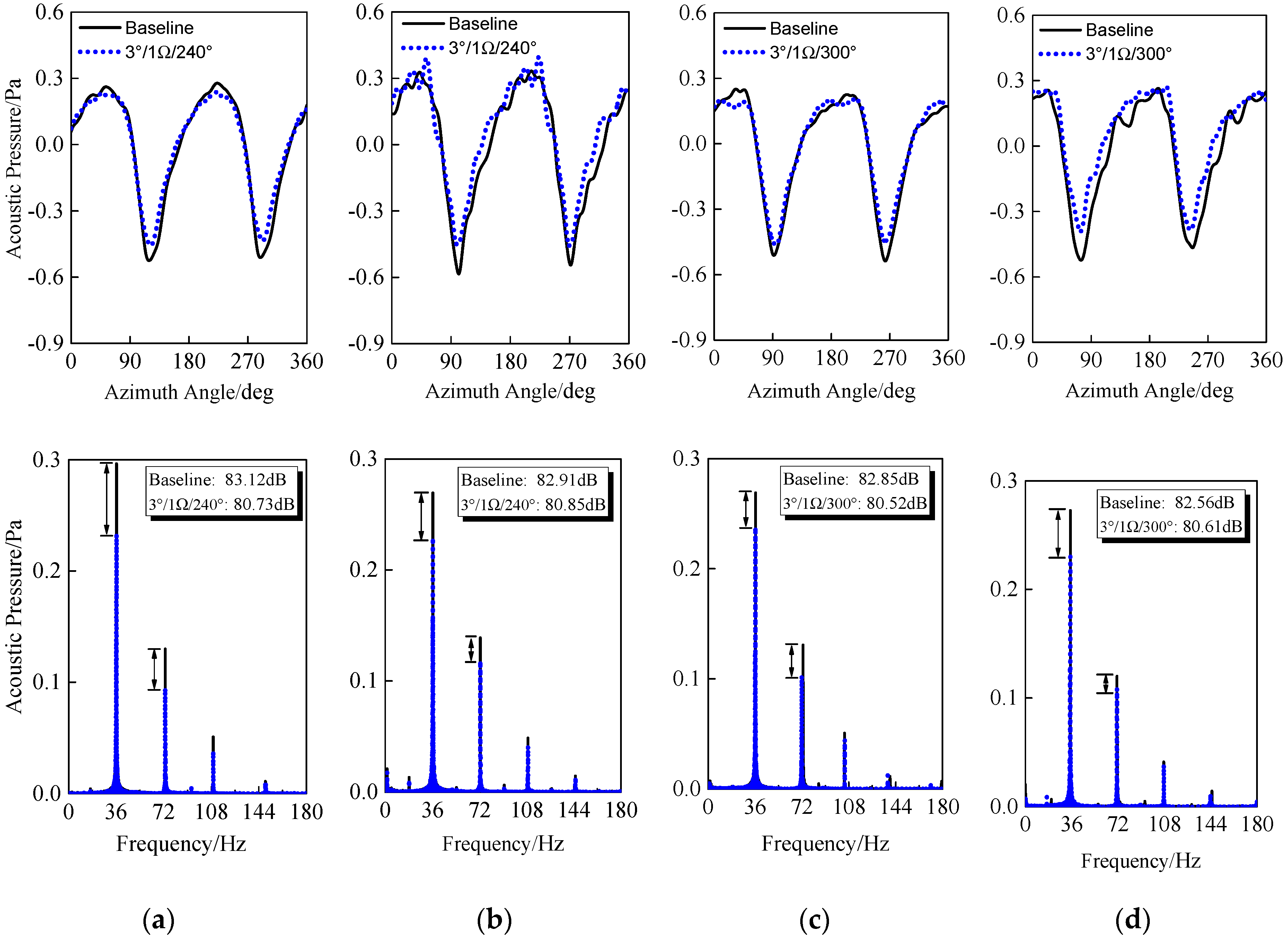
Figure 17.
The SPL reduction varies with deflection amplitude.

Table 1.
Rotor operation conditions in experiment.
| Parameter | Value |
|---|---|
| Rotation speed, | |
| Rotation frequency, | 18 Hz |
| Collective pitch | |
| Deflection rate, | |
| Alternating voltage | |
| Initial phase azimuth, |
© 2019 by the authors. Licensee MDPI, Basel, Switzerland. This article is an open access article distributed under the terms and conditions of the Creative Commons Attribution (CC BY) license (http://creativecommons.org/licenses/by/4.0/).
Share and Cite
MDPI and ACS Style
Shi, Y.; Li, T.; He, X.; Dong, L.; Xu, G. Helicopter Rotor Thickness Noise Control Using Unsteady Force Excitation. Appl. Sci. 2019, 9, 1351. https://doi.org/10.3390/app9071351
AMA Style
Shi Y, Li T, He X, Dong L, Xu G. Helicopter Rotor Thickness Noise Control Using Unsteady Force Excitation. Applied Sciences. 2019; 9(7):1351. https://doi.org/10.3390/app9071351
Chicago/Turabian StyleShi, Yongjie, Teng Li, Xiang He, Linghua Dong, and Guohua Xu. 2019. "Helicopter Rotor Thickness Noise Control Using Unsteady Force Excitation" Applied Sciences 9, no. 7: 1351. https://doi.org/10.3390/app9071351
Note that from the first issue of 2016, this journal uses article numbers instead of page numbers. See further details here.