Path Tracking of Mining Vehicles Based on Nonlinear Model Predictive Control


1
School of Mechanical Engineering, University of Science and Technology Beijing, Beijing 100083, China
2
Institute of Artificial Intelligence, University of Science and Technology Beijing, Beijing 100083, China
*
Author to whom correspondence should be addressed.
Appl. Sci. 2019, 9(7), 1372; https://doi.org/10.3390/app9071372
Submission received: 3 March 2019
/
Revised: 24 March 2019
/
Accepted: 25 March 2019
/
Published: 1 April 2019
(This article belongs to the Special Issue Multi-Actuated Ground Vehicles: Recent Advances and Future Challenges)
Abstract
:Featured Application
This work is used for unmanned mining vehicles or articulated mobile robots.
Abstract
Path tracking of mining vehicles plays a significant role in reducing the working time of operators in the underground environment. Because the existing path tracking control of mining vehicles, based on model predictive control, is not very effective when the longitudinal velocity of the vehicle is above 2 m/s, we have devised a new controller based on nonlinear model predictive control. Then, we compare this new controller with the existing model predictive controller. In the results of our simulation, the tracking accuracy of our controller at the longitudinal velocity of 4 m/s is close to that of the existing model predictive controller, at the longitudinal velocity of 2 m/s. When longitudinal velocity is 4 m/s, the existing model predictive controller cannot drive the mining vehicle to track the given path, but our nonlinear model predictive controller can, and the maximum displacement error and heading error are 0.1382 m and 0.0589 rad, respectively. According to these results, we believe that this nonlinear model predictive controller can be used to improve the performance of the path tracking of mining vehicles.
1. Introduction
In the underground mining environment, ensuring the safety of operators is very important and difficult. Compared with traditional mining systems, automatic systems can reduce the working time of operators, and less working time can ensure better safety [1,2,3]. Automatic mining systems often include unmanned articulated vehicles, so path tracking, as a core part of unpiloted technology, plays an important role. The task of path tracking is to drive vehicles to track the given path [4,5,6].
Currently, model predictive control (MPC) is a widely used path tracking control method [7,8,9,10,11,12,13,14,15,16]. The biggest advantage of MPC over other control methods, such as pure pursuit control [17], feedforward-feedback control [18], and sliding mode control [19,20,21,22], is that it can take constraints of the system into account explicitly [23]. This advantage is very beneficial for solving the problem of path tracking under actuator saturation and other system constraints.
Studies of the path tracking of articulated vehicles can also prove that the system constraint is not considered in control methods other than MPC. In the work of Dekker et al., the difference in the articulated angle speed between the actual vehicle and the model is clearly caused by system constraints [24]. Tan et al. did not give control variables in their paper [25]. In the work of Zhao et al., the articulated angle speed is also significantly larger than the limit of real vehicles [26]. In addition, Sasiadek et al. mentioned that not considering constraints is the weakness of their work [27]. Although there are hardware devices to prevent over-constraints in actual vehicles, frequent activation of such devices not only increases operating costs but may also cause danger. It is very advantageous to use MPC to solve this problem at the controller level.
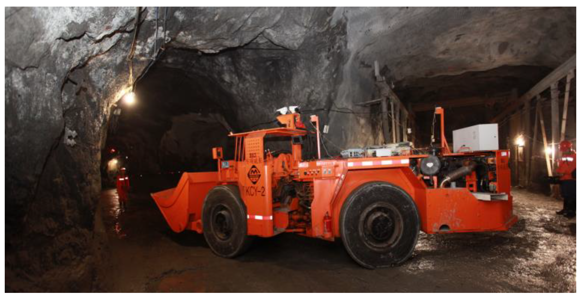
However, there are few papers on path tracking of mining vehicles based on MPC due to the special articulated steering structure of mining vehicles. A mining vehicle is shown in Figure 1. Until now, only Nayl et al. have devised a path tracking controller for articulated vehicles based on switching-MPC [28,29,30]. There is no doubt that the work of Nayl et al. is groundbreaking, but there are still some problems with their controller.
For the MPC-based controller, the predicted error is one that the controller needs to eliminate in the future. Nayl et al. derives the prediction model based on an error model, thus future errors are predicted based on current errors and possible future inputs [28,29,30]. If the control input is assumed to be unchanged, after a sampling interval of this model, the predicted error is shown in Figure 2. When the curvature and heading of the given path are invariant, the longitudinal velocity of mining vehicles affects the reliability of predicted errors. When longitudinal velocity is slow, the reliability of predicted errors is high, as shown in Figure 2a. In contrary, when longitudinal velocity is fast, the reliability of predicted errors is low, as shown in Figure 2b. These characteristics make that Nayl et al.’s controller performs not good enough when the longitudinal velocity is fast. In Figure 2, is the predicted displacement error and is the actual future displacement error.
By analyzing the researches about MPC, we find that the nonlinear model predictive control (NMPC) is more suitable to solve this problem [7,8,9,10,11,12,13,14,15,16]. Compared to the linear time-varying model predictive control (LTV-MPC) [7,8,9,10], the NMPC has a longer accurate prediction horizon [11,12,13,14,15,16]. Thus, an NMPC-based controller is designed and presented in this paper to improve the accuracy of the control system when the longitudinal velocity of mining vehicles is fast. The performance of this path tracking controller is verified by simulation, and a path tracking controller devised by Nayl et al. is taken as a comparison. In the results of our simulation, the maximum displacement error and maximum heading error of the path tracking system based on NMPC are 0.1382 m and 0.0589 rad, respectively. Besides, when above tracking accuracy is achieved, the longitudinal velocity of the NMPC controller is 4 m/s, and the switching-MPC controller can achieve similar tracking accuracy at only 2 m/s. Therefore, we believe that our work is significant to the unmanned driving of articulated vehicles.
2. Controller Design
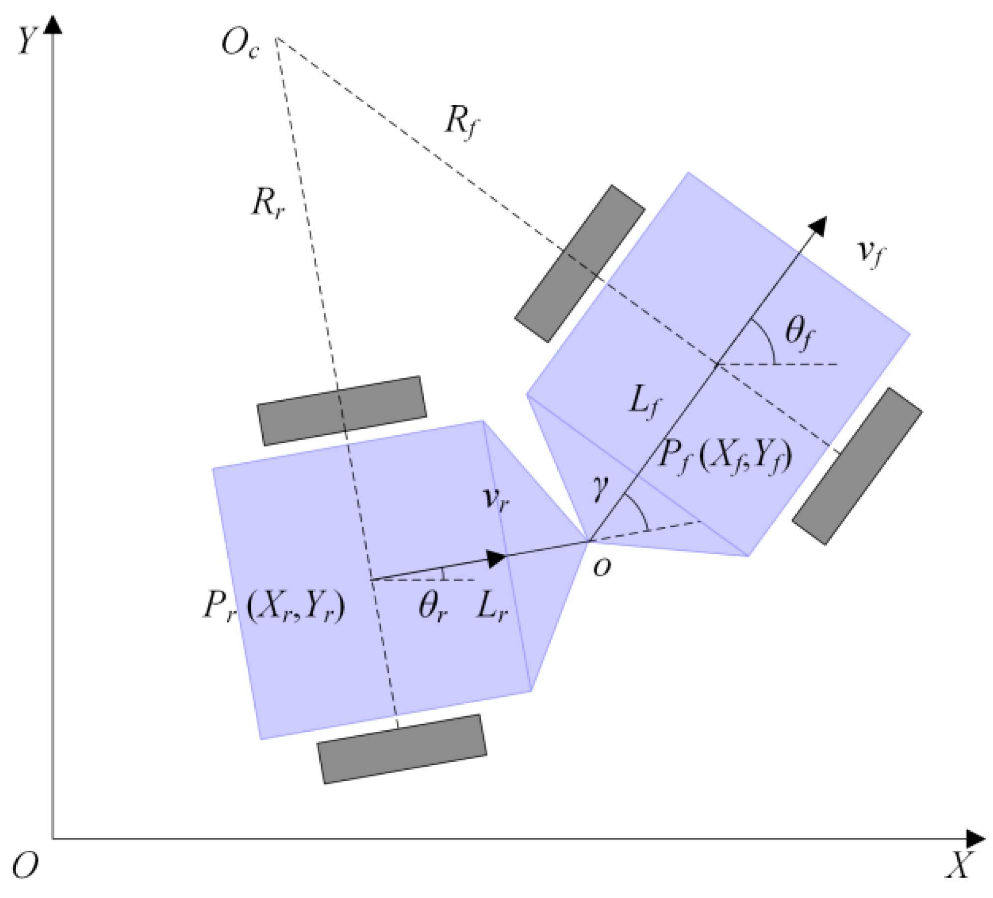
The two most critical steps during designing a path tracking controller for mining vehicles based on NMPC are establishing a prediction model and designing a rolling optimization function. In order to obtain the error between future mining vehicles and the given path, the prediction model should predict the future vehicle pose based on the current vehicle pose and future control inputs. This model can be designed based on a kinematics model because there is some research showing that the kinematics model can simulate movement characteristics of mining vehicles [3,28,29,30,31,32,33,34]. In this kinematics model, bodies of the mining vehicle are considered as the rigid body, and the force analysis of tires is ignored. Figure 3 shows the kinematics of mining vehicles. Table 1 shows the physical meaning of the parameters. At the articulated point, the velocity of the front body is the same as that of the rear body. Therefore, in the fixed coordinate system , the kinematic model of mining vehicles can be deduced from the following formulas:
For mining vehicles, the pose of the front axle center is often used as the control target:
The kinematic model of mining vehicles can be obtained by simultaneous formulas (1) and (2), which can be rewritten as a matrix:
where is the articulated angular speed.
The kinematics model (3) can be abbreviated as:
where:
If the sampling interval is small enough, the value of changes are very small during this period. Thus:
where is the predicted state of mining vehicles at , especially, is the current state.
Bring (4) to (6):
Then, all state information of mining vehicles in the prediction horizon can be obtained:
where is the prediction horizon and is the control horizon.
Therefore, the errors between the future mining vehicle and the given path are:
where is the information on the given path.
In addition, in order to make the control as smooth as possible, the following items to the optimization goal are added:
where is the control input before a sampling interval and it is a known quantity.
Then, the optimization objective function is defined as:
Therefore, rolling optimization is to solve the constrained optimization problem in every sampling period:
In the above equations, is weight factor of relaxation factor , , and are the weight matrices, , , and are the system constraints of the mining vehicle. These constraints are hard constraints. Since the mining vehicle usually travels at a slow longitudinal velocity, the large centrifugal force does not exist. Therefore, soft constraints, such as lateral acceleration, are not added.
The control inputs in the control horizon can be obtained by solving (12):
The first element is the real control input of the path tracking system:
These control inputs continue until the next sampling period.
3. Simulation
The simulation environment is MATLAB/Simulink 2018b, and (12) is solved by using the fmincon function in MATLAB. In order to simulate real-time performance, the desktop real-time module is also enabled. The processor used in the simulation is Intel(R) Core(TM) i5-8500. The simulation system includes a computer model of mining vehicles and the path tracking controller proposed in this paper. The parameters of the model are taken from a real mining vehicle, as shown in Table 2. Since the computer model outputs states directly, we omitted the positioning and sensing systems.
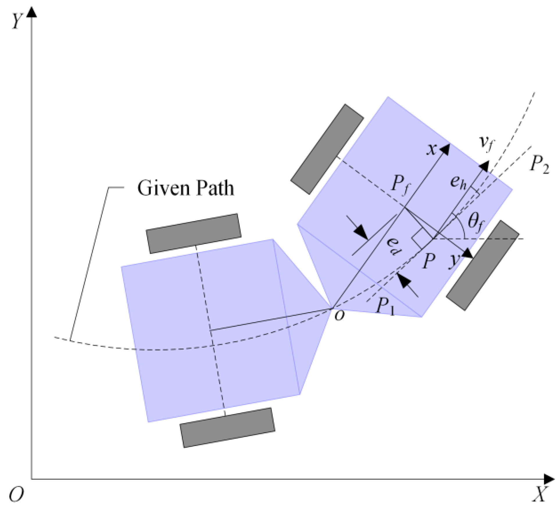
In the simulation system, the position error is decomposed into -direction error and -direction error. In order to facilitate reading, is defined as displacement error, as shown in Figure 4. is heading error.
Like the switching-MPC controller proposed by Nayl et al., the NMPC controller is a variable longitudinal velocity controller. However, in order to verify the hypothesis shown in Figure 2, simulations were divided into three groups according to three fixed longitudinal velocities. In each group of simulations, the performance of the NMPC path tracking controller was compared to that of the switching-MPC controller. In all simulations, the parameters of these two controllers were fixed, as shown in Table 3. Each group simulation had the same computer model of mining vehicles and the same given path. The given path consists of the straight line and arc, where the radius of the arc is 15 m.
3.1. Longitudinal Velocity is 2 m/s
In this group of simulations, longitudinal velocity is slow. Figure 5 shows the trajectory. Both the NMPC controller and the switching-MPC controller can drive mining vehicles to track the given path.
Figure 6 presents the articulated angle. The maximum articulated angle is 0.3895 rad and 0.4038 rad in the NMPC control system and the switching-MPC control system, respectively. In contrast, the articulated angle of the NMPC controller changes more smoothly.
Figure 7 shows the articulated angle speed. The maximum articulated angle speed is 0.1085 rad/s and 0.1400 rad/s in the NMPC control system and the switching-MPC control system, respectively. The articulated angle speed of the NMPC controller changes smoothly, but this value of the switching-MPC is chattering.
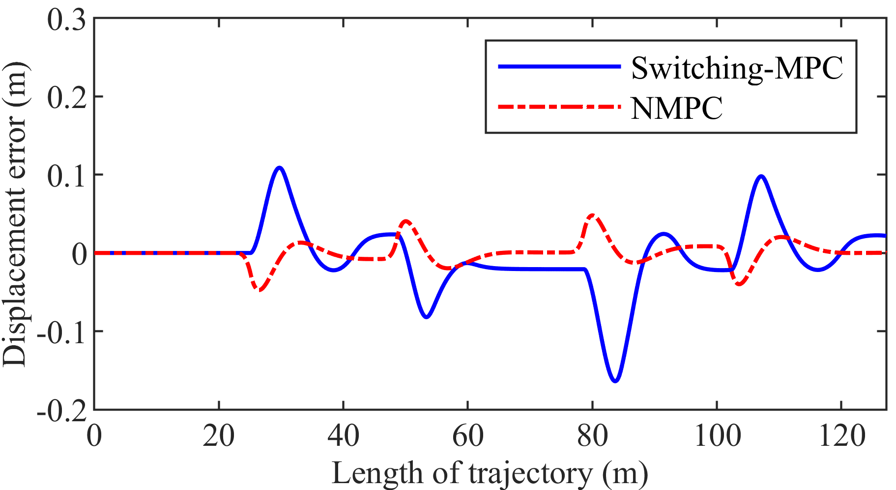
Figure 8 presents the displacement error. The maximum displacement error is 0.0480 m and 0.1638 m in the NMPC control system and the switching-MPC control system, respectively. The maximum displacement error of the NMPC controller is 70.70% smaller than that of the switching-MPC controller.
Figure 9 shows the heading error. The maximum heading error is 0.0343 rad and 0.0429 rad in the NMPC control system and the switching-MPC control system, respectively. The maximum heading error of the NMPC controller is 20.05% smaller than that of the switching-MPC controller.
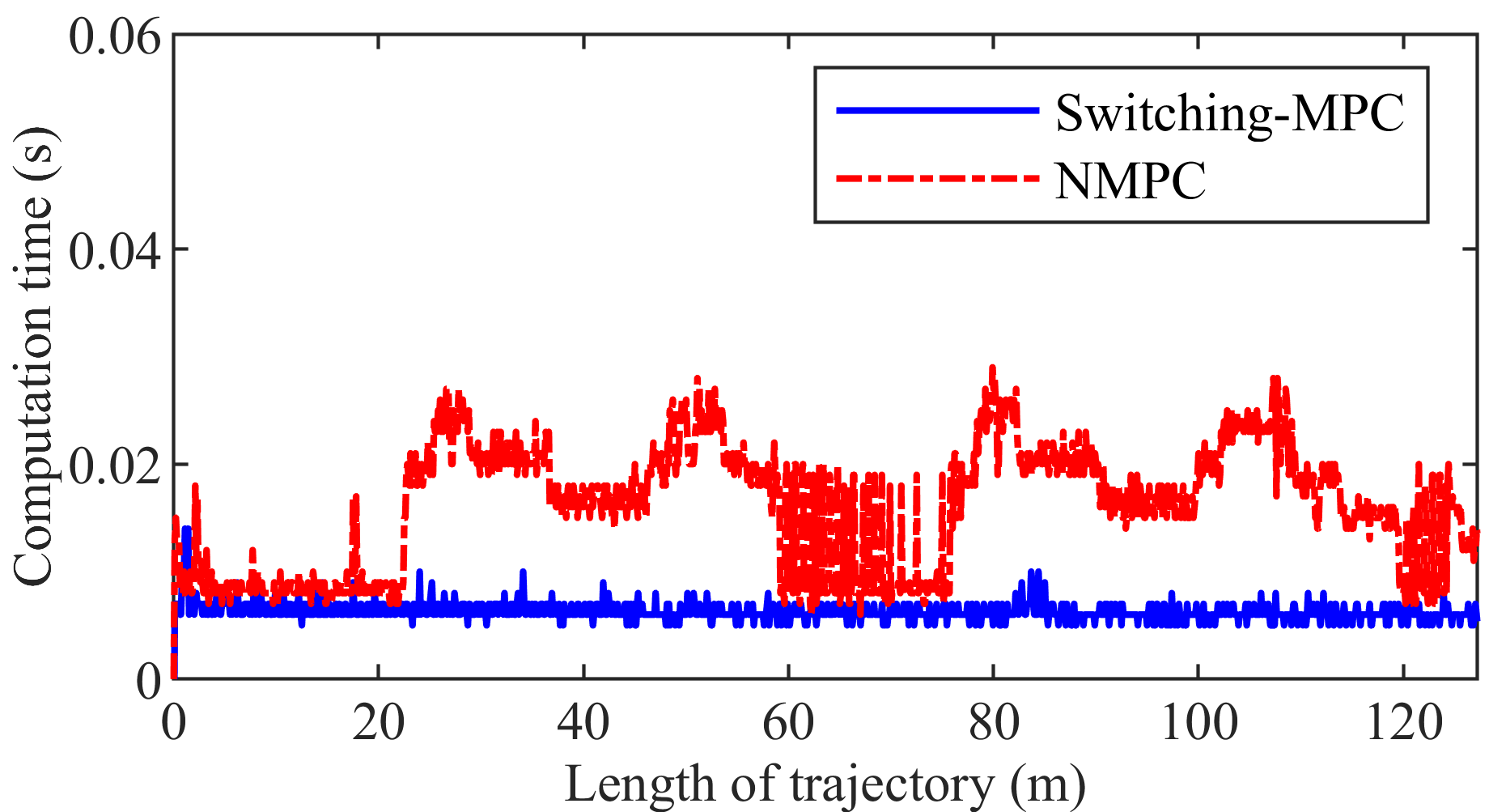
Figure 10 presents the computation time. The maximum computation time is 0.0290 s and 0.0140 s in the NMPC control system and the switching-MPC control system, respectively. Although NMPC is inferior to switching-MPC in real time, the maximum computation time of NMPC is still less than the sampling interval.
3.2. Longitudinal Velocity is 3 m/s
In this group of simulations, longitudinal velocity is faster than that of the first group simulation. Figure 11 shows the trajectory. Both the NMPC controller and the switching-MPC controller can drive mining vehicles to track the given path.
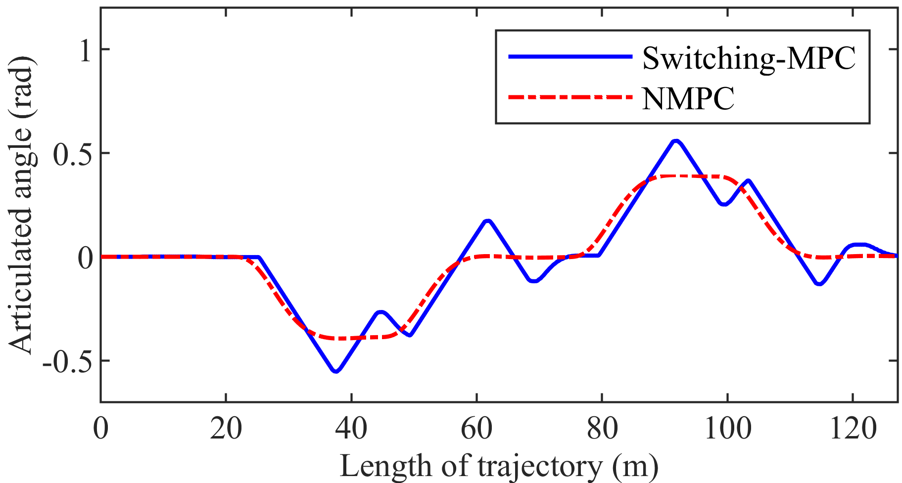
Figure 12 presents the articulated angle. The maximum articulated angle is 0.3940 rad and 0.5589 rad in the NMPC control system and the switching-MPC control system, respectively. The articulated angle of the NMPC controller changes more smoothly than that of the switching-MPC controller.
Figure 13 shows the articulated angle speed. The maximum articulated angle speed is 0.1379 rad/s and 0.1400 rad/s in the NMPC control system and the switching-MPC control system, respectively.
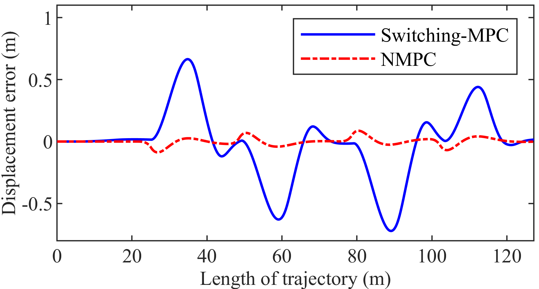
Figure 14 presents the displacement error. The maximum displacement error is 0.0874 m and 0.7217 m in the NMPC control system and the switching-MPC control system, respectively. The maximum displacement error of the NMPC controller is 87.88% smaller than that of the switching-MPC controller.
Figure 15 shows the heading error. The maximum heading error is 0.0461 rad and 0.1458 rad in the NMPC control system and the switching-MPC control system, respectively. The maximum heading error of the NMPC controller is 68.38% smaller than that of the switching-MPC controller.
Figure 16 presents the computation time. The maximum computation time is 0.0400 s and 0.0140 s in the NMPC control system and the switching-MPC control system, respectively. The maximum computation time of NMPC is less than the sampling interval.
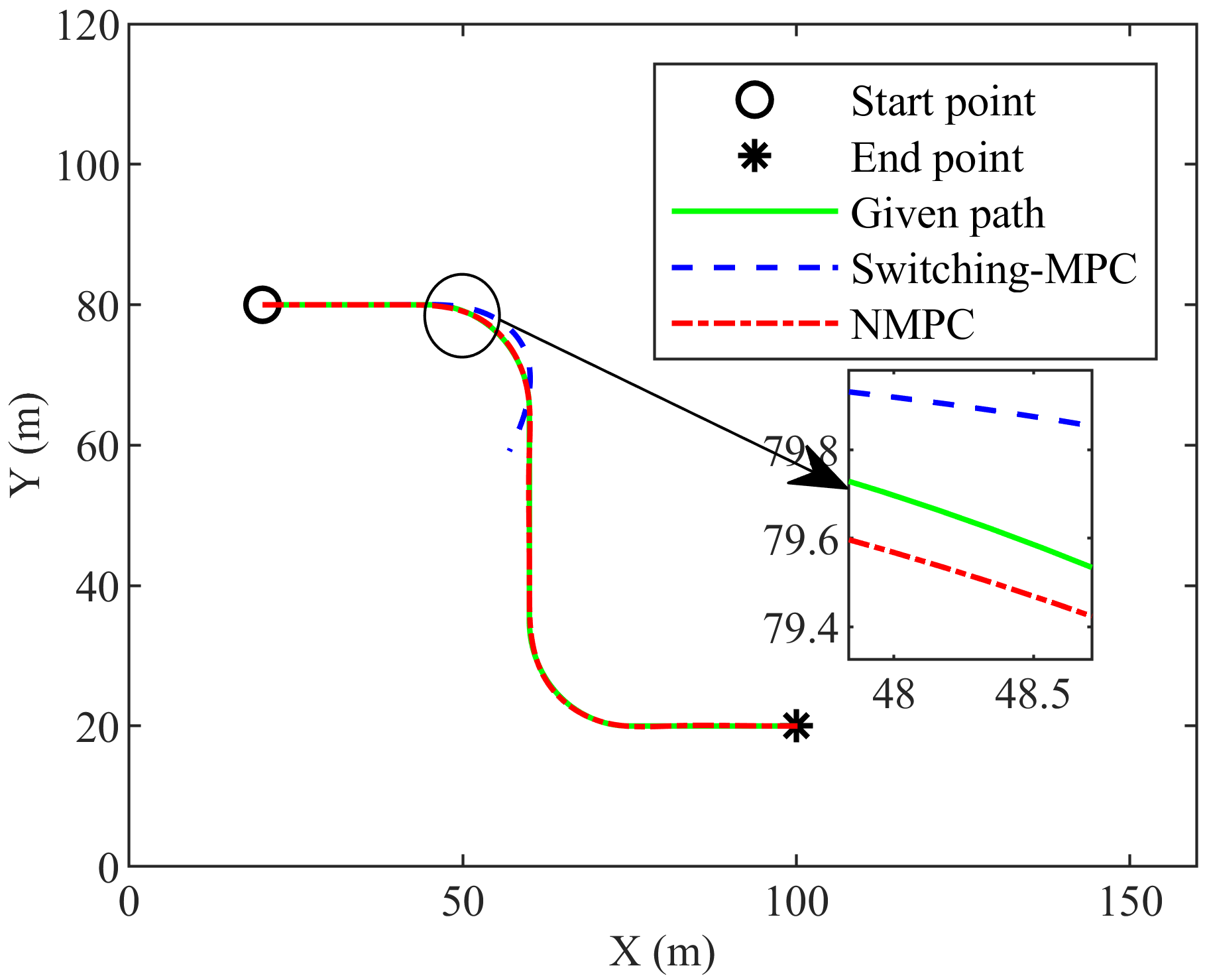
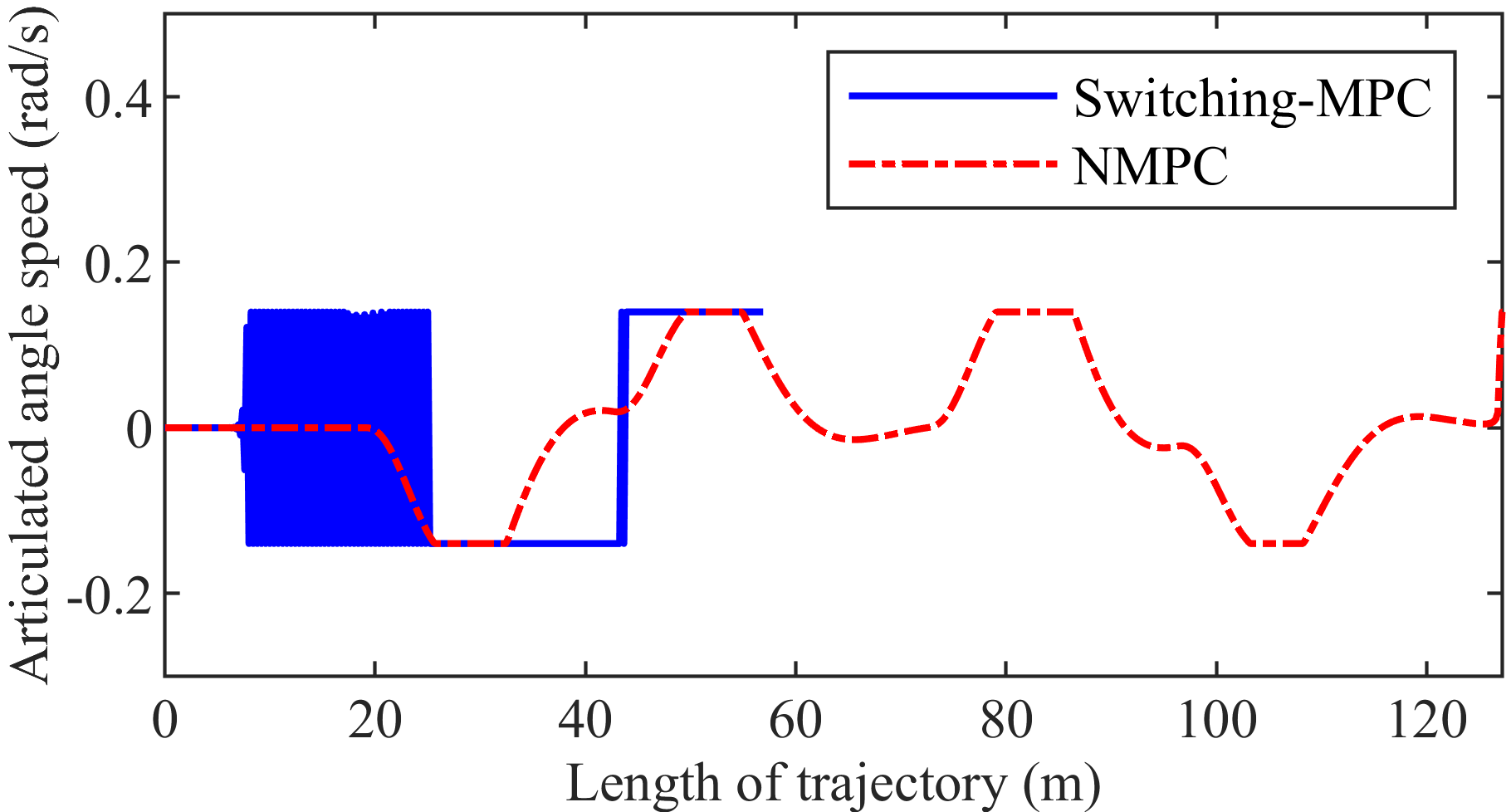
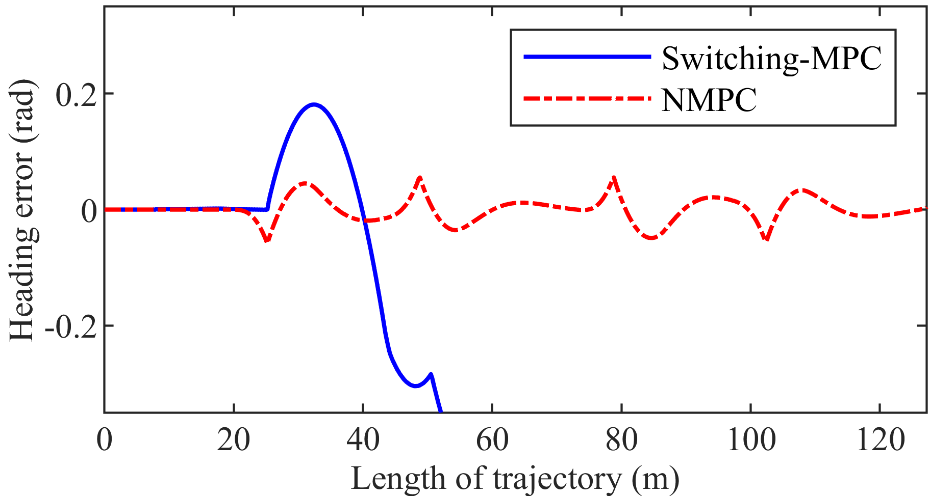
3.3. Longitudinal Velocity is 4 m/s
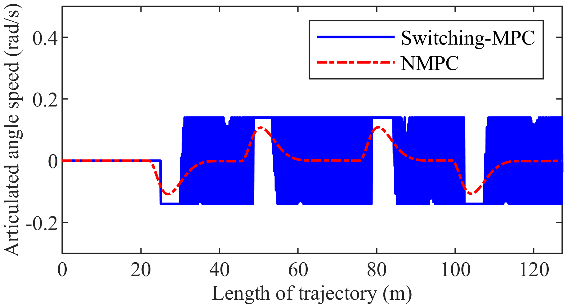
Figure 17 shows the trajectory. The NMPC controller can drive the mining vehicle to track the given path, but the switching-MPC controller cannot. Figure 18 presents the articulated angle. The maximum articulated angle is 0.4177 rad and 0.6309 rad in the NMPC control system and the switching-MPC control system, respectively. Figure 19 shows the articulated angle speed. The maximum articulated angle speed is 0.1400 rad/s in both the NMPC control system and the switching-MPC control system. Figure 20 presents the displacement error. The maximum displacement error is 0.1382 m in the NMPC control system, while the displacement error of the switching-MPC controller is divergent. Figure 21 shows the heading error. The maximum heading error is 0.0461 rad in the NMPC control system while the heading error of the switching-MPC controller is divergent. Figure 22 presents the computation time. The maximum computation time is 0.0380 s and 0.0120 s in the NMPC control system and the switching-MPC control system, respectively. The maximum computation time of NMPC is less than the sampling interval.
It can be seen from the three groups of simulations that displacement error of the NMPC controller at the longitudinal velocity of 4 m/s is 0.0256 m, which is smaller than that of the switching-MPC controller at the longitudinal velocity of 2 m/s. At the same time, in this case, heading error of the NMPC controller is 0.0032 rad larger than that of the switching-MPC. Thus, the tracking accuracy of the NMPC controller at the longitudinal velocity of 4 m/s is similar to that of the switching-MPC at the longitudinal velocity of 2 m/s.
4. Conclusions
Path tracking of articulated vehicles is one of the key technologies for mining system automation, which can reduce operators’ working time in the underground environment. For path tracking control methods, the researches of Nayl et al. prove that MPC is very useful. In order to improve the ability of mining vehicles to track complex given paths at 2 m/s or faster, we propose an NMPC-based path tracking control method for mining vehicles. By comparing the NMPC controller and the switching-MPC controller, we obtained the following conclusions.
Firstly, the NMPC controller allows mining vehicles to track the given path with less error at longitudinal velocities that are no more than 4 m/s. In the simulation presented in this paper, displacement error is not more than 0.1382 m, and heading error is not more than 0.0461 rad. Secondly, in the simulation presented in this paper, when the mining vehicle is traveling at the same longitudinal velocity, the displacement error of the NMPC controller is at least 70.70% smaller than that of the switching-MPC. Tracking accuracy of the NMPC controller is higher than that of the switching-MPC controller. Thirdly, tracking the accuracy of NMPC at the longitudinal velocity of 4 m/s is similar to that of switching-MPC at the longitudinal velocity of 2 m/s. On the basis of ensuring the same tracking accuracy, NMPC can improve the operating efficiency of mining vehicles better than switching-MPC. Besides, although NMPC is inferior to switching-MPC in real-time performance, the maximum computation time of NMPC is still less than the sampling interval. Therefore, the real-time performance of the NMPC controller can meet the requirements of path tracking.
From the perspective of science, we make the following contributions. On one hand, although NMPC has been proposed very early, its application in path tracking, especially path tracking of articulated vehicles, is not mature. The application of NMPC has not been found before in path tracking of articulated vehicles. Thus, our work is the application of NMPC in a new field. On the other hand, articulated vehicles have different motion characteristics relative to other vehicles, so the control strategies of other vehicles are difficult to use for articulated vehicles directly. In this respect, our work provides a new solution for the automation of articulated vehicles. Furthermore, though it is known that NMPC outperforms linearized MPC in some areas, what are its advantages in path tracking, especially in the path tracking of articulated vehicles? Our work is a satisfactory answer to this question.
In the future, we will focus on the longitudinal velocity control of the articulated vehicle in path tracking. The switching-MPC controller and our NMPC controller can only work at different longitudinal velocities, and they do not automatically adjust the longitudinal velocity within a large range. We also hope to add a dynamic model of the articulated vehicle in future work.
Author Contributions
Conceptualization, G.B., Q.G., and Y.M.; methodology, G.B. and Q.G.; software, G.B.; validation, G.B., and B.M.; investigation, G.B.; writing—original draft preparation, G.B.; writing—review and editing, Y.M., L.L., W.L., and Q.G.; supervision, L.L. and W.L.; project administration, L.L. and W.L.; funding acquisition, L.L., W.L., Y.M., and Q.G.
Funding
This research was funded by the National Key Research and Development Program of China, grant number 2018YFC0604403 and 2016YFC0802905, the National High Technology Research and Development Program of China (863 program), grant number 2011AA060408 and the Fundamental Research Funds for the Central Universities, grant number FRF-TP-17-010A2.
Conflicts of Interest
The authors declare no conflict of interest. The funders had no role in the design of the study; in the collection, analyses, or interpretation of data; in the writing of the manuscript, or in the decision to publish the results.
References
- Alshaer, B.J.; Darabseh, T.T.; Alhanouti, M.A. Path planning, modeling and simulation of an autonomous articulated heavy construction machine performing a loading cycle. Appl. Math. Model. 2013, 37, 5315–5325. [Google Scholar] [CrossRef]
- Alshaer, B.J.; Darabseh, T.T. Modelling and control of an autonomous articulated mining vehicle navigating a predefined path. Int. J. Heavy Veh. Syst. 2014, 21, 152–167. [Google Scholar] [CrossRef]
- Corke, P.; Ridley, P. Load haul dump vehicle kinematics and control. J. Dyn. Syst. Meas. Control 2003, 125, 54–59. [Google Scholar]
- Ji, X.; Liu, Y.; He, X.; Yang, K.; Na, X.; Lv, C.; Liu, Y. Interactive control paradigm based robust lateral stability controller design for autonomous automobile path tracking with uncertain disturbance: A dynamic game approach. IEEE Trans. Veh. Technol. 2018, 67, 6906–6920. [Google Scholar] [CrossRef]
- Andersen, H.; Zhuang, J.C.; You, H.E.; Pendleton, S.; Ang, M.H., Jr. Geometric path tracking algorithm for autonomous driving in pedestrian environment. In Proceedings of the 2016 IEEE International Conference on Advanced Intelligent Mechatronics (AIM), Banff, AB, Canada, 12–15 July 2016. [Google Scholar] [CrossRef]
- Roberts, J.M.; Duff, E.S.; Corke, P.I.; Sikka, P. Autonomous control of underground mining vehicles using reactive navigation. In Proceedings of the IEEE International Conference on Robotics and Automation, San Francisco, CA, USA, 24–28 April 2000. [Google Scholar] [CrossRef]
- Ji, J.; Khajepour, A.; Melek, W.; Huang, Y. Path planning and tracking for vehicle collision avoidance based on model predictive control with multi-constraints. IEEE Trans. Veh. Technol. 2017, 66, 952–964. [Google Scholar] [CrossRef]
- Couchman, P.; Kouvaritakis, B.; Cannon, M. LTV models in MPC for sustainable development. Int. J. Control 2007, 79, 63–73. [Google Scholar] [CrossRef]
- Barbarisi, O.; Palmieri, G.; Scala, S.; Glielmo, L. LTV-MPC for yaw rate control and side slip control with dynamically constrained differential braking. Eur. J. Control 2009, 15, 468–479. [Google Scholar] [CrossRef]
- Mousavi, M.A.; Heshmati, Z.; Moshiri, B. LTV-MPC based path planning of an autonomous vehicle via convex optimization. In Proceedings of the 2013 21st Iranian Conference on Electrical Engineering (ICEE), Mashhad, Iran, 14–16 May 2013. [Google Scholar] [CrossRef]
- Ostafew, C.J.; Schoellig, A.P.; Barfoot, T.D. Learning-based nonlinear model predictive control to improve vision-based mobile robot path-tracking in challenging outdoor environments. J. Field Robot. 2015, 33, 133–152. [Google Scholar] [CrossRef]
- Backman, J.; Oksanen, T.; Visala, A. Navigation system for agricultural machines: Nonlinear model predictive path tracking. Comput. Electron. Agric. 2012, 82, 32–43. [Google Scholar] [CrossRef]
- Marafioti, G.; Liljeback, P.; Transeth, A.A. A study of nonlinear model predictive control (NMPC) for snake robot path following. In Proceedings of the 2014 IEEE International Conference on Robotics and Biomimetics (ROBIO 2014), Bali, Indonesia, 5–10 December 2014. [Google Scholar] [CrossRef]
- Faulwasser, T.; Findeisen, R. Nonlinear model predictive path-following control. Lect. Notes. Contr. Inf. 2009, 384, 335–343. [Google Scholar]
- Yu, R.; Guo, H.; Sun, Z.; Chen, H. MPC-based regional path tracking controller design for autonomous ground vehicles. In Proceedings of the 2015 IEEE International Conference on Systems, Man, and Cybernetics, Kowloon, China, 9–12 October 2015. [Google Scholar] [CrossRef]
- Yoon, Y.; Shin, J.; Kim, H.J.; Park, Y.; Sastry, S. Model-predictive active steering and obstacle avoidance for autonomous ground vehicles. Control Eng. Pract. 2009, 17, 741–750. [Google Scholar] [CrossRef]
- Urmson, C.; Ragusa, C.; Ray, D.; Anhalt, J.; Bartz, D.; Galatali, T.; Gutierrez, A.; Johnston, J.; Harbaugh, S.; Kato, H.; et al. A robust approach to high-speed navigation for unrehearsed desert terrain. J. Field Robot. 2006, 23, 467–508. [Google Scholar] [CrossRef] [Green Version]
- Kapania, N.R.; Gerdes, J.C. Design of a feedback-feedforward steering controller for accurate path tracking and stability at the limits of handling. Vehicle Syst. Dyn. 2015, 53, 1–18. [Google Scholar] [CrossRef] [Green Version]
- Liu, C.; Zou, Z.J.; Li, T.S. Path following of underactuated surface vessels with fin roll reduction based on neural network and hierarchical sliding mode technique. Neural. Comput. Appl. 2015, 26, 1525–1535. [Google Scholar] [CrossRef]
- Hwang, C.L.; Yang, C.C.; Hung, J.Y. Path tracking of an automatic ground vehicle with different payloads by hierarchical improved fuzzy dynamic sliding-mode control. IEEE Trans. Fuzzy Syst. 2018, 26, 899–914. [Google Scholar] [CrossRef]
- Wang, R.; Yin, G.; Zhuang, J.; Zhang, N.; Chen, J. The path tracking of four-wheel steering autonomous vehicles via sliding mode control. In Proceedings of the 2016 IEEE Vehicle Power and Propulsion Conference (VPPC), Hangzhou, China, 17–20 October 2016. [Google Scholar] [CrossRef]
- Suebsaiprom, P.; Lin, C.L. Sliding mode path tracking control for fish-robot under ocean current perturbation. In Proceedings of the 2016 12th IEEE International Conference on Control and Automation (ICCA), Kathmandu, Nepal, 1–3 June 2016. [Google Scholar] [CrossRef]
- Maciejowski, J.M. Predictive Control with Constraints; Pearson education: New York, NY, USA, 2002; pp. 1–6. [Google Scholar]
- Dekker, L.; Marshall, J.; Larsson, J. Experiments in feedback linearized iterative learning-based path following for center-articulated industrial vehicles. J. Field Robot. 2019. [Google Scholar] [CrossRef]
- Tan, S.; Zhao, X.; Yang, J.; Zhang, W. A path tracking algorithm for articulated vehicle: Development and simulations. In Proceedings of the 2017 IEEE Transportation Electrification Conference and Expo, Asia-Pacific (ITEC Asia-Pacific), Harbin, China, 7–10 August 2017. [Google Scholar] [CrossRef]
- Zhao, X.; Yang, J.; Zhang, W.; Zeng, J. Sliding mode control algorithm for path tracking of articulated dump truck. Trans. CSAE 2015, 31, 198–203. [Google Scholar]
- Sasiadek, JZ.; Lu, Y. Path tracking of an autonomous LHD articulated vehicle. IFAC Proc. Vol. 2005, 38, 55–60. [Google Scholar] [CrossRef]
- Nayl, T.; Nikolakopoulos, G.; Gustafsson, T. Path following for an articulated vehicle based on switching model predictive control under varying speeds and slip angles. In Proceedings of the 2012 IEEE 17th International Conference on Emerging Technologies & Factory Automation (ETFA 2012), Krakow, Poland, 17–21 September 2012. [Google Scholar] [CrossRef]
- Nayl, T.; Nikolakopoulos, G.; Gustafsson, T. Switching model predictive control for an articulated vehicle under varying slip angle. In Proceedings of the 2012 20th Mediterranean Conference on Control & Automation (MED), Barcelona, Spain, 3–6 July 2012. [Google Scholar] [CrossRef]
- Nayl, T.; Nikolakopoulos, G.; Gustafsson, T. A full error dynamics switching modeling and control scheme for an articulated vehicle. Int J. Control Autom. 2015, 13, 1221–1232. [Google Scholar] [CrossRef] [Green Version]
- Scheding, S.; Dissanayake, G.; Nebot, E.; Durrant-Whyte, H. Slip modelling and aided inertial navigation of an LHD. In Proceedings of the International Conference on Robotics and Automation, Albuquerque, NM, USA, 25–25 April 1997; pp. 1904–1909. [Google Scholar]
- Scheding, S.; Dissanayake, G.; Nebot, E.; Durrant-Whyte, H. An experiment in autonomous navigation of an underground mining vehicle. IEEE Trans. Robot. Autom. 1999, 15, 85–95. [Google Scholar] [CrossRef] [Green Version]
- Corke, P.I.; Ridley, P. Steering kinematics for a center-articulated mobile robot. IEEE Trans. Robotic Autom. 2001, 17, 215–218. [Google Scholar] [CrossRef]
- Nayl, T.; Nikolakopoulos, G.; Gustafsson, T. Kinematic modeling and simulation studies of a LHD vehicle under slip angles. In Proceedings of the International Conference on Modelling, Simulation and Identification, Pittsburgh, PA, USA, 7–9 November 2011; pp. 344–349. [Google Scholar]
Figure 1.
Mining articulated vehicle.

Figure 2.
Predicted error and actual future errors when longitudinal velocity changes: (a) longitudinal velocity is slow; (b) longitudinal velocity is fast.
Figure 2.
Predicted error and actual future errors when longitudinal velocity changes: (a) longitudinal velocity is slow; (b) longitudinal velocity is fast.

Figure 3.
Model of articulated vehicle.

Figure 4.
Displacement error and heading error.

Figure 5.
The trajectory of the first group simulation.

Figure 6.
The articulated angle of the first group simulation.

Figure 7.
Articulated angle speed of the first group simulation.

Figure 8.
Displacement error of the first group simulation.

Figure 9.
Heading error of the first group simulation.

Figure 10.
The computation time of the first group simulation.

Figure 11.
The trajectory of the second group simulation.

Figure 12.
The articulated angle of the second group simulation.

Figure 13.
Articulated angle speed of the second group simulation.

Figure 14.
Displacement error of the second group simulation.

Figure 15.
Heading error of the second group simulation.

Figure 16.
The computation time of the second group simulation.

Figure 17.
The trajectory of the third group simulation.

Figure 18.
The articulated angle of the third group simulation.

Figure 19.
Articulated angle speed of the third group simulation.

Figure 20.
Displacement error of the third group simulation.

Figure 21.
Heading error of the third group simulation.

Figure 22.
The computation time of the third group simulation.


Table 1.
The physical meaning of parameters.
| Physical Meaning | Front Body | Rear Body |
|---|---|---|
| Axle center | ||
| Length | ||
| Velocity | ||
| Heading | ||
| Radius | ||
| Articulated point | ||
| Steering center | ||
Table 2.
Parameters of the mining vehicle.
| Parameter | Value |
|---|---|
| 2.468 m | |
| 3.439 m | |
| Range of | (0 m/s, 6 m/s) |
| Range of | (−0.698 rad, 0.698 rad) |
| Range of | (−0.14 rad/s, 0.14 rad/s) |
Table 3.
Parameters of the controller.
| Parameter | ||||||
|---|---|---|---|---|---|---|
| Value | 0.05 s | 30 | 29 | 1 |
1 is the unit matrix. The reason for setting is to consider that the default accuracy of fmincon is and the accuracy of path tracking is m. The ratio of to is based on experience, and this ratio does not significantly affect the performance of the controller when it varies over a small range.
© 2019 by the authors. Licensee MDPI, Basel, Switzerland. This article is an open access article distributed under the terms and conditions of the Creative Commons Attribution (CC BY) license (http://creativecommons.org/licenses/by/4.0/).
Share and Cite
MDPI and ACS Style
Bai, G.; Liu, L.; Meng, Y.; Luo, W.; Gu, Q.; Ma, B. Path Tracking of Mining Vehicles Based on Nonlinear Model Predictive Control. Appl. Sci. 2019, 9, 1372. https://doi.org/10.3390/app9071372
AMA Style
Bai G, Liu L, Meng Y, Luo W, Gu Q, Ma B. Path Tracking of Mining Vehicles Based on Nonlinear Model Predictive Control. Applied Sciences. 2019; 9(7):1372. https://doi.org/10.3390/app9071372
Chicago/Turabian StyleBai, Guoxing, Li Liu, Yu Meng, Weidong Luo, Qing Gu, and Baoquan Ma. 2019. "Path Tracking of Mining Vehicles Based on Nonlinear Model Predictive Control" Applied Sciences 9, no. 7: 1372. https://doi.org/10.3390/app9071372
Note that from the first issue of 2016, this journal uses article numbers instead of page numbers. See further details here.