Direct Yaw Moment Control for Enhancing Handling Quality of Lightweight Electric Vehicles with Large Load-To-Curb Weight Ratio


1
Department of Mechanical Systems Engineering, Tokyo University of Agriculture and Technology, 2-24-16 Naka-cho Koganei, Tokyo 184-0012, Japan
2
Department of Mechanics and Maritime Sciences, Chalmers University of Technology, 412 96 Gothenburg, Sweden
*
Author to whom correspondence should be addressed.
Appl. Sci. 2019, 9(6), 1151; https://doi.org/10.3390/app9061151
Submission received: 16 February 2019
/
Revised: 13 March 2019
/
Accepted: 13 March 2019
/
Published: 19 March 2019
(This article belongs to the Special Issue Multi-Actuated Ground Vehicles: Recent Advances and Future Challenges)
Abstract
:In this paper a vehicle dynamics control system is designed to compensate the change in vehicle handling dynamics of lightweight vehicles due to variation in loading conditions and the effectiveness of the proposed design is verified by simulations and an experimental study using a fixed-base driving simulator. Considering the electrification of future mobility, the target vehicle of this research is a lightweight vehicle equipped with in-wheel motors that can generate an additional direct yaw moment by transverse distribution of traction forces to control vehicle yawing as well as side slip motions. Previously, the change in vehicle handling dynamics for various loading conditions have been analyzed by using a linear two-wheel vehicle model in planar motion and a control law of the DYC system based on feed-forward of front steering angular velocity and feedback of vehicle yaw rate. The feed-forward controller is derived based on the model following control with approximation of the vehicle dynamics to 1st-order transfer function. To make the determination of the yaw rate feedback gain model-based and adaptable to various vehicle velocity conditions, this paper selects a method where the yaw rate feedback gain in the DYC system is determined in a way that the steady-state yaw rate gain of the controlled loaded vehicle matches the gain of the unloaded vehicle. The DYC system is simulated in a single lane change maneuver to confirm the improved responsiveness of the vehicle while simulations of a double-lane change maneuver with a driver steering model confirms the effectiveness of the DYC system to support tracking control. Finally, the effectiveness of the proposed DYC system is also verified in an experimental study with ten human drivers using a fix-based driving simulator.
1. Introduction
Electrification can reduce the energy consumption and increase the energy efficiency of future mobility. For road vehicles in general the energy consumption is reduced by purpose design, i.e., designing vehicles for their intended use and also by reducing losses such as aerodynamic drag. In particular, for urban mobility with moderate maximum speeds but frequent acceleration and braking, purpose design leads to the development of lightweight vehicles [1] equipped with regenerative braking system integrated with electronic stability control for energy recuperation [2] and possibly also Low Rolling Resistance (LRR) tires [3].
Even before the trend towards electromobility emerged it is generally accepted that significantly improved overall vehicle efficiency can only be obtained by reducing the vehicle curb weight itself [4]. However, lightweight vehicle designs are then facing challenges for everyday loading conditions because the driving dynamic changes significantly with large load-to-curb weight ratios [1]. Furthermore, this effect grows progressively with the reduction of the vehicle curb weight. A large load-to-curb weight ratio not only gives a significant change of the total mass but it also leads to significant changes of other important vehicle parameters [1]. Therefore, passive driving dynamics change significantly with the loading condition affecting the handling dynamics. Inevitably, this increase in load sensitivity can lead not only to changing but also a large variation in the handling dynamics which can be perceived as uncomfortable and even unsafe by the human driver [5].
Purpose design of electric vehicles for urban driving combines the advantages and peculiarities of electromobility with the use case defined by urban driving. Studies of everyday loading scenarios found that for at least one out of four trips there are at least two passengers in the vehicle [1]. Additional loading in the trunk can increase the load-to-curb weight ratio up to 40% [1]. This means that the urban use case requires high load-to-curb weight ratios for the lightweight vehicle. It also means that there is a large variation in the loading condition between individual trips, which leads to the conclusion that the lightweight vehicle cannot be designed for the average load case. The loading of the lightweight vehicle for the urban use case deteriorates not only the handling balance but also the transient response of the vehicle [6]. Of course, it is possible to use a robust chassis design approach but it comes at a cost of compromising other driving performance properties. Altogether, this provides an opportunity for new vehicle dynamics control strategies to deal with the load-sensitivity problem not only to maintain the handling balance, but also to reduce the sensitivity of the transient response [7].
The possibilities and advantages of generating an additional yaw moment by differential longitudinal forces, i.e., Direct Yaw Moment Control (DYC), on handling dynamics have been studied for a long time [8,9,10]. DYC is also called Torque Vectoring (TV) when the additional yaw moment is generated by controlling the torque distribution between left and right wheel of a driven axle. Electric vehicle powertrains based on individually controlled motors can improve the dynamic properties of the vehicle by more freely distributing the wheel torques [11]. In this regard, using in-wheel motors (IWM) provides not only a roomy interior, but also provides new dynamics control opportunities [12]. Katsuyama [13] utilized the large vertical reaction force of the IWM and the distribution of driving forces to independently control the body roll and pitch motion. Several other control objectives for DYC have been studied and experimentally verified in the research literature using model-based control approaches. Shino et al. [14] designed a DYC system with the control objective to suppress side slip angle for improving handling and stability of a small-scale electric vehicle. Fujimoto et al. [15] proposed a novel direct yaw moment control system with cascaded traction and yaw stability control. The experimental results show that the proposed control system can adapt to the road condition and attenuate the yaw rate error. Suzuki et al. [11] developed a feed-forward type of tire force distribution control together with motion control of a full drive-by-wire electric vehicle to improve vehicle stability and reduce the tire energy dissipation caused by tire slip. More recently, Pruckner [4] and Kaspar [16] studied the potential of electric single wheel drive to compensate for rear wheel drive with high rear axle load, and they also developed a prototype vehicle with a TV control concept with the main aim to show the potential of single wheel drive in general, but demonstrated that it is indeed possible to reshape the vehicle handling both in terms of steady-state understeering characteristics and transient response using TV control [17,18]. In a related study by Kaspar et al. [19], the simulation results show the robustness of the same control concept. Lightweight vehicles and large variation in loading condition were not considered in earlier research [4,16,17,18,19], but the results illustrate the potential of using DYC for this application. Kohlhuber [1,20] developed a TV feed-forward control system with an online model parameter identification approach to reduce the load sensitivity of a lightweight vehicle in terms of the overall vehicle dynamics.
Model-based control normally relies on nominal values for the internal model parameters. As stated above, for vehicle-dynamic control of lightweight vehicles the actual vehicle and tire parameters differ on a wide range between individual trips. Therefore, the nominal values should be updated for each trip to be valid. Kohlhuber [1] determined valid vehicle and tire parameters for each trip using a driving synchronous estimation method and verified the performance in multibody dynamics simulations. The developed estimation algorithm is able to estimate vehicle and tire parameters but requires minutes of journey time. The potential of using such an online model identification approach together with TV control was also presented for trip optimal feed-forward control, but neither the details regarding the TV control design nor results with the combined control and estimation design were included in the publications by Kohlhuber [1,20]. Furthermore, the performance of the closed-loop driver–vehicle system with TV control is not evaluated in earlier research [4,16,17,18,19,20].
Based on the abovementioned overview, the DYC system proposed in this paper is based on feed-forward of front steering angular velocity and a yaw rate feedback with the aim to reduce the sensitivity of the vehicle handling dynamics to the loading condition. More specifically, supported by the results of the previous study [7], the control objective of the proposed DYC system is not only the overall vehicle dynamics [18,20], but instead the objective is more focused on the transient dynamics. The feed-forward controller is derived based on model following control with approximation of the vehicle dynamics to 1st-order transfer function. The target electric vehicle with in-wheel motors generate the demanded yaw moment by transverse distribution of traction forces [11,14,21,22,23,24]. The current work is an extension of the previous study [7], with the aim to make the determination of the yaw rate feedback gain model-based and adaptable to various vehicle velocity conditions and, therefore, the yaw rate feedback gain in the DYC system is determined in a way that the steady-state yaw rate gain of the controlled vehicle matches the one in the case of unloaded vehicle. The aim is also to evaluate and verify the effectiveness of the proposed DYC system based on simulations and an experimental study using a fix-based driving simulator with a human driver in the loop.
This paper is organized as follows. Section 2 shows the sensitivity of vehicle dynamics parameters to the vehicle loading condition and then describes vehicle handling objectification and evaluation based on these parameters. The results from this section indicate the need to improve the transient and the dynamic handling performance. Section 3 describes the design of a direct yaw moment control system and a longitudinal force distributor with the overall objective to compensate for the influence of loading condition on the vehicle dynamics characteristics. In Section 4, a theoretical analysis shows the effect of the DYC input on the frequency response of the lateral dynamics. Next, in Section 5, the effectiveness of the DYC system on enhancing the vehicle handling dynamics is shown using simulation results for both a single- and a double-lane change maneuver. A 1st-order preview-prediction driver model is used to conduct the double-lane change maneuver. Then, in Section 6, an experimental study using a fixed-base driving simulator is used to evaluate the performance of the proposed DYC in a double-lane change maneuver. To evaluate the overall performance of the closed-loop driver–vehicle system the same driver model as in the previous section is used for driver parameter identification. Finally, Section 7 summarizes the paper and draws conclusions based on the simulation and driving simulator results. Based on the evaluation in the experimental study, it can be concluded that the driver model steering delay time constant are increasing with DYC which can be interpreted in the way that the subject drivers can control the vehicle to track the double-lane change in a more relaxed state.
2. Load Sensitivity Analysis
This section illustrates from a theoretical viewpoint how the loaded mass affects the vehicle handling dynamics of a lightweight vehicle. For this purpose, the lateral and yaw dynamics of the vehicle is obtained by linearizing the planar dynamics of a two-wheel vehicle model. In Section 2.3, the handling quality of the vehicle is evaluated for various loading conditions using a performance index that combines the responsiveness and controllability of the vehicle.
2.1. Vehicle Dynamics Modeling
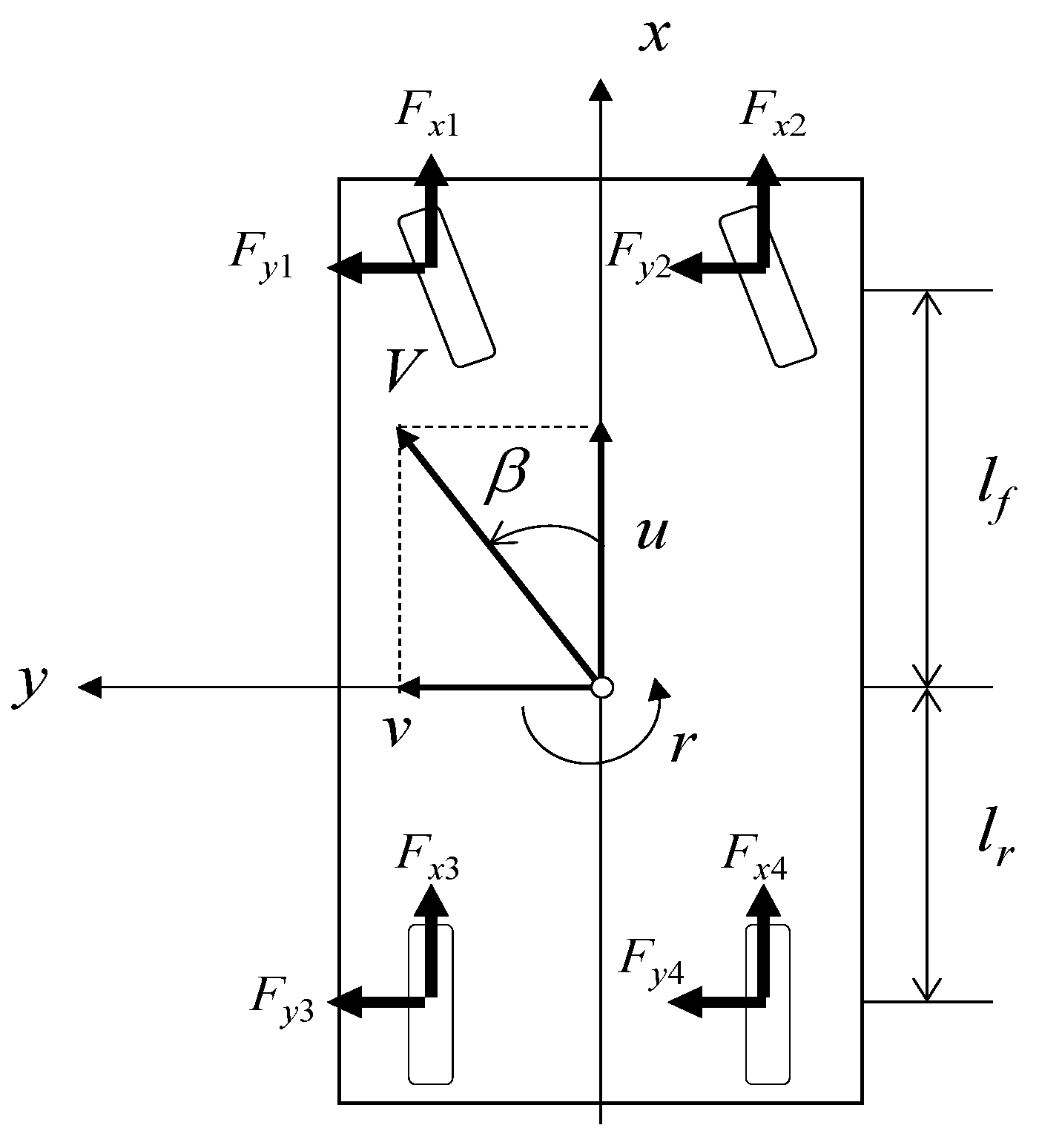
Consider the 3-DOF planar vehicle model depicted in Figure 1. Using the longitudinal velocity, , the lateral velocity, , and the yaw rate, , to describe the planar motion of the vehicle, the longitudinal, lateral, and yaw dynamics of the vehicle can be stated as
where, , indicates the vehicle mass, , the yaw moment of inertia, , the vehicle tread width, , the distance from front axle to CG, , the distance from rear axle to CG, while and indicate the longitudinal and lateral tire force at each tire, respectively, and the index refers to the number of each tire (1 = front left, 2 = front right, 3 = rear left, 4 = rear right).
Assuming low levels of lateral acceleration the lateral force characteristics of the tires can be described by a linear function of tire side slip angle. By also assuming that the influence of the tire vertical load and the longitudinal tire force are both small, the lateral tire force [25] is shown in the following equation.
where, and indicate the static vertical load and the tire side slip angle of each tire, respectively, is the tire–road friction coefficient, and is the tire cornering stiffness of the front (rear) tire. Here, it is also assumed the tire cornering stiffness is dependent on the static vertical load on each tire according to the following equation.
where, indicates the compliance steer coefficient of the front (rear) tire and and are the coefficients of the tire load dependent characteristics.
For theoretical analysis and control system design, this paper employs the linear two-wheel vehicle model in planar motion. Assuming constant vehicle velocity and small body side slip angle, the governing equations of the lateral and yaw motion can then be expressed as follows
where, is the vehicle body side slip angle, is the front steering angle, and is the additional direct yaw moment by transverse distribution of longitudinal tire forces. Here, the longitudinal tire forces are not considered when determining the lateral forces (Equation (4)). Each coefficient in Equations (6) and (7) can then be expressed as follows
2.2. Vehicle Parameters
The basic vehicle parameters for various loading conditions at the rear of the vehicle are shown in Table 1. The loaded mass, , is varied from 0 to 80 kg.
Based on the governing equations for the linear two-wheel vehicle model, Equations (6) and (7), the steady-state gains from front steering angle to the yaw rate, and body side slip angle can be calculated as follows
where, is the vehicle wheel base and the stability factor is defined as
The dependence of yaw rate and the body side slip angle gains on the vehicle velocity for the loading conditions in Table 1 are shown in Figure 2a,b, respectively. Based on Figure 2, it is found that the yaw rate gain for the loaded vehicle does not increase for low velocities but increases significantly for velocities above 40 km/h. The side slip angle increases (in negative direction) for all vehicle velocities because the loading condition shifts the center of gravity to rear and, therefore, the rear tire needs more side slip angle to generate the force needed to balance the vehicle in steady-state cornering. This theoretical analysis shows that the driver must compensate the increase in yaw rate gain by a reduction of the steering angle. The side slip angle gain is also increasing (in the negative direction).
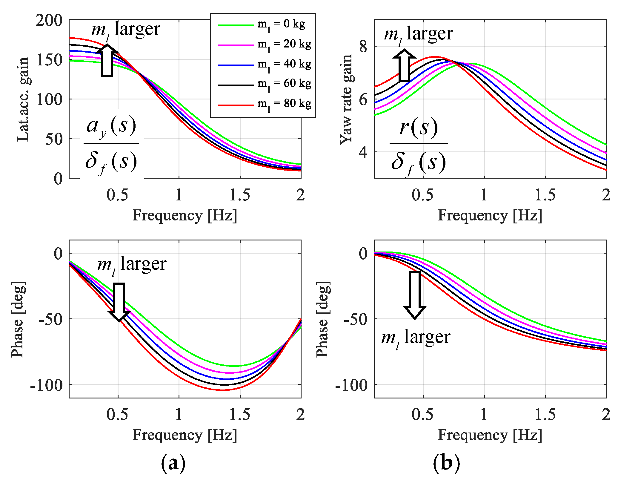
Next, the frequency response of the vehicle yaw rate and lateral acceleration to front steering angle are determined and analyzed as shown in Figure 3. Assuming no additional direct yaw moment, the Laplace transformation of the governing equations of the linear two-wheel vehicle model gives the following transfer functions from the front steering angle to the yaw rate and the lateral acceleration, respectively:
where, each parameter can be determined as follows
Based on Figure 3a,b it is found that the phase delay of both yaw rate and lateral acceleration is increasing with the loading for all frequencies. Large phase delays are negative for the handling dynamics in general but, in particular, the increase of the lateral acceleration phase delay will have a detrimental effect on the responsiveness of the vehicle. Contrary to the steady-state gains above, the gain amplitudes for higher frequencies are decreasing which is also increasing the variation of the handling dynamics.
2.3. Handling Quality Evaluation Using TB Factor
The objective and subjective handling quality evaluation is an important part of chassis control development. There are a several studies regarding a suitable methodology to consider the subjective evaluation by the driver of the vehicle responsiveness and controllability. According to Abe [25], the vehicle motion response time is an important vehicle dynamics parameter for evaluation of vehicle controllability. Lincke et al. proposed several handling quality evaluation methods [26]. Here the handling quality of the vehicle is evaluated based on the performance index called “TB factor”. This index combines the evaluation of both responsiveness (time to peak of the yaw rate response to steering wheel angle step input) and controllability (steady-state side slip angle with respect to unit lateral acceleration) into one index. According to driving simulator studies the handling quality becomes worse with increasing value of the TB factor [26].
where, the time to peak of the yaw rate response can be calculated as follows
3. Design of the Direct Yaw Moment Control System
As stated earlier, and illustrated in the previous section, there is a need to compensate for the influence of the loading condition on the vehicle dynamics characteristics using chassis control. The control design should also adapt to various velocity conditions. Here, the chassis control system is designed based on the configuration that the lightweight vehicle is equipped with in-wheel motors that can generate the demanded yaw moment. According to the objectification of handling vehicle dynamics in the previous study [7], it is important to improve the transient and the dynamic handling performance but the need to compensate for the change of steady-state cornering characteristics is less important because the driver can adapt to this change without major discomfort. Currently, constant velocity driving maneuvers are considered and it is assumed that the yaw moment demanded by the DYC system is obtained by the distribution of longitudinal tire forces on the rear axle. It is expected that the DYC system is an effective chassis control method to enhance vehicle handling performance even when the tire is not in the linear region [11,14,21,22,23,24].
To improve handling dynamics, the structure of a yaw rate model following DYC, as shown in Figure 4, consists of a feed-forward compensation with respect to the front steering angle and a yaw rate feedback compensation as the following equation.
3.1. Feed-Forward Control
Based on the Laplace transformation of governing equations of the linear two-wheel vehicle model, including the additional direct yaw moment from the transverse distribution of the longitudinal tire forces, the transfer function from front steering angle and yaw moment to yaw rate can be obtained:
where, each transfer function of vehicle yaw rate can be expressed as follows
[Transfer function with respect to front steering angle input]
[Transfer function with respect to DYC input]
Each coefficient in Equations (17) and (18) can be expressed as follows
As stated above, the primary control objective is to compensate for the deteriorated transient yaw response, i.e., small natural frequency in the loaded vehicle condition leaving the steady-state gain unaffected.
The desired yaw rate response, , to the front steering angle input is determined with a first-order lag yaw rate model:
where is the desired yaw rate gain and is the desired time constant.
To reduce the order of the transfer function of the controller, the second order transfer functions Equation (17) of the yaw rate response to front steering angle and the yaw moment are approximated to first order delay systems based on the asymptote of the yaw rate gain in the low and high frequency regions:
The feed-forward compensator to make the vehicle yaw rate follows the desired yaw rate response as indicated in Equation (19), and can be obtained using Equations (16)–(21) as follows
Next, based on the analysis in the previous study [7], the control law in Equation (22) can be further simplified as the time constant of the yaw rate response to yaw moment , which is approximately equal to the time constant of the yaw rate response to steering angle in the unloaded condition , i.e., . The steady-state yaw rate gain compensation will not be fulfilled by the feed-forward part of DYC system, i.e., . Then the resulting steering feed-forward compensation is
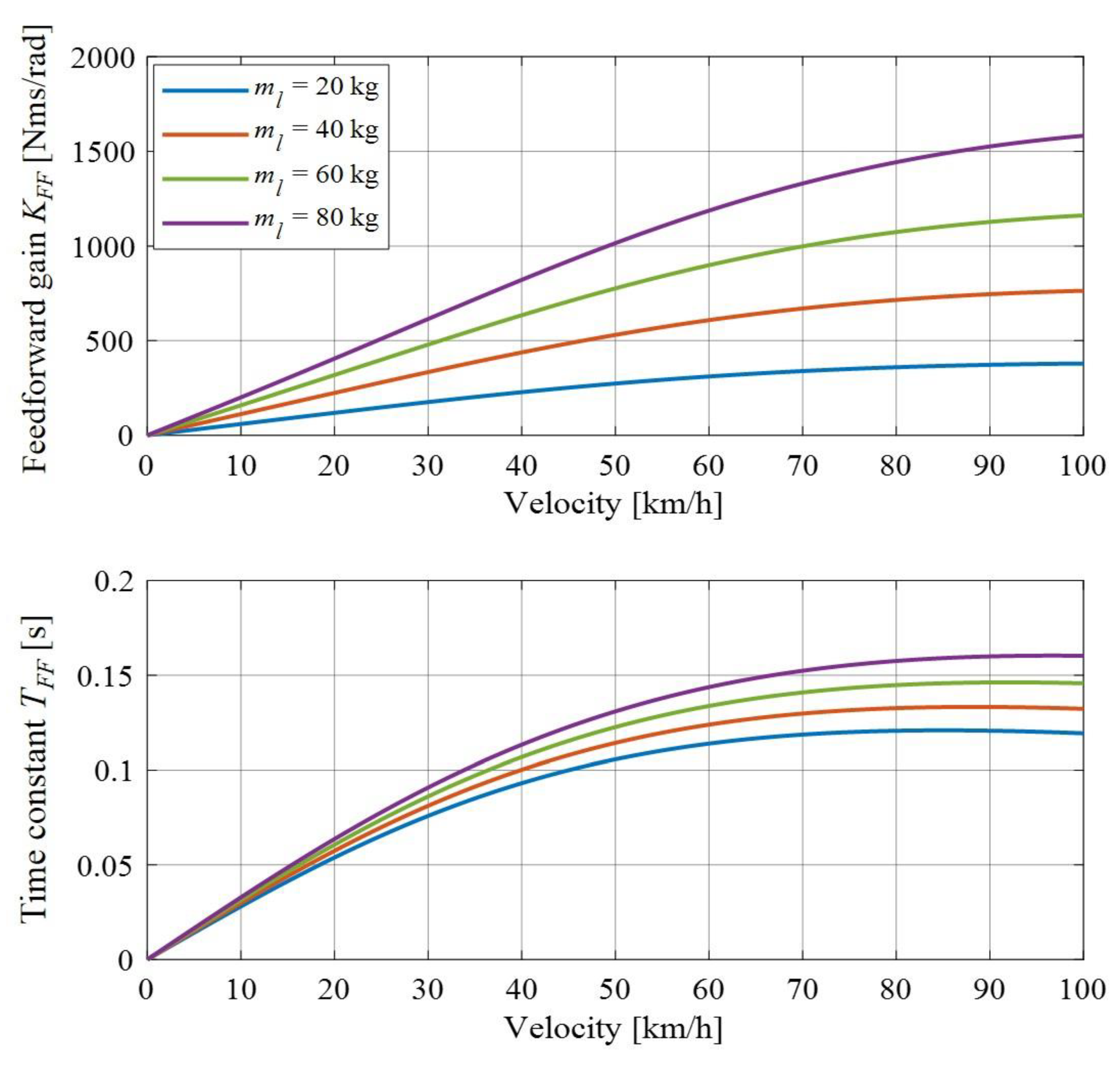
Typical values for the controller gains and their dependency on the velocity are shown in Figure 5. From the control law indicated in Equation (23), the direct yaw moment control input command is proportional to the steering angular velocity cascading with the 1st-order low-pass filter which effectively enhances the responsiveness of the vehicle yaw rate with respect to the driver steering angle input.
3.2. Feedback Control
The feedback control part of the proposed DYC system is proportional to the absolute vehicle yaw rate. There are several ways to determine the value of yaw rate feedback gain. To make the determination of the yaw rate feedback gain model-based and adaptable to various vehicle velocity conditions, this paper selects a method that the yaw rate feedback gain is determined in a way that the yaw rate gain of the controlled vehicle with respect to the steering angle matches the one in the case of unloaded vehicle. This means that DYC system will affect the vehicle motion in the way that the yaw rate gain, with respect to the steering angle, will be suppressed, resulting in improved vehicle stability. The yaw rate gain of the controlled vehicle with respect to the steering angle can be computed from the linear vehicle model as indicated in the following equation.
Next, the yaw rate gain of the unloaded vehicle as the desired vehicle yaw rate can be calculated as indicated in the following equation.
where, the coefficients and are determined from the unloaded condition vehicle parameters. By allowing the yaw rate gain in both equations to be equal to each other, the yaw rate feedback gain can be theoretically calculated as indicated in the following equation.
By substituting all coefficient values, the yaw rate feedback gain can be expressed by the vehicle parameters as the following equation.
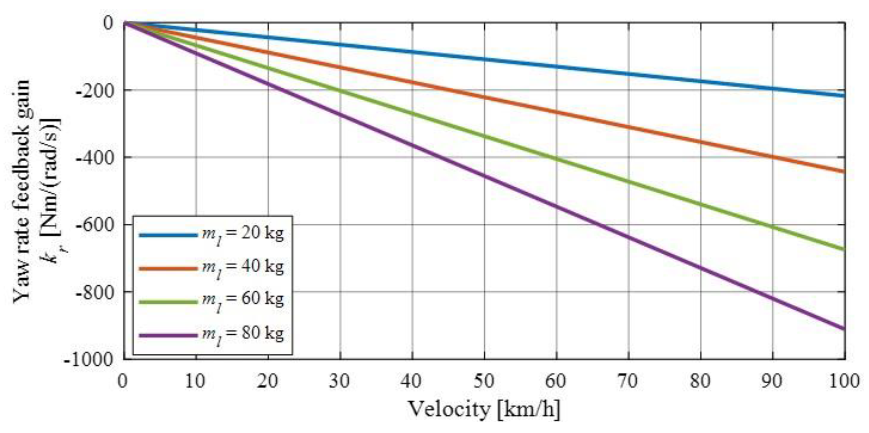
where, and indicate the vehicle stability factor, as defined by Equation (10), for loaded and unloaded vehicles, respectively. Typical values for the yaw rate feedback gain and its dependency on vehicle velocity is shown in Figure 6.
3.3. Longitudinal Force Distribution
To generate the additional yaw moment on the actual electric vehicle, the differential traction forces must be exerted on the tires of a driven axle. With the advantage of an electric vehicle with in-wheel motors, the traction forces can be differentiated easily.
Consider the case of a rear wheel driven electric vehicle with the assumption that the driving resistance is small. If the longitudinal acceleration given by driver command input to the accelerator input is given as ax, the governing equation of longitudinal dynamics Equation (1) can be expressed as
The yaw moment control input from the controller is given as follows
where lw indicates the vehicle tread width. By rearranging Equations (29) and (30), the command traction force of each tire can be calculated as follows
Rear left tire:
Rear right tire:
4. Frequency Response of Vehicle Handling Dynamics
This section shows a theoretical analysis of the effect of the DYC input on the vehicle lateral motion compared to the case without control for the loaded vehicle. As the baseline reference, the frequency response of the vehicle lateral motion for the vehicle without loading will also be shown to confirm the performance of the controller to maintain the handling dynamics of the vehicle. By substituting the equation of the DYC control law into the equations of lateral and yaw motions and then using Laplace transformation with zero initial condition, the transfer function from the front steering angle to the yaw rate, the body side slip angle, and the lateral acceleration, in the case of the vehicle equipped with the proposed DYC system, as indicated in the previous section, can be calculated as the following equations.
where each coefficient can be described as follows
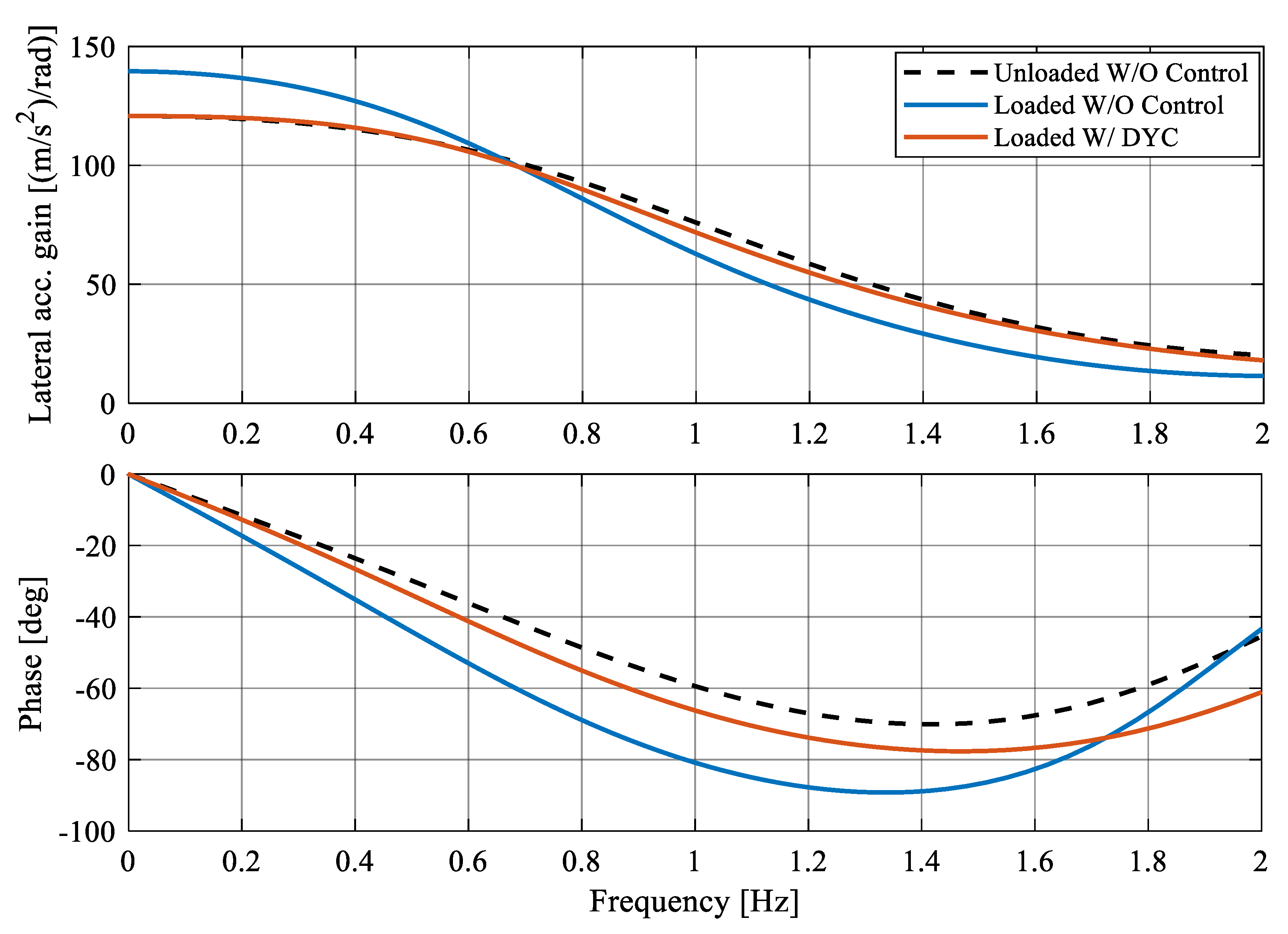
Here, if we set the values of feed-forward and feedback compensators , , and to zero, then the transfer function of the case without control can be achieved. By substituting the key vehicle dynamics parameters in the case of unloaded vehicle and the loaded vehicle, the transfer function of lateral vehicle dynamics can be obtained. As an example of theoretical analysis on the controller performance, the constant vehicle velocity is set to 80 km/h and the loading condition in the rear is 80 kg. Under this condition, the frequency responses of the yaw rate, the body side slip angle, and the lateral acceleration, with respect to the front steering angle of three cases, (1. Unloaded/without DYC, 2. Loaded/without DYC, and 3. Loaded/with DYC) are shown in Figure 7, Figure 8 and Figure 9, respectively.
As can be noticed from the frequency response plots shown in Figure 7, Figure 8 and Figure 9, in the case of the loaded vehicle without direct yaw moment control, the phase delay of the vehicle response is larger than the other cases. This corresponds to bad responsiveness of the vehicle motion with respect to the steering maneuver. Next, in the low frequency region, the steady-state gain of the vehicle response in the case of the loaded vehicle without direct yaw moment control is larger when compared with the case of the unloaded vehicle. This means that the sensitivity of vehicle motion to the steering angle is getting higher, which may lead to unstable vehicle motion in high speed region. In contrast, by applying direct yaw moment control to the loaded vehicle, the phase delay problem can be improved, and the excessive vehicle response gain to the steering angle can also be effectively compensated by the proposed DYC. In addition, it is verified that the proposed DYC can maintain the vehicle handling dynamics to be insensitive to the loading condition as it still makes the response of the loaded vehicle close to that of the unloaded vehicle.
5. Simulation Results
This section describes the effectiveness of the proposed DYC system for compensating the handling dynamics characteristics of the loaded vehicle. Simulations are conducted both for the open-loop response as well as the closed-loop maneuvering with a human driver model. Generally, the open-loop test is conducted using a predetermined steering maneuver to observe the responsiveness of the vehicle, while the closed-loop test based on a driver model is conducted to observe the handling quality of the vehicle.
5.1. Open-Loop Test
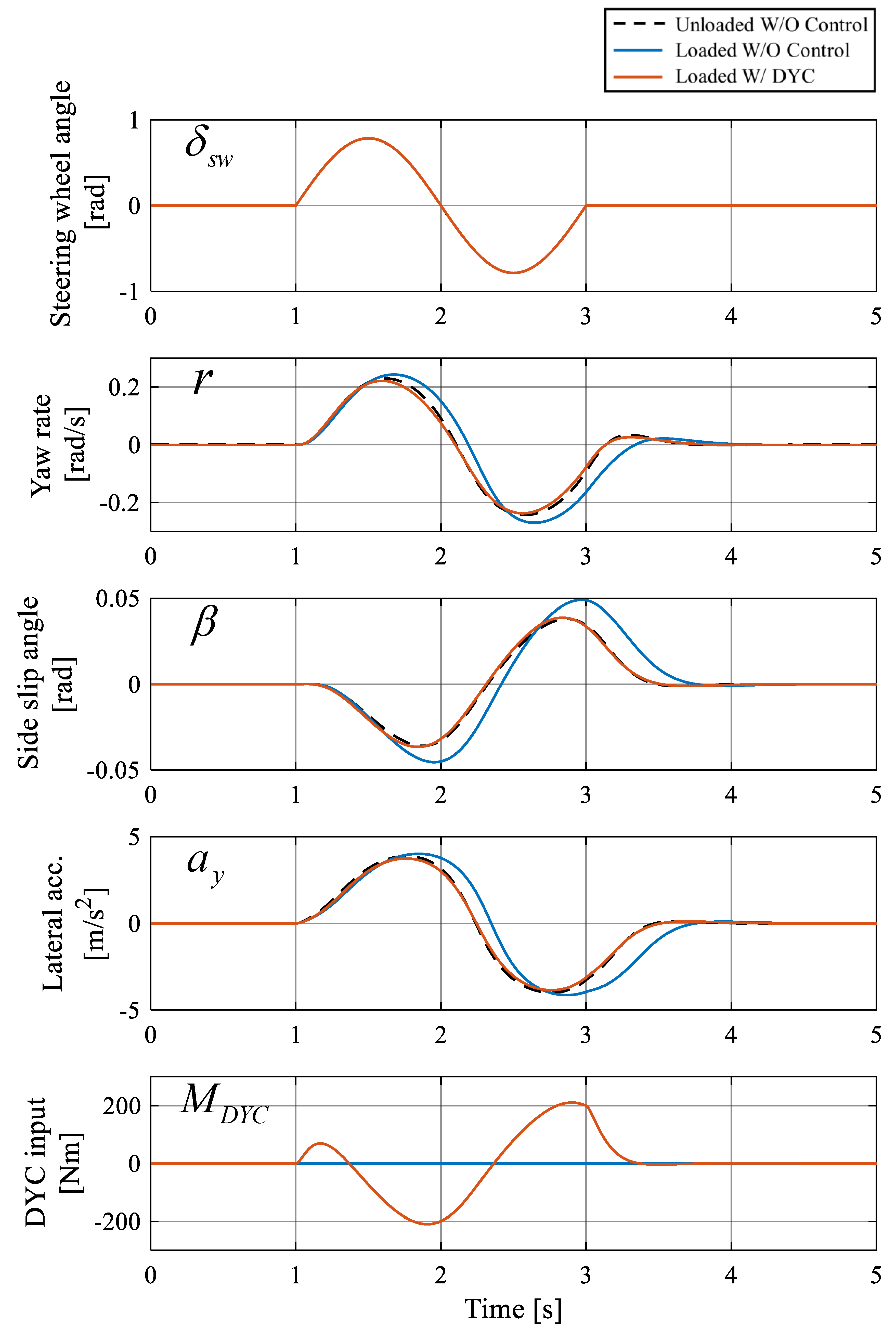
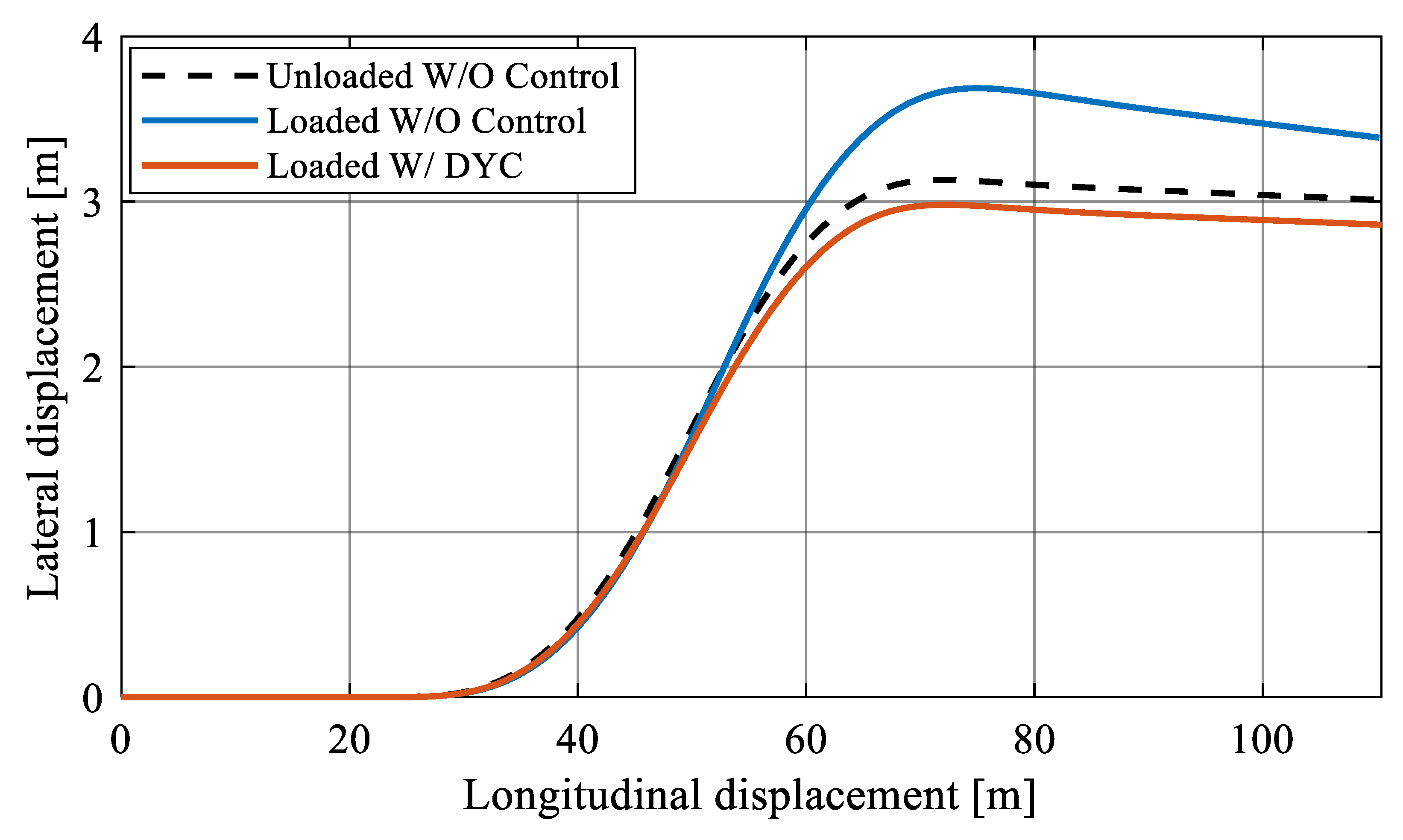
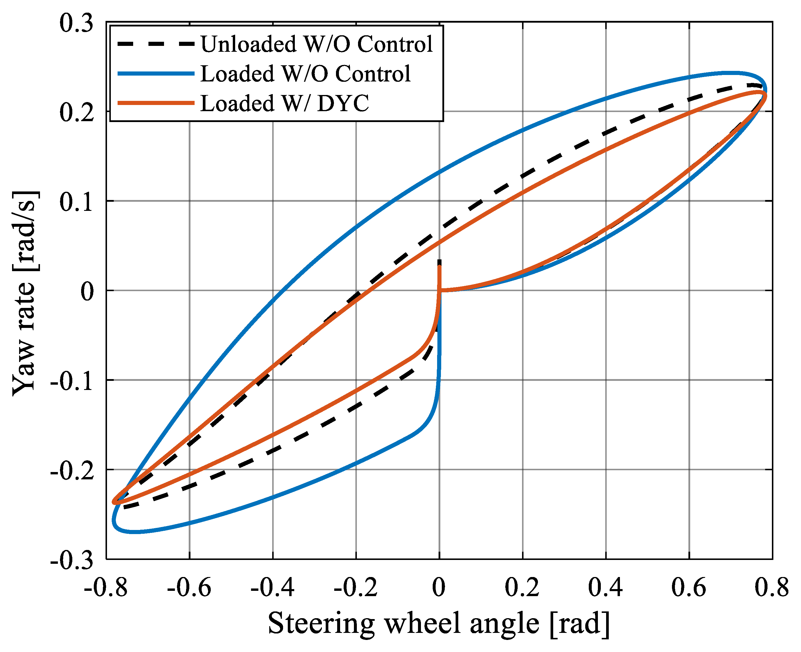
The open-loop test is conducted with a one-period sinusoidal steering maneuver with a frequency of 0.5 Hz and an amplitude of π/4 rad. The vehicle conditions are (1) unloaded vehicle without DYC (baseline), (2) 80-kg loaded vehicle without DYC, and (3) 80-kg loaded vehicle with DYC. The constant vehicle velocity is set to 80 km/h. The time history of steering wheel angle, yaw rate, body side slip angle, lateral acceleration, and yaw moment control input (DYC input) are shown in Figure 10. The vehicle trajectory is shown in Figure 11, and the Lissajous diagram of the steering wheel angle and the yaw rate is shown in Figure 12.
As can be noticed from Figure 10, the vehicle response of the 80-kg loaded vehicle without DYC becomes worse, as the phase delay of yaw rate, side slip angle, and lateral acceleration, with respect to the steering wheel angle, become larger, compared to the case of the unloaded vehicle. In addition, the gain of vehicle behavior with respect to the steering wheel angle becomes larger. In contrast, when the proposed DYC is applied, the phase delay becomes smaller in the same level as the case of unloaded vehicle and the vehicle behaves in the same manner of unloaded vehicle, thus the controller performs as expected. This means that the vehicle becomes insensitive to the loading condition. Next, as can be confirmed from the vehicle trajectory in Figure 11 and the Lissajous diagram in Figure 12, the loaded vehicle with DYC activated behaves in the same manner as the unloaded vehicle, whereas the loaded vehicle without DYC moves in different trajectory with maximum deviation of ~0.5 m compared to the unloaded vehicle. Small differences between the loaded vehicle with DYC and the unloaded vehicle can be observed here, showing that the sensitivity to the loading condition is not perfectly compensated. This is due to nonlinearity in the vehicle dynamics and tire model. This can be improved by tuning the feedback compensator in order to compensating the nonlinearity of the vehicle dynamics.
5.2. Closed-Loop Test
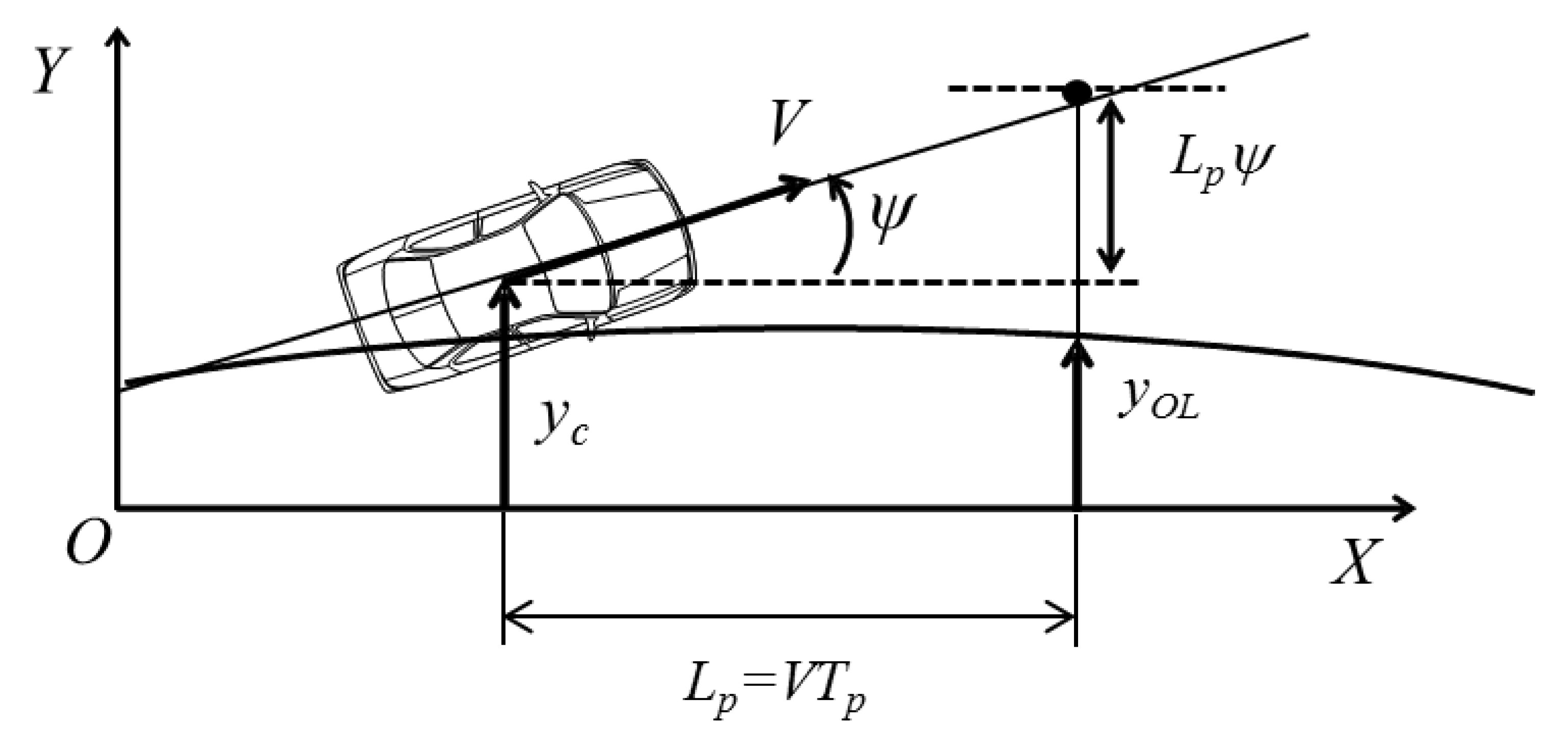
The double-lane change maneuver is used in the closed-loop test to show the effectiveness of the proposed DYC system with human driver model in the loop. A 1st-order preview-predictive driver steering model is used to conduct the lane change maneuver, see Figure 13. The driver model in lane tracking control can be expressed as follows
where, denotes the driver corrective steering gain, denotes the driver model steering delay time constant, denotes the desired preview lateral displacement, denotes the current vehicle lateral displacement, denotes the driver model predictive time, and denotes the current vehicle yaw angle with respect to the desired lane.
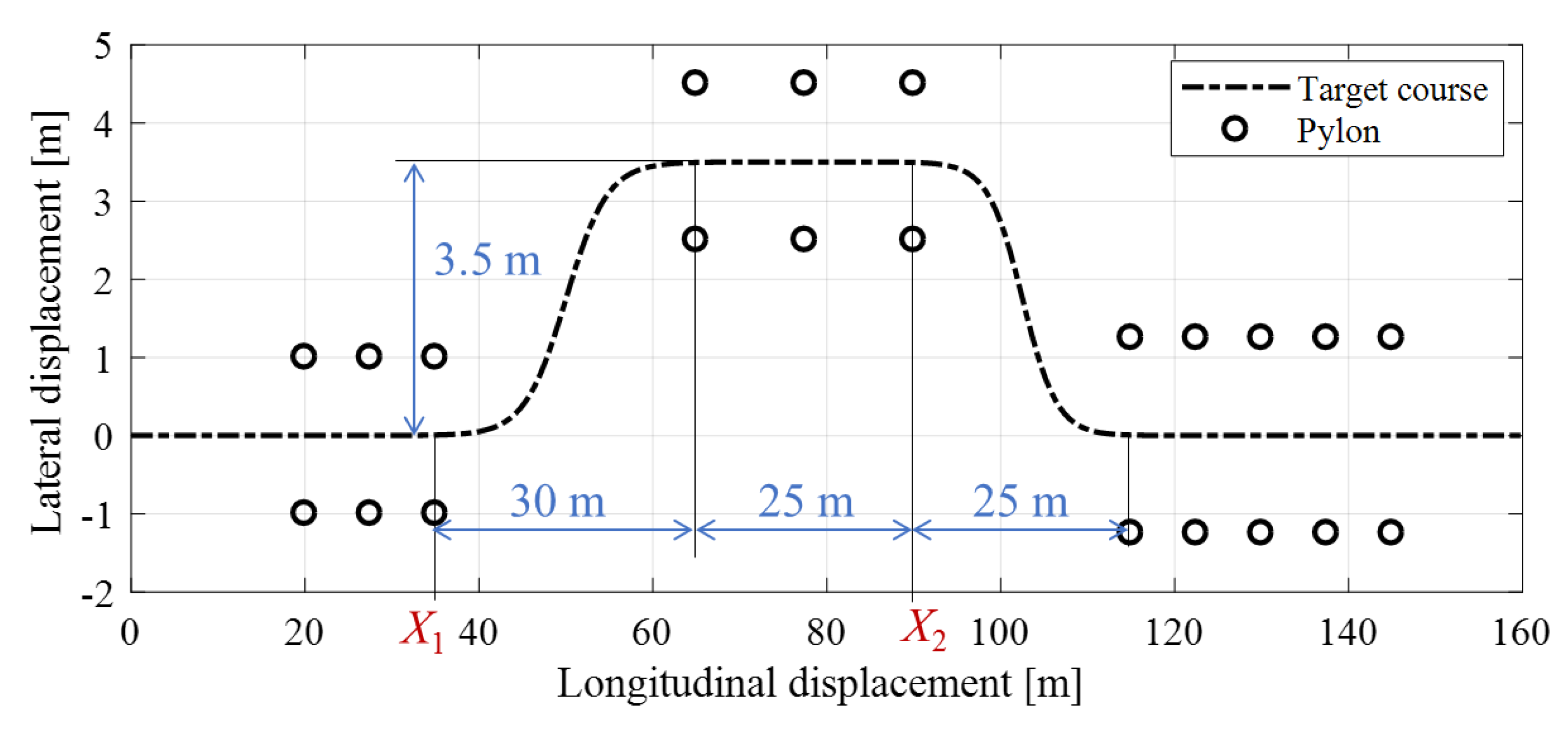
The driver model with the control law (36) is used to track a target course. The target course can be expressed as the following equations, and the plot of the course is shown in Figure 14.
where, and are the positions where the lane change is conducted at the first half and the second half, respectively. Here, in the simulations, is set to 35 m and is set to 90 m.
The simulations are conducted in same three conditions as in the previous section. The loading conditions, control conditions, and the parameters of the driver model are summarized in Table 3. The vehicle velocity is 80 km/h constant. The driver model parameters are set in the way that the resulted vehicle trajectory of all three conditions are almost the same, considering the adaptation behavior of the driver according to McRuer crossover model [27]. The steering gain, , and the driver steering delay time constant, , are set to smaller values in the case of loaded vehicle without DYC. According to Abe’s findings [25], smaller values of driver steering delay time constant mean that the driver has to control the vehicle along the target course in a more stressful manner corresponding to the lower handling quality evaluation.
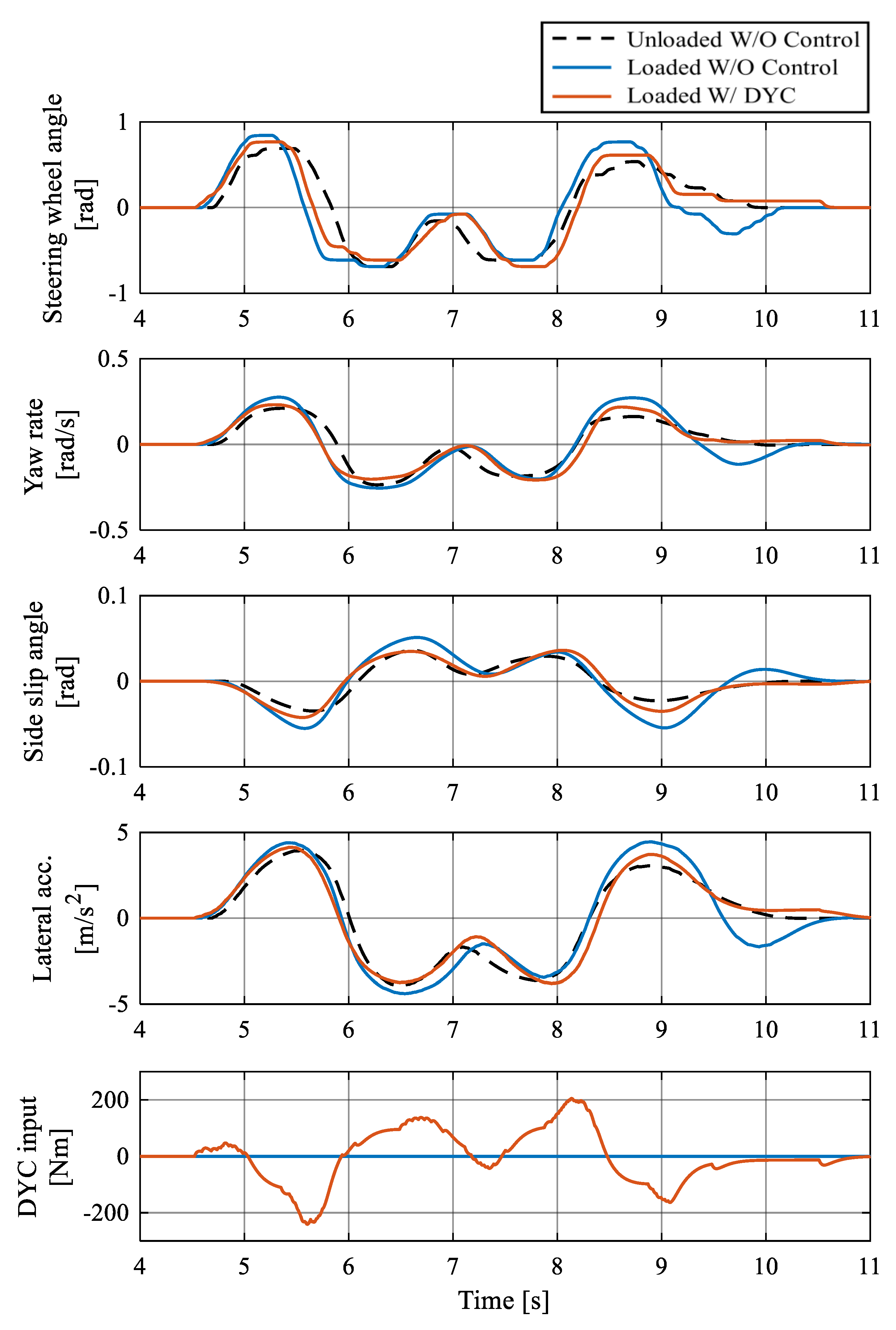
The time history of the steering wheel angle, yaw rate, body side slip angle, lateral acceleration, and yaw moment control input are shown in Figure 15. The vehicle trajectory and Lissajous diagram of the steering wheel angle and yaw rate are shown in Figure 16 and Figure 17, respectively.
As can be noticed from Figure 15, in the case of the loaded vehicle without DYC, the overall amount of steering wheel angle required for the maneuver becomes larger, the stability of the vehicle becomes worse and, as seen in the previous section, the damping behavior of the vehicle is also worse. This implies the difficulty in vehicle course tracking control in the case of loaded vehicle. On the other hand, the proposed DYC can keep the vehicle behavior (Figure 15) as well as the vehicle trajectory, as shown in Figure 16, during the double-lane change maneuver to be almost the same as the unloaded vehicle (baseline condition), which means that the vehicle with DYC is insensitive to the loading condition. Finally, as can be noticed from the Lissajous diagram in Figure 17, in the case of loaded vehicle without DYC, a large steering wheel angle is needed to track the course. When compared with the case of unloaded vehicle and the case of loaded vehicle with DYC, the residual yaw rate of loaded vehicle without DYC when the steering wheel angle is back to the neutral position is large and there are many large whirls in the diagram of loaded vehicle without DYC, which corresponds to more difficulty in controlling the vehicle to track the target double-lane change course.
6. Experimental Study Using a Driving Simulator
This section describes the experimental study of the proposed DYC for enhancing handling dynamics in a double-lane change maneuver using a fixed-base driving simulator.
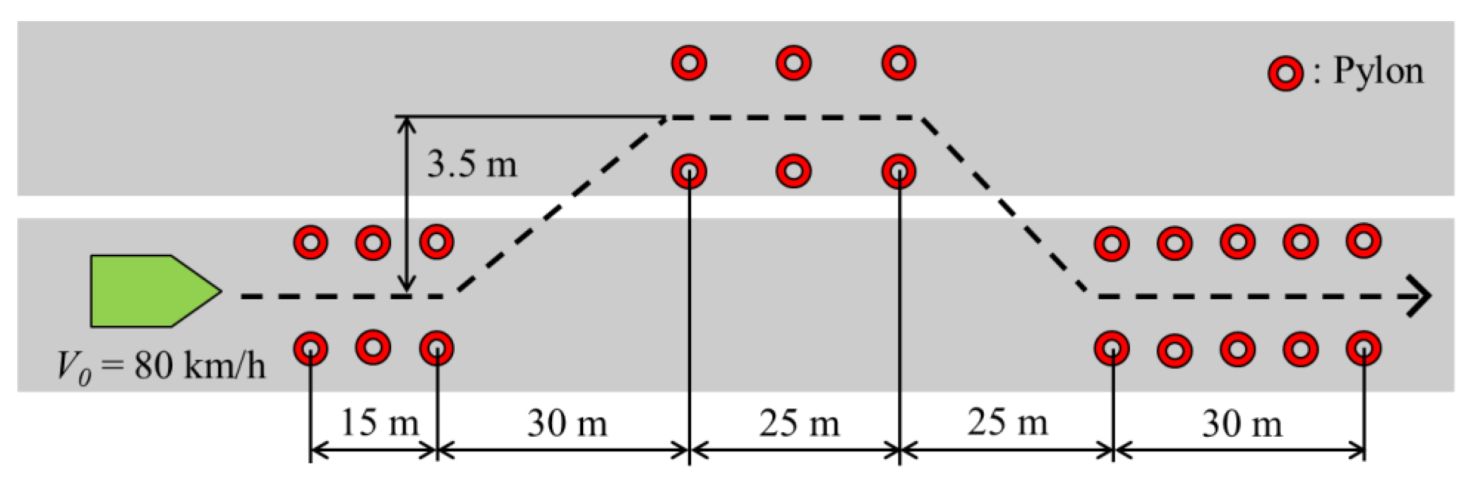
6.1. Experimental Condition
The double-lane change course shown in Figure 18, which is equivalent to emergency maneuver for collision avoidance, is used for conducting the experiment. The vehicle velocity is set to 80 km/h constant. Ten drivers were employed to drive through the set driving course and evaluate the handling quality of the vehicle in the case of (1) unloaded vehicle condition, again as a baseline, (2) without control in 80-kg loaded vehicle condition, and (3) with the proposed DYC system in 80-kg loaded vehicle condition. The software IPG Carmaker® is used to visualize the vehicle motion simulation.
6.2. Evaluation Method
The key performance indicator for the system validation is proposed in two categories. First, the evaluation indicator related to the vehicle collision avoidance performance—EAPI (Emergency Avoidance Performance Index)—was used [28]. Next, to evaluate the overall performance of the closed-loop driver–vehicle system, the driver model parameter identification method was used [25].
● Emergency Avoidance Performance Index, (EAPI):
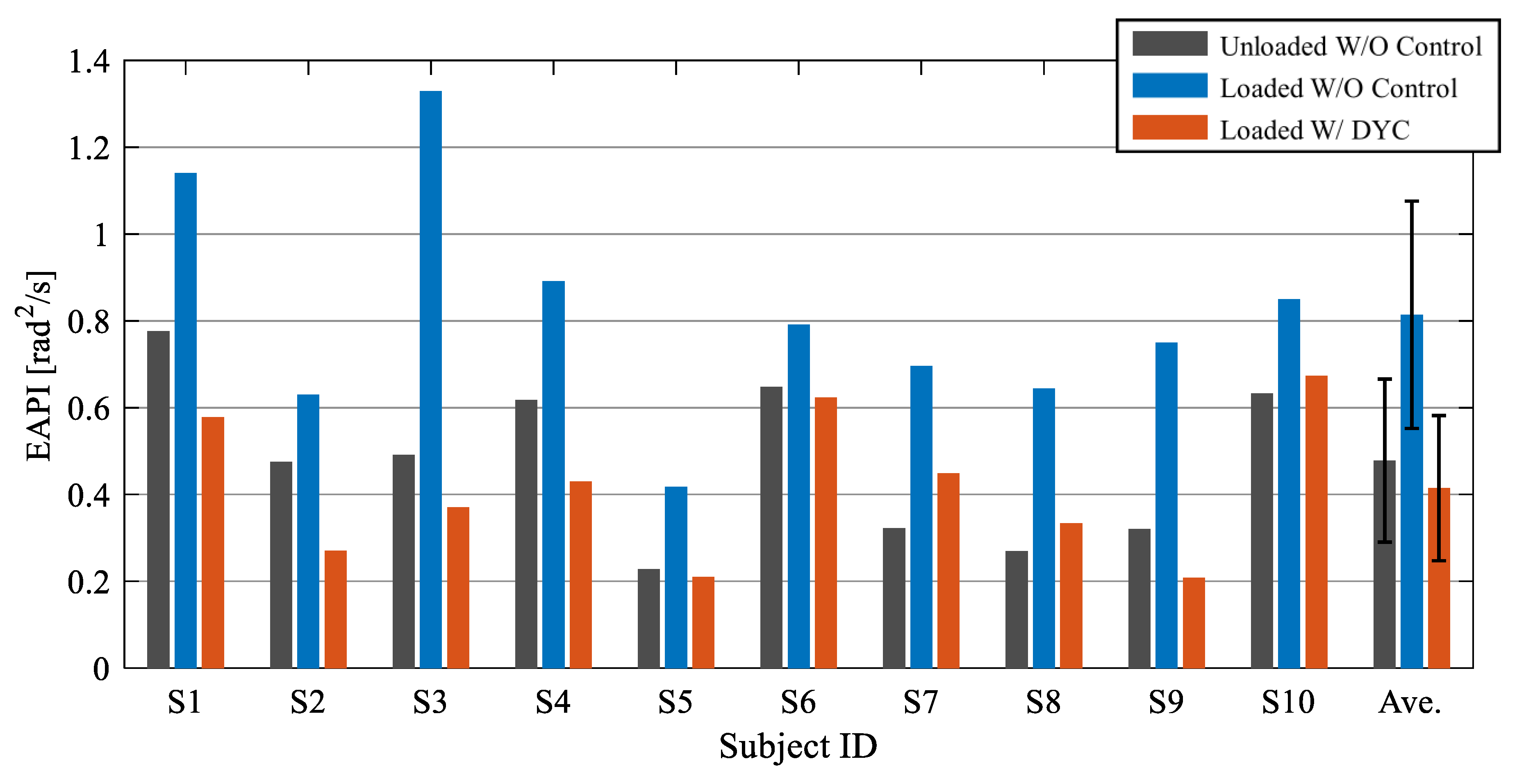
Here, the index called EAPI is determined as the area which is integrated along the curve of steering angle with respect to the yaw rate. It is generally known that the better the vehicle handling quality, the smaller the value of EAPI [28].
● Driver model steering operation 1st-order delay time constant [25]:
Generally the driver model parameter is affected by the vehicle dynamics characteristics, as the driver has adaptation characteristics according to McRuer crossover driver model description [28]. If the vehicle has good responsiveness with respect to the steering angle, the driver can be in a relaxed mood and his/her time constant increases. On the other hand, if the vehicle has bad responsiveness, the driver has to concentrate to control the vehicle; hence the handling quality from the driver’s viewpoint deteriorates. Here, the paper will use the identified parameter in a specific driving scenario to discuss about the handling quality in a quantitative way. The driver model steering operation delay time constant can be identified from the measured data of the lane change experiment. The procedure of the calculation of the parameter can be expressed as follows.
From Equation (36), the relationship between the driver steering wheel angle and the vehicle motion can be rewritten as follows
Here, from the measurement data of steering wheel angle , the lateral displacement , the constant vehicle velocity , the vehicle yaw angle , and the deviation between the actual steering wheel angle and the predicted steering wheel angle from the vehicle motion exists as the following equation.
However, the parameters , , and can be set to minimize this deviation, the parameter set which gives the minimum steering deviation is treated as the driver individual parameter set. Take the Inverse Laplace transformation of Equation (40), the following expression can be obtained.
Next, the following cost function , as the integral square of the deviation of the steering wheel angle with respect to the predicted value, is set to identify the driver model parameters , , and .
Then, by the following calculation process, the driver model parameters , , and are determined to minimize the cost function .
where, the matrices and are calculated from the collected measurement data in discrete form as follows
6.3. Results
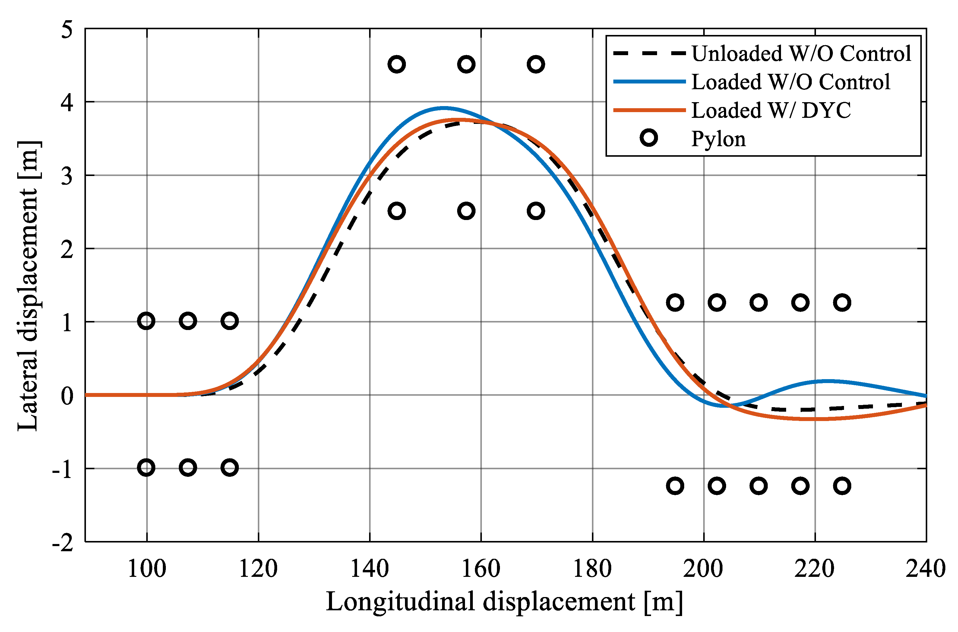
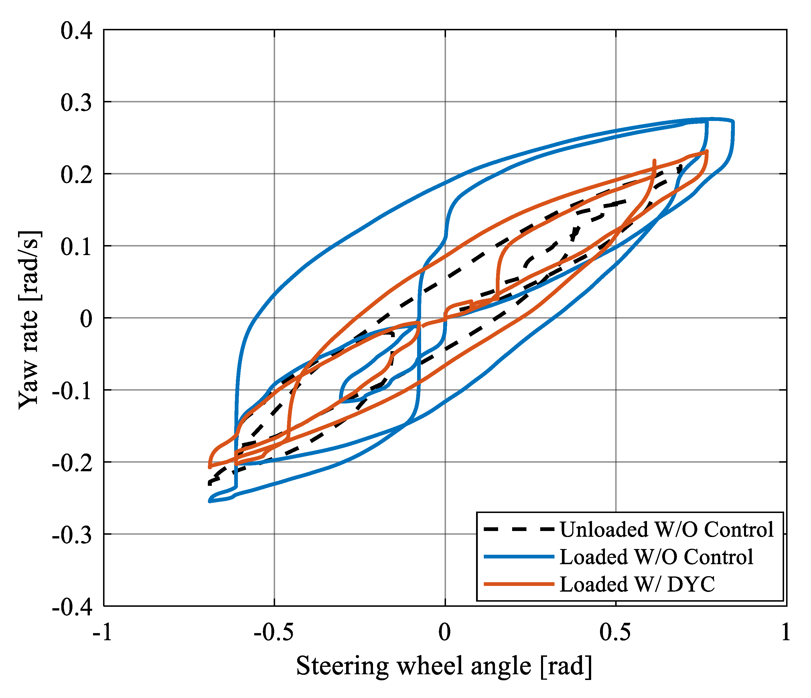
As a representative example of the driving experiment, Figure 19 shows the time history result of double-lane change maneuver in the case of the unloaded vehicle and the loaded vehicle without and with the DYC system. Figure 20 shows the trajectory of vehicle, and Figure 21 shows the Lissajous diagram of the steering wheel angle and the yaw rate. In the case of the loaded vehicle without DYC, it is difficult for the drivers to control vehicle to track the lane change path as the corrective steering operations are large and the vehicle stability is worse, especially in the latter half of the maneuver. With the DYC system, the vehicle stability is significantly improved and the driver can control the vehicle to track the path in the same manner as with the unloaded vehicle. This verifies that the proposed DYC can modify the steering response of the loaded vehicle to be similar to the response of the unloaded vehicle. These results show that the handling dynamics with the DYC system is less sensitive to the loading condition and, consequently, the handling quality is also improved.
6.4. Discussions
In this subsection, the validation of vehicle handling quality improvement in terms of the vehicle dynamics, as indicated by the key performance indicator called EAPI (Emergency Avoidance Performance Index) and the driver model parameter, as the driver steering operation delay time constant, , are discussed.
As can be noticed from Figure 22, it is found that the values of EAPI of all subject drivers become significantly smaller in the case of the loaded vehicle with DYC compared to the case of without DYC. Comparing the values in the case of the unloaded vehicle (baseline) and the case of DYC for the loaded vehicle, the values of EAPI became smaller or are maintained in the same level when the proposed DYC is applied.
As shown in Figure 23, the value of the driver steering delay time constant of the subject drivers, except for driver S3, is larger in the case of the loaded vehicle with DYC compared to the case of without DYC. This can be interpreted in the way that in the case of the loaded vehicle without control, the subject drivers controlled the vehicle in a stressful manner to trace the double-lane change path. On the other hand, when the proposed DYC is applied, the driver could control the vehicle to trace the double-lane change path in a more relaxed state, as the vehicle handling quality is effectively enhanced by the proposed DYC from the objectification method based on the driver model.
7. Conclusions
This paper first illustrates the change of handling dynamics of a 500-kg class lightweight vehicle under various loading conditions. It is shown that loading at the rear end of the vehicle does not affect the handling dynamics much at low speeds, but for velocities above 40 km/h, the handling dynamics are affected; steady-state gain of yaw rate and lateral acceleration became higher and the responsiveness and controllability in the transient state became worse, as indicated by the TB factor performance index [26]. A Direct Yaw Moment Control (DYC) system is proposed to make the loaded vehicle cohere to the response of the unloaded vehicle. The theoretical analysis of the effect of the DYC system confirms that the increase of the steady-state gain and the phase delay seen for the loaded vehicle is reduced significantly by the DYC system. In a similar way, the simulations of the single lane change maneuver confirms the improved responsiveness of the vehicle while the simulations of the double-lane change maneuver using a 1st-order preview-predictive driver steering model confirms the effectiveness of the DYC system to support tracking control. Altogether, it is verified in simulations that the DYC can enhance the vehicle handling dynamics of the loaded vehicle. Furthermore, based on the evaluation in the experimental study of the double-lane change maneuver with human driver in the loop, it is concluded that the collision avoidance performance, measured by the key performance indicator EAPI, is maintained at the same level for the loaded vehicle with DYC compared to the unloaded vehicle. In the same way, when the proposed DYC is applied, the human driver can control the vehicle to trace the double-lane change path in a more relaxed state compared to the case without DYC, indicated by an increase of the estimated driver model steering time delay constant.
In future work, the performance sensitivity of the developed DYC system to uncertainties in the internal vehicle model parameters will be investigated and the necessary countermeasures will be implemented. The performance of the DYC system in other driving context will also be investigated, e.g., the combination of the DYC system with regenerative braking when maneuvering during tight curve cornering which requires large lateral acceleration and simultaneous speed control. The long term ambition is to implement the DYC system in an experimental vehicle to perform testing at the proving ground.
Author Contributions
Conceptualization, P.R.; Formal Analysis, P.R. and M.L.; Funding Acquisition, P.R.; Methodology, P.R. and M.L.; Software, S.D. and M.L.; Supervision, P.R.; Validation, S.D.; Visualization, S.D.; Writing—Original Draft, P.R. and M.L.; Writing—Review & Editing, M.L.
Funding
This research was funded by the Institute of Global Innovation Research at Tokyo University of Agriculture and Technology (TUAT).
Acknowledgments
We thank Roman Henze, Institute of Automotive Engineering, Technische Universität Braunschweig, Germany for assistance with the handling objectification and valuable comments regarding the same.
Conflicts of Interest
The authors declare no conflict of interest.
References
- Kohlhuber, F.; Lienkamp, M. Load problem of lightweight electric vehicles and solution by online model adaptation. In Proceedings of the 5th International Chassis Tech Plus Symposium 2014, Munich, Germany, 24–25 June 2014; Pfeffer, P.E., Ed.; Springer Vieweg: Wiesbaden, Germany, 2014; pp. 281–302. [Google Scholar] [CrossRef]
- Ólafsdóttir, J.M.; Lidberg, M.; Falcone, P.; van Iersel, S.; Jansen, S. Energy Recuperation in Fully Electric Vehicles Subject to Stability and Drivability Requirements. In Proceedings of the 11th International Symposium on Advanced Vehicle Control (AVEC’12), Seoul, Korea, 9–12 September 2012. [Google Scholar]
- Kuwayama, I.; Matsumoto, H.; Heguri, H. Development of a Next Generation-Size Tire for Eco-Friendly Vehicles. In Proceedings of the 4th International Munich Chassis Tech Plus Symposium 2013, Munich, Germany, 13–14 June 2013; Springer Vieweg: Wiesbaden, Germany, 2013; pp. 623–644. [Google Scholar]
- Pruckner, A.; Kaspar, S.; Stroph, R.; Grote, C. Vehicle Dynamics per Software—Potentials of an Electric Single Wheel Drive. In Conference on Future Automotive Technology, Proceedings of the Conference on Future Automotive Technology, Munich, Germany, 7 December 2012; Lienkamp, M., Ed.; Springer Vieweg: Wiesbaden, Germany, 2013. [Google Scholar] [CrossRef]
- Apel, A.; Mitschke, M. Adjusting Vehicle Characteristics by Means of Driver Models. Int. J. Veh. Design 1997, 18, 583–596. [Google Scholar] [CrossRef]
- Hosono, T.; Takekoshi, K.; Shiiba, T. Robust handling performance against weight variation focused on transient region. In The Dynamics of Vehicles on Roads and Tracks: Proceedings of the 24th Symposium of the International Association for Vehicle System Dynamics (IAVSD 2015), Graz, Austria, 17–21 August 2015; Rosenberger, M., Plöchl, M., Six, K., Edelmann, J., Eds.; CRC Press: London, UK, 2016. [Google Scholar] [CrossRef]
- Raksincharoensak, P.; Lertsilpachalern, V.; Lidberg, M.; Henze, R. Robust vehicle handling dynamics of light-weight vehicles against variation in loading conditions. In Proceedings of the 2017 IEEE International Conference on Vehicular Electronics and Safety (ICVES), Vienna, Austria, 27–28 June 2017; IEEE: Vienna, Austria, 2017; pp. 202–207. [Google Scholar] [CrossRef]
- Shibahata, Y.; Shimada, K.; Tomari, T. Improvement of Vehicle Maneuverability by Direct Yaw Moment Control. Veh. Syst. Dyn. Int. J. Veh. Mech. Mobil. 1993, 22, 465–481. [Google Scholar] [CrossRef]
- Abe, M. Vehicle dynamics and control for improving handling and active safety—From 4WS to DYC. Proc. IMechE Part K 1999, 213, 87–101. [Google Scholar] [CrossRef]
- Greger, M. Auswirkungen Einer Variablen Momentenverteilung auf die Fahrdynamik. Ph.D. Thesis, Technische Universität München, Munich, Germany, 2006. [Google Scholar]
- Suzuki, Y.; Kano, Y.; Abe, M. A Study on Tyre Force Distribution Controls for Full Drive-by-Wire Electric Vehicle. Veh. Syst. Dyn. Int. J. Veh. Mech. Mobil. 2014, 52 (Suppl. 1), 235–250. [Google Scholar] [CrossRef]
- Murata, S. Innovation by in-wheel-motor drive unit. Veh. Syst. Dyn. Int. J. Veh. Mech. Mobil. 2012, 50, 807–830. [Google Scholar] [CrossRef]
- Katsuyama, E. Decoupled 3D moment control using in-wheel motors. Veh. Syst. Dyn. Int. J. Veh. Mech. Mobil. 2013, 51, 18–31. [Google Scholar] [CrossRef]
- Shino, M.; Raksincharoensak, P.; Kamata, M.; Nagai, M. Side Slip control of Small-Scale Electric Vehicle by DYC. Veh. Syst. Dyn. Int. J. Veh. Mech. Mobil. 2004, 41, 487–496. [Google Scholar]
- Fujimoto, H.; Tsumasaka, A.; Noguchi, T. Vehicle Stability Control of Small Electric Vehicle on Snowy Road. Rev. Autom. Eng. 2006, 27, 279–286. [Google Scholar]
- Kaspar, S.; Stroph, R.; Bünte, T.; Hohmann, S. Optimisation of vehicle dynamics via torque vectoring for space optimised electric vehicles. ATZ Worldwide 2014, 116, 54–60. [Google Scholar] [CrossRef]
- Pruckner, A.; Davy, E.; Schlichte, D.; Kaspar, S. Electric Single Wheel Drive Optimised Installation Space at Maximum Vehicle Dynamics. ATZ Worldwide 2014, 116, 28–33. [Google Scholar] [CrossRef]
- Bünte, T.; Kaspar, S.; Hohmann, S.; Brembeck, J. Inverse Model Based Torque Vectoring Control for a Rear Wheel Driven Battery Electric Vehicle. In IFAC Proceedings Volumes. In Proceedings of the 19th IFAC World Congress, Cape Town, South Africa, 24–29 August 2014; Volume 47, pp. 12016–12022. [Google Scholar] [CrossRef]
- Kaspar, S.; Ludwig, J.; Bünte, T.; Hohmann, S. Robust Torque Vectoring Control. In IFAC Proceedings Volumes. In Proceedings of the 19th IFAC World Congress, Cape Town, South Africa, 24–29 August 2014; Volume 47, pp. 12023–12028. [Google Scholar] [CrossRef]
- Kohlhuber, F.; Schneider, E.; Lienkamp, M. Potential of Online Model Identification for Vehicle Dynamics Controls of Load Sensitive Lightweight Vehicles. ATZ Worldwide 2015, 117, 20–23. [Google Scholar] [CrossRef]
- Braghin, F.; Sabbioni, E. Development of a Control Strategy for Improving Vehicle Safety in a Hybrid Vehicle with Four Independently Driven In-Wheel-Motors. In Proceedings of the 10th International Symposium on Advanced Vehicle Control (AVEC’10), Loughborough, UK, 22–26 August 2010; Best, M., Ed.; Loughborough University Department of Aeronautical & Automotive Engineering & Transport Studies: Loughborough, UK, 2010; pp. 91–96, ISBN 13-978-0904947656. [Google Scholar]
- Pinto, L.; Aldworth, S.; Watkinson, M.; Jeary, P.; Franco-Jorge, M. Advanced Yaw Motion Control of a Hybrid Vehicle Using Twin Rear Electric Motors. In Proceedings of the 10th International Symposium on Advanced Vehicle Control (AVEC’10), Loughborough, UK, 22–26 August 2010; Best, M., Ed.; Loughborough University Department of Aeronautical & Automotive Engineering & Transport Studies: Loughborough, UK, 2010; pp. 640–645, ISBN 13-978-0904947656. [Google Scholar]
- Kaiser, G.; Chretien, B.; Korte, M.; Werner, H. Torque Vectoring with a feedback and feed forward controller—Applied to a through the road hybrid electric vehicle. In Proceedings of the 2011 IEEE Intelligent Vehicles Symposium (IV), Baden-Baden, Germany, 5–9 June 2011; IEEE: Baden-Baden, Germany, 2011; pp. 448–453. [Google Scholar] [CrossRef]
- Honda, T. Development of Handling Performance Control for SPORT HYBRID SH-AWD; SAE Technical Paper 2015-01-1575, 2015; SAE International: Warrendale, PA, USA, 2015. [Google Scholar] [CrossRef]
- Abe, M. Vehicle Handling Dynamics—Theory and Application, 2nd ed.; Elsevier Butterworth-Heinemann: Oxford, UK, 2015; ISBN 978-0-08-100390-9. [Google Scholar]
- Lincke, W.; Richter, B.; Schmidt, R. Simulation and Measurement of Driver Vehicle Handling Performance; SAE Technical Paper 730489, 1973; SAE International: Warrendale, PA, USA, 1973. [Google Scholar] [CrossRef]
- McRuer, D.T.; Jex, H.R. A Review of Quasi-Linear Pilot Models. IEEE Trans. Hum. Factors Electron. 1967, 8, 231–249. [Google Scholar] [CrossRef]
- Maeda, T.; Irie, N.; Hidaka, K.; Nishimura, H. Performance of Driver-Vehicle System in Emergency Avoidance; SAE Technical Paper 770130, 1977; SAE International: Warrendale, PA, USA, 1977. [Google Scholar] [CrossRef]
Figure 1.
3-Degrees of Freedom (DOF) vehicle model in planar motion.

Figure 2.
Steady-state gains of (a) yaw rate and (b) side slip angle versus velocity for various loading conditions (at rear).
Figure 2.
Steady-state gains of (a) yaw rate and (b) side slip angle versus velocity for various loading conditions (at rear).

Figure 3.
The frequency response of (a) lateral acceleration and (b) yaw rate with respect to the front steering angle at the velocity of 100 km/h.
Figure 3.
The frequency response of (a) lateral acceleration and (b) yaw rate with respect to the front steering angle at the velocity of 100 km/h.

Figure 4.
Block diagram of the DYC system.

Figure 5.
Feed-forward compensation parameters dependency on velocity and loading condition.

Figure 6.
Feedback compensation parameters dependency on velocity and loading condition.

Figure 7.
Frequency response of yaw rate with respect to front steering angle.

Figure 8.
Frequency response of side slip angle with respect to front steering angle.

Figure 9.
Frequency response of lateral acceleration response with respect to the steering angle.

Figure 10.
Comparison of vehicle behavior.

Figure 11.
Comparison of vehicle trajectory.

Figure 12.
Comparison of Lissajous diagram of steering wheel angle and yaw rate.

Figure 13.
1st-order preview-predictive lateral control driver model.

Figure 14.
Target course of the double-lane change test.

Figure 15.
Comparison of vehicle behavior.

Figure 16.
Comparison of vehicle trajectory.

Figure 17.
Comparison of Lissajous diagram of steering wheel angle and yaw rate.

Figure 18.
Condition of the double-lane change test course.

Figure 19.
Comparison of vehicle behavior (S8).

Figure 20.
Comparison of vehicle trajectory (S8).

Figure 21.
Comparison of Lissajous diagram of steering wheel angle and yaw rate (S8).

Figure 22.
Comparison of Emergency Avoidance Performance Index.

Figure 23.
Comparison of driver steering delay time constant.


Table 1.
Vehicle parameter changes against various loading conditions. The stability factor is defined in Equation (10).
Table 1.
Vehicle parameter changes against various loading conditions. The stability factor is defined in Equation (10).
| Description | Parameter | Unit | 1 Person Unloaded | 1 Person 20 kg Loaded | 1 Person 40 kg Loaded | 1 Person 60 kg Loaded | 1 Person 80 kg Loaded |
|---|---|---|---|---|---|---|---|
| Mass | kg | 570 | 590 | 610 | 630 | 650 | |
| Front axle to CG Distance | m | 1.162 | 1.218 | 1.271 | 1.321 | 1.368 | |
| Rear axle to CG Distance | m | 0.938 | 0.882 | 0.829 | 0.779 | 0.732 | |
| Front tire cornering stiffness | N/rad | 10,775 | 10,541 | 10,304 | 10,064 | 9819 | |
| Rear tire cornering stiffness | N/rad | 20,243 | 21,443 | 22,558 | 23,589 | 24,536 | |
| Yaw mass moment of inertia | kgm2 | 500 | 552 | 598 | 638 | 674 | |
| Stability Factor | s2/m2 | 0.0019 | 0.0018 | 0.0017 | 0.0015 | 0.0014 |
Table 2.
Vehicle dynamics parameters related to handling quality evaluation.
| Description | Parameter | Unit | 1 Person Unloaded | 1 Person 40 kg Loaded | 1 Person 80 kg Loaded | 1 Person 100 kg Loaded |
|---|---|---|---|---|---|---|
| Time to peak of yaw rate response | sec | 0.328 | 0.396 | 0.477 | 0.527 | |
| Absolute steady-state side slip angle w.r.t. lateral acc. | deg/(m/s2) | 0.377 | 0.408 | 0.440 | 0.457 | |
| TB Factor | sec | 0.124 | 0.162 | 0.210 | 0.241 | |
| Natural frequency | Hz | 1.048 | 0.198 | 0.812 | 0.764 | |
| Damping ratio | - | 0.651 | 0.672 | 0.703 | 0.722 |
Table 3.
Experimental conditions of vehicle and driver.
| Description | Loading Condition (kg) | Control Condition | Steering Gain (rad/m) | Driver Steering Delay Time Constant (s) | Preview Time (s) |
|---|---|---|---|---|---|
| Symbol | - | ||||
| Condition A | 0 | W/O Control | 0.50 | 0.15 | 1.0 |
| Condition B | 80 | W/O Control | 0.45 | 0.10 | 1.0 |
| Condition C | 80 | W/DYC | 0.50 | 0.15 | 1.0 |
© 2019 by the authors. Licensee MDPI, Basel, Switzerland. This article is an open access article distributed under the terms and conditions of the Creative Commons Attribution (CC BY) license (http://creativecommons.org/licenses/by/4.0/).
Share and Cite
MDPI and ACS Style
Raksincharoensak, P.; Daisuke, S.; Lidberg, M. Direct Yaw Moment Control for Enhancing Handling Quality of Lightweight Electric Vehicles with Large Load-To-Curb Weight Ratio. Appl. Sci. 2019, 9, 1151. https://doi.org/10.3390/app9061151
AMA Style
Raksincharoensak P, Daisuke S, Lidberg M. Direct Yaw Moment Control for Enhancing Handling Quality of Lightweight Electric Vehicles with Large Load-To-Curb Weight Ratio. Applied Sciences. 2019; 9(6):1151. https://doi.org/10.3390/app9061151
Chicago/Turabian StyleRaksincharoensak, Pongsathorn, Sato Daisuke, and Mathias Lidberg. 2019. "Direct Yaw Moment Control for Enhancing Handling Quality of Lightweight Electric Vehicles with Large Load-To-Curb Weight Ratio" Applied Sciences 9, no. 6: 1151. https://doi.org/10.3390/app9061151
Note that from the first issue of 2016, this journal uses article numbers instead of page numbers. See further details here.