1. Introduction
The longwall mining method in underground coal mines has been used worldwide for decades. After the coal in a longwall panel is extracted, the overlying strata tend to sag and fill the goaf (voids created by the extracted coal). Such an operation process will induce a series of intensive strata responses and activities, including massive stress redistribution, strata movement and fracture extension. The overlying strata structure, as well as stress distribution, are disturbed by the mining operation in the order of severity from the immediate roof upward to the ground surface. As illustrated in
Figure 1, the overlying strata can be generalized into three different zones of disturbance in response to the longwall mining [
1].
The mining-induced behaviors of the three zones are of paramount importance for studies related to stress redistribution and strata structure movement. For example, the abutment pressure ahead of a longwall face and periodic weighting of the main roof induced by the mining operation are essential parameters in the design of shield support in longwall faces [
2] and studies on the rock burst and gas outburst control [
3,
4].
The strata in the fractured zone (FZ), which is located in the roof above the caved zone (CZ), is broken into blocks by vertical and horizontal fractures because of the bending and bed separations between layers. Because of the fracture propagation and its water-inflow capacity, the FZ is considered a major research target if there is underground water in the roof strata. Some research attempts aimed at roof water inrush prevention, for instance Song et al. [
5] and Wang et al. [
6], have focused on the extent and development in height of the FZ induced by mining. Advances have been made in forecasting and monitoring the FZ development under various geological and engineering conditions [
7,
8,
9] as well as analytical and numerical modeling [
10,
11]. The rock mass in the FZ is heavily fractured, and it is well established that the properties of rock masses are directly related to the occurrence of fractures [
12,
13,
14]. Therefore, the fracturing intensity of multiple strata in the FZ varies and directly affects the strata structural behavior (movement, failure, etc.) and stress distribution, so it is a factor that should not be ignored in addition to the extent and height of the FZs. However, the fracturing intensity of strata due to longwall mining, and most importantly, its induced weakening effect on stress readjustment and strata structural behavior are inadequately discussed.
In the presented study, a numerical modeling approach was proposed by considering the mechanical behaviors of loose rock consolidation in the CZ and tension-induced weakening in the FZ. Based on a numerical model built according to a case study, a parametric study with respect to the fracturing intensity was performed to investigate the fracturing weakening effect on the mining-induced stress redistribution and strata behavior.
2. Mechanical Behavior of the Caved and Fractured Zones
The mechanical behavior of the overlying strata in response to mining activities can be described by two processes: Consolidation of the CZ and development of the FZ.
2.1. Extent of Caved Zone and Fractured Zone
It is generally believed that the extent of the CZ and FZ depends on the geological and geotechnical factors of a panel. The geological factors involve the lithology, thickness, mechanical properties (strength, Young’s modulus, friction angle, etc.), etc. [
1], of the coal seam and its overlying strata and mainly refer to the mining height and length of each mining cycle.
The CZ and FZ have been estimated using empirical and analytical methods. Among the methods, an analytical method proposed by Bai et al. [
15] is widely used, which is based on the numbers of field investigations in Chinese coalfields. In this method, the vertical extents of the CZ and FZ were estimated as follows:
where
Hc is the height of the CZ,
Hf is the height of the FZ,
h is the mining height, and c
1~c
4 are the coefficients that depend on the strata lithology [
15].
2.2. Mechanical Behavior of Consolidation of the Caved Zone
After the coal extraction of each mining cycle, if no backfill is applied, the goaf is filled by the caved rock blocks from the roof. After the immediate roof collapse, rocks cave and fall into the FZ and are naturally and loosely placed in the CZ. By considering its mechanical behaviors, the CZ in this stage can be considered as a loose material with a lower strength. Then, the unsupported overlying strata will collapse or continuously cave, and they eventually fall and lie on the caved rocks in the CZ. The overburden load transfers to the caved rocks and compresses them into a zone of stiffer and denser material. When the rock mass in the CZ stiffens, it begins to provide increasing support to resist the overlying strata from sagging. This mechanical behavior is called goaf consolidation, which is essential to studies on overlying strata structure movement and stress distribution. A stress-strain relationship of the CZ material was first developed by Salamon [
16] shown in Equation (2), and further developed and applied to simulate the goaf consolidation process of longwall mining [
3,
17,
18] as Equation (3).
where
σ is the uniaxial stress applied to the material,
ε is the strain under the applied stress,
b is the bulking factor, and
σc is strength of the rock pieces and
εm can be determined as:
2.3. Mechanical Behavior of Fracturing-Weakening in the Fractured Zone
The rock mass in the FZ was heavily fractured, which would obviously have led to weaker mechanical properties of the rock mass. Because of the stratification feature of coal mine strata, tensile failure and tension-induced fracturing play dominant roles in the FZ, since the strata bend like beams with different deflections. Because the roof beams bend and separate in tension, the tensile failure and tension-induced weakening on the rock mass should not be ignored in the analysis, where the behaviors of the strata play a significant role.
Numerical simulation is a powerful technique for studies on rock mechanics and engineering, but its accuracy and reliability lie on the used simulation approach, constitutive model, material properties, etc. With the numerical simulation method, many studies were conducted on the stress redistribution and strata movement induced by longwall mining, among which the inherent perfect elastoplastic and strain-softening models using Mohr–Coulomb failure criterion are most commonly used [
4,
19,
20,
21,
22,
23,
24]. However, for both constitutive models embedded in FLAC3D, the Young’s modulus is invariable regardless of the occurrence of failure. It is well accepted that Young’s modulus of the rock mass and the characteristics of fractures and joints is directly related [
14,
24,
25,
26,
27]. The variation of Young’s modulus induced by tensile failure must be considered for numerical simulations related to the FZ.
Many numerical methods such as the discrete element and extended finite element method have strength in the simulation of fracture occurrence and propagation, but they require enormous calculation time and memory to run a mine-wide model. For the behavior and response of surrounding strata after vast coal extraction, the finite difference element method with the consideration of the tensile failure in the equivalent material method is more efficient and applicable. In this study, the tension-weakening model, developed by Jiang et al. [
28] based on FLAC3D, was adaptable for the numerical analysis of fractured rock mass with the consideration of the fracturing intensity and its weakening effect. The tension-weakening model can monitor the failure state of each element in the entire 3D model during calculation. When shear failure is detected at a certain zone, the softened properties (cohesion, tensile strength, friction or dilation angle) are reassigned to this particular zone according to the law of the strain-softening model. When tensile failure is detected, the residual Young’s modulus is reassigned to the zone; for zones that experience both shear and tensile failures, all aforementioned properties will be softened. The conventional FLAC3D simulation with the Morh–Coulomb Model and Strain-softening Model is widely accepted for stability analysis under a soft rock condition (e.g., underground coal mining), however, Young’s modulus is invariable regardless of the occurrence of failure by employing these models. By applying the tension-weakening model, the calculation with the tension-weakening model will proceed during the entire numerical analysis, which overcomes the limitations of the conventional simulation techniques on the rock mass post-peak behavior, that is, Young’s modulus is invariable regardless of the fracture characteristics within a rock mass. Proposed by Jiang et al. [
28] based on the
GSI (Geological Strength Index) system [
25], a new indicator
GSIt was defined as the
GSI value for the rock mass with fractures induced by tension. The
GSI system developed by Hoek et al. [
25] can provide a quantitative description of the structural characterization and intensity of discontinuities, and is widely used to determine the rock mass deformability and strength on the basis of intact rock properties and the quantitative index of
GSI. By describing the intensity of the tensile fractures,
GSIt = 90 indicates that no tensile failure occurs, or no fractures are induced by the tensile failure. The range and unit of
GSIt follow the system of
GSI. The residual elastic modulus
Er of the rock mass after tensile failure was described by the following expression:
3. Numerical Modeling Procedure
3.1. Overview of the Study Site
The numerical 3D model of this study was built based on the geological and geotechnical information of an underground coal mine case study in China [
28]. The mine used the retreat longwall mining method; the target seam was horizontally buried at −600 m depth. Instead of slicing mining, a full-seam mining technique was used to extract the 6 m-thick seam in one retreat. As shown in
Figure 2, the target panel was 180 m along its dip and 2000 m along its strike. As illustrated in
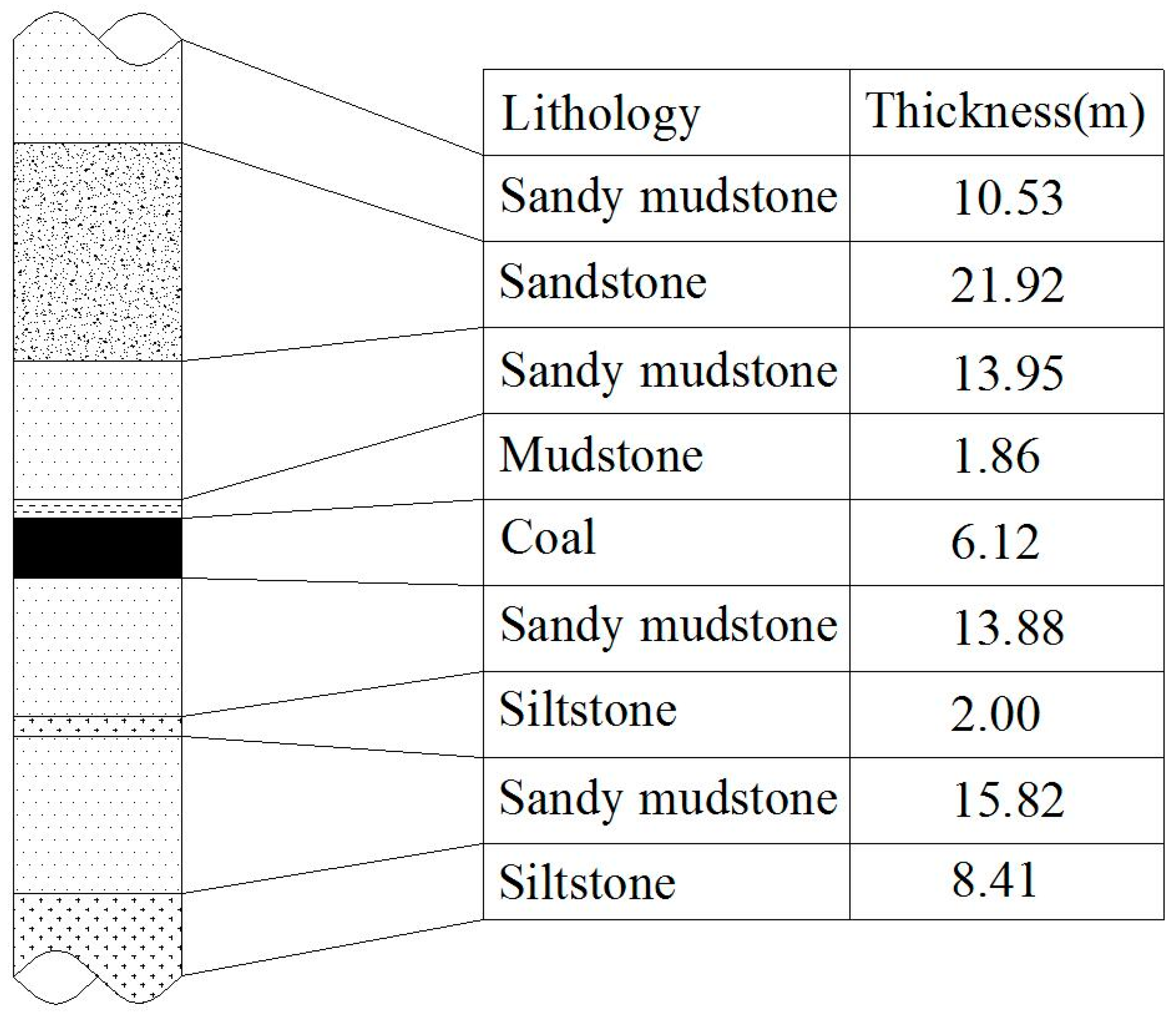
Figure 3, the roof structure was identified by borehole core loggings. A soft and thin layer of mudstone was located immediately above the coal seam as the immediate roof. The main roof mainly consisted of sandstone and sandy mudstone; no hard-to-cave strong stratum was found from the borehole loggings. The floor was mainly sandy mudstone.
Rock core samples were collected on site and laboratory tests were conducted to obtain the mechanical properties of the rocks, and coefficients c1~c4 in Equation (1) were obtained accordingly. Then, based on the estimation method described in
Section 2.1, the height of the CZ and FZ of this panel were estimated to be 12.7 m and 45.5 m, respectively.
The double-yield model, an inherent constitutive model of FLAC3D, is capable of simulating material’s hardening behaviors with increasing strain in compression, and a widely used approach to simulate the mechanical behavior of CZ consolidation [
4,
17,
18,
29]. The input properties of the double-yield model were back-analyzed to match the mechanical behavior of Equation (3) by Jiang et al. [
30].
3.2. Model Description and Simulation Procedure
Considering that the longwall panel is symmetrical around its centerline, a 3D model is generated based on the study site, as shown in
Figure 4. According to the geological column, this model is 190 m wide, 350 m long and 120 m high, and the model size and mesh density were determined based on a sensitivity analysis. The panel was 90 m wide and 250 m long, which left sufficient space to eliminate the boundary effect. It should be noted that, all parameters applied in the numerical simulation came from a previous case study presented in [
28] and [
30], the parameters for boundary conditions were based on in situ stress measurement, and the properties of the rock masses were based on the laboratory tests. To simulate the in situ stress state, a 15 MPa load was vertically applied to the top boundary; according to the in situ stress measurement and previous study [
28], a 12 MPa horizontal load was applied perpendicular to the direction of retreat mining, and an 18 MPa horizontal load was applied along the direction of retreat mining. No displacement in the direction perpendicular to the model lateral boundaries was allowed. In situ stresses were applied as described in
Section 3.1. The rock mass properties for the simulation were estimated from the intact rock properties, as listed in
Table 1. A flowchart of the proposed numerical modeling approach for longwall mining is illustrated in
Figure 5. The simulation process was as follows: (i) Generate the 3D model and assign the constitutive model and properties; (ii) simulate the in situ stress state; (iii) mine the coal seam in the retreat by 10 m for each cycle; (iv) fill the CZ with the double-yield model; (v) run the calculation with the tension-weakening model in the FZ to simulate the rock mass weakening induced by fracturing; (vi) after the calculation reaches equilibrium, repeat (iii) and (iv) until the entire panel is completely mined.
3.3. Parametric Study on the Fracture Intensity of the Fractured Zone
To investigate the tensile failure development in the FZ after the longwall mining had been started, the zones with tensile failure states were identified and are marked in
Figure 6. Many tensile failure zones occurred in the FZ, which was consistent with the description in
Section 2.3. Such extensive rock mass failure in tension requires the consideration of the weakening effect on the rock mass behavior due to failure and fracturing in tension.
Therefore, to investigate the stress distribution and strata behavior with respect to various tensile fracturing intensities, a parametric study of the tension weakening model was performed with four different
GSIt values (as shown in
Table 2), where
Er was the residual Young’s modulus of rock mass after tensile failure,
Em was the Young’s modulus of rock mass before failure, and a high
GSIt indicated high fracture intensity and consequently a low residual Young’s modulus of rock mass according to Equation (6).
4. Fracturing Weakening Effect on the Mining-Induced Stress Redistribution and Strata Movement
The mining-induced stress redistribution and strata movement were three-dimensional. It is well accepted that analysis on these behaviors could be done in two-dimension analytical analysis, by using separate beam models along the strike direction and dip direction of the longwall panel.
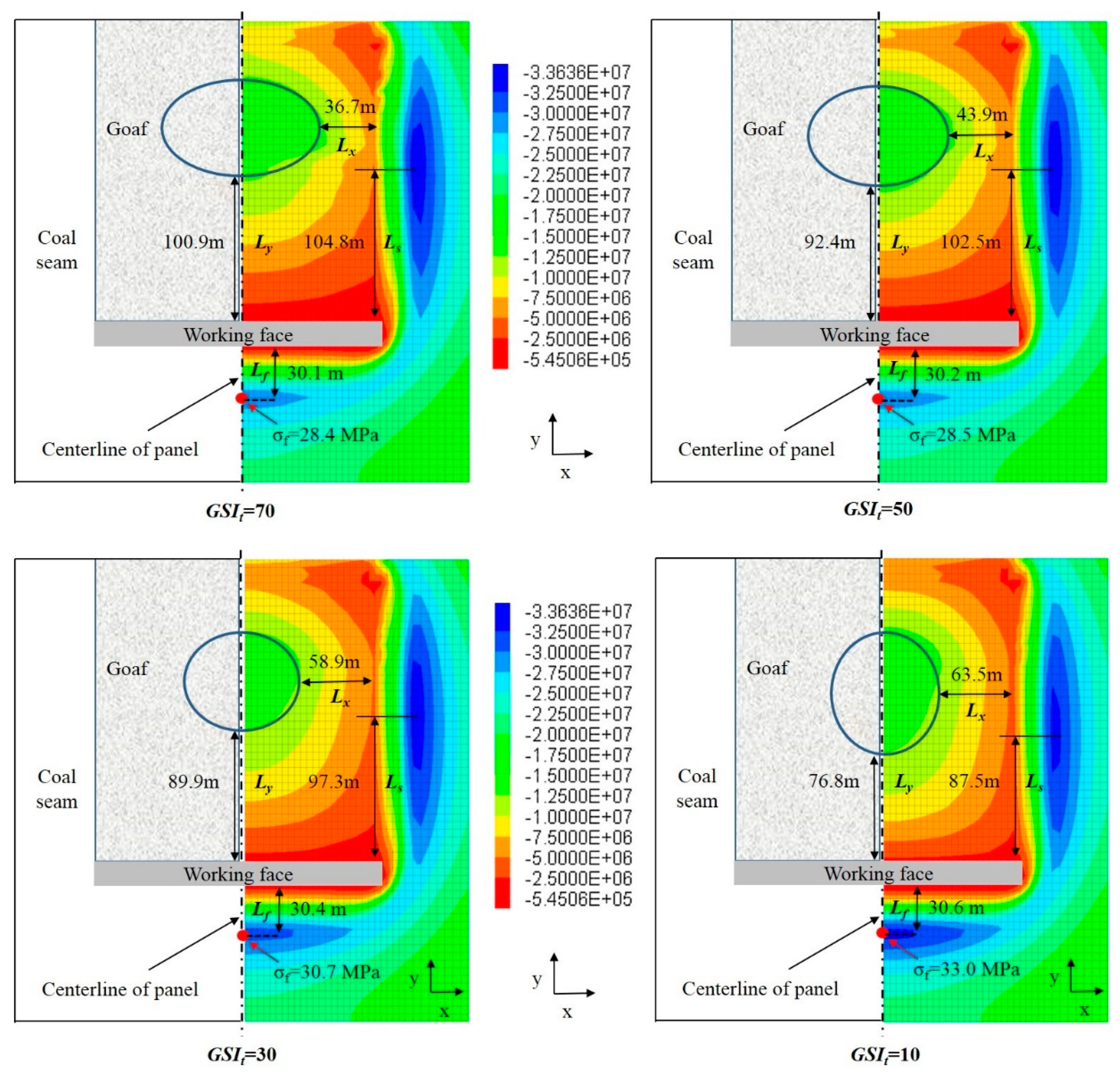
Considering that the panel was symmetrical about its centerline,
Figure 7 shows the mining-induced stress redistribution after the panel had been mined in the retreat by 200 m along its strike with respect to different
GSIt. The tensile fracturing intensity of the FZ significantly affected the stress redistribution due to mining. Ellipses were marked to outline the areas of the goaf where the recovered stress exceeded 12.5 MPa (76.9% of the overburden pressure). In
Figure 7, we also marked the perpendicular distances from the peak front abutment stress (
σf) to the working face (
Lf), from the peak side abutment stress to the face (
Ls), from the face to the edge of the stress-recovered area (
Ly) and from the edge of the stress-recovered area to the lateral goaf edge (
Lx).
As observed from
Figure 7, when the fracture intensity increased (
GSIt decreases), the mining stress field responsed in two aspects: (1) Increase in the front abutment stress; (2) change in patterns of stress recovery in the goaf. The simulation results of the three aspects and their behaviors are analyzed in the following text.
The induced stress concentration ahead of the face, which is known as the front abutment stress, is a paramount parameter for many design practices in longwall mining. As shown in
Figure 7, in the case of
GSIt = 10, which indicates that the FZ had the highest fracture intensity, the peak abutment stress (33.0 MPa) due to mining occurred at 30.6 m ahead of the working face. With the increase in
GSIt, which indicated less tensile fracture in the rock mass, the abutment stress decreased to 28.4 MPa, but the distance to the peak abutment stress hardly moved toward the face. In addition, the area of highly concentrated stress ahead of the face dramatically increased with the decrease in
GSIt. Because the rock mass in the FZ was more fractured (decrease in
GSIt), the massive mining-induced stress tended to redistribute to surrounding rock mass, which resulted in more stress concentrated ahead of the face.
The stress data along the panel centerline in the goaf is shown in
Figure 8 for the quantitative analysis. The stress in the goaf gradually increased because of the compression of the overlying strata and approached the cover pressure far behind the face. Within the first 80 m behind the face, the recovered stress presented a negative correlation with
GSIt, i.e., the cases with a high fracturing intensity in the roof would have more stress concentrated at a certain location in the goaf. However, this trend reversed at a certain point that was far behind the face. The aforementioned simulation results were consistent with one another and can be well explained with the strata structural behavior induced by mining. Numerous studies [
31,
32,
33] have demonstrated that the overlying strata behave like beams along the strike direction of the panel, as illustrated in
Figure 1; applying overburden stress to the goaf and unmined seam will break and cave with an increase in the suspending length because of face advancing, which is called the first and periodic roof weighting phenomenon [
1,
34]. With the increase in fracture intensity, the roof strata are more prone to break and cave, the suspending length of the roof beam will reduce, which makes the strata sufficient enough to break, cave and transfer the overburden load to loose rocks in the goaf (cases of
GSIt = 10 and 30 in
Figure 5 and
Figure 6). When there are few tensile fractures in the strata, the roof beam structure has more stability. A hard-to-break beam with large suspending length over the goaf can only apply an overburden load to the CZ at its pivot far behind the face. This mechanism is well presented in the stress data of
GSIt = 50 and 70 in
Figure 6.
An interesting phenomenon was noticed from the differences in shape of the high-stress-concentration areas in the goaf (marked with ellipses). Taking the axial length along the x-direction as a and the axial length along the y-direction as b, the stress ellipse had a shape of a:b ≈ 1.65 when GSIt = 70 and was located at 100.9 m behind the face and 36.7 m to the lateral goaf-edge; the high-stress area in the goaf extended more along the x-direction than along the y-direction, which indicated that the roof beams along the dip direction of the panel (x-direction) more sufficiently caved than those along the strike direction. When GSIt decreased, the shape and relative location of the ellipse monotonically changed and eventually became an ellipse at 76.8 m behind the face and 63.5 m to the lateral goaf-edge with a:b ≈ 0.88 when GSIt = 10. These results indicated that when the fracturing intensity increased, the roof beams were prone to breaking and caving, which made the high-stress area in the goaf closer to the face (Ly reduces from 100.9 m to 76.8 m), and the caving along the strike direction of the panel became the dominant overlying strata movement. When GSIt was less than 50, the dominant movement caved along the dip direction. This analysis result could also be obtained from the decrease in perpendicular distance from the peak side abutment stress to the face (from 104.8 m to 87.6 m) when GSIt decreased.
5. Discussion and Validation
Using a numerical approach, which can consider the fracture-induced weakening, we investigated the fracture-weakening effect on the mining-induced stress redistribution through a parametric study with respect to the indicator of fracture intensity in tension,
GSIt. According to the analysis in
Section 4, the tensile fracture intensity in the FZ strongly affected the mining-induced stress distribution and strata movement. Thus, this factor should not be ignored in studies related to the behaviors of the FZ, mining-induced stress redistribution and overlying strata movement.
The numerical results of the parametric study showed an interesting and rational changing law, which was consistent with the behaviors of the overlying strata. The changes in fracture intensity led to different abutment stress distributions and roof caving, which contributed to the design of the shield support in the working face.
The in situ stress measurement in longwall mining is generally difficult; there is only a small amount of measured data in this regard [
35,
36,
37]. The extreme difficulties in stress measurement in the non-backfill goaf area [
1] is due to the inaccessibility of the goaf. Even though the stress monitoring cells can be put in the goaf, but are easily damaged by the fallen rocks. Therefore, few attempts have successfully acquired the field stress data in the goaf and have used it to validate the numerical results.
Consequently, the studies on the mining-induced stress and its indicated overlying strata movement often rely on empirical or analytical methods, but only few analytical models are suitable for jointed strata. Singh and Dubey [
38] proposed an expression to estimate the caving span of the jointed roof beam structure
L as follows:
where
F is the orientation factor,
t is the thickness of the bed,
Tr is the rock tensile strength, and
K and
R are the jointing factor and stratification factor, respectively, which are determined by the core study. It was noted that
K and
R had a positive correlation with
L. According to Singh and Dubey’s study, a roof with more fractures would have a lower
K and
R. Therefore, highly jointed and fractured roof strata would have a small caving span, which is consistent with the numerical results presented in
Section 4. Unfortunately, the study of Singh and Dubey [
38] did not describe how to quantify these parameters. Hence, at this stage, Equation (6) could not be directly used to quantitatively validate this numerical study. However, this equation and its indicated relationship is consistent with the trend obtained from the numerical analysis (presented in
Section 4) and hereby served to validate the present study.
According to the aforementioned analysis, the further studies on the quantitative analysis, by means of analytical or numerical analysis, in this regard is surely need to investigate the behaviors of mining-induced roof strata. In addition, the following instructions for applying the Tension weakening model can be drawn: The fracture intensity of the FZ should be case-dependent in light of geological and geotechnical conditions; differences in geological (strata lithology, thickness, properties, etc.) and geotechnical (mining height, length of each mining cycle) conditions will lead to different extents and intensities of the FZ. Hence, it should be estimated based on the core loggings with long roof boreholes or back-analyzed according to field measurements.
This study focused on investigating the mining-induced roof behaviors with a newly proposed simulation technique, and the study was carried out based on a case study with typical geological conditions of underground coal mines. The results of this study may vary with the geological structures and mechanical properties of strata, the sensitivity analysis of different structures and hence these properties will be investigated in future studies.
6. Conclusions
The mining-induced surrounding strata behaviors are characterized into caved zone consolidation and fractured zone development, and their extents and mechanical behaviors have been analyzed and quantified. Accordingly, a numerical modeling approach was proposed by considering the caved zone consolidation and tension-induced fracture-weakening in the fractured zone.
Based on the geological and geotechnical conditions of a study site, a 3D numerical model was built with FLAC3D, and the mechanical properties of the caved zone material were obtained from the back analysis. Extensive rock mass tensile failure occurred in the fractured zone after the retreat-longwall mining began.
To investigate the fracturing weakening effect on the mining-induced stress redistribution and strata movement, a parametric study with respect to various tensile fracturing intensity parameters was conducted. The numerical results showed that the tensile fracture intensity had a notable effect on the mining-induced stress distribution in two aspects: (1) Increase in peak and area of the front abutment stress; when the rock mass in the FZ became more fractured, the massive mining-induced stress tended to redistribute to the surrounding rock mass, which resulted in higher stress concentrated ahead of the face; (2) variation in the patterns of stress recovery in the goaf. The stress data obtained from the numerical simulation represent and help to back-analyze the behaviors (failure, movement) of the overlying strata. The high stress on the coal seam indicated that the strata lay on and transferred loads to the seam, whereas a low stress indicated the detachment between the seam and the suspending strata. With the increase in fracture intensity, the roof strata were more prone to break and cave, and the suspending length of roof beam would decrease, which made the strata sufficiently break, cave and transfer the overburden load to loose rocks in the goaf; the caving along the strike direction of the panel became the dominant overlying strata movement. In the case of strong and intact overlying strata with few tensile fractures, the dominant movement caved along the dip direction.
Considering the fracturing intensity in tension and its induced weakening effect on the rock mass, this study provides a novel simulation approach for studies on the behaviors of the fractured zone, mining-induced stress redistribution and overlying strata movement. According to the simulation results, the tensile fracture intensity in the FZ has a notable effect on the mining-induced stress distribution and strata structural movement. Thus, this factor should not be ignored in studies related to the behaviors of the FZ, mining-induced stress redistribution and overlying strata movement. Based on a proper estimation or back analysis on the roof fracturing state, this presented study and modeling approach can contribute to multiple research areas (such as the shield support design, panel layout and roof water-permeability estimation) when extensive tensile failure is expected in the fractured zone, such as the design of shield support in the working face and panel layout.


