Article

Slag as an Inventory Material for Heat Storage in a Concentrated Solar Tower Power Plant: Design Studies and Systematic Comparative Assessment

DLR (German Aerospace Centre), Institute of Technical Thermodynamics, Pfaffenwaldring 38-40, 70569 Stuttgart, Germany
*
Author to whom correspondence should be addressed.
Appl. Sci. 2019, 9(9), 1833; https://doi.org/10.3390/app9091833
Submission received: 25 February 2019 / Revised: 12 April 2019 / Accepted: 25 April 2019 / Published: 3 May 2019
(This article belongs to the Special Issue Clean Energy and Fuel (Hydrogen) Storage)

Abstract

:

Featured Application

Concentrated solar power (CSP) plant with open volumetric receiver.

Abstract

By using metallurgical slag from an electric arc furnace that is otherwise not recycled but deposited as an inventory material in thermal energy storage for concentrated solar power plants, it is possible to make a significant step forward in two transformation processes: energy and raw materials. As this type of slag has not been considered as an inventory material for this purpose, it is important to clarify fundamental questions about this low-cost material and its storage design. In this paper, design studies of slag-based thermal energy storage are carried out. Different slag-specific design concepts are developed, calculated and evaluated by a method based on established management tools. Finally, concepts for further investigations are defined. The highest aptitude value and the lowest risk value are achieved by the vertical storage design with axial flow direction. Therefore, it is taken as the lead concept and will be considered in complete detail in further research. Also, a closer look, but not as detailed as the lead concept, is taken at the horizontal storage with axial flow and the vertical storage with radial flow direction.

1. Introduction

Concentrated solar power (CSP) plants, in conjunction with photovoltaic systems, can contribute to a safe, clean and cost-effective electric power supply in the Earth's equatorial sun-belt [1]. The use of heat storage allows CSP plants to generate dispatchable electricity, and thus make an important contribution to the global energy transition [2].
To protect the environment and conserve primary raw materials, a raw material transition is also required [3,4,5]. This succeeds only with the efficient use of primary raw materials and the most complete possible use of secondary raw materials. This is addressed by German and European politicians through the German Resource Efficiency Programme II [6] and the EU Initiative for a Resource Efficient Europe [7].
By using metallurgical slag from an electric arc furnace (EAF), that is otherwise not recycled but deposited as an inventory material in thermal energy storage (TES) for CSP plants, it is possible to make a significant step forward in two transformation processes: energy and raw materials.

2. State of the Art of TES in CSP Plants

In CSP plants, molten salt technologies have been extensively deployed in CSP applications for the storage of thermal energy prior to steam or electricity generation. An example among many is the Solana power plant with 280 MWe and a storage system able to supply full power for six hours. [2]
The technology of regenerator-type storage is less developed, but has the potential for higher efficiency and lower costs. In particular, the application of regenerators in CSP power plants with an open volumetric receiver seems to be a promising approach, as shown in Figure 1.
The Jülich solar power tower in Germany, seen in Figure 2, is currently the only plant in the world to be based on this technology. This experimental central receiver plant was inaugurated in 2009 to facilitate the further development of this technology. The erection and operation of the plant have been accompanied by a research program, whose objective is to cover the remaining uncertainties around design and operation and to further promote the development of the technology towards a commercial deployment. As a part of this work program, heat storage operation and design are also addressed [8].
As mentioned before, the plant uses an open volumetric receiver technology developed at DLR (German Aerospace Centre). In its primary cycle, air at atmospheric pressure is heated up to temperatures of about 700 °C. This solar heat then powers a steam generator, producing steam at 100 bars and 500 °C and driving a 1.5 MWel turbine-generator set. In parallel to the steam generator and receiver, thermal energy storage is integrated into the power cycle, as seen in Figure 1. It is implemented as an air-cooled regenerator storage system, an installation that is still unique in this application. The state of the art is set with the recently completed HOTSPOT project [9].
Generally, with regenerator-type storage, temperatures of up to 1000 °C and even more can be realized by using solid storage material such as commercially available bricks or beds of smaller particles made of oxide ceramic material [10]. Recent work [11,12,13,14] is investigating low-cost alternative inventory materials such as low-temperature-fired clay bricks and magmatic natural stones.
An alternative to this is slag from an electric arc furnace (EAF). Since this type of slag has not been considered as an inventory material for this purpose, it is important to clarify fundamental questions about the material and TES design. These questions are addressed by the REslag project. The main objective of the project is to make an effective valorization of the steel slag and reuse it as a feedstock for four innovative applications, one of which is thermal energy storage systems in CSP applications [15,16].
The degradation effects of the fluid by direct contact with the slag, which are reported, for example, by Grosu et al. [17] in another type of slag, are, in contrast to molten salt, not of importance in the air or can be equalized by correspondingly high air exchange rates. The issue of safety in the context of molten salt is also to be assessed much more critically than with air. The safety regulations for slag are also manageable with this system, as it is a closed circuit and the slag used is classified by the manufacturer as a non-hazardous substance.
In this paper, design studies of slag-based thermal energy storage are carried out. Different design concepts are developed, calculated and evaluated. Finally, the lead concepts for further investigation in the project are defined.

3. Design of Slag-Based TES

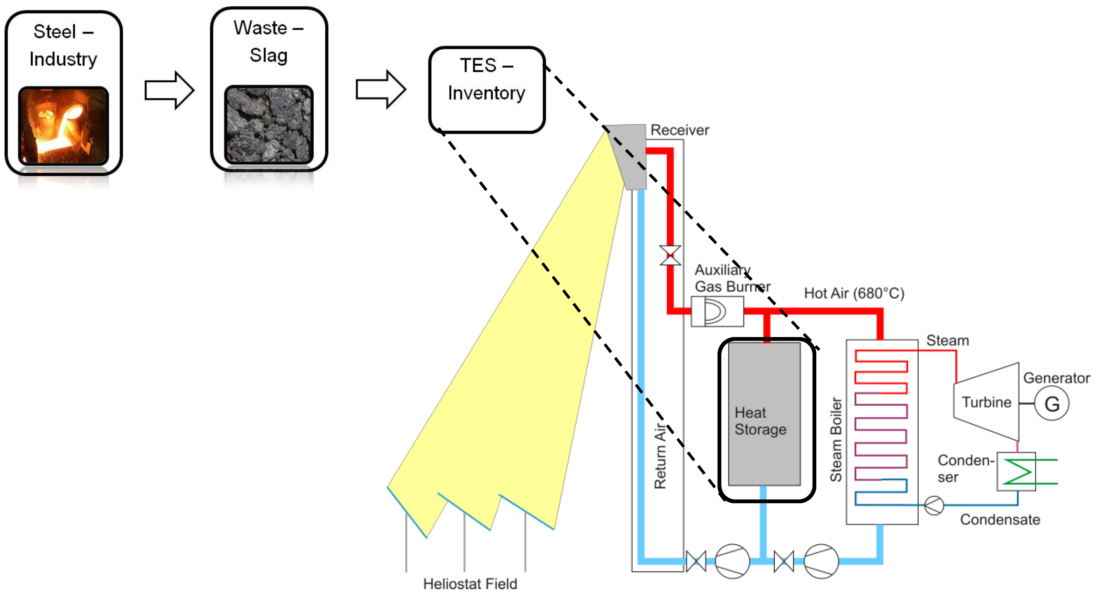
3.1. CSP Plant Target Specifications

Since the Jülich solar power tower (see Figure 2) is the only facility of its kind, and is only a demonstration plant, no targets for large systems can be defined. Under these circumstances, literature research was independently performed. However, as no consistent record of a specialized plant exists, the collected data can only serve as guide values. Accordingly, the target figures were determined on the basis of existing knowledge, as shown in Table 1.

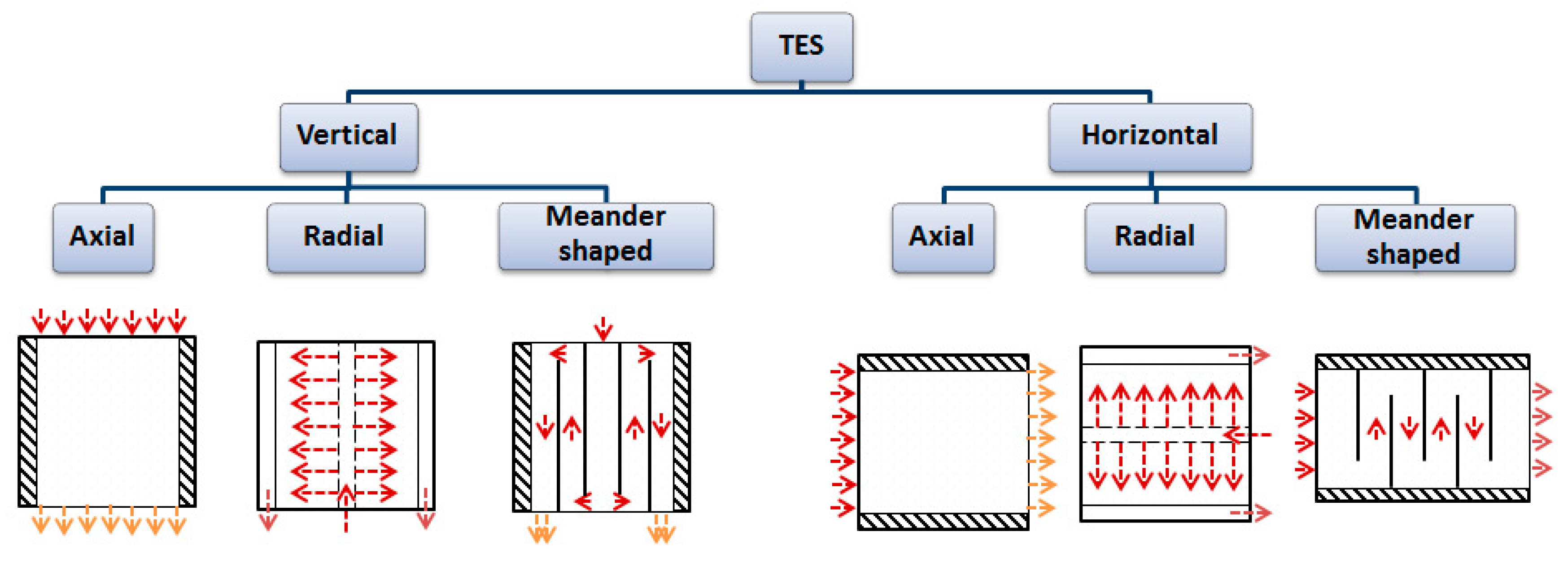
3.2. Considered TES Designs

Various possible basic TES designs are tested for suitability and compared to determine the most suitable option for slag-based TES. Figure 3 shows an overview of the options considered. They differ in their positioning and flow direction, namely, axial, radial and meandering.
The comparison of the vertical and the horizontal variants reveals that the axial and radial concepts are rotated only by 90 degrees, while the meander-shaped variant is fundamentally different. In the vertical variant, it goes radially from the inside to the outside, thus also increasing the flow cross-sectional area. In the horizontal variant, the size of the cross-sectional area always remains the same; there is only a change in the direction of flow from one chamber to the next.
While the meander-shaped variant is a fundamental innovation, the axial variant has previously been considered and represents the state of the art in vertical position. The radial flow is also very innovative but has been studied in [11,12]. The special feature here is the constantly changing cross-sectional area along the flow path. In order to get a better understanding of each concept and the reason why it is considered, the main advantages and disadvantages are listed in Table 2.

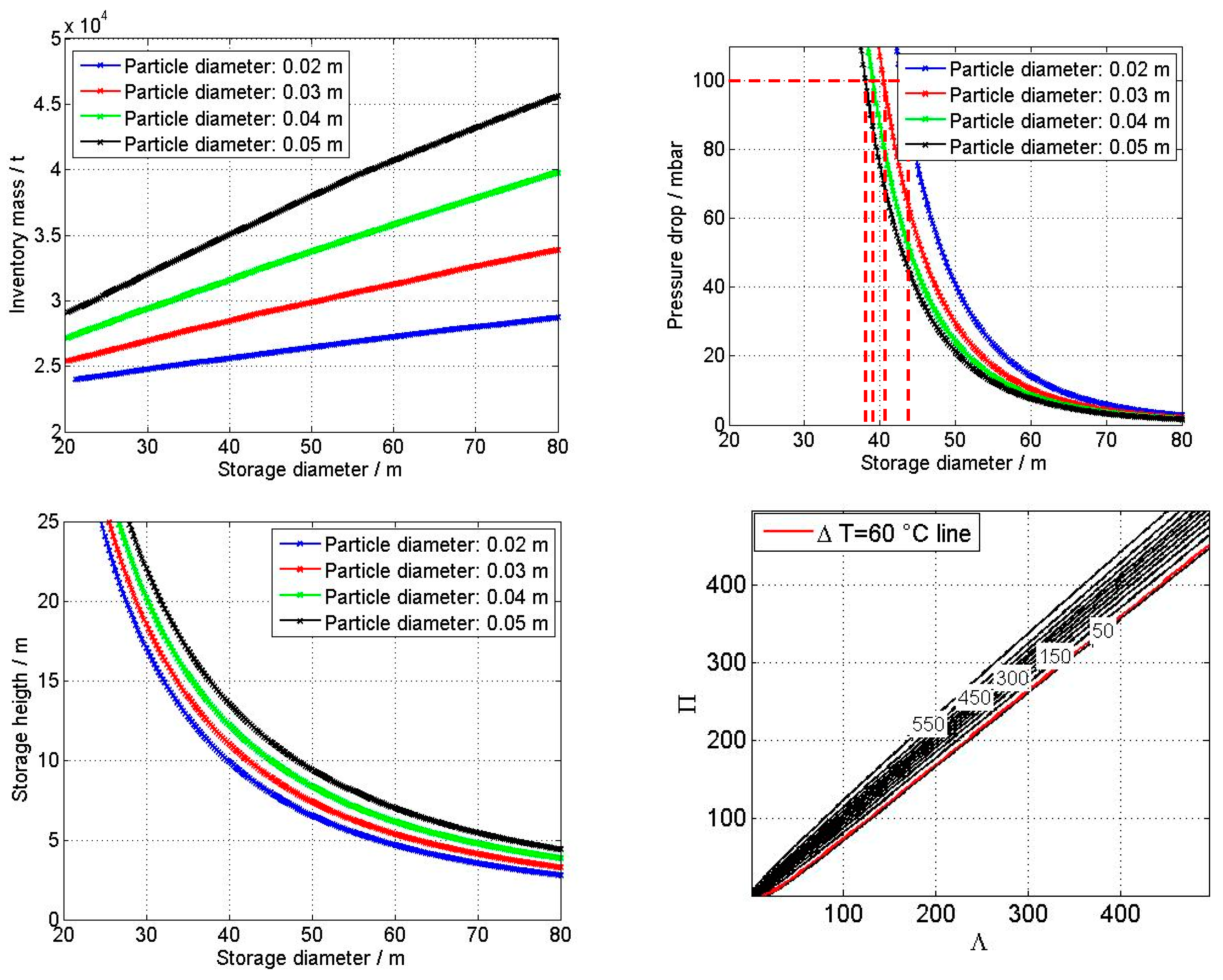
3.3. Pre-Design of Storage

By using simplified models based on the Λ-Π-method [18] at a specific site taking into consideration the course of the sun, the geometrical properties for each thermal energy storage design from Figure 3 under different parameter variations are calculated. Here, just the results for the vertical TES are presented as an example.

Dimensioning of TES

The given CSP plant specifications (Table 1) and the slag properties listed in Table 3 are included in the calculation of the heat storage dimensions. The results are shown as fields in Figure 4.
Depending on the slag particle diameter used, the maximum pressure loss is 100 mbar with a storage diameter of approx. 38 to 44 m and a storage height of 8 to 12 m. The large diameters are structurally more challenging, so the heat storage is divided into three smaller modules connected in parallel.

3.4. Comparative Assessment and Definition of a Lead Concept

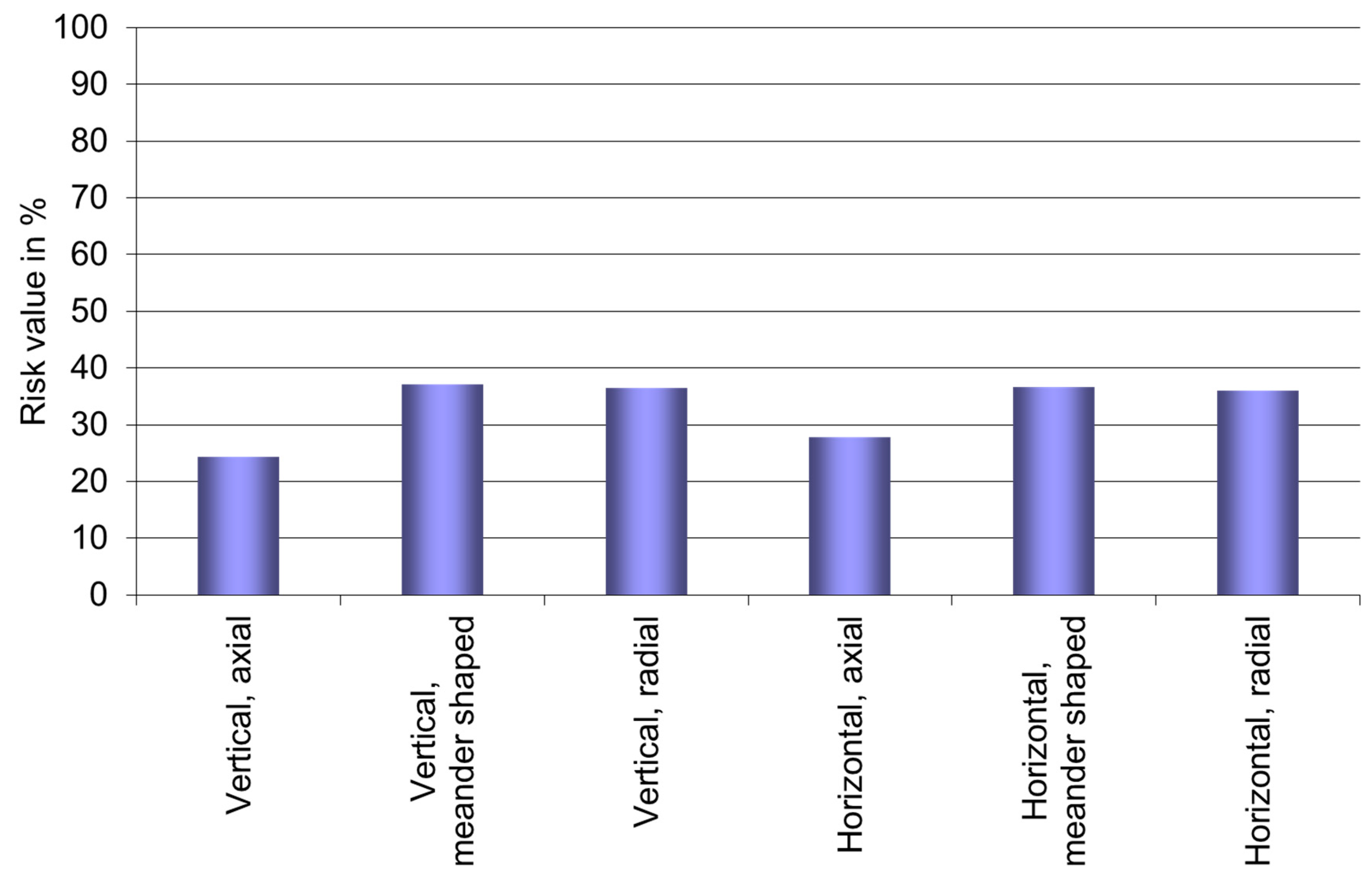
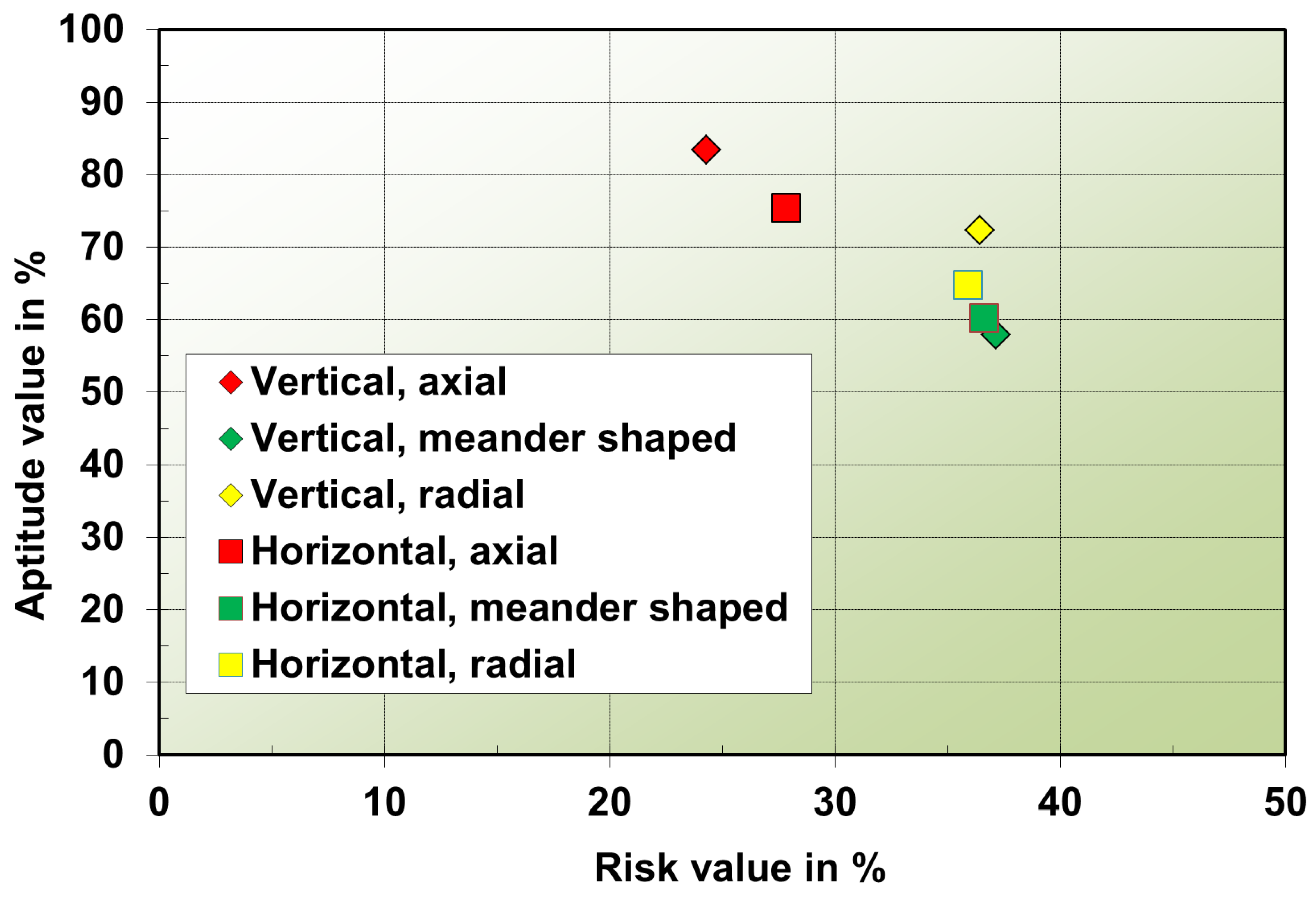
Quality Function Deployment (QFD) and Failure Mode and Effect Analysis (FMEA)

For the identification of the lead concept, an evaluation method was developed, which is essentially based on QFD and FMEA, and includes an aptitude analysis and a risk analysis. Both methods, QFD and FMEA, are established management tools used in product development. While the aim of QFD is to successfully fulfil the wishes of the customers in their products and services, the use of FMEA attempts to minimize potential errors and risks. Extensive information on QFD and FMEA can be found elsewhere [20,21]. The two methods have been simplified for the present usage for deciding which design of slag-based TES is the best and has the lowest risks. The analysis approach used is described by Figure 5.
Firstly, criteria of the aptitude analysis were collected and divided into two different groups, economical and technical demands, with the first group weighted by 0.6 and the second by 0.4. This is due to the fact that the main focus is on cost reduction by using a very inexpensive inventory material—provided that the functionality is performed. All points considered in the aptitude analysis are listed in Table 4. Secondly, these criteria were prioritized among each other by pair-by-pair comparisons and the listed weighting factor of each criterion was generated accordingly.
Each concept was then evaluated according to the criteria developed previously. For this purpose, a so-called aptitude factor was introduced. The design results presented in the previous section are also taken into account here. The multiplication of these two factors and the subsequent addition of the individual criterion values results in an aptitude value for each concept. The results are shown in Figure 6.
The highest value is achieved by the vertical TES with axial flow direction (83%), followed by the horizontal TES with axial flow direction (75%) and the vertical TES with radial flow direction (72%). Mainly, this is caused by high aptitude values in the areas that have high weighting factors. In particular, operational availability, lifetime, investment costs and degree of maturity should be mentioned here. While horizontal setups promise longer lifetimes due to less inventory material failure, the more or less state-of-the-art vertical axial design achieves better scores with the degree of maturity, operational availability and investment costs criteria. Radially flowed variants have significant advantages in terms of operating costs due to low pressure losses along the flow path and the storage degree of uniformity. In the overall assessment, however, the vertical axial concept is slightly ahead of the horizontal axial and vertical radial concept.
As a second step, the risk analysis was implemented. As with the aptitude analysis mentioned above, this was done in several steps. First, possible risks were identified (see Table 5) and estimated in relation to the potential damage when the damaging event occurred. This leads to a so-called damage factor (see Table 5). Secondly, each concept was also evaluated according to the probability of occurrence of the damaging events. A probability factor was therefore generated. The third step was carried out as in the aptitude analysis: the factors were multiplied and each risk value was summed. This results in a risk value for each concept, as shown in Figure 7.
The lowest value is achieved by the vertical TES with axial flow direction (24%) followed by the horizontal TES with axial flow direction (28%). As there are no different probabilities of occurrence for the risks with a high damage factor (operational safety and corrosion), the results are mainly influenced by criteria with medium damage factors. In particular, thermal and fluid mechanical design uncertainties as well as material failure should be mentioned here. While horizontal setups promise less inventory material failure, the more or less state-of-the-art vertical axial design achieves lower probability factors with the design uncertainties criteria. Radially flowed and meander-shaped variants have significant disadvantages in terms of design uncertainties. Although the thermal design uncertainties are small in themselves, the fluid mechanical design uncertainties have to be assigned a higher probability of occurrence due to possible bypass flows in the case of horizontal axial flow TES. In the overall assessment, however, the vertical axial concept is slightly ahead of the horizontal axial concept.
At the end of the QFD analysis, both aptitude values and risk values were plotted in a diagram, as shown in Figure 8. It is important to note that a high value of risk is not necessarily problematic for a research project because research can reduce risks.
Three of the six concepts have aptitude values above 70%. The highest value is achieved by the vertical TES with axial flow direction, which also indicates the lowest value of risk. In summary, this is an expression of the techno-economic optimum and the highest degree of maturity. It is therefore defined as the lead concept and will be fully taken into account in the further course of the project. Also, a closer look, but not as detailed as the lead concept, is taken at the horizontal TES with axial flow and the vertical TES with radial flow direction. This is done due to the fact that these two concepts also achieved a high aptitude value and thus have high potential.
In order to demonstrate the competitiveness of slag-based TES and to further reduce technical uncertainties, detailed research on materials and design as well as pilot plant trials are being conducted as part of the REslag project.

4. Summary and Conclusions

The use of metallurgical slags from EAF as inventory material for TES for CSP plants has not yet been intensively investigated and offers the opportunity to save raw materials and energy at the same time. Economically, the material offers the advantage of being a very cost-effective alternative to conventional inventory materials for solid heat storage. Since, however, the thermophysical properties of the slags under consideration are very similar to those of conventional refractory materials and ceramics, the TES concepts which are structurally simple and functional and pose the lowest technical risks will prevail.
In this paper, different slag-specific design concepts are systematically evaluated. For this purpose, an evaluation procedure based on QFD and FMEA was developed, which makes it possible to objectively evaluate the suitability and the risk of different concepts and thus to define the most suitable concepts. In the concepts examined here, which differ in their different installation methods and flow directions, the vertical TES with axial flow direction performed best, as it has both the best aptitude value and the lowest risk value. It forms the techno-economic optimum. The partly better functionalities of the other concepts are not so decisive here. It is therefore defined as a lead concept and will be further developed in the course of the REslag project. The horizontal TES with axial flow and the vertical TES with radial flow direction will also be investigated in less detail.

Author Contributions

The paper was written by M.K. under the guidance of S.Z. The pre-design of storage was carried out by J.H. The comparative assessment and definition of a lead concept were carried out by M.K., J.H. and P.K.

Funding

This project has received funding from the European Union’s Horizon 2020 research and innovation programme under grant agreement No. 642067.

Conflicts of Interest

The authors declare no conflict of interest. The funders had no role in the design of the study; in the collection, analyses, or interpretation of data; in the writing of the manuscript, or in the decision to publish the results.

References

  1. Pitz-Paal, R. Solar Energy-Concentrating Solar Power. In Future Energy; Elsevier Science: New York, NY, USA, 2014; pp. 405–431. [Google Scholar]
  2. European Association for Storage of Energy (EASE); European Energy Research Alliance (EERA). European Energy Storage Technology Development Roadmap-2017 Update; EASE/EERA: Brussels, Belgium, 2017. [Google Scholar]
  3. Temporärer ProcessNet-Arbeitskreis Rohstoffe und Kreislaufwirtschaft. Anorganische Rohstoffe - Sicherung der Rohstoffbasis von Morgen; DECHEMA, e.V.: Frankfurt, Germany, 2015. [Google Scholar]
  4. Buchert, M. Press Release: Transition to Sustainable Raw Materials Management Needed in Germany; Oeko-Institut: Freiburg/Berlin, Germany, 2015. [Google Scholar]
  5. Öko-Institut, e.V. Rohstoffwende 2049: Zur Zukunft der Nationalen und Internationalen Rohstoffpolitik. Jahrestagung; Öko-Institut e.V.: Freiburg, Germany, 2016. [Google Scholar]
  6. Federal Ministry for the Environment, Nature Conservation and Nuclear Safety. German Resource Efficiency Programme II-Programme for the Sustainable Use and Conservation of Natural Resources; Federal Ministry for the Environment, Nature Conservation and Nuclear Safety: Berlin, Germany, 2016. [Google Scholar]
  7. European Commission. Communication from the Commission to the European Parliament, the Council, the European Economic and Social Committee and the Committee of the Regions: Roadmap to a Resource Efficient Europe; European Commission: Brussels, Belgium, 2011. [Google Scholar]
  8. Zunft, S.; Hänel, M.; Krüger, M.; Dreißigacker, V.; Göhring, F.; Wahl, E. Jülich Solar Power Tower-Experimental Evaluation of the Storage Subsystem and Performance Calculation. J. Sol. Energy Eng. 2011, 133, 1019–1023. [Google Scholar] [CrossRef]
  9. Zunft, S.; Hänel, M.; Krüger, M.; Dreißigacker, V. A design study for regenerator-type heat storage in solar tower plants-Results and conclusions of the HOTSPOT project. Energy Procedia 2014, 49, 1088–1096. [Google Scholar] [CrossRef]
  10. Laing, D.; Zunft, S. Using concrete and other solid storage media in thermal energy storage (TES) systems. In Advances in Thermal Energy Storage Systems: Methods and Applications; Woodhead Publishing: Cambridge, UK, 2015; pp. 65–86. [Google Scholar]
  11. Stahl, K.; Moser, P.; Marquardt, R.; Siebert, M.; Kesser, S.; Maier, F.; Krüger, M.; Zunft, S.; Dreißigacker, V.; Hahn, J. Flexibilisierung von Gas- und Dampfturbinenkraftwerken durch den Einsatz von Hochtemperatur-Wärmespeichern (FleGs): F&E Vorhaben zur Vorbereitung von Hochtemperatur-Wärmespeichern und Deren Integration in den Gas- und Dampfturbinenprozess; RWE Power AG: Essen, Germany, 2013. [Google Scholar]
  12. Stahl, K.; Zunft, S.; Kessler, S.; Siebert, M. Flexibilisierung von GuD-Kraftwerken durch den Einsatz von Hochtemperatur-Wärmespeichern. In VDI-Konferenz “GuD-Kraftwerke im Dynamischen Netzbetrieb”, 29–30 November, Köln Germany; Verein Deutscher Ingenieure (VDI): Düsseldorf, Germany, 2011. [Google Scholar]
  13. Zunft, S.; Freund, S. Large-scale Electricity Storage with Adiabatic CAES-the ADELE-ING project. In Proceedings of the Energy Storage Global Conference, Paris, France, 19–21 November; Energy Storage Association: New York, NY, USA, 2014. [Google Scholar]
  14. Zunft, S. ADELE-ING: Engineering-Vorhaben für die Errichtung der Ersten Demonstrationsanlage zur adiabaten Druckluftspeichertechnik; German Aerospace Center: Stuttgart, Germany, 2017. [Google Scholar]
  15. Krüger, M.; Haunstetter, J.; Zunft, S. Concentrated solar tower power plant using slag as inventory material for a thermal energy storage (TES). In AIP Conference Proceedings; AIP Publishing: Melville, NY, USA, 2018; Volume 2033, pp. 090018-1–090018-8. [Google Scholar]
  16. RESLAG. Available online: http://www.reslag.eu (accessed on 18 February 2019).
  17. Grosu, Y.; Ortega-Fernández, I.; del Amo, J.M.L.; Faik, A. Natural and by-product materials for thermocline-based thermal energy storage system at CSP plant: Compatibility with mineral oil and molten nitrate salt. Appl. Therm. Eng. 2018, 136, 657–665. [Google Scholar] [CrossRef]
  18. Dreißigacker, V.; Müller-Steinhagen, H.; Zunft, S. Thermo-mechanical analysis of packed beds for large-scale storage of high temperature heat. Heat Mass Transf. 2010, 46, 1199–1207. [Google Scholar] [CrossRef]
  19. Ortega-Fernández, I.; Calvet, N.; Gil, A.; Rodríguez-Aseguinolaza, J.; Faik, A.; D’Aguanno, B. Thermophysical characterization of a by-product from the steel industry to be used as a sustainable and low-cost thermal energy storage material. Energy 2015, 89, 601–609. [Google Scholar] [CrossRef]
  20. Akao, Y. Quality Function Deployment: Integrating Customer Requirements into Product Design; Productivity Press: Cambridge, UK, 1990. [Google Scholar]
  21. Akao, Y.; Mizuno, S. QFD: The Customer-Driven Approach to Quality Planning and Deployment; Asian Productivity Organisation: Tokyo, Japan, 1994. [Google Scholar]
Figure 1. Flowsheet of slag reuse as a thermal energy storage (TES) inventory for a concentrated solar power (CSP) plant with an open volumetric receiver.
Applsci 09 01833 g001
Figure 2. Jülich solar power tower (Germany).
Applsci 09 01833 g002
Figure 3. Matrix of variants for TES.
Applsci 09 01833 g003
Figure 4. Simulation results of designing the TES.
Applsci 09 01833 g004
Figure 5. Quality function deployment (QFD)- and failure mode and effect analysis (FMEA)-based analysis approach.
Applsci 09 01833 g005
Figure 6. Aptitude values for each concept.
Applsci 09 01833 g006
Figure 7. Risk value for each concept.
Applsci 09 01833 g007
Figure 8. Results of the comparative assessment.
Applsci 09 01833 g008
Table 1. Concentrated solar power (CSP) plant specifications.
DescriptionCharacterizationComments
Rated net power output of CSP plant150 MWel
TES capacity6.5 h
(2.21 GWh)
Considering the solar multiple factor and charging duration.
Temperature at TES inlet while charging700 °C
Temperature at TES inlet while discharging120 °C
Max. temperature drop at TES outlet while discharging60 °C
Max. pressure loss through the TES while discharging100 mbar
Discharging mass flow780 kg/sAt design point (12 p.m., 21 March)
Max. charging mass flow through TES1080 kg/sAt design point (12 p.m., 21 March)
Mean charging mass flow through TES706 kg/sOn design day (21 March)
Charging duration8 hAssumption: sinusoidal course of the sun
Considering the solar multiple factor and sunshine hours
Hours of sunshine on design day (21 March)12.2 hLocation: Huelva (Spain)
Solar multiple2At design point (12 p.m., 21 March)
Table 2. Advantages and disadvantages of considered thermal energy storage (TES) designs.
TES OptionAdvantageDisadvantage
Vertical TES
  • Easy to fill
  • Insulation can be placed easily
  • Space saving
  • Most previous knowledge
  • Bottom piping can be complex
Horizontal TES
  • Reduction in height
  • Distributor is easier to mount
  • Rectangle-shaped instead of cylindrical, easier to support storage walls
  • More complicated to fill
  • Needs more ground space than vertical
Axial flow
  • Basic concept
  • Most previous knowledge
  • Lower degree of uniformity compared with radial flow
Radial flow
  • Reduced distributor space
  • Better degree of uniformity compared with axial flow
  • Overflow losses
Meander-shaped flow
  • Higher storage degree of utilization
  • Reduced storage height
  • Increased filling effort
  • Higher inventory costs (additional installations)
Table 3. Electric arc furnace (EAF) slag characteristics [19].
DescriptionCharacterizationComments
Density3430 kg/m3
Thermal conductivity1.43 W/(m K)at 500 °C
Specific heat capacity0.933 kJ/(kg K)at 500 °C
Table 4. Criteria for aptitude analysis.
GroupCriterionDescriptionWeighting Factor
Economical demandLow investment costsWill be calculated in a simplified way; includes inventory, containment and liner (protects insulation) costs. Simple designs without internals for flow guidance and distribution have advantages here.7.1
Low operating costsWill be calculated in a simplified and qualitative way; includes, e.g., auxiliary power for ventilation, costs for inventory change etc.5.9
High storage degree of utilizationIs calculated by thermal simulation; indicates the utilization of the inventory, that means how much of the inventory undergoes the full temperature increase.0.6
Low space needBase area of container is considered as well as the needed container number.1.8
High operational availabilityIs reduced, for example, by out of order or maintenance times of the TES. Possible bypass flows due to settlement effects and hazards to thermal insulation at hot points due to high loads are taken into account.10.0
Long lifetimeOf the TES and its subcomponents. The higher the inventory level, the higher the forces on inventory, insulation and container. The lower the inventory level, the more gentle on the materials and the higher the potential lifetime.10.0
Technical demandLow expense of protection for insulationThe basis is an inner liner which is used from a storage height of 10 m.4.1
High storage degree of uniformityRatio of effective emitted energy over discharge duration to maximal possible energy withdrawal over discharge duration.9.0
Low complexityOf the construction and connection.7.2
High degree of maturityCommercial availability of components. Concepts already available on the market must be evaluated as better than those for which only test setups or even only drawings exist.10.0
Good scalabilityTo larger or smaller storage8.7
Low expense of system integrationOf the TES.6.7
Low expense of fluid distributionGood and even fluid distribution.3.8
Low expense of insulationInner and outer insulation of the TES.3.6
Low expense of fillingFilling the TES with slag pebbles.2.1
Low maintenance effortLevel of access. In particular, good accessibility at all points is crucial here.6.7
Low cleaning effort of working fluidFilter mandatory? Cleaning amount of filter.4.6
Low safety effortSafety must be ensured but at what expense?1.3
Table 5. Criteria for risk analysis and damage factors.
CriteriaDescriptionDamage Factor *
Thermal design uncertaintiesUncertainties in material parameters, model uncertainties5
Thermomechanical design uncertaintiesUncertainties in material parameters, model uncertainties3
Fluid mechanical design uncertaintiesModel uncertainties5
Material failureInventory, insulation4
CorrosionInventory, insulation, container, piping (everything that is in contact with the high temperature fluid (HTF))7
Operating restrictions due to the complexity of the storage systemPiping, amount of container, storage installations, isolation equipment4
Operational safetyOuter damages which can influence the operational safety, e.g., fluid leaking9
Economic uncertaintiesFalse estimation of investment and operational costs2
Lack of competition for plant componentsLow amount of providers or no provider for essential components3
* High damage factor (7–10): Hazard to human life; effect on whole plant (required changes); large effect on plant performance, lifetime and availability. Medium damage factor (4–6): derated operation possible; effect on related components (required changes); medium effect on plant performance, lifetime and availability. Low damage factor (1–3): effect on TES only (required changes); low effect on plant performance, lifetime and availability.

