Article

Hollow Fiber Membrane Dehumidification Device for Air Conditioning System

Department of Chemical & Biomolecular Engineering, National University of Singapore, Singapore 117585, Singapore
*
Author to whom correspondence should be addressed.
Membranes 2015, 5(4), 722-738; https://doi.org/10.3390/membranes5040722
Submission received: 24 July 2015 / Accepted: 9 November 2015 / Published: 16 November 2015
(This article belongs to the Special Issue Membranes for Environmental Applications)

Abstract

:
In order to provide a comfortable living and working environment indoors in tropical countries, the outdoor air often needs to be cooled and dehumidified before it enters the rooms. Membrane separation is an emerging technology for air dehumidification and it is based on the solution diffusion mechanism. Water molecules are preferentially permeating through the membranes due to its smaller kinetic diameter and higher condensability than the other gases. Compared to other dehumidification technologies such as direct cooling or desiccation, there is no phase transition involved in membrane dehumidification, neither the contact between the fresh air stream and the desiccants. Hence, membrane dehumidification would not only require less energy consumption but also avoid cross-contamination problems. A pilot scale air dehumidification system is built in this study which comprises nine pieces of one-inch PAN/PDMS hollow fiber membrane modules. A 150 h long-term test shows that the membrane modules has good water vapor transport properties by using a low vacuum force of only 0.78 bar absolute pressure at the lumen side. The water vapor concentration of the feed humid air decreases dramatically from a range of 18–22 g/m3 to a range of 13.5–18.3 g/m3. Most importantly, the total energy saving is up to 26.2% compared with the conventional air conditioning process.

Graphical Abstract

1. Introduction

Singapore as one of the tropical countries and it has a uniformly high temperature from 28 °C to 32 °C and a humidity of above 85% throughout the year [1]. However, the recommended indoor air temperature and relative humidity for living and working comfortably is around 23 °C to 26 °C and 45% to 60%, respectively [2]. In order to provide a comfortable living and working environment indoors, specifically in Singapore, the outdoor air should be cooled and dehumidified before it is circulated into the rooms. The current widely used and accepted technologies for removing air moisture are either direct cooling by chillers or desiccations. As for the direct cooling, the chiller in the air handling unit (AHU) usually first cools the humid air to its saturation temperature and then condenses the excessive moisture into water. Since the moisture goes through the phase transition process during the condensation, direct cooling is energy intensive. Removing humidity by desiccants is a simple method [3,4,5,6]. However, the process to regenerate the desiccants is energy intensive and desiccants have the risk of cross-contamination to the air stream.
Membrane technology for air dehumidification is based on the solution diffusion mechanism, where the water molecule preferentially permeates through the membranes due to its smaller kinetic diameter and higher condensability than the other gases. There is no phase transition involved neither the contact between the fresh air stream and the desiccants, hence it requires minimal energy consumption and can avoid the cross-contamination problems. In addition, membrane systems have the advantages of a small footprint, and easy scale-up and adaption compared to other available units in the whole system.
Since the selectivity of polymeric materials for water over air is usually high [7], gas separation membranes can be used for dehumidification directly without modifications. From the first success of the Prism’s hydrogen recovery process, followed by the separation of carbon dioxide from methane, oxygen from nitrogen, membrane gas separation technologies have received significant attention from both academia and industries over the years [8,9,10]. To date, about less than 10 polymeric materials have been used in commercial gas separation membranes out of hundreds of polymers synthesized for gas separation studies in the literature [11,12,13,14]. One of the most important criteria for commercially available gas separation membranes is to have an ultra-thin dense selective layer [15,16] to promote high gas transport properties. Both integrally skinned and multilayer composite approaches have been employed to fabricate gas separation membranes [15,16,17,18,19,20,21,22,23,24,25]. For dehumidification membranes, the microporous support layer may be the dominant resistance to water transport, which is opposed to traditional gas separation membranes where the selective layer is the dominant resistance. Thus, a desired membrane comprising a highly microporous substrate and a thin, dense selective layer is crucial for dehumidification system [26].
Peinemann and his co-workers [23,24] and Li et al. [25] have successfully fabricated various multi-layer composite membranes with superior CO2/N2 and O2/N2 separation performance. Since we are familiar with Li et al. approach and their composite PDMS-coated PAN hollow fibers performed well under low pressures (about 15 psi) compared to other gas separation membranes (usually operated under 100 psi and above), PDMS-coated PAN composite hollow fibers will be fabricated and used in our membrane dehumidification system.
Membrane dehumidification for compressed air or natural gas is a well-studied process and several hollow fiber membrane products are commercially available [27,28,29,30,31,32]. Basically, the moisture permeation rate through a membrane is a function of the partial pressure difference of the moisture across the membrane. Since the gas permeation selectivity of water over air is high, the water vapor partial pressure in the permeate side can quickly reach that of the feed side, as a result, it slows down the dehydration efficiency. One method to overcome it is to utilize a sweep gas [26,33]. Morgan et al. from Air Products patented a hollow fiber dehydration method and apparatus using an internal sweep of the permeate side by a dry gas product [7]. This invention works well under high operation pressures (above 7 bars). Other than that, some researchers have studied the impact of vacuum and sweep gas for the feed gas operated below 7 bar and modeling the energy demand for air dehumidification versus traditional systems [34,35,36,37].
In this work, we aimed to develop a pilot-scale membrane dehumidifier and pave the feasibility of assembling the membrane system with the AHU units where low pressures are used. Our main objectives are (1) to scale up the PAN/PDMS composite hollow fiber modules from a lab scale to a pilot scale; (2) to design a pilot membrane dehumidification system working under low pressures and test its long-term performance stability; and (3) to calculate the energy savings using our home-made membrane dehumidifier together with the AHU.

2. Experimental

2.1. Materials

Polyacrylonitrile (PAN) was kindly provided by Prof. Hui-An Tsai from Chung Yun Christian University. N-methyl pyrrolidone (NMP) was purchased from Merck (Singapore). Cyclohexane was from Sigma-Aldrich (Singapore). Gases including O2, N2, and CO2 with purities higher than 99.99% were from Singapore Oxygen Air Liquide Pte Ltd. (SOXAL). The Sylgards® 184 silicone elastomer kit including the silicone elastomer and the curing agent was purchased from Dow Corning Singapore Pte. Ltd. (Singapore).

2.2. Preparation of PAN Hollow Fiber Substrates

PAN powder was first dried in a vacuum oven at 50 °C over-night to remove the moisture. After drying, 20 wt % PAN was dissolved in NMP at 50 °C until a homogeneous solution was formed. The PAN single layer hollow fiber membrane was prepared by a dry-jet wet spinning process [38,39]. The spinning conditions are tabulated in Table 1. During the spinning, the dope solution was filtered by a 15 μm metal filter to remove unwanted particles before entering the spinneret. Tap water at room temperature (25 ± 2 °C) was used as the external coagulant and a NMP/water (95/5 wt %) mixture was used as the bore fluid with the purpose of forming a porous inner surface. The nascent fibers underwent an air-gap region with a drawing process to tailor the pore size and pore size distribution of the membranes. After spinning, the nascent hollow fibers were soaked in tap water for two days to remove the remaining NMP. To avoid the collapse of the hollow fiber structure during the drying process, freeze-drying (Freeze-dryer Moudulyod, Thermo Electron Cor., Waltham, MA, USA) at −50°C was utilized [40].

2.3. Preparation of the PDMS Coating Solution

A Sylgards® 184 silicone elastomer base was placed in a plastic beaker and preheated to 75 °C. After the temperature was stabilized, a Sylgards® 184 silicone elastomer curing agent was added. The mixture was vigorously stirred by hands. After a certain time, hexane was added into the silicone mixture to dilute it to 15 wt %. The partially cross-linked PDMS solution was kept in a fridge to inhibit further cross-linking reaction. Before use, the PDMS solution was diluted to a preferred concentration using hexane.

2.4. Fabrication of PAN-PDMS Composite Hollow Fiber Membranes

The composite hollow fiber membranes were prepared using a dip-coating method. The detailed coating process was described elsewhere [25]. In this work, the PAN hollow fibers were immersed into the 1 wt % PDMS solution for 1 s and dried in air for 48 h to let the PDMS fully cure before module fabrication and dehumidification performance tests.

2.5. Single-Filament Module Fabrication and Gas Permeance Tests

Detailed descriptions of module preparation with single fiber and the set-up for gas permeation tests were reported elsewhere [41]. For all the gas permeation tests, the gas flux was measured by applying a pressure of ~15 psig on the shell side and the gas flow rate across the membrane was recorded from the lumen side. The gas permeance and selectivity were calculated using the following equations:
P L = Q A P = Q π D l P
α ( A / B ) = ( P L ) A ( P L ) B
where P/L is the gas permeance with a unit of GPU (1 GPU = 10 6 cm3 (STP)/(cm2 s cmHg)); Q is the gas flow rate (cm3/min); D and l are the fiber outer diameter (cm) and length (cm), respectively; ΔP is the pressure(cmHg) difference between the shell side and bore side; and α is the selectivity that is the ratio of the permeances of gases A and B, respectively.

3. Hollow Fiber Module Preparation and Dehumidification System

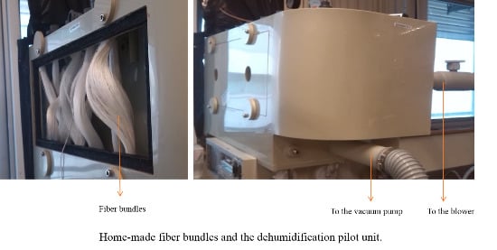
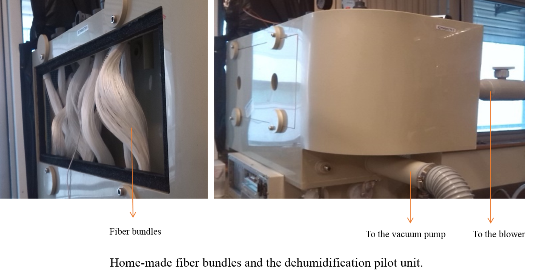
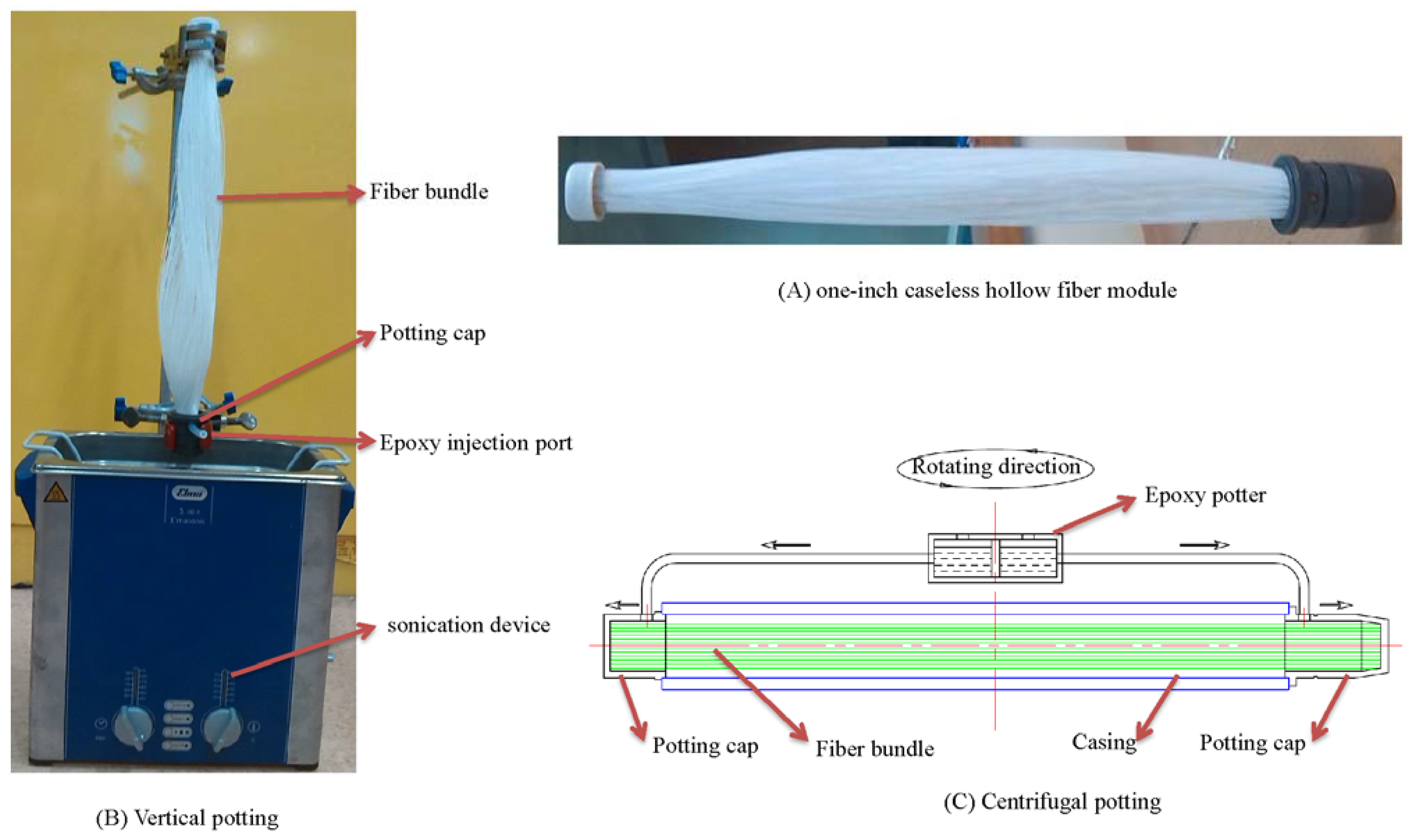
3.1. Hollow Fiber Module Preparation

To maximize the membrane area but to simplify the design and manufacture process of the membrane dehumidifier, the fibers were potted into one-inch diameter bundles without housings like Figure 1A. Each module bundle contains 400 pieces of PAN/PDMS composite hollow fibers with an effective length of 31.5 cm.
Both vertical potting as in Figure 1B and centrifugal potting as in Figure 1C were used in our experiments. By comparison, the vertical potting process is less dependent on the bulky potting apparatus. In this method, the housing filled with hollow fibers was placed vertically and the potting material was injected from the potting cap via single or multiple channels to balance the flow distribution of the potting material. Only one end of the tube sheet was formed at one time during each vertical potting. A sonication device was employed to assure the homogenous distribution of the epoxy during vertical potting, as well as to minimize the potting defects caused by gas bubbles. Centrifuge potting has to be conducted by a centrifuge potting apparatus which usually contains a rotator which rotates about an essentially vertical axis, at least one housing is mounted on the rotator, one pair of potting caps at the ends of the housing, and containers for the potting materials (as shown in Figure 1C). During the potting process, the selected potting material was delivered to the potting caps by the centrifuge force and tube sheets at both ends of the housing could be formed simultaneously.
Figure 1. Vertical potting vs. centrifugal potting.
Membranes 05 00722 g001

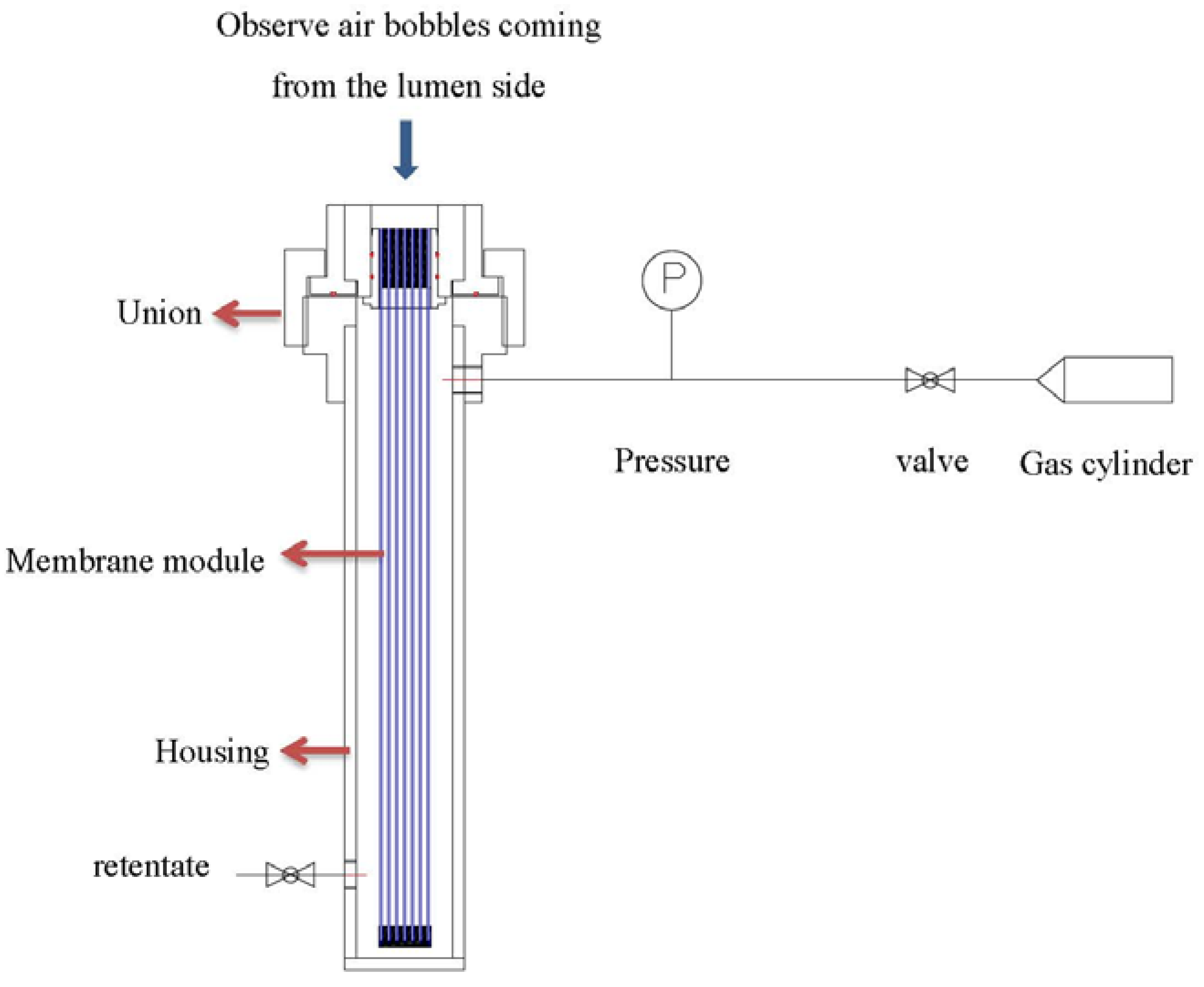
3.2. Leakage Tests and Repair of the Modules

After potting, the leakage was examined by applying soap water on the cross-section of the module’s lumen while pressurizing from the shell side (as in Figure 2). Bubble generation was observed while air is permeating to the lumen side of the fibers. Locations with obviously faster bubble generation were the indicative of defective regions. The leakages of the modules were sealed by epoxy using a needle syringe.
Figure 2. Leaking test of hollow fiber modules.
Membranes 05 00722 g002

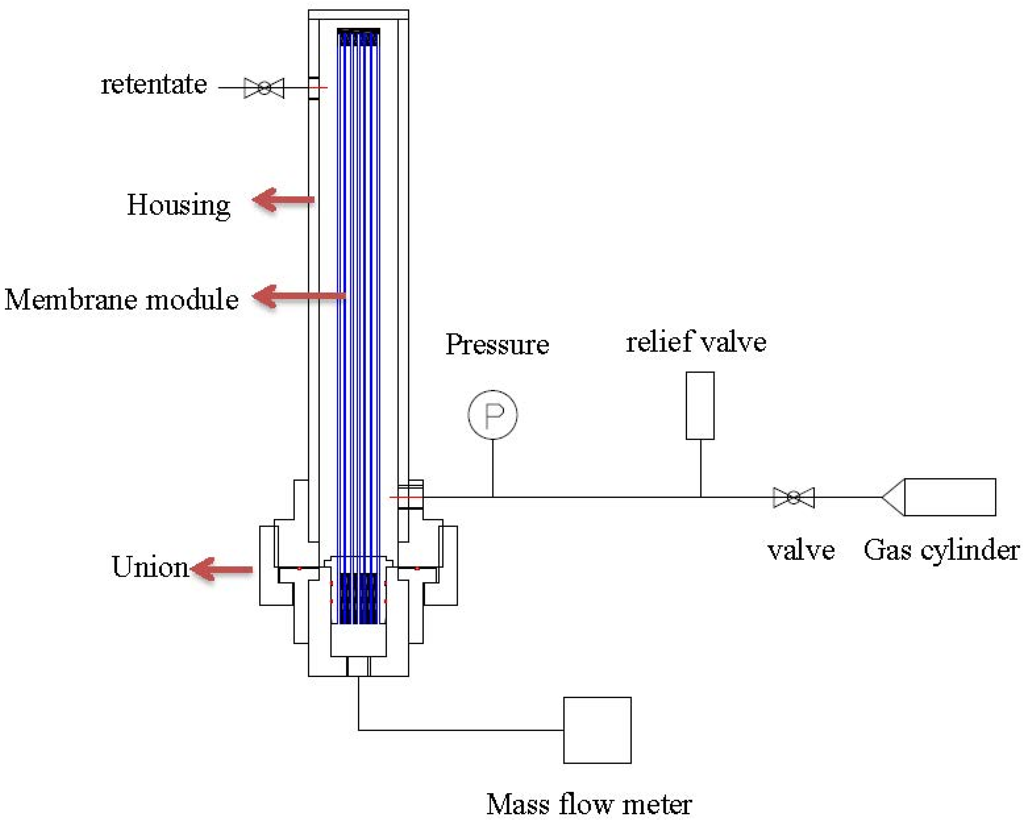
3.3. Pure Gas and Water Vapor Permeance Tests of One-inch Hollow Fiber Modules

After the leakage repaired, each of the hollow fiber bundle was tested by pure gases (O2, N2, and CO2) using the setup as shown in Figure 3. The feed gas pressure was about 1 bar while the permeate flow was measured by a mass flow meter. Water vapor permeance tests were carried out with the same setup in Figure 4. Fresh air was fed into the test apparatus using a blower, while the moisture-rich air permeating from the module lumen was removed by a vacuum pump. The humidity, temperature, flow rate and pressure were measured at both the inlet and outlet of the module. With the aid of the psychrometric chart [42], water vapor concentration D (g/m3) was obtained from the readings of humidity and temperature. The water vapor flow rate (cm3/min) and H2O/N2 selectivity can be calculated using the following equations:
Q = F ( D   D   )
α   = ( P L   ) H O ( P L ) N
where P/L is the water vapor permeance with an unit of GPU (1 GPU = 10 6 cm3 (STP)/(cm2 s cmHg)); Q is the water vapor flow rate (cm3/min); D1 and D2 are water vapor concentrations (g/m3) of inlet and outlet, respectively. F is the humid air flow rate (m3/h); α is the selectivity that is the ratio of the permeances of water vapor H2O and nitrogen gas N2 (pure gas). The water vapor permeance (GPU) can be calculated using Equation (1).
Figure 3. Pure gas test skid of hollow fiber modules.
Membranes 05 00722 g003
Figure 4. Water vapor test skid of hollow fiber modules.
Membranes 05 00722 g004

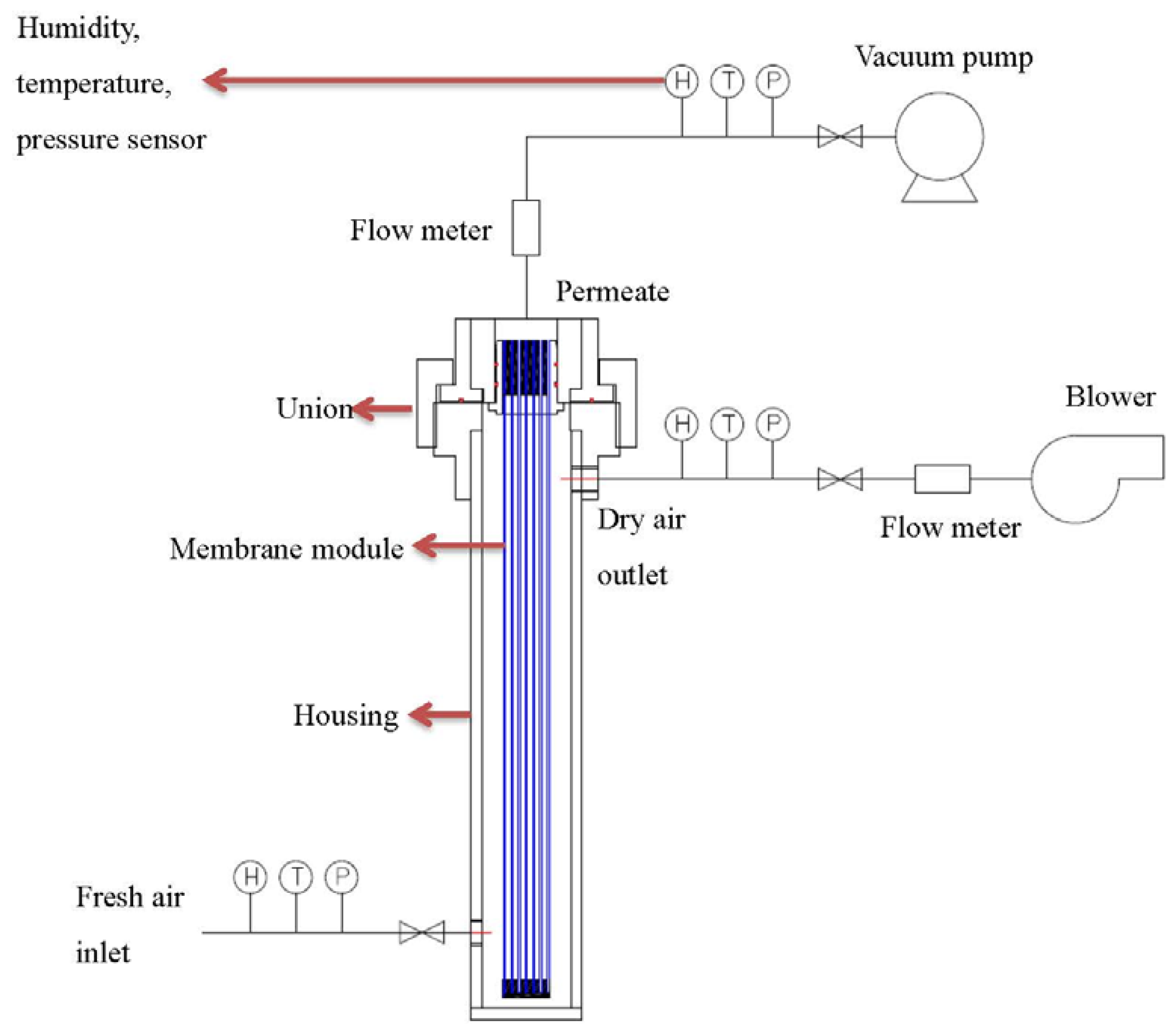
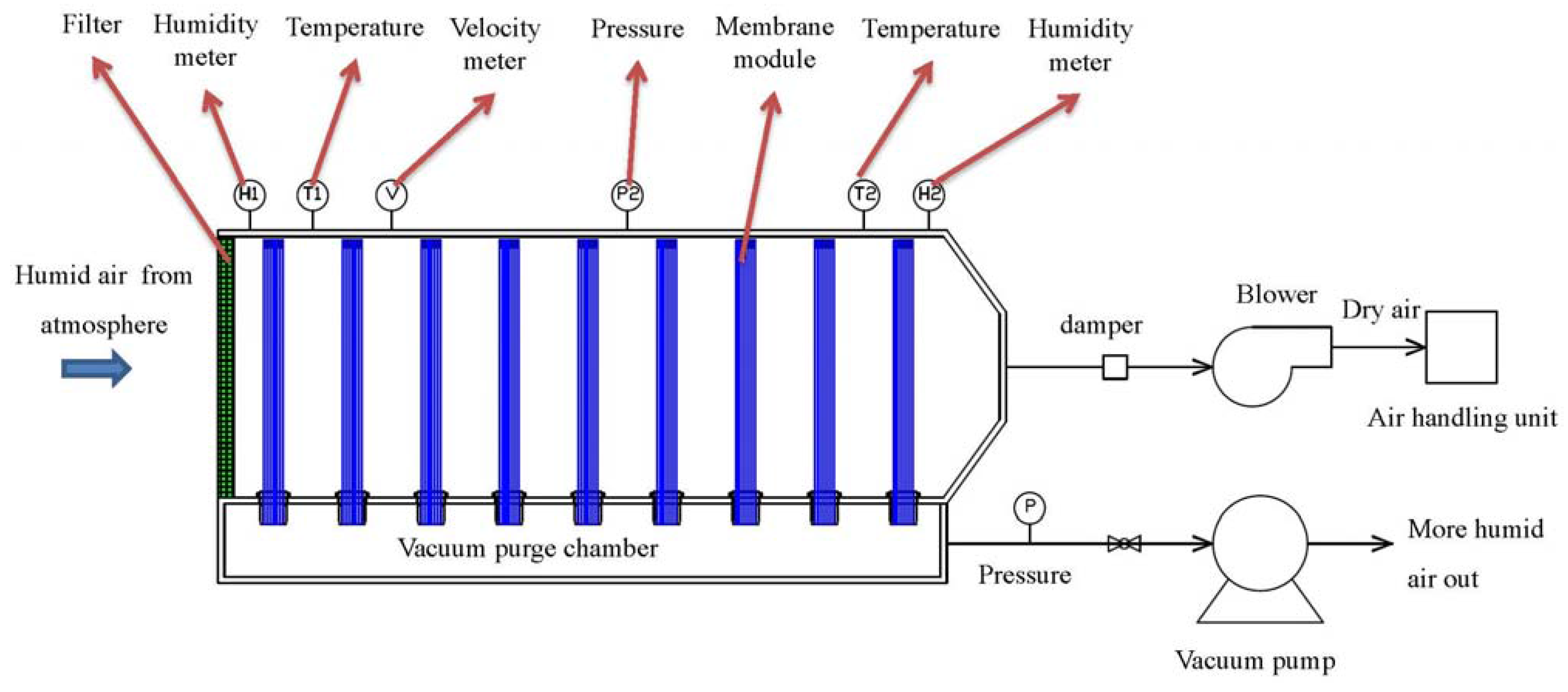
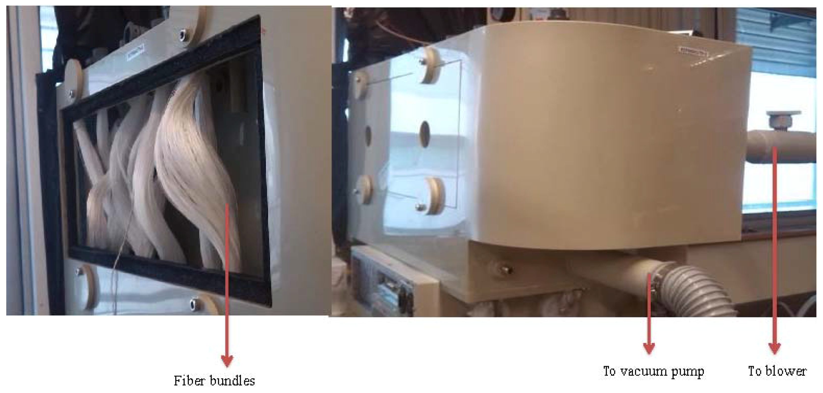
3.4. Design of the Membrane Dehumidification System

The membrane dehumidification system is schematically designed in Figure 5. Nine pieces of one-inch caseless fiber bundles were assembled vertically inside the main chamber. One end of the hollow fiber bundles was sealed while the other end was open and connected to the vacuum purge chamber. During the testing, humid outdoor air was drawn into the membrane dehumidification system by a blower at a flow rate of 200 m3/h. While passing the membrane system, the air moisture permeated through the fibers from the shell side to the lumen side. As a result, the dry air was sent to the AHU, whereas the water moisture was removed out of the system by a vacuum at 0.78 bar absolute pressure from the lumen side of the fibers. A vacuum pump with an output of 1.5 kw, a static vacuum pressure of 230 mbar (0.77 bar absolute pressure), the maximum air flow of 3.1 m3/min were used. A bypass leaking controlled the actual air flow from the system. Thus, the energy of vacuum was E1 = Q 1 Q 1 + Q 2   . P . t = 431.4 KJ where Q1 (permeate air flow from the system) = 5.6 m3/h which included the permeating water vapor and air; Q2 (bypass leaking air flow) = 64.5 m3/h; P (vacuum pump output) = 1.5 kw; t = 3600 s. The pressures, temperatures, and humidity of the inlet and outlet gases were monitored.
Figure 5. Schematic diagram of membrane dehumidification system.
Membranes 05 00722 g005

4. Results and Discussion

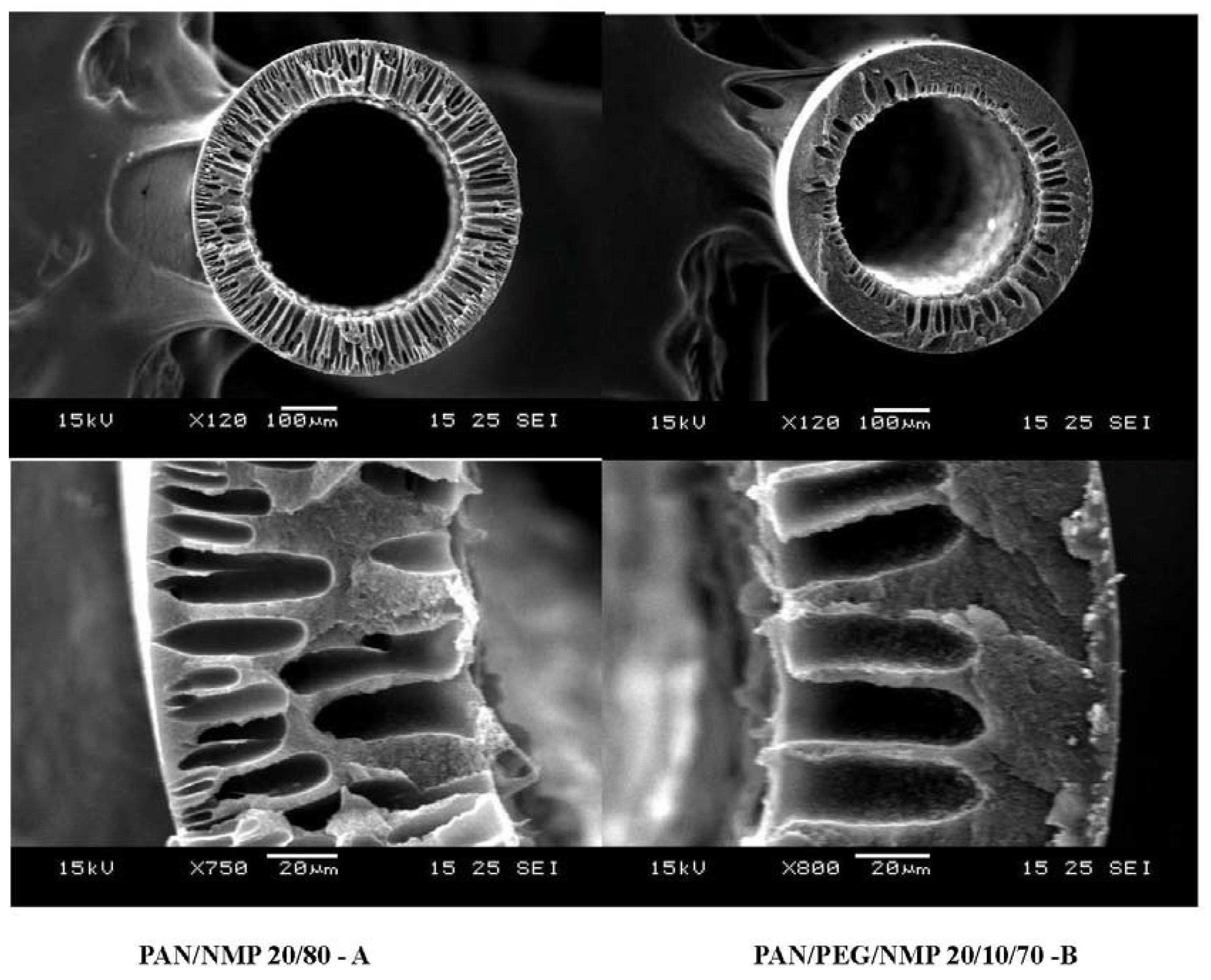
4.1. The Morphology of PAN Substrates

To produce PAN/PDMS composite hollow fibers with the maximum performance, several process parameters such as pre-treatment of the PDMS solution, formulation of the dope solution for the PAN substrate, concentration of the coating solution, effect of pre-wetting, and coating time have been studied. The influence of those parameters on fiber performance have been studied systematically and reported by Li et al. [25] and Chen et al. [43], thus it will not be discussed in the present work. As seen in Table 1, the fiber substrate spun from condition B where PEG was added in the dope formulation has a lower gas permeance possibly because of low cross-section porosity as shown in Figure 6. Therefore, PAN hollow fibers spun from 20/80 PAN/NMP dopes were used for subsequent studies. Table 2 compares the pure gas performance of PAN/PDMS composite hollow fibers as a function of PDMS coating conditions. By using a coating solution of 1% PDMS in hexane, we are able to produce hollow fibers with a CO2 permeance of 1766 GPU. A high concentration of PDMS (>1 wt %) leads to an increase in selective layer thickness, which in turn results in a low gas permeance. Since the ideal CO2/N2 selectivity of all fibers is about the ideal CO2/N2 selectivity of the PDMS dense film [44], therefore the newly developed fibers are considered to be defect-free.
Figure 6. Cross-section morphology of PAN hollow fibers.
Membranes 05 00722 g006
Table 1. Spinning conditions of PAN hollow fibers.
Dope PAN/PEG400/NMP wt %20/0/8020/10/70
Spinneret OD/ID1.6/1.0 mm
Bore fluidNMP/Water 90/10 wt %
External coagulantwater
Coagulant temperature25
Spinning IDAB
Dope flow rate (mL/min)88
Bore fluid flow rate (mL/min)66
Air gap (cm)1919
Take up speed (m/min)3030
O2 permeance (GPU)47,62531,631
N2 permeance (GPU)52,50234,025
Selectivity O2/N20.910.93
Table 2. Coating conditions and pure gas permeation performance of PAN/PDMS fibers.
Hollow Fiber Substrate PAN-20/80
ID of Modules #1#2#3#4#5
Gas Permeation Performance of the PAN Substrate (No Coating)
Gas permeance (GPU)O247,62547,62547,62547,62547,625
N252,50252,50252,50252,50252,502
CO243,06543,06543,06543,06543,065
Concentration of PDMS in Hexane 1%2%3%4%5%
Pre-wetting No
Coating time 1 s1 s1 s1 s1 s
Gas permeance (GPU)O232118018212490
N214381845529
CO2176610751073728375
SelectivityO2/N22.32.22.22.23.1
CO2/N212.413.212.813.212.9

4.2. Pure Gas Permeance and Dehumidification Performance of One-inch Hollow Fiber Modules

Table 3 summarizes the pure gas and water vapor performance of nine pieces of one-inch PAN/PDMS hollow fiber modules. The results show that both the gas permeance and the ideal selectivity of the one-inch bundles are lower than those of single fibers as shown in Table 2. The lower gas permeance is possibly caused by two reasons. Firstly, the PDMS coating is a very sensitive process. During the batch coating of 400 pieces of fibers at the same time, the PDMS coating may not be as effective and homogeneous as compared to a single fiber coating. Secondly, some membrane areas may not be effectively used during the separation (so-called the dead area). The low gas pair selectivity is mainly due to the fact that the batch coating of 400 pieces of fibers is not as efficient and some fibers might be defective. The defective fibers can be repaired by improving the coating precision [45]. However, the process might be complicated, time consuming and expensive. According to Rice and Murphy’s analyses [46], the membranes need not be defect-free to achieve an efficient dehumidification. As long as the membranes have an O2/N2 selectivity of around 1–2, water moisture can still be effectively removed. The testing results of our pilot in the following Section 4.3 will further validate this statement.
Table 3. Pure gas and water vapor permeation performance of 9 pieces of one-inch PAN/PDMS hollow fiber modules.
ID of Module#1#2#3#4#5#6#7#8#9
N2 permeance (GPU)14179513281611887324667
O2 permeance (GPU)2059482400225329123376100
CO2 permeance (GPU)740197273907311786164612184
H2O permeance (GPU)12,82710,78111,22711,34511,04112,707901112,5478647
Selectivity O2/N21.51.21.61.21.41.81.71.51.5
Selectivity CO2/N25.32.55.42.81.94.22.22.52.7
Selectivity H2O/N291.1137.1220.234.668.867.6122.851.1128.6
The pure gas permeation performance was tested by single gas while water vapor permeation performance tested by outdoor humid air.

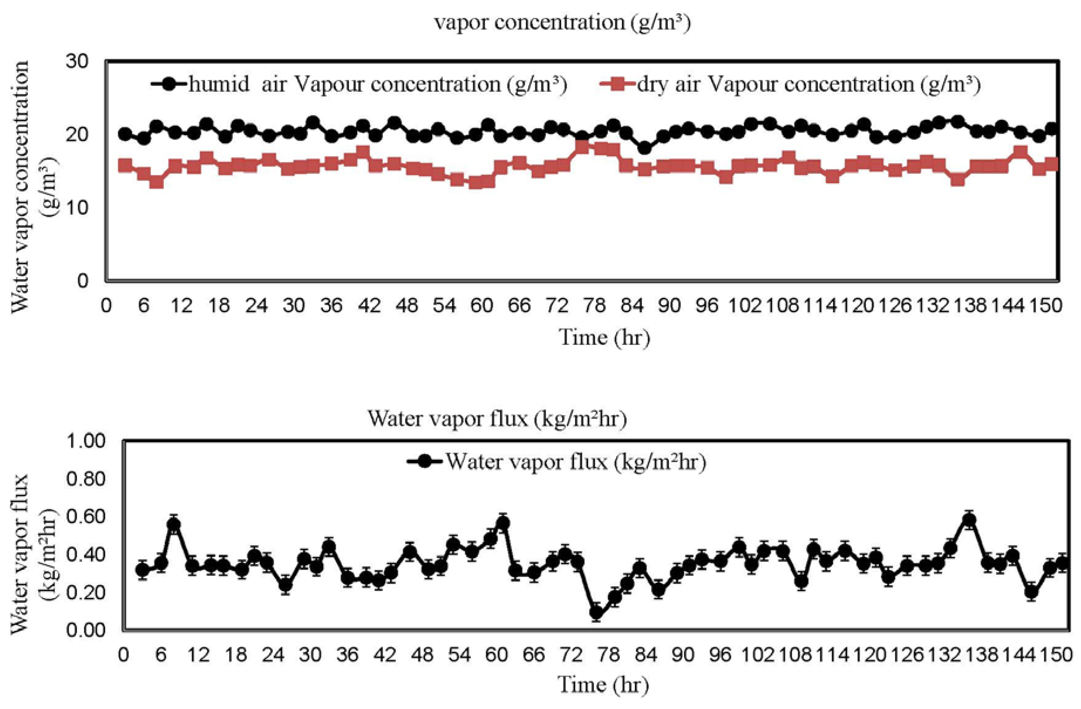
4.3. Membrane Dehumidification Field Tests

To achieve a reasonable gas flux to feed into AHU, more than one piece of hollow fiber modules are required (where the number of hollow fiber modules can be calculated by knowing the effective gas flux per module and the required gas flow by the AHU). When multiple modules are used, they are often connected in parallel or in series. With the objectives to (1) reduce the cost of PVC materials and connection accessories, (2) simplify the module connection, as well as (3) reduce the gas pressure loss inside the connection passages, one-inch hollow fiber bundles without housing and a system comprising nine pieces of one-inch hollow fiber bundles are taken as our design. Figure 7 shows the pictures of our membrane dehumidification system.
Figure 7. Home-made fiber bundles and the dehumidification pilot unit.
Membranes 05 00722 g007
The dehumidification pilot was tested in National University of Singapore. During the test, the feed side of the pilot was located outside the window where fresh outdoor air was directly drawn into the membrane system by a blower. A continuous 150 h test was carried out and the results are plotted in Figure 8. In our test, the inlet fresh air has an average water vapor concentration of 20 ± 2 g/m. After dehumidification, the dry air has an average water vapor concentration of 15.9 ± 2.4 g/m. In other words, about 20.5% of water vapor concentration can be effectively removed by our dehumidification system. This result supports our previous statement that an effective membrane dehumidifier does not require membranes with a high selectivity, but the membranes must have a reasonably high gas permeance. Another interesting observation is the dehumidification performance is stable along the 150 h test.
Figure 8. Water vapor concentration and flux vs. time.
Membranes 05 00722 g008

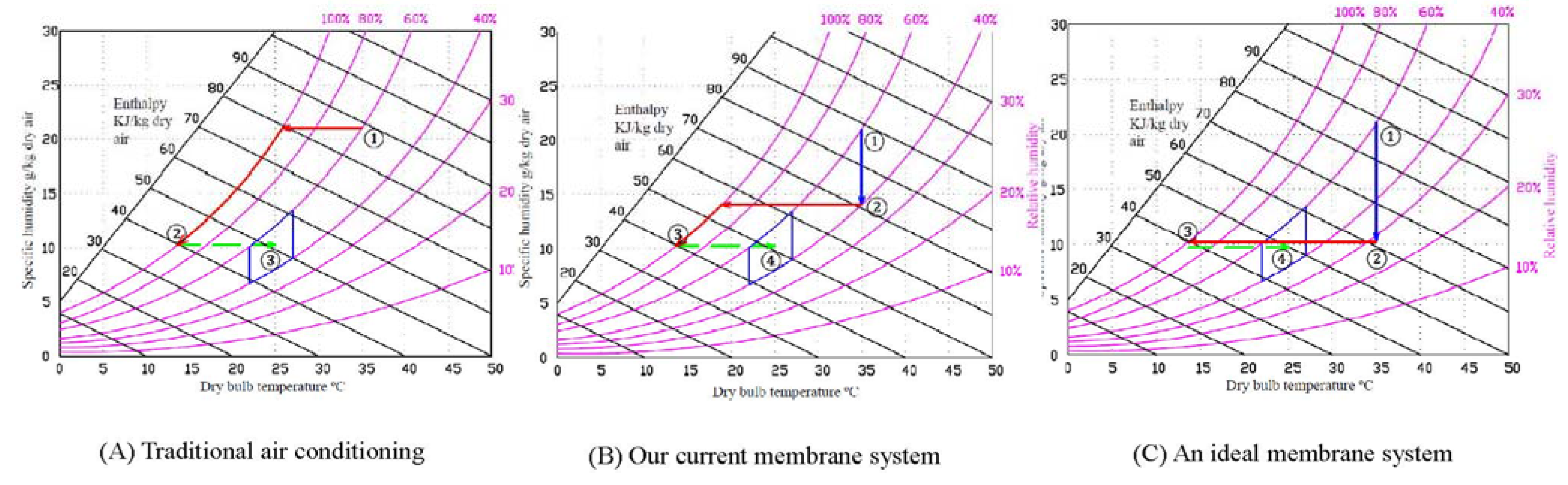
4.4. Calculations on Energy Consumption

With the aid of the psychrometric chart [42] in Figure 9, the energy consumption of different cooling approaches are calculated using the following equations:
E = q . Q . ρ . t C
q = h 1 h 2
where E = Energy consumed in total (KJ),
q = Heat removed (KJ/kg dry air),
h1 = Enthalpy of air (KJ/kg dry air) at point 1,
h2 = Enthalpy of air (KJ/kg dry air) at point 2,
Q = Air flow rate (m3/h),
ρ = Air density (kg/m3),
C = Coefficient of performance (refrigerator),
t = period of time (s)
W1 = Specific humidity (g/kg dry air) at point 1,
W2 = Specific humidity (g/kg dry air) at point 2,
φ1 = Relative humidity at point 1,
φ2 = Relative humidity at point 2
In the following calculations, it is assumed that the temperature and relative humidity of the feed gas is 35 °C and 60%, respectively, while the air flow rate Q = 200 m3/h.
In a traditional air conditioning (Figure 9A), the humid hot outdoor air is directly compressed and cooled down to around 15 °C. To reach the comfort zone for human beings in the indoor environment, the air flow is usually mixed up with hot outdoor air to reach 22 to 27 °C. From the chart, it is read that W1 = 21.75 g H2O/kg-dry-air and W2 = 10.25 g H2O/kg-dry-air; hence, the amount of moisture removed from W1 to W2 is 11.5 g H2O/kg-dry-air. The enthalpy h1 = 88 KJ/kg-dry-air and h2 = 40 KJ/kg-dry-air. Assuming the chiller firstly cools the air to 15 °C, qcool = h1 − h2 = 48 kJ/kg dry air, the coefficient of performance C = 4, t = 3600 s. The energy to mix up the hot air is ignored. The energy consumed for this traditional process is mainly the energy for cooling (i.e., E = 2795 KJ).
Figure 9. Comparison of energy consumption of (A) traditional air conditioning system without dehumidification; (B) air conditioning using our current membrane system; and (C) air conditioning using an ideal membrane system.
Membranes 05 00722 g009
In the ideal case, the humidity of the outdoor can be reduced by a membrane dehumidification system from about 60% to 30% and after that the dried hot air is cooled to 15 °C. The pathway is demonstrated in Figure 9C. From point 1 (60%) to point 2 (30%), the energy consumed is mainly from the energy of vacuum, E1 = Q 1 Q 1 + Q 2   . P . t = 431.4 KJ where Q1 (permeate air flow from the system) = 5.6 m3/h; Q2 (bypass leaking air flow) = 64.5 m3/h; P (vacuum pump output) = 1.5 kw; t = 3600 s. To cool the air from 35 °C to 15 °C, the enthalpy h2 = 60 KJ/kg-dry-air, h3 = 40 KJ/kg-dry-air, qcool = h2 − h3 = 20 kJ/kg dry air. The energy consumed for cooling E2 = 1165 KJ. Thus, the total energy consumed is equal to E = E1 + E2 = 1596.4 KJ. Compared to the conventional air conditioning, using an ideal membrane dehumidifier can save the energy of 42.9%.
Using our current membrane dehumidification pilot, the humidity of the outdoor air is firstly removed to about 40% to 50%. After that, the relatively dried air is cooled down to around 15 °C. Similarly to Figure 9A, the air flow is usually mixed up with outdoor hot air before it is circulated to indoor. The pathway is demonstrated in Figure 9B. This is because our membrane performance and system design has not been fully optimized. 40% is the best RH that can be achieved by our current membrane system.
For the chart, it is read that W1 = 21.75 g H2O/kg-dry-air, W2 = 14.25 g H2O/kg-dry-air, and W3 = 10.25 g H2O/kg-dry-air, the amount of moisture removed from W1 to W2 is 7.5 g H2O/kg-dry-air. During this process, the energy consumed is merely vacuum which is costed by the vacuum pump the same as the ideal case. Hence, the energy consumed in 1 h for dehumidification E1 = 431.4 KJ. Since h2 = 68 KJ/kg-dry-air, h3 = 40 KJ/kg-dry-air, qcool = h2 − h3 = 28 kJ/kg dry air, t = 3600 s. The energy consumed for cooling E2 = 1630.3 KJ. Thus, the total energy consumed is equal to E = E1 + E2 = 2061.7 KJ. In conclusion, the combined use of our membrane dehumidifier together with air conditioning can reduce energy consumption by up to 26.2% compared to conventional air conditioning processes.

5. State-of-Art on Membrane Dehumidification and Conclusions

There are commercial products available on the market for gas separation membranes and membrane modules. Our composite PAN/PDMS membrane has the advantage of cheaper materials costs as compared to polysulfone (PSF) fibers made by Air Product US or Generon UK. Moreover, the newly developed fibers can be operated at a lower pressure with reasonably good performance. Compared to the PDMS fibers made by MedArray via melt spinning, our approach is less energy intensive, specifically during the fabrication process. Using our current hollow fiber membranes and membrane dehumidification system, the energy saving for air conditioning is up to 26.2%. With further improvements of our membranes and membrane modules’ performance, as well as the optimization of the membrane system design, the energy saving of our membrane dehumidifier will be further improved.

Acknowledgments

This research grant is supported by the Singapore National Research Foundation with the project entitled, “Advanced Membrane Air Dehumidifier for Green Building Development” (grant number: R-279-000-412-281) and the “Membranes to remove air pollutants and excess humidity for better indoor air quality and energy saving” (grant number: R-279-000-453-279) under Energy Innovation Research Programme for Building Energy Efficiency (EIRP-BEE) and Building & Construction Authority. Special thanks to Glenn Lipscomb at the University of Toledo and Hangzheng Chen for their great contributions to this project.

Author Contributions

Baiwang Zhao designed and carried out the experiments while Canzeng Liang prepared the hollow fiber membranes. Baiwang Zhao wrote the manuscript. Wai Fen Yong, Peng Na and Tai-Shung Chung refined the manuscript.

Conflicts of Interest

The authors declare no conflict of interest.

References

  1. National Environmental Agency. Climatology in Singapore. Available online: http://www.nea.gov.sg/weather-climate/climate-information/local-climatology (accessed on 25 July 2014).
  2. Human Comfort and Health Requirements. Available online: http://courses.washington.edu/me333afe/Comfort_Health.pdf (accessed on 25 July 2014).
  3. Ito, A. Dehumidification of air by a hygroscopic liquid membrane supported on surface of a hydrophobic microporous membrane. J. Membr. Sci. 2000, 175, 35–42. [Google Scholar] [CrossRef]
  4. Isetti, C.; Nannei, E.; Magrini, A. On the application of a membrane air-liquid contactor for air dehumidification. Energy Build. 1997, 25, 185–193. [Google Scholar] [CrossRef]
  5. Liu, X.H.; Zhang, Y.; Qu, K.Y.; Jiang, Y. Experimental study on mass transfer performances of cross flow dehumidifier using liquid desiccant. Energy Convers. Manag. 2006, 47, 2682–2692. [Google Scholar] [CrossRef]
  6. Zurigat, Y.H.; Abu-Arabi, M.K.; Abdul-Wahab, S.A. Air dehumidification by triethylene glycol desiccant in a packed column. Energy Convers. Manag. 2004, 45, 141–155. [Google Scholar] [CrossRef]
  7. Morgan, W.H.; Bleikamp, L.K.; Kalthod, D.G. Hollow Fiber Membrane Dryer with Internal Sweep. U.S. Patent 5,525,143, 11 June 1996. [Google Scholar]
  8. Matsuura, T. Synthetic Membranes and Membrane Separation Process; CRC Press: Boca Raton, FL, USA, 1993. [Google Scholar]
  9. Paul, D.R.; Yampol’skii, Y.P. Polymeric Gas Separation Membranes; CRC Press: Boca Raton, FL, USA, 1993; pp. 2–84. [Google Scholar]
  10. Nunes, S.P.; Peinemann, K.V. Membrane Technology in the Chemical Industry; Wiley-VCH: Weinheim, Germany, 2006; pp. 1–81. [Google Scholar]
  11. Baker, R.W.; Low, B.T. Gas separation membrane materials: A perspective. Macromolecules 2014, 47, 6999–7013. [Google Scholar] [CrossRef]
  12. Koros, W.J.; Walker, D.R.B. Gas separation membrane material selection criteria: Weakly and strongly interacting feed component situations. Polym. J. 1991, 23, 481–490. [Google Scholar] [CrossRef]
  13. Koros, W.J.; Fleming, G.K.; Jordan, S.M.; Kim, T.H.; Hoehn, H.H. Polymeric membrane materials for solution-diffusion based permeation separations. Prog. Polym. Sci. 1998, 13, 339–401. [Google Scholar] [CrossRef]
  14. Coleman, M.R.; Koros, W.J. Isomeric polyimides based on fluorinated dianhydrides and diamines for gas separation applications. J. Membr. Sci. 1990, 50, 285–297. [Google Scholar] [CrossRef]
  15. McKelvey, S.A.; Clausi, D.T.; Koros, W.J. A guide to establishing hollow fiber macroscopic properties for membrane application. J. Membr. Sci. 1997, 124, 223–232. [Google Scholar] [CrossRef]
  16. Peng, N.; Widjojo, N.; Sukitpaneenit, P.; Teoh, M.M.; Lipscomb, G.G.; Chung, T.S.; Lai, J.Y. Molecular design of polymeric hollow fibers as sustainable technologies: past, present, and future. Prog. Polym. Sci. 2012, 37, 1401–1424. [Google Scholar] [CrossRef]
  17. Chung, T.S.; Kafchinski, E.R.; Vora, R. Development of a defect-free 6FDA-durene asymmetric hollow fiber and its composite hollow fibers. J. Membr. Sci. 1994, 88, 21–36. [Google Scholar] [CrossRef]
  18. Lipscomb, G.G. The melt hollow fiber spinning process: Steady-state behavior, sensitivity and stability. Polym. Adv. Technol. 1994, 5, 745–758. [Google Scholar] [CrossRef]
  19. Matsuyama, H.; Teramoto, M.; Nakatani, R.; Maki, T. Membrane formation via phase separation induced by penetration of nonsolvent from vapor phase. II. Membrane morphology. J. Appl. Polym. Sci. 1999, 74, 171–178. [Google Scholar] [CrossRef]
  20. Tsai, H.A.; Kuo, C.Y.; Lin, J.H.; Wang, D.M.; Deratani, A.; Pochat-Bohatier, C.; Lee, K.R.; Lai, J.Y. Morphology control of polysulfone hollow fiber membranes via water vapor induced phase separation. J. Membr. Sci. 2006, 278, 390–400. [Google Scholar] [CrossRef]
  21. Chung, T.S.; Kafchinski, E.R.; Kohn, R.S.; Foley, P.; Straff, R.S. Fabrication of composite hollow fiber fibers for air separation, J. Appl. Polym. Sci. 1994, 53, 701–708. [Google Scholar] [CrossRef]
  22. Chung, T.S.; Shieh, J.J.; Lau, W.W.Y.; Srinivasan, M.P.; Paul, D.R. Fabrication of multi-layer microporous composite membranes for air separation. J. Membr. Sci. 1999, 152, 211–225. [Google Scholar] [CrossRef]
  23. Peter, J.; Peinemann, K.-V. Multilayer composite membranes for gas separation based on crosslinked PTMSP gutter layer and partially crosslinked Matrimid® 5218 selective layer. J. Membr. Sci. 2009, 340, 62–72. [Google Scholar] [CrossRef]
  24. Verissimo, S.; Peinemann, K.-V.; Bordado, J. Thin-film composite hollow fibre membranes: An optimized manufacturing method. J. Membr. Sci. 2005, 264, 48–55. [Google Scholar] [CrossRef]
  25. Li, P.; Chen, H.Z.; Chung, T.S. The effects of substrate characteristics and pre-wetting agents on PAN-PDMS composite hollow fiber membranes for CO2/N2 and O2/N2 separation. J. Membr. Sci. 2013, 434, 18–25. [Google Scholar] [CrossRef]
  26. Lin, H.Q.; Thompson, S.M.; Serbanescu-Martin, A.; Wijmans, J.G.; Amo, K.D.; Lokhandwala, K.A.; Merkel, T.C. Dehydration of natural gas using membranes. Part I: composite membranes. J. Membr. Sci. 2012, 413–414, 70–81. [Google Scholar] [CrossRef]
  27. Wang, K.L.; McCray, S.H.; Newbold, D.D.; Cussler, E.L. Hollow fiber air drying. J. Membr. Sci. 1992, 72, 231–244. [Google Scholar] [CrossRef]
  28. Lipscomb, G.G.; Sonalkar, S. Sources of non-ideal flow distribution and their Effect on the performance of hollow fiber gas separation modules. Sep. Purif. Rev. 2005, 33, 41–76. [Google Scholar] [CrossRef]
  29. Hao, P.; Lipscomb, G.G. The effect of sweep uniformity on gas dehydration module performance. Membrane gas separation. Ind. Eng. Chem. Res. 2009, 48, 4638–4663. [Google Scholar]
  30. Lemanski, J.; Lipscomb, G.G. Effect of shell-side flows on the performance of hollow-fiber gas separation modules. J. Membr. Sci. 2002, 195, 215–228. [Google Scholar] [CrossRef]
  31. Liu, B.; Lipscomb, G.G.; Jensvold, J. Effect of fiber variation on staged membrane gas separation module performance. AIChE J. 2001, 47, 2206–2219. [Google Scholar] [CrossRef]
  32. Lemanski, J.; Lipscomb, G.G. Effect of fiber variation on the performance of countercurrent hollow fiber gas separation modules. J. Membr. Sci. 2000, 167, 241–252. [Google Scholar] [CrossRef]
  33. Metz, S.J.; van de ven, W.J.C.; Potreck, J.; Mulder, M.H.V.; Wessling, M. Transport of water vapor and inert gas mixtures through highly selective and highly permeable polymer membranes. J. Membr. Sci. 2005, 251, 29–41. [Google Scholar] [CrossRef]
  34. El-Dessouky, H.T.; Ettouney, H.M.; Bouhamra, W. Novel air conditioning system membrane air drying and evaporative cooling. IChemE J. 2000, 78, 999–1009. [Google Scholar] [CrossRef]
  35. Scovazzo, P.; Scovazzo, A.J. Isothermal dehumidification or gas drying using vacuum sweep dehumidification. Appl. Therm. Eng. 2013, 50, 225–233. [Google Scholar] [CrossRef]
  36. Woods, J. Membrane processes for heating, ventilation, and air conditioning. Renew. Sustain. Energy Rev. 2014, 33, 290–304. [Google Scholar] [CrossRef]
  37. Bui, T.D.; Chen, F.; Nida, A.; Chua, K.J.; Ng, K.C. Experimental and modeling analysis of membrane-based air dehumidification. Sep. Purif. Technol. 2015, 144, 114–122. [Google Scholar] [CrossRef]
  38. Peng, N.; Teoh, M.M.; Chung, T.S.; Koo, L.L. Novel rectangular membranes with multiple hollow holes for ultrafiltration. J. Membr. Sci. 2011, 372, 20–28. [Google Scholar] [CrossRef]
  39. Tsai, H.A.; Ciou, Y.S.; Hu, C.C.; Lee, K.R.; Yu, D.G.; Lai, J.Y. Heat-treatment effect on the morphology and pervaporation performances of asymmetric PAN hollow fiber membranes. J. Membr. Sci. 2004, 255, 33–47. [Google Scholar] [CrossRef]
  40. Yang, Q.; Chung, T.S.; Santoso, Y.E. Tailoring pore size and pore size distribution of kidney dialysis hollow fiber membranes via dual-bath coagulation approach. J. Membr. Sci. 2007, 209, 153–163. [Google Scholar] [CrossRef]
  41. Chung, T.S.; Teoh, S.K.; Hu, X. Formation of ultrathin high-performance polyethersulfone hollow fiber membranes. J. Membr. Sci. 1998, 133, 161–175. [Google Scholar] [CrossRef]
  42. Psychrometric Chart and Air-conditioning Processes. Available online: http://www.ohio.edu/mechanical/thermo/Applied/Chapt.7_11/Chapter10b.html (accessed on 25 July 2014).
  43. Chen, H.Z.; Thong, Z.W.; Li, P.; Chung, T.S. High performance composite hollow fiber membranes for CO2/H2 and CO2/N2 separation. Int. J. Hydrogen Energy 2014, 39, 5043–5053. [Google Scholar] [CrossRef]
  44. Metz, S.J. Water Vapor and Gas Transport through Polymeric Membrane. Ph.D. Thesis, University of Twente, Enschede, The Netherlands, 2003. [Google Scholar]
  45. Chen, H.Z.; Xiao, Y.C.; Chung, T.S. Multi-layer composite hollow fiber membrane derived from poly (ethylene glycol) PEG containing hybrid materials for CO2/N2 separation. J. Membr. Sci. 2011, 381, 211–210. [Google Scholar] [CrossRef]
  46. Rice, A.W.; Murphy, M.K. Gas Dehydration Membrane Apparatus. U.S. Patent 4,783,201, 8 November 1988. [Google Scholar]

