Article

Effects of Temperatures and Viscosity of the Hydraulic Oils on the Proportional Valve for a Rice Transplanter Based on PID Control Algorithm

1
Department of Biosystems Machinery Engineering, Chungnam National University, Daejeon 34134, Korea
2
Department of Smart Agriculture Systems, Chungnam National University, Daejeon 34134, Korea
3
Convergence Agricultural Machinery Group, Korea Institute of Industrial Technology, Gimje 54325, Korea
4
Department of Bio-Mechatronics Engineering, Sungkyunkwan University, Suwon 16419, Korea
5
Department of Bio-Industry Mechanical Engineering, College of Industrial Science, Kongju National University, Chungnam 32439, Korea
*
Authors to whom correspondence should be addressed.
Agriculture 2020, 10(3), 73; https://doi.org/10.3390/agriculture10030073
Submission received: 17 January 2020 / Revised: 7 March 2020 / Accepted: 10 March 2020 / Published: 12 March 2020

Abstract

:
This study was conducted to develop a proportional-integral-derivative (PID) control algorithm considering viscosity for the planting depth control system of a rice transplanter using various hydraulic oils at different temperatures and to evaluate the performance of the control algorithm, and compare the performance of the PID control algorithm without considering viscosity and considering viscosity. In this study, the simulation model of the planting depth control system and a PID control algorithm were developed based on the power flow of the rice transplanter (ERP60DS). The primary PID coefficients were determined using the Ziegler-Nichols (Z-N) second method. Routh’s stability criteria were applied to optimize the coefficients. The pole and double zero points of the PID controller were also applied to minimize the sustained oscillations of the responses. The performance of the PID control algorithm was evaluated for three ISO (The International Organization for Standardization) standard viscosity grade (VG) hydraulic oils (VG 32, 46, and 68). The response characteristics were analyzed using statistical method (ANOVA) and Duncan’s multiple range test (DMRT) at a significant level of 0.05 were performed through the statistical software SPSS. The results show that the control algorithm considering viscosity is able to control the pressure of the proportional valve, which is associated with the actuator displacement for various types of hydraulic oils. It was noticed that the maximum pressure was 15.405 bars at 0, 20, 40, 60, 80, and 100 °C for all of the hydraulic oils. The settling time and steady-state errors were 0.45 s at 100 °C for VG 32 and 0% for all of the conditions. The maximum overshoots were found to be 17.50% at 100 °C for VG 32. On the other hand, the PID control algorithm without considering viscosity could not control the planting depth, because the response was slow and did not satisfy the boundary conditions. The PID control algorithm considering viscosity could sufficiently compensate for the nonlinearity of the hydraulic system and was able to perform for any of temperature-dependent viscosity of the hydraulic oils. In addition, the rice transplanter requires a faster response for accurately controlling and maintaining the planting depth. Planting depth is highly associated with actuator displacement. Finally, this control algorithm considering viscosity could be helpful in minimizing the tilting of the seedlings planted using the rice transplanter. Ultimately, it would improve the transplanter performance.

1. Introduction

Transplanters are mainly used to plant grown seedlings on a seedbed for various agricultural crops such as rice, corn, cabbage, soybean, broccoli, and sesame. The world market of rice transplanter is dramatically increasing day by day due to the shortage of daily labor and the aging of the farmers. Goldstein Research [1] reported that the global rice transplanter market is estimated to reach USD 13.06 billion in 2024 from USD 8.07 billion in 2016. Kim [2] stated that the exports of Korean rice transplanter are decreasing compared with the previous year. On the other hand, approximately 6.7% of the farmers in Korea were over 65 years old in 2010, and this is expected to increase to 11.3% in 2050 [3]. Therefore, rice transplanters are an inevitable technology for rice farming. However, transplanters are completely mechanized in Korea, which accounts for 99.9% [4]. The main drawback of the existing transplanters is that they use an on–off valve that is unable to perform precisely. The planting depth control system is one of the crucial working parts of the rice transplanter, which is related to the planting accuracy and yield of rice. Sanusan [5] reported that the planting depth of the seedlings significantly affected the rice yield. Bozorgi [6] also reported that the optimum spacing of the seedling increased rice production. Therefore, precise technology is required for the accurate planting of the seedlings. In addition, the paddy field is not uniformly level, needs a float sensor in the rice transplanter that maintains the planting depth, but the existing rice transplanter using the on–off valve cannot consider the fluctuation of the soil level to plant the seedlings. As a result, the planted seedlings become tilted because of being pressed and pushed in the soil by the float sensor. Therefore, highly precise and modern technologies are required to control the plant depth, which ultimately enhances the performance of the transplanter and meets the farmers’ demand.
Recently, hydraulic proportional valves have been extensively used in most controlling the pressure or flow for automobiles industries [7,8,9,10]. Generally, they are used as flow actuators for hydraulic pistons in a higher level of control loops and for controlling the larger hydraulic valves directly, but a solenoid or an on/off valve cannot directly control this [11,12]. Over the last couple of years, many efforts have been initiated to implement proportional valves in the agricultural machinery for performance improvement. Some of the companies, such as Yanmar, Kubota, and Claas have applied proportional valves to their agricultural machines for precise performance [13,14,15]. Siddique [16] applied proportional valves in a rice transplanter and developed a simulation model for enhancing the performance. Manzone [17] adopted a proportional valve to a hydraulic transmission system for mounting the trailers, in order to protect from damage during operations. The proportional valve was also adapted to the power shuttle system of a tractor in order to control the pressure for clutch actuation [18]. He also reported that the proportional valve actually performed so as to control the engage and disengage of the clutch. Foster [19] developed a velocity control system applying the proportional valve for a self-propelled windrower. The results indicated that the proportional valve displaced the pintel arms equally. A hydraulic actuator and proportional valve were also applied to the precision agriculture like liquid manure applications. Saeys [20] developed a depth control system for a tractor using a proportional valve in order to regulate the actual working depth of the rotary implements. He also mentioned that a hydraulic actuating system was a common approach in agriculture. Saeys [21] also used the proportional valve to splay liquid manure precisely. Therefore, the proportional valve was implemented to control the planting depth of a rice transplanter for enhancing the performance.
However, proportional valves are highly nonlinear, which impacts the accuracy, stability, and performance of the hydraulic system [22,23,24]. Temperature is the main reason for the nonlinearity of a hydraulic system, and oil temperature is the most important parameter for increasing the performance of the hydraulic system. This is because the oil temperature is closely related to the variation of oil viscosity and the leakage of the hydraulic system, which greatly influences the damping ratio of the proportional valve and makes the system unstable [25,26]. Chen and Wang [27] reported that the temperature of the hydraulic oil may change the viscosity, vapor pressure, and bulk modulus of the system. Javalagi and Singireddy [28] reported that the performance of the hydraulic system depends on the viscosity of the hydraulic oil. Therefore, a control algorithm was applied in the model to control the hydraulic system, as it was highly nonlinear as a result of the temperature of the hydraulic oils. This study is focused on controlling the pressure of the proportional valve because the supplied pressure of the valve is associated with the actuator movement. The planting depth depends on the actuator movement. To control the pressure of the proportional valve, a control algorithm is important for controlling the planting depth of the rice transplanter uniformly and precisely.
Nowadays, a model-based control algorithm such as the proportional-integral-derivative (PID) is widely used to control the nonlinearity of the hydraulic system [29,30,31,32,33,34]. In addition, the PID control algorithm is comparatively easier to design as a model–based control algorithm [35], and to determine the PID coefficients, one can use Ziegler-Nichols (Z-N) methods [36]. Anthonis [37] developed a PID control algorithm for an automatic depth control system so as to maintain the cutting depth as constant as possible. Condon [38] developed a PID control algorithm for a depth control system for a peat milling machine. An on-off control algorithm was designed for controlling the depth of the rotary implements [39]. Søgaard [40] developed an automatic control algorithm for a finger weeder in order to keep the constant working depth and to minimize vibrations from the soil. Weatherly and Bowers [41] also developed a proportional control algorithm for controlling the seeding depth of a seed planter. As every machine has its own dynamics properties, a new machine needs a new control algorithm. Therefore, Siddique [42] developed a PID control algorithm for controlling the planting depth of a rice transplanter based on the actuator displacement, without considering the viscosity. Because the actuator displacement of the rice transplanter is directly associated with planting performance, the uniformity and actuator displacement depends on the flow rate of hydraulic oils [43]. As the viscosity change of the hydraulic oils has a great influence on the flow rate, the effects of the viscosity and temperature of the hydraulic system are the main concerns for controlling the hydraulic actuator displacement of a rice transplanter.
The purpose of this study to develop a new control algorithm considering various hydraulic oil viscosities at a reference temperature. The viscosity of various hydraulic oils varies at different grades of hydraulic oils. There are very little researches that have been conducted considering the viscosity of various hydraulic oils, especially for agricultural machinery. In this study, various ISO (The International Organization for Standardization) standard hydraulic oils, available in the local market in Korea, were used to perform the PID control algorithm. Park [44] reported that the response of the hydraulic system delays at initial operation because of the high viscosity of the hydraulic oils at low temperatures. This is why the proportional valve should supply the accurate pressure to the automatic depth control system of a rice transplanter. Therefore, the specific objectives of this study are as follow: (i) to develop a PID control algorithm of the planting depth control system of a rice transplanter; (ii) to determine the PID coefficients considering the hydraulic oil viscosity at different temperatures; and (iii) to evaluate the response characteristics of PID control algorithms.

2. Materials and Methods

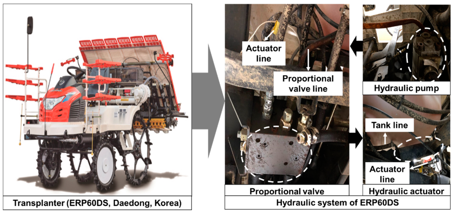
2.1. Rice Transplanter

The rice transplanter (ERP60DS) is a six-row diesel rice planting machine, manufactured commercially by Daedong Industrial Company, Korea. ERP 60DS is a highly efficient planting machine designed for almost 1.7 m/s, which reduces the working time. The fuel consumption of this rice transplanter has excellent efficiency, accounting for around 2754 g/kWh, which is economically friendly for farmers. The hydraulic pump and proportional valve were designed for high accuracy, and the constant movement of the hydraulic actuator ensures the precise planting depth of the rice seedlings and the efficiency of the rice transplanter. It also helps to minimize the tilting problem of rice seedlings.
The main components of the rice transplanter’s hydraulic system are the hydraulic pump, proportional valve, and hydraulic actuator. The hydraulic pump, which has a 4.5 cc/rev displacement, generates hydraulic pressure by operating the engine and supplies to the proportional valve. The proportional valve controls the pressure according to the command of the float sensor. The operating pressure and flow of the proportional valve are 20 MPa and 15 LPM, respectively. The hydraulic actuator adjusts the movement based on the control pressure of the proportional valve. The piston and rod diameter of the actuator are 55 and 15 mm, respectively and this actuator movement is the planting depth. Ultimately, the proportional valve helps to control the uniform planting depth of a rice transplanter. The rice transplanter and its main hydraulic components are shown in Figure 1.

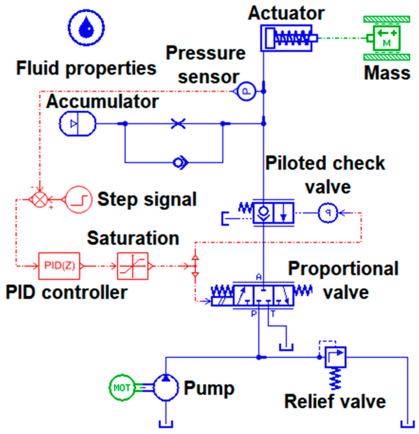
2.2. Simulation Model of the Planting Depth Control System

The planting depth control system of the rice transplanter is developed and simulated by LMS AMESim (version 16, Imagine S.A. Company, France). The simulation model was developed based on the power flow of the planting depth control system using the hydraulic proportional valve for enhancing the comprehensive performance of the rice transplanter. The power flow of the simulation model was considered on the basis of a real rice transplanter (ERP 60DS, Korea). The simulation model of the automatic planting depth control system was to control the pressure for both without considering and considering the viscosity of the hydraulic oil. The control algorithm was applied using MATLAB Simulink (The MathWorks, Inc., Natick, MA, USA), which is shown in Figure 2.
The flow was generated by the hydraulic pump and was supplied to the proportional valve. The supplied pressure from the proportional valve controlled the movement of the hydraulic actuator. In this model, there was an accumulator to reserve the flow for an emergency flow supply to the hydraulic actuator. Also, the pilot check valve was used in this model, which helped to hold the hydraulic actuator at any position. Using the pilot check valve, the transplanter could stop the planting device at any depth or height.
The simulation model of the planting depth control system of the rice transplanter was composed of a 4.5 cc/rev and a 2650-rated rotational speed hydraulic pump for generating the flow and supplying it to the proportional valve. The proportional valve, which had a 20 MPa operating pressure was used to regulate the hydraulic actuator movement. The piston and rod diameters of the hydraulic actuator were 55 and 15 mm. The planting depth of the rice seedling directly depended on the actuator movement that was controlled by the proportional valve. Also, the hydraulic actuator was used for balancing the load of the proportional valve.

2.3. Design of the PID Control Algorithm

In this section, the PID algorithm considering viscosity was developed and another PID algorithm without considering viscosity [42] was summarized shortly to compare the performance of both PID algorithms. Actually, the PID control algorithm without considering viscosity was designed to control the displacement of the hydraulic actuator and the hydraulic oil viscosity was not considered to determine the PID coefficients.

2.3.1. PID Control Algorithm without Considering Viscosity

In general, the single-acting actuator control algorithm was developed considering the flow rate, supply pressure, damping ratio, and natural frequency of the proportional valve. Recently, single-acting actuators have been getting priority over the double-acting actuators for being simple and cost-effective. Also, they can minimize size and optimize space [45]. Figure 3 shows the proportional-integral-derivative (PID) control algorithm for position control without considering viscosity [42]. The control plant was designed by the second-order transfer function.

2.3.2. PID Control Algorithm Considering Viscosity

To develop the PID control algorithm considering viscosity, the mathematical model for a single-acting actuator and proportional valve was designed considering the third-order transfer function. The hydraulic actuator and proportional valve model are shown in Equation (1). The details derivations were discussed [42].
G ( s ) = K input A   ω n 2 s ( s 2 + 2   ζ ω n s   +   ω n 2 ) ,
where G(s) is the transfer function of this system, which is a ratio of input and output; s is the s-domain function of Laplace transfer; A is the cylinder area (m2); Kinput is the input signal of the proportional valve; ζ is the valve damping ratio; ω n is the valve natural frequency of proportional valve which is denoted by Hz, and Kinput/A is calculated as 0.02 [42].
In this study, the natural frequency (ωn) was considered to be 5 Hz to calculate the actuator transfer function, and the damping ratio was the variable used to find the primary PID coefficients because the viscosity of the hydraulic oils affected the damping ratio. According to Amirante [46], the range of natural frequency of a commercial proportional valve is 20 to 85 Hz for the stabilization of the system. This is because the lower natural frequency of the proportional valve has no resonance peak, and the resonance phenomena are important to realize a precise and accurate control system. The PID controller has also its own transfer function, shown in Equations (2)–(4).
G c ( s ) = K p ( 1 + 1 T i s +   T d s ) ,
G c ( s ) = 0.6 K cr ( 1 + 1 0.5 P cr s + 0.125 P cr s ) ,
G c ( s ) = 0.075 K c r P c r ( s + 4 P c r ) 2 s ,
where Gc (s) is the transfer function of the PID control algorithm; Kp, Ti, and Td are the coefficients of the proportional, integral, and derivative, respectively; Kcr is the critical proportional gain, which is determined by the Routh array, and the corresponding critical period.
P cr = 2 π ω cr ,
where Pcr is the corresponding critical period, and ωcr is the frequency of sustained oscillations.
To find the frequency of the sustained oscillation, s = jω was substituted into the characteristic equation of the plant. From Equation (5), the PID control algorithm had a pole at the origin and double zeros at s = −4/Pcr. The closed-loop transfer function can be obtained by considering Ti = ∞ and Td = 0. The closed-loop transfer function is shown in Equation (6).
C ( s ) R ( s ) = K p s 3 + 8 s 2 + 25 s + K p ,
Thus, the characteristic equation of the closed-loop was found from Equation (6), as shown in Equation (7).
R ( s ) = s 3 + 8 s 2 + 25 s + K p ,
The selection of PID coefficients is important to design the PID controller [47]. Therefore, the Ziegler-Nichols (Z-N) second method was applied to select the PID coefficients at various damping ratios of the unit step response of the control algorithm. This is because the Z-N second method does not require the processed model. Kp, Ti, and Td were determined using Equations (8)–(10).
K p = 0.6   K cr ,
T i = 0.5 P c r ,
T d = 0.125 P c r ,
To control the pressure of the proportional valve, a PID (Proportional-Integral-Derivative) controller was designed by MATLAB Simulink. The PID control algorithm considering viscosity is shown in Figure 4.

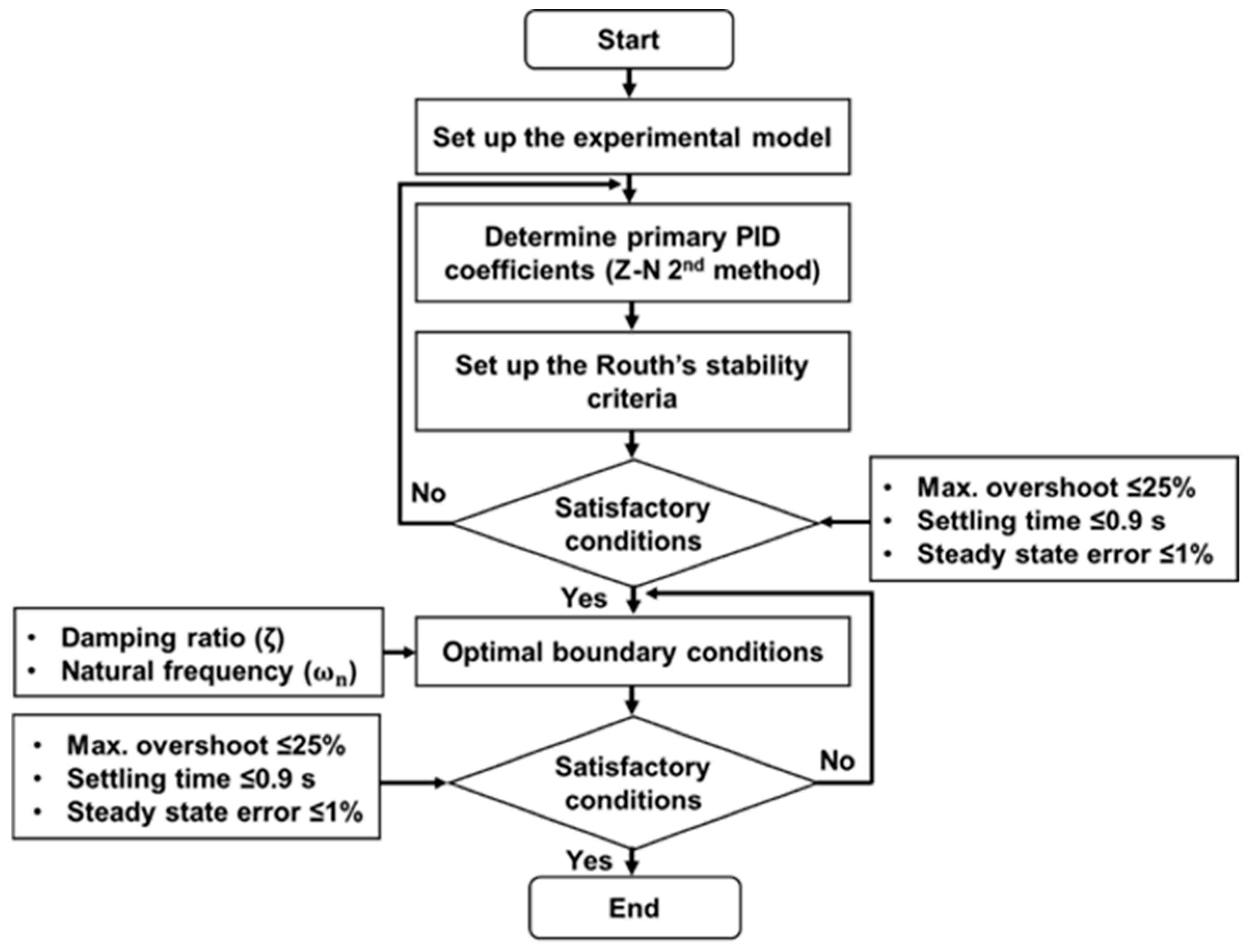
2.4. Initial Coefficients of PID Control Algorithm Considering Viscosity

Figure 5 shows the unit step response at various damping ratios. The range of the damping ratio was selected for a wide range from underdamped to overdamping such as 0.4, 0.6, 0.8, 1.0, and 1.2. The best results were found at 0.8, which is an underdamped condition. The unit step response at a damping ratio of 0.8 had the lowest overshoot (57%), and settling time (2.8 s), which was excessive for a rice transplanter. The primary PID coefficients were selected by analyzing the response characteristics of the step responses. Routh’s stability criteria were applied to minimize the sustained oscillation of the response.

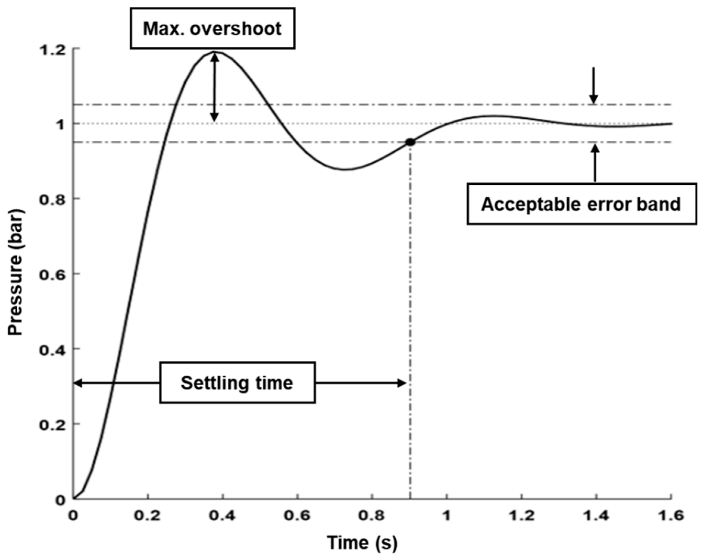
2.5. Performance Evaluation of the Control Algorithms

Figure 6 shows the boundary conditions and control strategies of the PID algorithm. First, the experimental model was set up to determine the primary PID coefficients using the Z-N second method. Second, the Routh’s stability criteria were applied to minimize the overshoot and sustained oscillations. Third, the boundary conditions were applied. If the response satisfied the conditions, it will be further verified after applying optimal boundary conditions. If the response is not satisfied with the conditions, the primary coefficients should be determined again.
The planting depth control system of the rice transplanter is highly precise technology. It requires a faster rise for precisely and uniformly planting of the seedlings. Therefore, the settling time of the response was considered to be less than or equal 0.9 s, and the maximum overshoot was less than or equal to 25% [36]. The target value of the maximum overshoot (≤25%) means that if the overshoot is increased over 25%, the control algorithm will not have satisfied the response. On the other hand, the hydraulic actuator of the transplanter cannot move linearly. Also, this control algorithm cannot control the planting depth of the transplanter. In the case of the settling time, the target value was considered to be less than or equal 0.9 s in order to determine the primary PID coefficient. The boundary condition of the control algorithm indicates that this control algorithm is able to perform for the designed model within the restricted ranges. Also, the lower settling refers to the better performance of the model. However, the settling time (0.9 s) is enough to determine PID coefficients for the automatic depth control system of a rice transplanter. The higher settling time also affects the planting performance of the transplanter [48]. The steady-state error, which is another important character to control the planting depth control system, was considered to be less than or equal to 1% [49]. Therefore, the responses characteristics of both control algorithms should satisfy the boundary conditions or target values, in order to minimize the tilting problem of the automatic planting depth control system and improve the performance of transplanter.
In this study, three ISO standard hydraulic oils available in the Korean local market for agricultural machinery namely Kixx RD HD (VG 32, 46, 68) were selected to determine the PID coefficient. As the highest temperature of agricultural machinery hydraulic oil is 100 °C for all-weather conditions [50], the temperature range was divided into five levels of equal intervals (0, 20, 40, 60, 80, and 100 °C). The viscosity of the selected hydraulic oils is shown in Figure 7.
The viscosity of the hydraulic oil is inversely proportional to the temperature. Park [44] reported that the pressure of hydraulic oils cannot occur at a low temperature because of the high viscosity. When the temperature of the hydraulic oil is increased, the molecules of the hydraulic oil slide over each other easily making the oils less viscous [51,52] and transmitted the power. These types of hydraulic oils are most commonly used in Korea for agricultural machinery. The specifications of the hydraulic oils are provided by the manufacturer. The pour point indicates the minimum temperature at which fluid loses its fluidic characters and the flashpoint is the minimum temperature at which the fluid starts to vaporize to form an ignitable mixture in air. The specifications of the selected hydraulic oils are listed in Table 1.

2.6. Analysis Methods

To analyze the effects of temperatures on the PID control algorithm of the proportional valve, the temperature range should be specified at which the simulation was carried out for various hydraulic oils. In this study, the performance of the PID control algorithm at the selected temperature ranges was conducted repeatedly for the hydraulic oils (VG 32, 46, and 68). The statistical analysis, one-way ANOVA (Analysis of Variance) and Duncan’s multiple range test (DMRT) at a significant level of 0.05 were performed through the statistical software IBM SPSS Statistics (SPSS 25, SPSS Inc., New York, USA) in order to compare the performance of the PID control algorithm considering and without considering viscosity.

3. Results and Discussion

3.1. PID Coefficients for PID Control Algorithm Considering Viscosity

The PID coefficients of the control algorithm considering viscosity were determined at a damping ratio of ζ= 0.8 of the proportional valve, using the pole of origin and double zero points of the PID control algorithm. Routh’s stability criteria were also applied to minimize sustained oscillations. The selected coefficients were Kp = 15, Ti = 10.75, and Td = 0.43. The settling time and maximum overshoot were calculated as being approximately 0.90 s and 19.90%, respectively, and the steady-state error was found to be 0% (zero). The response of the PID control algorithm considering the viscosity of the hydraulic oils is shown in Figure 8.
The coefficients of the control algorithm with its response characteristics are listed in Table 2. From these results, the coefficients of the control algorithm satisfied the boundary conditions. The boundary conditions are the maximum overshoot (≤25%), settling time (≤0.90 s), and steady-state error (≤1%) [36,48,49]. It is important to analyze the response characters of the control algorithm for various hydraulic oils in order to select the best PID control algorithm for controlling the pressure of the model.

3.2. Performance of PID Control Algorithms

The performance of the PID control algorithm without considering viscosity was conducted for various hydraulic oils at six levels of temperatures, which is shown in Figure 9a–c. It was noticed that the pressures of the proportional valve for all types of hydraulic oils and all levels of temperatures (0, 20, 40, 60, 80, and 100 °C) smoothly increased and it took comparatively longer to become stable and stay at a constant pressure. It was observed that the maximum pressure of the proportional valve was around 15.405 bar at 100 °C for VG 32 for the lowest viscosity of the hydraulic oil. The pressure of the proportional valve was gradually decreased as the viscosity of the hydraulic oils increased. It was noticed that the overshoot and steady-state error appeared at the higher viscosity means at a lower temperature of the hydraulic oils. It also required a higher settling time.
The results show that pressures at different temperatures were almost same (Figure 9). However, the responses of the proportional valve were too slow to control the pressure. Also, the steady state errors were found that effect the performance of control algorithm. The response time and error are most critical issue to satisfy the control performance and accuracy [53,54,55] and the overshoot effects on durability and longevity of the proportional valve [56]. Therefore, the response characters of the proportional valve should satisfy the boundary conditions of the control algorithm.
It is observed that the temperatures’ effects on pressures have significantly different for all hydraulic oils at 30, 40, 60, and 80 °C. The detailed results of proportional valve pressure according to the different temperatures of the hydraulic oils with ANOVA using DMRT are summarized in Table 3. It was statistically proved that below 20 °C and above 80 °C of the hydraulic oils, there was no significant difference between the pressure. Results found that the pressures were the same at 20 °C or below due to the higher viscosity. In the case of low viscosity above 80 °C of the hydraulic oils, the pressures of the proportional valve also remained the same. These results revealed that the PID control algorithm without considering viscosity cannot control the pressure of the proportional valve.
On the other hand, Figure 10 shows the performance of the control algorithm considering the viscosity of the hydraulic oils. The pressure of the proportional valve suddenly rose to a peak after 0.40 s, and had a 5% acceptable error band [47], as shown in Figure 10a–c. At 0 °C for the hydraulic oils (VG 32, 46, and 68), the response was a little slow compared with the other temperature levels of the hydraulic oils. It took a maximum of 0.45 s to be stable. The maximum pressure of the proportional valve was around 15.405 bar at each temperature of the hydraulic oils. Subsequently, the automatic depth control system became stable and was sustained at a constant value.
It was also observed that the PID control algorithm considering viscosity of the hydraulic oils responses quickly for finding the target value. It is clear that the pressure of the proportional valve was constant for changing the viscosity of the hydraulic oils with respect to the temperatures. It indicated the linear movement of the hydraulic actuator. It was also noticed that only the response characteristics were different. Therefore, the response characters of the proportional valve were analyzed.
The response characteristics of the proportional valve were analyzed with one-way ANOVA using DMRT. The summarized results are shown in Table 4. The response of the PID control algorithm without considering viscosity had a lower overshoot at a higher viscosity of the hydraulic oils than that of the PID control algorithm considering viscosity. The overshoot of the PID control algorithm without considering viscosity was calculated to be around 3.85% and 3.48% at 80 and 100 °C of hydraulic oils for VG 32, VG 46, and VG 68, respectively. At 0, 20, 40, and 60 °C for the hydraulic oils, the overshoots were found to be 0%. However, when the higher settling time appeared, accounting for 4 s which is exceeded the boundary condition (≤0.9 s) of the control algorithm at 0 and 20 °C for all types of oils (VG 32, 46, and 68). In the case of the other temperatures (40, 60, 80, and 100 °C), the responses stayed at an acceptable error band within 2.70 s, which was also larger than the boundary conditions. This means that the float sensor of the transplanter might be delayed when sending a signal to the proportional valve for lifting up and down. It decreased the planting accuracy of a rice transplanter. Also, there was a steady-state error at 0 and 20 °C for VG 32, 46, and 68, accounting for 1% and 0.94%, respectively. The steady-state errors were 0% for the other levels of temperatures (40, 60, 80, and 100 °C). This indicates that the planting depth control system of a rice transplanter had many errors when planting the rice seedling. It could tilt the planted seedlings. As the planting depth control system required a faster response to avoid the tilting problem, this means that the PID control algorithm without considering viscosity is not applicable for the automatic planting control system of a rice transplanter.
In the case of the PID control algorithm considering viscosity, the maximum overshoot was 17.50% for VG 32 at a 100 °C temperature. The notable discrimination is that the overshoot of the PID control algorithm considering viscosity is higher than the PID control algorithm without considering viscosity. However, the maximum overshoot was found to be 25% for the four raw corn planters [49]. The minimum overshoot was 0% at 0 °C for all types of hydraulic oils. The boundary condition for the maximum overshoot for the automatic planting depth control system of a rice transplanter was less than or equal to 25%. A possible reason was that the control algorithm was tuned to rise very fast, as is required for the automatic depth control system of a rice transplanter. Foster [19] stated that the overdamping system also makes a higher overshoot and a faster response. However, the maximum overshoot satisfied the boundary condition or target value of the PID control algorithm considering viscosity.
The statistical analysis shows that the response characteristics of the proportional valve were significantly different between the two control algorithms. It is clear that the settling time and steady-state error of the PID control algorithm without considering viscosity were the biggest difference with the PID control algorithm considering viscosity. Through the overshoot of the PID control algorithm considering viscosity was comparatively higher but enough to control the pressure.
Generally, the maximum overshoot affected the dynamic properties of the proportional valve and hydraulic actuator. It decreased the life cycle of the proportional valve and hydraulic actuator. If the maximum overshoot increased over the boundary condition, the proportional valve could be damaged. However, the maximum settling time was 0.45 s at 0 °C, which was less than the boundary condition (≤0.9 s) of the control algorithm at all temperatures of the hydraulic oils. This means the proportional valve was able to properly control the planting depth of the rice seedlings. If the settling time was higher than the boundary condition, the rice transplanter could not control the desired depth of seedlings and tilt the planted seedlings. The steady-state error was found to be 0% at any temperature level for any type of hydraulic oil, which was also less than the boundary condition (≤1%). This means that the PID control algorithm considering viscosity satisfied all of the boundary conditions for the automatic depth control system of a rice transplanter. The response characters are listed in Table 3. These results indicate that the PID control algorithm considering viscosity is feasible for controlling the planting depth of rice seedlings.
Also, He [49] applied a PID control algorithm for four raw corn planter to control the seed plate rotation speed for the seed meter’s response and planting quality. He also reported that a faster response is important for improving planting quality and accuracy. In this study, the maximum overshoot was accepted to be 26.10%. Therefore, the PID control algorithm considering viscosity could be adaptable for the automatic depth control system of a rice transplanter for any kind of the hydraulic oils and their reference temperatures and could result in the quality of the planting seedling and the accuracy.

4. Conclusions

This study is mainly focused on the development of a PID control algorithm considering the temperature-dependent viscosity of the hydraulic oils for the pressure control of the proportional valve. First, the simulation model of the planting depth control system and the PID control algorithm were developed based on the power flow of the rice transplanter. Second, the primary PID coefficients were determined by the Ziegler-Nichols (Z-N) second method and optimized by Routh’s stability criteria. The pole at the origin and double zero points were also applied to minimize the sustained oscillation of the response. Third, the control algorithms were evaluated for three ISO standard hydraulic oils. In this study, the proportional valve is applied in the planting depth control system of the rice transplanter in order to enhance the comprehensive performance by controlling the pressure of the proportional valve and the displacement of the actuator, and results are as follows.
  • The PID control algorithm without considering viscosity shows a higher settling time than the boundary condition for various hydraulic oils. Therefore, this control algorithm cannot control the automatic depth control system.
  • In the case of the control algorithm considering viscosity, the PID coefficients were determined to be Kp = 15, Ti = 10.75, and Td = 0.43 at a damping ratio of ζ= 0.8. The maximum overshoot and settling time of the primary response were almost 19.90% and 0.90 s, accordingly, whereas the steady-state error was 0%.
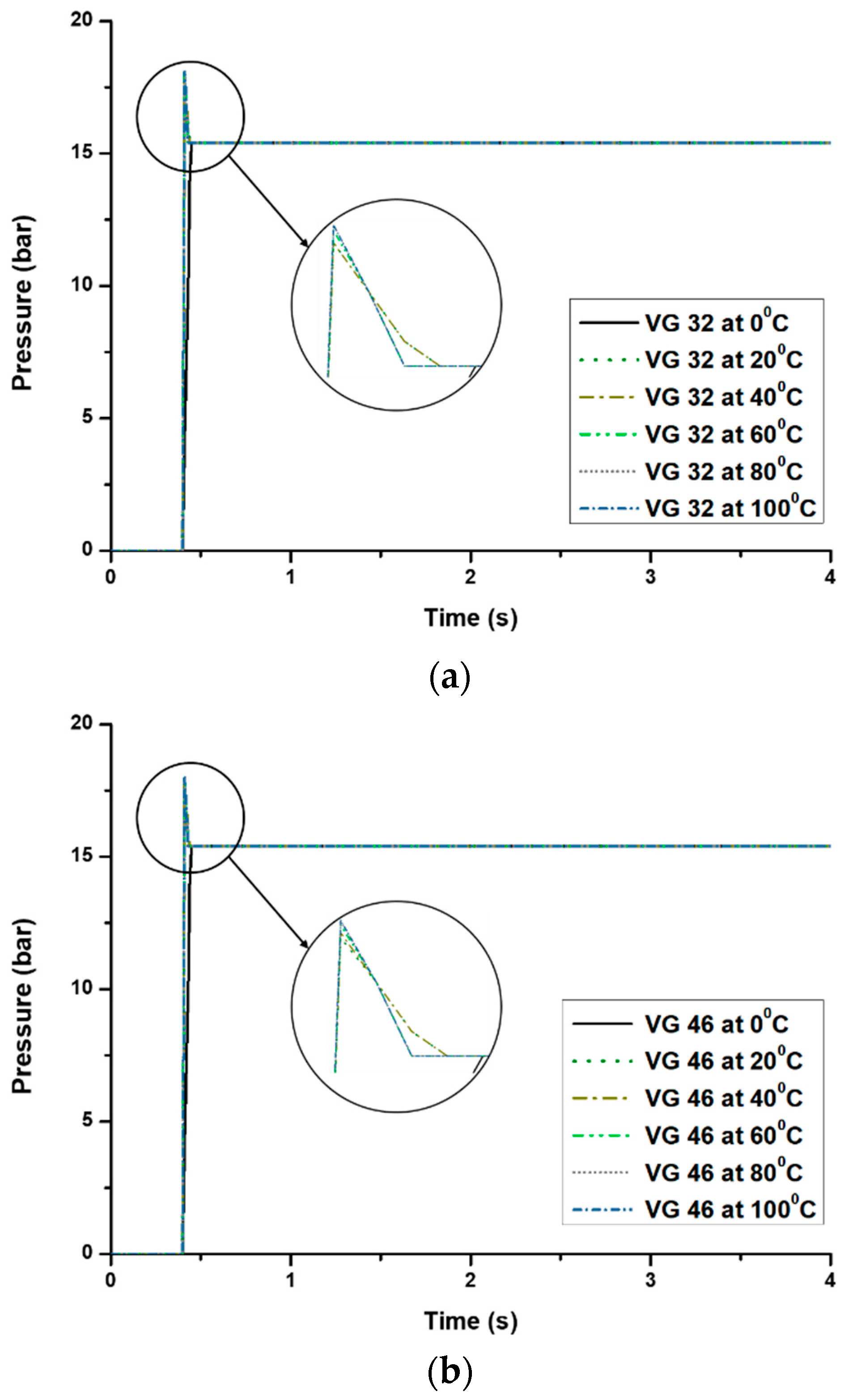
  • It was identified that the maximum pressures of the proportional valve were constant for all conditions, accounting for 15.405 bars.
  • The maximum overshoot was found to be 17.50% at 100 °C for VG 32 and the settling time was 0.45 s at 0 °C for all of the hydraulic oils, which satisfied the boundary conditions.
In summary, as the pressure of the proportional valve is constant and stable, it is guaranteed that this PID control algorithm considering viscosity is able to compensate for the viscous effects of hydraulic oils. After analyzing the response characteristics of the proportional valve statistically, it is also guaranteed that this PID control algorithm can perform with accuracy for the temperature-dependent viscosity of any hydraulic oils. The results indicate that the movement of the actuator would be uninformed, as the proportional valve pressures are constant for all of the conditions of the experiment.
In addition, the rice transplanter has required a faster response for accurately controlling and maintaining a uniform planting depth. The planting depth is highly associated with hydraulic actuator displacement. The results indicate that the rice transplanter is capable to plant the seedlings without tilting. The limitation of this study is that the stability test was conducted by only a simulation performance repeatedly. In the near future, an experimental test bench or field performance will be performed for the validation of the PID control algorithm of the automatic planting depth control system of the rice transplanter. Finally, this control algorithm could be helpful in minimizing the tilting of the planted seedling using a rice transplanter. Ultimately, it would improve the performance and accuracy of the transplanter.

Author Contributions

Conceptualization, M.A.A.S. and Y.-J.K.; methodology, Y.-J.K. and M.A.A.S.; software, M.A.A.S.; validation, M.A.A.S., W.-S.K., T.-J.K., and Y.-S.K.; formal analysis, M.A.A.S., W.-S.K., and T.-J.K.; investigation, Y.-J.K., S.-O.C., C.-H.C., and H.-J.L.; writing (original draft preparation), M.A.A.S.; writing (review and editing), M.A.A.S.; visualization, W.-S.K. and Y.-S.K.; supervision, Y.-J.K.; project administration, Y.-J.K. All authors have read and agreed to the published version of the manuscript.

Funding

Financial supports from Korean Institute of Planning and Evaluation for Technology in Food, Agriculture, Forestry and Fisheries (IPET) through the Advanced Production Technology Development Program, funded by the Ministry of Agriculture, Food, and Rural Affairs (MAFRA) (317014-03). It was also supported by the Korea Institute of Planning and Evaluation for Technology in Food, Agriculture, Forestry (IPET) through the Advanced Production Technology Development Program, funded by the Ministry of Agriculture, Food and Rural Affairs (MAFRA)(318072-03).

Conflicts of Interest

The authors declare no conflict of interest.

References

  1. Goldstein Research. Available online: https://www.goldsteinresearch.com/report/rice-transplanter-market-outlook-2024-global-opportunity-and-demand-analysis-market-forecast-2016-2024 (accessed on 9 January 2020).
  2. Kim, W.S.; Kim, Y.S.; Kim, Y.J.; Choi, C.H.; Inoue, E.; Okayasu, T. Analysis of the load of a transplanter PTO shaft based on the planting distance. J. Fac. Agric. Kyushu Univ. 2018, 63, 97–102. [Google Scholar]
  3. Kim, Y.S.; Lee, P.U.; Kim, W.S.; Kwon, O.W.; Kim, C.W.; Lee, K.H.; Kim, Y.J. Strength analysis of a PTO (Power Take-Off) gear-Train of a multi-Purpose cultivator during a rotary ditching operation. Energies 2019, 12, 1100. [Google Scholar] [CrossRef] [Green Version]
  4. Yu, S.C.; Shin, S.Y.; Kang, C.H.; Kim, B.G.; Kim, J.O. Current status of agricultural mechanization in South Korea. In Proceedings of the 2015 ASABE Annual International Meeting, New Orleans, LA, USA, 26–29 July 2015; ASABE: St. Joseph, MI, USA, 2015. Paper No. 152189653. [Google Scholar]
  5. Sanusan, S.; Polthanee, A.; Audebert, A.; Seripong, S.; Mouret, J.C. Growth and Yield of Rice (Oryza sativa L.) as affected by Cultivars, Seeding Depth and Water Deficits at Vegetative Stage. Asian J. Plant Sci. 2010, 9, 36–43. [Google Scholar] [CrossRef] [Green Version]
  6. Bozorgi, H.R.; Faraji, A.; Danesh, R.K. Effect of plant density on yield and yield components of rice. World Appl. Sci. J. 2011, 12, 2053–2057. [Google Scholar]
  7. Huang, J.; Wang, X.; Wang, H.; Hao, H. Development of a flow control valve with digital flow compensator. Flow Meas. Instrum. 2019, 66, 157–169. [Google Scholar] [CrossRef]
  8. Lisowski, E.; Filo, G.; Rajda, J. Analysis of Flow forces in the initial phase of throttle gap opening in a proportional control valve. Flow Meas. Instrum. 2018, 59, 157–167. [Google Scholar] [CrossRef]
  9. Lisowski, E.; Filo, G.; Rajda, J. Pressure compensation using flow forces in a multi-section proportional directional control valve. Energy Convers. Manag. 2015, 103, 1052–1064. [Google Scholar] [CrossRef]
  10. Jeong, Y.H.; Park, T.J. THD analysis of a hydraulic servo valve using CFD. J. Korean Soc. Fluid Constr. Equip. 2014, 11, 8–13. [Google Scholar]
  11. Zardan, B.; Borghi, M.; Cillo, G.; Rinaldini, C.A.; Mattarelli, E. Design of two-stage On/Off cartridge valves for mobile applications. Energy Procedia 2017, 126, 1123–1130. [Google Scholar] [CrossRef] [Green Version]
  12. Wang, F.; Gu, L.; Chen, Y. A continuously variable hydraulic pressure converter based on high-Speed on–Off valves. Mechatronics 2011, 21, 1298–1308. [Google Scholar] [CrossRef]
  13. Lian, H.; Xiwen, L.; Zuoxi, Z.; Zhigang, Z.; Junwan, H.; Bin, C. Design of electronic control device and control algorithm for rice transplanter. Trans. CSAE 2009, 25, 118–122, (In Chinese, with English abstract). [Google Scholar]
  14. Wei, L.; Zhang, X.; Jia, Q.; Liu, Y. Automatic Navigation System Research for PZ60 Rice Planter. In Computer and Computing Technologies in Agriculture VIII; Li, D., Chen, Y., Eds.; Springer: Cham, Switzerland, 2015; Volume 452, pp. 653–661. [Google Scholar]
  15. Liu, J.Y.; Tan, J.Q.; Mao, E.R.; Song, Z.H.; Zhu, Z.X. Proportional directional valve based automatic steering system for tractors. Front. Inf. Technol. Electron. Eng. 2016, 17, 458–464. [Google Scholar] [CrossRef]
  16. Siddique, M.A.A. Simulation Model of the Automatic Planting Depth Control System for Rice Transplanter Using Proportional Valve. Master’s Thesis, Chungnam National University, Daejeon, Korea, June 2019. [Google Scholar]
  17. Manzone, M. Performance of an electric control system for hydraulically driven forestry tandem trailers. Biosyst. Eng. 2015, 130, 106–110. [Google Scholar] [CrossRef] [Green Version]
  18. Raikwar, S.; Tewari, V.K.; Mukhopadhyay, S.; Verma, C.R.B.; Rao, M.S. Simulation of components of a power shuttle transmission system for an agricultural tractor. Comput. Electron. Agric. 2015, 114, 114–124. [Google Scholar] [CrossRef]
  19. Foster, C.A.; Strosser, R.P.; Peters, J.; Sun, J.Q. Automatic velocity control of a self-Propelled windrower. Comput. Electron. Agric. 2005, 47, 41–58. [Google Scholar] [CrossRef]
  20. Saeys, W.; Engelen, K.; Ramon, H.; Anthonis, J. An automatic depth control system for shallow manure injection, Part 1: Modelling of the depth control system. Biosyst. Eng. 2007, 98, 146–154. [Google Scholar] [CrossRef]
  21. Saeys, W.; Deblander, J.; Ramon, H.; Anthonis, J. High-Performance flow control for site-Specific application of liquid manure. Biosyst. Eng. 2008, 99, 22–34. [Google Scholar] [CrossRef]
  22. Siddique, M.A.A.; Kim, W.S.; Beak, S.Y.; Kim, Y.J.; Choi, C.H. Simulation of hydraulic system of the rice transplanter with AMESim software. In Proceedings of the 2018 ASABE Annual International Meeting, Detroit, MI, USA, 29 July–1 August 2018; ASABE: St. Joseph, MI, USA, 2018. Paper No. 201800981. [Google Scholar]
  23. Anderson, W.R. Controlling Electrohydraulic Systems, 1st ed.; Marcel dekker: New York, NY, USA, 1988. [Google Scholar]
  24. Zhang, Q. Hydraulic linear actuator velocity control using a feedforward-plus-PID control. Int. J. Flex. Autom. Integr. Manuf. 1999, 7, 277–292. [Google Scholar]
  25. Feng, B.; Gong, G.; Yang, H. Self-Tuning parameter fuzzy PID temperature control in a large hydraulic system. In Proceedings of the 2009 IEEE/ASME International Conference on Advanced Intelligent Mechatronics, Singapore, 14–17 July 2009. [Google Scholar]
  26. Lui, Z.; Hu, X.; Li, X. Study on fuel oil temperature PID control system and simulation. In Proceedings of the 2012 2nd International Conference on Consumer Electronics, Communications and Networks (CECNet), Yichang, China, 21–23 April 2012. [Google Scholar]
  27. Chen, Z.; Wang, W. Analysis of temperature characteristics of electrohydraulic servo valve based on AMESim. In Proceedings of the International Conference of Mechanical, Electrical, Electronic Engineering & Science (MEEES 2018), Chongqing, China, 26–27 May 2018. [Google Scholar]
  28. Javalagi, S.; Singireddy, S.R. Hydraulic Fluid Properties and Its Influence on System Performance. Master’s Thesis, Linköping University, Linköping, Sweden, 2012. [Google Scholar]
  29. Huang, H.; Zhang, S.; Yang, Z.; Tian, Y.; Zhao, X.; Yuan, Z.; Hao, S.; Leng, J.; Wei, Y. Modified smith fuzzy PID temperature control in oil-Replenishing device for deep-sea hydraulic system. Ocean Eng. 2018, 149, 14–22. [Google Scholar] [CrossRef]
  30. Mahmood, Q.A.; Nawaf, A.T.; Esmael, M.N.; Abdulateef, L.T.; Dahham, O.S. PID temperature control of demineralized water tank. IOP Conf. Ser. Mater. Sci. Eng. 2018, 454, 1–10. [Google Scholar] [CrossRef]
  31. Han, C.; Hwang, Y.H.; Choi, S.B. Tracking control of a spool displacement in a direct piezoactuator driven servo valve system. Front. Mater. 2017, 4, 1–9. [Google Scholar] [CrossRef] [Green Version]
  32. Abdelaziz, H.O.; Ahmed, M.M.; Mahmoud, D. Effect of viscous friction coefficients variation on robot’s joint PID control. Int. J. Eng. Manag. Humanit. Soc. Sci. Paradig. (IJEMHS) 2016, 21, 11–14. [Google Scholar]
  33. Heo, Y.J.; Kang, J.; Kim, M.J.; Chung, W.K. Tuning free controller to accurately regulate flow rates in a microfluidic network. Sci. Rep. 2016, 6, 23273. [Google Scholar] [CrossRef] [PubMed]
  34. Nam, D.N.C.; Tri, N.M.; Park, H.G.; Ahn, K.K. Position control of electro hydraulic actuator (EHA) using an iterative learning control. J. Korean Soc. Fluid Constr. Equip. 2014, 11, 1–7. [Google Scholar]
  35. Bravo, W.A.; Canuto, E.; Agostani, M.; Bonadei, M. Proportional electrohydraulic valves: An embedded model control solution. Control Eng. Pract. 2017, 62, 22–35. [Google Scholar] [CrossRef]
  36. Ogata, K. Modern Control Engineering, 4th ed.; Prentice-Hall, Inc.: Upper Saddle River, NJ, USA, 2002; pp. 681–751. [Google Scholar]
  37. Anthonis, J.; Mouazen, A.M.; Saeys, W.; Ramon, H. An Automatic Depth Control System for Online Measurement of Spatial Variation in Soil Compaction, Part 3: Design of Depth Control System. Biosyst. Eng. 2004, 89, 59–67. [Google Scholar] [CrossRef]
  38. Condon, S.F.; Ward, S.M.; Holden, N.M.; McGee, A. The Development of a Depth Control System for a Peat Milling Machine, Part I: Sensor Development. J. Agric. Eng. Res. 2001, 80, 127–137. [Google Scholar] [CrossRef]
  39. Lee, J.; Yamazaki, M.; Oida, A.; Nakashima, H.; Shimizu, H. Electro-Hydraulic tillage depth control system for rotary implements mounted on agricultural tractor Design and response experiments of control system. J. Terramechanics 1998, 35, 229–238. [Google Scholar] [CrossRef]
  40. Søgaard, H.T. Automatic Control of a Finger Weeder with Respect to the Harrowing Intensity at Varying Soil Structures. J. Agric. Eng. Res. 1998, 70, 157–163. [Google Scholar] [CrossRef]
  41. Weatherly, E.T.; Bowers, C.G. Automatic depth control of a seed planter based on soil drying front sensing. Trans. ASAE 1997, 40, 295–305. [Google Scholar] [CrossRef]
  42. Siddique, M.A.A.; Kim, W.S.; Baek, S.Y.; Kim, Y.S.; Choi, C.H.; Kim, Y.J.; Park, J.K. Determination of PID coefficients for the ascending and descending system using proportional valve of a rice transplanter. J. Biosyst. Eng. 2018, 43, 331–341. [Google Scholar]
  43. Busquets, E.; Ivantysynova, M. Temperature prediction of displacement controlled multi-Actuator machines. Int. J. Fluid Power 2013, 14, 25–36. [Google Scholar] [CrossRef]
  44. Park, Y.N.; Kim, D.C.; Park, S.J. Delayed operation characteristics of power shuttle according to hydraulic oil temperature in the hydraulic circuit of agricultural tractor. J. Biosyst. Eng. 2015, 40, 95–101. [Google Scholar] [CrossRef] [Green Version]
  45. Wallman, N.; Lindblad, K. Single Acting Hydraulic Cylinder; Wallmek I Kungälv AB: Kungalv, Sweden, 2017; No. US20170102013A1. [Google Scholar]
  46. Amirante, R.; Lippolis, A.; Tamburrano, P. Theoretical and experimental analysis of a coupled system proportional control valve and hydraulic cylinder. Univ. J. Eng. Sci. 2013, 1, 45–56. [Google Scholar]
  47. Kim, Y.J.; Chung, S.O.; Lee, D.H.; Choi, C.H.; Kim, W.S. Automatic clutch control for automated transmission of agricultural tractor. In Proceedings of the 8th International Symposium on Machinery and Mechatronics for Agriculture and Biosystems Engineering (ISMAB), Niigata, Japan, 23–25 May 2016. [Google Scholar]
  48. Jantzen, J.; Jakobsen, C. Tuning PID controller tuning into a simple consideration of settling time. In Proceedings of the 2016 European Control Conference (ECC), Aalborg, Denmark, 29 June–1 July 2016. [Google Scholar] [CrossRef]
  49. He, X.; Cui, T.; Zhang, D.; Wei, J.; Wang, M.; Yu, Y.; Liu, Q.; Yan, B.; Zhao, D.; Yang, L. Development of an electric-Drive control system for a precision planter on a closed-Loop PID algorithm. Comput. Electron. Agric. 2017, 136, 184–192. [Google Scholar] [CrossRef]
  50. Gapinski, R.E. All-Weather Tractor Hydraulic Fluid Using a Mixture of Viscosity Modifier Types to Meet Shear-Stable Ultigrade Viscosity Requirements. U.S. Patent No. US7189682 B2, 13 March 2007. [Google Scholar]
  51. Krisnangkura, K.; Yimsuwan, T.; Pairintra, R. Am empirical approach in predicting biodiesel viscosity at various temperatures. Fuel 2006, 85, 107–113. [Google Scholar] [CrossRef]
  52. Esteban, B.; Riba, J.R.; Baquero, G.; Rius, A.; Puig, R. Temperature dependence of density and viscosity of vegetable oils. Biomass Bioenergy 2012, 42, 164–171. [Google Scholar] [CrossRef] [Green Version]
  53. Wang, N.; Wang, J.; Li, Z.; Tang, X.; Hou, D. Fractional-Order PID control strategy on hydraulic-Loading system of typical electromechanical platform. Sensors 2018, 18, 3024. [Google Scholar] [CrossRef] [Green Version]
  54. Toscano, R. A simple robust PI/PID controller design via numerical optimization approach. J. Process Control 2005, 15, 81–88. [Google Scholar] [CrossRef]
  55. Yang, G.; Yao, J.; Le, G.; Ma, D. Adaptive integral robust control of hydraulic systems with asymptotic tracking. Mechatronics 2016, 40, 78–86. [Google Scholar] [CrossRef]
  56. Chen, C.P.; Chiang, M.H. Development of proportional pressure control valve for hydraulic bracking actuator of automobile ABS. Appl. Sci. 2018, 8, 639. [Google Scholar] [CrossRef] [Green Version]
Figure 1. Rice planting machine and its hydraulic system.
Agriculture 10 00073 g001
Figure 2. Hydraulic circuit and PID (proportional-integral-derivative) control algorithm of the planting depth control system of a rice transplanter.
Agriculture 10 00073 g002
Figure 3. PID control algorithm for pressure control without considering viscosity [42].
Agriculture 10 00073 g003
Figure 4. PID control algorithm for position control.
Agriculture 10 00073 g004
Figure 5. Unit step response at various damping ratios for the PID control algorithm.
Agriculture 10 00073 g005
Figure 6. The boundary conditions of the control algorithms considering and without considering viscosity.
Agriculture 10 00073 g006
Figure 7. The viscosity of the hydraulic oils at various temperatures.
Agriculture 10 00073 g007
Figure 8. The responses of the PID control algorithm.
Agriculture 10 00073 g008
Figure 9. Performance of the control algorithm without considering viscosity at various temperatures, namely: (a) hydraulic oils VG 32, (b) VG 46, and (c) VG 68.
Agriculture 10 00073 g009
Figure 10. Performance of the control algorithm considering viscosity at various temperatures, namely: (a) Hydraulic oils VG 32, (b) VG 46, and (c) VG 68.
Agriculture 10 00073 g010aAgriculture 10 00073 g010b
Table 1. Specifications of the selected hydraulic oils.
ItemsParameters
VG 32VG 46VG 68
Brand (model)Kixx (RD HD)
Density kg/L at 15 °C0.8550.8600.866
Kinematic viscosity (mm2/s) at 40 °C3246.267.4
Kinematic viscosity (mm2/s) at 100 °C114112109
Viscosity index114112109
Pour point (°C)−39−36−27
Flash point (°C)221232235
Table 2. The response of the PID coefficients considering viscosity.
Control AlgorithmMax. Overshoot (%)Settling Time 1 (s)Steady-State Error (%)
(Kp = 15, Ti = 10.75, and Td = 0.43)19.900.900
1 The settling time was set within the range of 5% of the final value.
Table 3. The comparison of the proportional valve pressure at different temperatures for the PID control algorithm without considering viscosity.
Hydraulic OilsTemperature (°C)ParametersPressure (bar)
VG 320Max.15.97
Avg. ± Std. Dev.15.15 ± 2.14 a
20Max.15.86
Avg. ± Std. Dev.15.07 ± 2.15 a
40Max.15.47
Avg. ± Std. Dev.14.67 ± 2.34 b
60Max.15.44
Avg. ± Std. Dev.14.50 ± 2.44 b
80Max.15.43
Avg. ± Std. Dev.14.48 ± 2.45 b
100Max.15.43
Avg. ± Std. Dev.14.47 ± 2.45 b
VG 460Max.16.06
Avg. ± Std. Dev.15.22 ± 2.13 a
20Max.16.02
Avg. ± Std. Dev.15.18 ± 2.13 a
40Max.15.54
Avg. ± Std. Dev.14.81 ± 2.26 b
60Max.15.45
Avg. ± Std. Dev.14.55 ± 2.41 c
80Max.15.44
Avg. ± Std. Dev.14.49 ± 2.45 c
100Max.15.43
Avg. ± Std. Dev.14.48 ± 2.45 c
VG 680Max.15.95
Avg. ± Std. Dev.15.11 ± 2.11 a
20Max.15.94
Avg. ± Std. Dev.15.11 ± 2.12 a
40Max.15.48
Avg. ± Std. Dev.14.76 ± 2.25 b
60Max.15.42
Avg. ± Std. Dev.14.52 ± 2.41 c
80Max.15.44
Avg. ± Std. Dev.14.49 ± 2.45 c
100Max.15.43
Avg. ± Std. Dev.14.48 ± 2.45 c
a,b,c Means within each column with the same lettering are not significantly different at p < 0.05 according to Duncan’s multiple range test.
Table 4. Comparison of the response characteristics of the PID control algorithms.
ParametersTemp.
(°C)
PID Control Algorithm
Without Considering ViscosityConsidering Viscosity
VG 32VG 46VG 68VG 32VG 46VG 68
Max. overshoot.
(%) ≤ 25%
0000000
2000015.3015.2914.70
4000015.3015.2915.29
6000016.8416.2615.87
803.853.853.8517.4716.7116.40
1003.483.483.4817.5016.8416.72
Avg. ± Std. Dev.1.22 ± 1.891.22 ± 1.891.22 ± 1.8913.73 ± 6.8013.40 ± 6.6013.16 ± 6.49
Settling time.
(s) ≤ 0.5 s
04.04.04.00.450.450.45
204.04.04.00.420.420.42
402.702.702.700.430.430.43
602.702.702.700.420.420.42
802.702.702.700.420.420.42
1002.702.702.700.420.420.42
Avg. ± Std. Dev.3.13 ± 0.673.13 ± 0.673.13 ± 0.670.43 ± 0.010.43 ± 0.010.43 ± 0.01
Steady state error.
(%) ≤ 1%
0111000
200.940.950.97000
40000000
60000000
80000000
100000000
Avg. ± Std. Dev.0.32 ± 0.500.32 ± 0.500.32 ± 0.50000

