Article

Cooperative Heterogeneous Robots for Autonomous Insects Trap Monitoring System in a Precision Agriculture Scenario

1
Research Centre in Digitalization and Intelligent Robotics (CeDRI), Instituto Politécnico de Bragança, Campus de Santa Apolónia, 5300-253 Bragança, Portugal
2
Laboratório Associado para a Sustentabilidade e Tecnologia em Regiões de Montanha (SusTEC), Instituto Politécnico de Bragança, Campus de Santa Apolónia, 5300-253 Bragança, Portugal
3
Engineering Department, School of Sciences and Technology, Universidade de Trás-os-Montes e Alto Douro (UTAD), 5000-801 Vila Real, Portugal
4
Coordenação do Curso de Engenharia de Software, COENS, Universidade Tecnológica Federal do Paraná—UTFPR, Dois Vizinhos 85660-000, Brazil
5
Applied Robotics and Computation Laboratory—LaRCA, Federal Institute of Paraná, Pinhais 3100, Brazil
6
INESC Technology and Science, 4200-465 Porto, Portugal
7
Department of Electronics Engineering, Federal Center of Technological Education of Celso Suckow da Fonseca (CEFET/RJ), Rio de Janeiro 20271-204, Brazil
*
Author to whom correspondence should be addressed.
Agriculture 2023, 13(2), 239; https://doi.org/10.3390/agriculture13020239
Submission received: 15 December 2022 / Revised: 9 January 2023 / Accepted: 14 January 2023 / Published: 19 January 2023
(This article belongs to the Special Issue Application of Robots and Automation Technology in Agriculture)

Abstract

:
The recent advances in precision agriculture are due to the emergence of modern robotics systems. For instance, unmanned aerial systems (UASs) give new possibilities that advance the solution of existing problems in this area in many different aspects. The reason is due to these platforms’ ability to perform activities at varying levels of complexity. Therefore, this research presents a multiple-cooperative robot solution for UAS and unmanned ground vehicle (UGV) systems for their joint inspection of olive grove inspect traps. This work evaluated the UAS and UGV vision-based navigation based on a yellow fly trap fixed in the trees to provide visual position data using the You Only Look Once (YOLO) algorithms. The experimental setup evaluated the fuzzy control algorithm applied to the UAS to make it reach the trap efficiently. Experimental tests were conducted in a realistic simulation environment using a robot operating system (ROS) and CoppeliaSim platforms to verify the methodology’s performance, and all tests considered specific real-world environmental conditions. A search and landing algorithm based on augmented reality tag (AR-Tag) visual processing was evaluated to allow for the return and landing of the UAS to the UGV base. The outcomes obtained in this work demonstrate the robustness and feasibility of the multiple-cooperative robot architecture for UGVs and UASs applied in the olive inspection scenario.

1. Introduction

Precision agriculture is a concept based on monitoring, measurement, and decision-making strategies to optimize the decision support for farm management [1]. Due to recent advances in sensors [2], communication [3], and information processing technologies [4], automated robotic systems are playing an essential role in agricultural environments for sensing [5], inspection [6], pest control [7], and harvesting [8], among others. An interesting review regarding the application of sensors and actuators in agricultural robots can be found in the study by Xie et al. [2].
These automated solutions give new opportunities due to the possibility of efficiently performing manual tasks, saving labor costs, and preventing risks in human operations [1]. In the last few years, intelligent and adaptable solutions have been the focus in order to increase the automaticity level of these robots in large areas [9], especially in agricultural farming applications, where they may reduce production costs, achieving operational efficiency. The technological advances to reach this autonomy level are covered by computer methods for control and navigation strategies [10,11,12] and robust sensing approaches [13].
For instance, applying an Unmanned Aerial System (UAS) in precision agriculture operations allows for the real-time management decisions of the farms. An interesting application of UASs is conducting them to monitor insects that directly affect crops, such as in [14,15]. Regarding olive groves and grapevines, the recurrent practices rely on the visual inspection of these plantation cultures during a few months or deploying traps at their base during the spring and summer months [16]. The major issues with these methods are the intensive labor and time spent every two or four weeks [17]. In this sense, this work proposes using a multiple cooperative robots approach by applying UAS and Unmanned Ground Vehicle (UGV) systems to automate the inspection of olive groves insect traps. Note that multiple cooperative robots are a prominent solution to be incorporated into the broad-acre land of agricultural farms, bringing new perspectives and effectiveness to the production and monitoring processes [18,19].
Several multi-robot solutions only use homogeneous systems; that is, cooperation only among UASs or only among UGVs [20,21]. Although this approach’s implementation simplicity and scalability among homogeneous robots favor the missions to be performed, the heterogeneity of robots allows the robot team to improve the tasks in different aspects and levels to offer redundancy [21]. As multiple cooperation among heterogeneous robots is a new disruptive technology, it incorporates challenges to partition the tasks by taking into account the robot characteristics, such as the battery time and covering area [21], and innovative applications and concepts [22]. Note that UGVs can carry a large payload, bringing the possibility of attaching different sensors and actuators to them. A drawback that UGVs encounter is their low point of view. On the contrary, the UAS presents a high point of view but low payload capacity and limited flight time due to its power efficiency [22].
In the literature, many reports surveyed the heterogeneous robots cooperation strategies [23,24]. Among these strategies, the UAS landing on a UGV during missions is an interesting interaction between heterogeneous robots. This can also be referred to as a rendezvous. This physical cooperation occurs when the UGV is moving, and the UAS needs to adjust its velocity dynamically to reach the landing spot [22]. This landing procedure can be performed using a vision-based procedure [25] or sensor fusion [26], and it involves a controller strategy and trajectory-planning technique [23].

Main Contributions

This research intends to propose multiple cooperative robot architecture (UAS and UGV systems) to automate the inspection of olive grove insect traps. The UGV will move among the aisles of olive groves carrying the UAS in its roof, searching for a trap fixed on a tree. When the UGV vision algorithm identifies the trap, the autonomous UAS will take off, inspect some olives to collect information on insects in the traps, and then return and land on the UGV. This research proposes a UAS vision-based landing onto a UGV system approach that considers the dynamics of both AGV and UAS robots and the environmental conditions. The main objective of this work is to propose a new cooperative autonomous robotic technique to achieve images of the insect traps used to increase the infestation data collection quality and velocity, allowing for the creation of better plague control policies and strategies applied to olive grove cultures and similar ones. The main contributions can be summarized as follows:
  • Implementation of an artificial-neural-network-based algorithm to identify the chromotropic yellow traps fixed in a group of trees and provide position and orientation data to the UGV and UAS navigation algorithms to execute their missions.
  • Evaluation of the proposed architecture operation in a simulated environment using small-sized vehicles integrated through ROS as a first step to build a fully operational autonomous cooperative trap capture system.
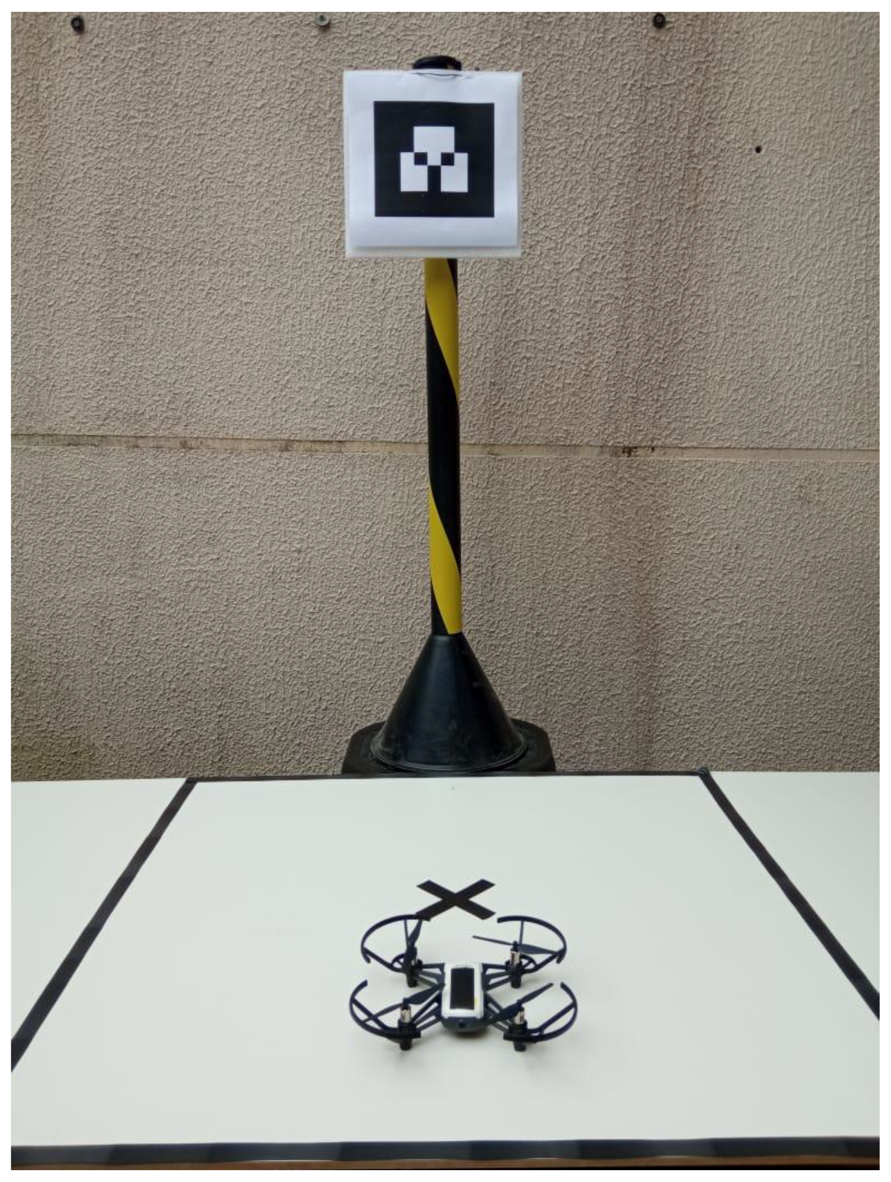
  • Proposition and experimental evaluation control strategy combined with a fiducial marker for UAS vision-based landing onto a UGV roof considering the specific application environment and operational conditions.
This investigation step focuses on executing a first evaluation of the UAS and UGV vision-based navigation and control algorithms, considering the specific environmental conditions. A UAS search and landing algorithm at the UGV roof, based on a fiducial marker and vision-based processing, was also evaluated. Evaluating this mechanism is essential for providing a proof-of-concept to the autonomous cooperative UAS-UGV trap image capture solution, allowing for a future improvement in the techniques based on the enhanced capability hardware and mechanical platform.

2. Background and Related Works

2.1. Agricultural Robots

The report given by the Food and Agriculture Organization (FAO) of the United Nations (UN) expects, in the year 2050, an increase in the world population to approximately 10 billion [27]. This is a piece of evidence regarding the necessity of more agricultural production. Thus, currently, most of the broad-acre land farms have automated operations and automatic types of machinery, which are derived from the necessity of improving the quality of the food and the production [28,29].
Unmanned robots are becoming frequent in daily life activities, and they have been applied in a wide range of fields [10,30,31]. For instance, UASs have been used for crop field monitoring [32], civil structures inspection and analysis [9], and surveillance [33], among others. Regarding mobile robots, they cover applications such as cleaning [34], surveillance [35], support for crop monitoring [36], assisting people with disabilities [37], etc. Several reviews about the application of UAS and UGVs exist in the literature. For instance, Kulbacki et al. [38] surveyed the application of UASs for planting-to-harvest tasks. In the work of Manfreda et al. [39], the authors reviewed the application of UASs for environmental monitoring. Regarding the sensory system, the work of Maes et al. [40] presents interesting perspectives for remote sensing with UASs. For UGV systems, Hajjaj et al. [41] addressed challenges and perspectives on using UGVs in precision agriculture.
An overview of the cooperation of multi-robots (i.e., robot and human, UGV teams, UAS teams, and UGV-UAS teams) in agriculture can be found in Lytridis et al. [42]. In accordance with this review, the application of a cooperative robot team for farming tasks is not very widespread yet, such as the application of individual agricultural robot developed for specific tasks. Regarding heterogeneous robots, despite offering significant advantages for exploration, different aspects must be addressed due to the inherent limitations of each type of robot used [22]. For instance, in the work of Shi et al. [21], the authors addressed the problem of the synchronization of tasks among these heterogeneous robots using an environment partitioning approach, taking into account the heterogeneity cost space. Kim et al. [43] developed an optimal path strategy for 3D terrain maps based on UAS and UGV sensors. This strategy enabled the guidance of the robots to perform their tasks.
Considering the interaction, which is close to the intention of this work’s cooperative architecture, in Navaez et al. [22], the authors proposed an autonomous system for docking a vertical take-off and landing (VTOL) with a mobile robot with a robot manipulator mounted on it. This robot has a visual sensor that uses this information to execute stable VTOL tracking to achieve contact firmly. The authors of Maini and Sujit [44] developed a coordination approach between a refueling UGV and a quad-rotor UAS for large-area exploration. Arbanas et al. [45] designed a UAS to pick up and place parcels into a mobile robot for autonomous transportation.
As can be seen, different aspects of the collaboration between heterogeneous robots still need to be addressed, especially in the agriculture field. Aspects such as the control strategy for a UAS landing or taking off from a mobile robot to a determined area for exploration or inspection (such as the case in this research), and synchronization approaches for exploration and navigation are the key points explored in this work.

2.2. UAS Landing Strategies

A particular point of UAS applications is the limited energy source of these aircraft. For instance, using a UGV as a recharging base is a practical solution to this limitation but demands that the UAS search and land in the UGV autonomously. The UAS landing strategy depends on the type of landing zone: indoor or outdoor. The indoor landing zone is a static and flat zone. Contrarily, the outdoor landing can be performed in static or dynamic zones. In both indoor and outdoor zones, the landing can be known (i.e., marked surfaces) or unknown (i.e., free of marks) [46]. Note that, in an outdoor environment, this procedure can be more challenging due to the possibility of the UAS landing suffering from factors such as airflow, obstacles, and irregularities in the ground landing surface, among others [47].
The present work focuses on the control approach for outdoor autonomous visual-based landing on a moving platform. A fiducial marker mounted on the top of the mobile robot was used as a visual reference to assist the UAS landing. As presented in the survey of Jin et al. [47], a few fiducial markers were used for this UAS landing procedure, such as point, circles, H-shaped, and square-based fiducial markers. Through computer vision algorithms that perform color extraction, recognize specific blobs and geometry, and connect points, it is possible to estimate the UAS relative position and orientation concerning the landing platform.
Despite the several improvements in and works on the area of fiducial marker and landing algorithms to assist the UAS [48,49,50,51,52,53,54], some challenges still need to be addressed for the visual servoing controller. For instance, the authors of Acuna and Willet [55] dealt with the limit distance issue to detect the fiducial marker by proposing a control scheme to dynamically change the appearance of the marker to increase the range of detection. However, they do not address the landing algorithm. Khazetdinov et al. [48] developed a new type of fiducial marker called embedded ArUco (e-ArUco). The authors performed the tests with the developed marker and the landing algorithm within the Gazebo simulator using the ROS framework. As in the previous cited work, the authors focused on the developed fiducial marker.
It is possible to observe that the landing procedure onto a moving AGV has several issues that need to be addressed, especially considering the particularities of the proposed application. The irregular terrain, the small aperture between the trees, and the presence of variate obstacles, illumination, and shadowing of the visual markers, among others, bring challenges to the proposition of a fully autonomous landing strategy. In the present work, a simplistic solution is proposed, using fiducial markers placed at the roof of the UGV in a vertical position. In addition, specific conditions were kept to the proper operation of this schema.

3. Proposed Methodology

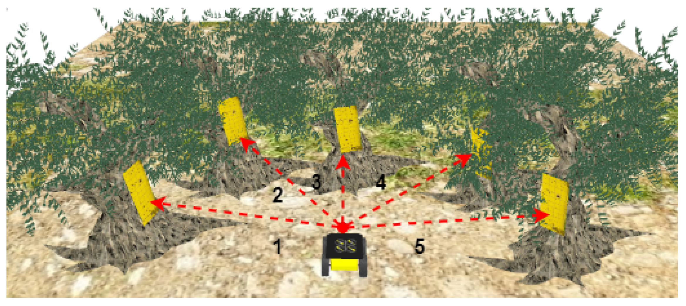
3.1. Problem Definition

The Bactrocera oleae fly species is the major pest of olives [56,57]. The female fly put the eggs in the fruit, causing economic breaks in the culture. It is essential to control this kind of infestation, but it is also essential to provide a sustainable process to achieve this control, avoiding the extensive use of pesticides. One possible solution for collecting the fly infestation data and performing intelligent management is using traps covered with food and sexual attractants fixed on the tops of the olive trees. This trap is kept for days or weeks and manually collected and inspected by human specialists. This inspection includes differentiating the olive fly from other species that do not attack the olive fruit and counting the number of female flies captured by the trap, which is a slow and demanding task.
Inspections carried out by human specialists, who manually identify the incidence of insects on yellow chromotropic traps in olive groves or similar, are commonly applied today, requiring the displacement on foot of one or more specialists along the olive grove cultivation regions. However, the method in question could be more laborious and slow. It normally occurs at a given weekly frequency, which is a potential problem concerning decision making given that insect infestations on olives can occur very quickly.
In the traditional method, the evaluation of the incidence of insects in yellow chromotropic traps usually occurs weekly or fortnightly, requiring the action of technicians to quantify the male and female insects trapped in the traps. This process typically occurs in April through October, when the cycle of the infestation of the main pests in olive groves occurs [58]. In this sense, adopting autonomous systems, whose application automates the inspection process of traps in olive groves, is an excellent solution for mitigating the financial losses caused by attacks by regional pests [59,60,61,62].
The use of cooperative robotic systems to automate this task, i.e., to check the incidence of pests in traps during olive grove cultivation, is an exciting approach with enormous potential for reducing human effort in this type of activity. It makes it possible to reduce the inspection time on the traps, increase the priority of pest incidence analysis, acquire a larger volume of data, and assist in making strategic decisions to combat pests. The yellow chromotropic traps used in olive groves are randomly distributed throughout the growing region, and usually only one trap is added per chosen tree. The positioning traps are located in an area that is easily accessible to the human operator, usually at eye level, to facilitate the analysis of insect incidence [63].
The proposed architecture allows for capturing images of the traps at short intervals, such as daily, which increases the collection of infestation data and allows for a faster performance of control actions compared to the traditional method. The proposed method requires that the trap be fixed on the outer face of the top, without covering the leaves of the olive groves and with good visibility, allowing for an adequate image capture with the use of the drone. Figure 1 illustrates the positioning normally used to adjust the traps on the crowns of olive groves, this being in an area of easy visibility and without many obstructions caused by leaves or branches.
Therefore, this work creates a set of algorithms to adequately capture trap images using a small UAS with vision-based control algorithms. To achieve this goal, the UAS identifies and reaches a pre-defined position in front of the trap, captures images of it, and returns to the UGV to land on the vehicle’s roof, heading to the next inspection point. The evaluation of capture parameters (illumination, shading, distance, camera resolution) and the results of image processing algorithms ysed to perform insect counting and classification are outside the scope of this work. Future work will investigate the parameters of image capture conditions to allow for the automatic counting and classification of insects using artificial intelligence algorithms.

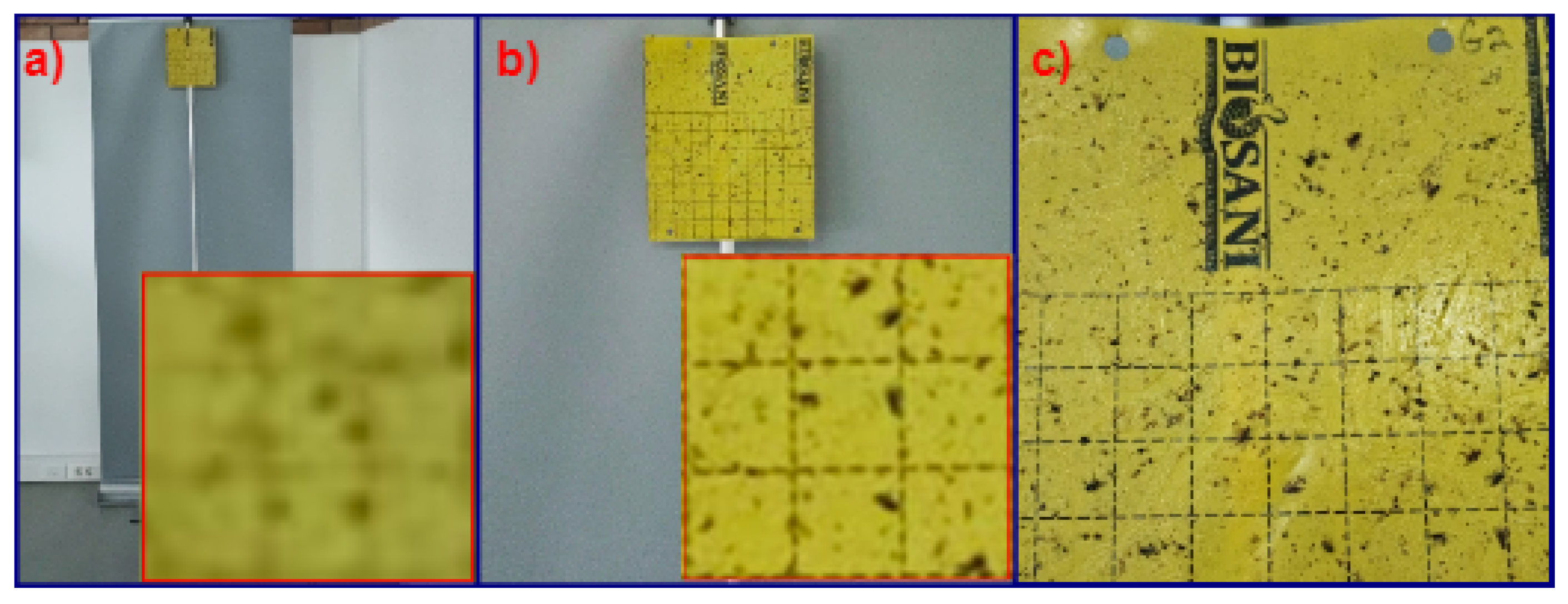
3.2. Image Capture Parameters Definition

To define the distances at which the UAS can identify the insects in the yellow chromotropic traps, parameters such as camera resolution, lighting conditions, and distances between the camera and the target must be evaluated. In this sense, some tests were carried out with a smartphone’s camera with full HD resolution to estimate the minimum distance necessary for a UAS to identify insects in yellow chromotropic traps. For this, the following methodology was adopted:
  • In this experiment, a yellow chromotropic trap was positioned at a height of approximately 1.70 cm, with insects (Bactrocera Olea) trapped on it.
  • A measuring tape was used to guide the distance between the camera (from a smartphone) and the trap.
  • For every 30 cm distance between the camera and the trap, five images were captured. The process occurred until reaching the maximum distance corresponding to 5 m.
  • The test took place in a controlled environment with exposure to diffused sunlight.
The digital camera used in the experiment has a 108 MP, f/1.8, 26 mm (wide), 1/1.52″, 0.7 µm, PDAF full HD resolution, and autofocus. This camera was chosen instead of the Tello Drone camera used in the landing experiments because it provides a better image quality capture, which is essential to the proof of concept. Figure 2 illustrates part of the results obtained by the methodology in question.
In this test environment, it was observed that capturing without optical zoom at long distances will not provide an acceptable image quality for post-processing algorithms. This is a future challenge for this proposal, considering that the UAS in a real environment must only operate close to the tree or other existing obstacles in the inspection scenario. This demand must be faced with adequate image capture hardware with an optical zoom capability, whose resolution allows for the correct classification of flies using artificial intelligence algorithms. In the present work, the researchers set the maximum detection distance at 5 m for the UAS. This distance was established considering UAS security issues and because they are linked to the standard camera settings used in the CoppeliaSim simulator. When implemented, the fully functional version of the system must use a camera with an optical zoom capable of capturing adequate images for the IA processing algorithms at a 5.0 m distance once this is set as the operational distance capture for the UAS. The definition of this camera depends on careful experimentation considering real-world environmental conditions.

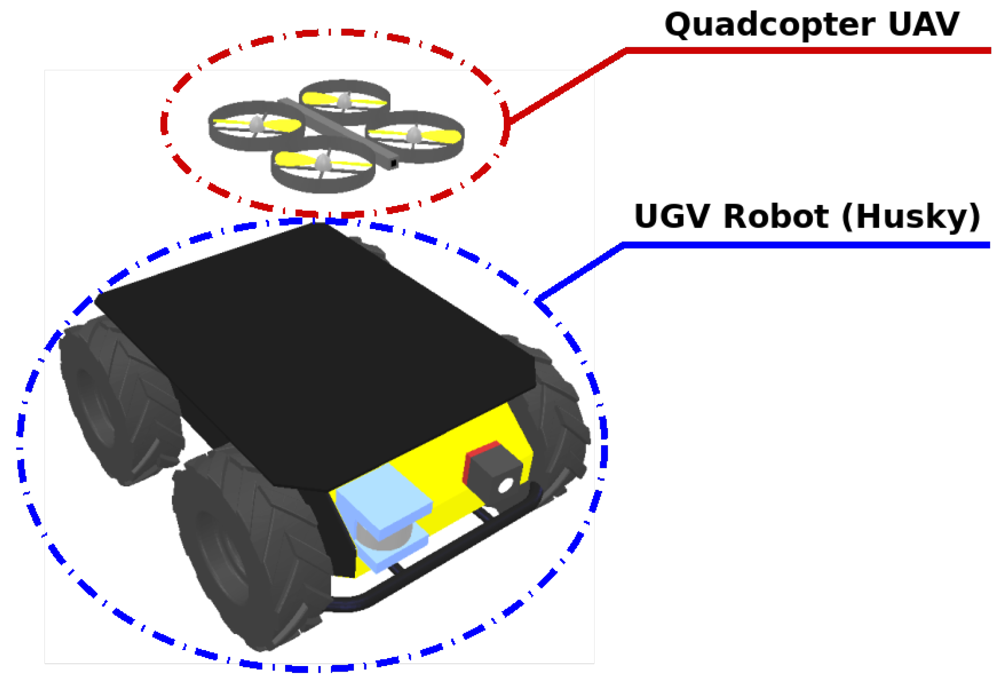
3.3. Overview of the Robotic Architecture Strategy

Figure 3 presents a global overview of the proposed strategy. It is possible to observe in this figure that the UGV moves between the aisles of the olive groves, from one waypoint to another (blue rectangle), using regular GPS data. The mission corresponds to leading the UGV to inspect the olives and find the nearest insect trap in a tree row. The UGV continues to move slowly, with the UAS positioned over the UGV, while the vision algorithm reaches for a trap in the trees. When the UGV identifies a trap, it stops, and the UAS takes off to start an image capture mission, using the trap position to move to a proper place and alignment and capturing a preset number of images of this trap. After finishing the captures, the UAS rotates to search for the reference landing AR-Tag fixed in the UGV and starts moving to it, landing on the vehicle’s roof after achieving the proper landing coordinates.
When the landing operation step is over, the UAS sends an end-of-operation status message to the UGV, the vehicle starts a new movement to search for the next trap, and the operation restarts. The UGV will execute this behavior in an entire tree row, using the GPS data to feed the navigation algorithm. At this point of the research, the objective is to evaluate the trap identification algorithm, the UAS autonomous search, and moving control using the YOLO to provide the position data and the UAS return in the simulated environment, and the base and landing algorithm in real-world conditions. Note that the YOLOv7 was used due to its ease of training, speed in detection, and versatility [10]. In addition, this algorithm only uses convolutional layers, which makes the convolutional neural network (CNN) invariant to the resolution and size of the image [64].
The project and evaluation of the mobile UGV base, obstacle sensing, intelligent navigation, and other necessary solutions for properly operating this architecture will be investigated in future work. In addition, the collision avoidance sensing used to provide secure navigation to the UAS is not covered in this research step due to the payload limit of the small-sized aircraft used to evaluate the visual control algorithm. As the UAS has limited flight time due to battery limitations, the primary intention of the heterogeneous collaboration is to allow the aerial system to land at the top of the UGV and save power during the navigation between two traps. Figure 4 presents the flowchart that describes the actions taken by the UAS-UGV system addressed in this research.
The experiments described in this work aim to create a first proof-of-concept of the cooperative UAS-UGV architecture to capture the insect traps images in a proper condition to be post-processed by the AI algorithms. The focus of the experiments was to evaluate the UAS autonomous navigation and algorithms in the image capture task, simulating a real-world operating environment.

3.4. Architecture Description

The proposed robotic system was divided into two fronts in this research. The first is based on the virtual environment, through the use of the CoppeliaSim simulator, where there is the application of a quadcopter UAS equipped with an RGB camera to identify traps and fiducial markers, and a UGV, equipped with a GPS system to assist in the navigation of the robotic system, an RGB camera to identify traps, and a LiDAR sensor to represent the detection of obstacles. All of these robotic elements were contained in the CoppeliaSim simulator libraries and were validated in an environment developed in the simulator.
The return to base and landing experiments were conducted in a real-world environment. The robotic architecture applied for the tests consisted of a small-sized DJI Tello UAS with onboard flight stabilization and received commands through a Wi-Fi connection. The aircraft works with a Wi-Fi hot-spot connection architecture at 2.4 GHz, controlled by a PID algorithm written in C++. This algorithm takes the AR-Tag Alvar data and calculates the horizontal, vertical, and angular gains to provide the control feedback messages sent to the UAS through a ROS node. The computer system was a core i7 processor with 16 GB RAM and Intel® HD Graphics 520 (Skylake GT2) board. The UAS navigation control algorithms ran on a base station laptop. System communication was made through the robot operating system nodes, where the base station computer worked as the ROS Master. ROS Kinetic ran on a PC that worked as a base station, running Ubuntu 16.4 LTS.

3.5. ROS Packages

The DJI Tello interface and the AR-Tag tool use open-source packages. A ROS communication architecture is proposed to integrate the algorithms used to build the solution. The Ar-Track [65] was used to implement the visual position reference system, based on the Ar-Track-Alvar [66] package. The images of the AR-TAG were achieved by the UAS camera and processed by this package, which publishes position and orientation data on ar_pose_marker Ros Node. This tool provides flexible usage and an excellent computational performance. A tello_driver ROS package [67] implemented the Tello drone communication with the ground station. The driver provided nodes to send cmd_vel messages to and receive image_raw, Odom and IMU and battery-level data from the UAS, which were used in the mission control algorithms running on the base-station.

3.6. Trap Detection Algorithm

For the identification of yellow chromotropic traps, computer vision resources based on the YOLO algorithm were used in this research. YOLO is a multi-target detection algorithm that has a high accuracy and detection speed. Currently, YOLO is in its seventh version [68], and its detection performance is superior to previous versions [69]. Due to its satisfactory performance in detecting multiple small and occluded targets in complex field environments and its higher detection speed compared to other deep learning algorithms, YOLOv7 was chosen to be applied in the object of study of this research.
The YOLO algorithm was trained with the coco database [70], maintaining the feature extractor and retraining the classifier with new images, whose main purpose is to detect traps. One hundred images were used, both from simulated and real environments. The YOLOv7 algorithm provides two points in pixels for each object detected, and their extremities were named in this work as b o x _ p 1 [ i , j ] and b o x _ p 2 [ i , j ] .
For this work, additional information was taken to be used in the control algorithms of both the UGV and the UAS. Information was extracted, such as the center of the detected object in pixels, both on the i_axis ( b o x _ c e n t e r _ i ), presented in Equation (1), and on the j-axis of the image ( b o x _ c e n t e r _ j ), presented in Equation (2). The percentage that the object occupies in the image on the i-axis was also extracted, called b o x _ p e r c e n t a g e in this work, presented in Equation (3). These variables were used throughout the work. Figure 5 presents these points in the image.
b o x _ c e n t e r i = ( b o x _ p 1 [ i ] + b o x _ p 2 [ i ] ) / 2
b o x _ c e n t e r j = ( b o x _ p 1 [ j ] + b o x _ p 2 [ j ] ) / 2
b o x _ p e r c e n t a g e = ( b o x _ p 1 [ j ] b o x _ p 2 [ j ] ) / 480

3.6.1. UGV Control

The UGV used in the CoppeliaSim simulator had a predetermined route based on information linked to its GPS. Furthermore, the UGV used a system similar to the UAS for identifying traps, as the images captured by its RGB camera were added to the YOLO-trained model. The data provided by YOLO were then processed to ensure the UGV stops as close to the trap as possible. When the UGV identifies a trap, it starts the stop process and sends a message to the UAS to run the data collection process on the trap. Figure 6 presents a flowchart about the behavior of the UGV.
In this methodology, the UGV passes two pieces of information to the UAS. The first information sent is that the UGV is stopped, and the UAS can perform the takeoff process. The second is the trap’s position on the image captured by the RGB camera of the UGV, called t r a p _ p o s _ U G V in this work. This value goes from 1 to 5 and corresponds to 1 = very left, 2 = left, 3 = center, 4 = right, and 5 = very right. These values are obtained by the variable b o x _ c e n t e r _ j , depending on the trap’s position in the j_axis image. Figure 7 shows the divisions made in the equipment image.

3.6.2. UAS Control

When reaching the final position, the UGV notifies the UAS through ROS message exchanges that the UAS can start the trap location and collection task. Thus, the UAS uses the computer vision algorithm presented in this work to identify the trap. The computer vision algorithm informs where the trap is regarding the UAS camera, on the i and j_axes, called b o x _ c e n t e r _ i and b o x _ c e n t e r _ j in this work, respectively. In addition, it also provides the trap’s size in pixels and the percentage of the trap using the image on the i_axis, called b o x _ p e r c e n t a g e in this work.
With the data provided by the UGV and the computer vision algorithm, it is possible to develop the control to make the UAS get closer to the trap to capture the required image. The overall control strategy can be seen in the diagram shown in Figure 8. First, the UAS performs the takeoff action, where the equipment rises approximately 70 centimeters from the UGV. Then, the equipment performs an angular movement according to the information from the UGV. If the trap is too far to the left of the UAS, it will rotate approximately 70 degrees to the left. Then, if it is on the left, the UAS will rotate 30 degrees left, contrarily, i.e., if the trap is on the right, the UAS will rotate 30 degrees right, and if it is too far right, it will rotate 70 degrees right. This process is necessary as the UAS camera does not have the same 120-degree aperture as the UGV camera. Thus, the UAS must perform predefined initial movements until it finds the trap. After the detection of the trap by the computer vision algorithm, the fuzzy control is activated. This control is responsible for guiding the UAS to the desired point, as close as possible to the trap.

3.6.3. Predefined Movements

The predefined movement is intended to prevent the UAS from malfunctioning. For this, the fuzzy control aims to make the UAS reach the trap quickly and efficiently. However, before carrying out the search and identification of traps, the UAS needs to keep a safe distance from the UGV. In this sense, when the UGV informs that the UAS can start collecting the image from the trap, the UAS performs two predefined movements. The first movement is the z _ l i n e a r take-off or adjustment, which consists of taking off and keeping the UAS at a distance of approximately 70 cm from the UGV. Subsequently, the second movement of the UAS is the z _ a n g u l a r adjustment, which consists of angular movements to the right or the left with a predefined speed and time.
The z _ a n g u l a r movement varies according to the trap’s position concerning the UGV camera, whose camera corresponds to the t r a p _ r e l a t i o n _ U G V variable. In other words, if the trap is too far to the left of the UGV, the UAS will turn approximately 70 degrees to the left. If the trap is on the left, the UAS will turn 30 degrees to the left, and if it is on the right, the UAS will turn 30 degrees to the right.
However, the UAS will turn approximately 70 degrees to the right if the trap is too far to the right. Figure 9 provides a graphical representation of these two steps. At the end of these movements, the fuzzy control is activated.

3.6.4. Fuzzy Controller

When the UAS finishes executing its predefined movements, which are the takeoff and the angular adjustment, it starts to operate through the fuzzy control. Figure 10 shows the fuzzy control, where it has three variables as the input: b o x _ c e n t e r _ i , b o x _ c e n t e r _ j , and b o x _ p e r c e n t a g e . Note that more information about these variables can be seen in Section 3.6. Fuzzy control aims to make the UAS approach the trap efficiently. For this, the control uses the variables b o x _ c e n t e r _ i and b o x _ c e n t e r _ j to align the UAS’s angular and linear velocity on the z_axis. The variable b o x _ p e r c e n t a g e is used to define the linear velocity in the x_axis. Note that the smaller the value, the farther the object is from the device. The outputs are represented by the variables a n g u l a r _ v e l o c i t y _ z , l i n e a r _ v e l o c i t y _ z , and l i n e a r _ v e l o c i t y _ x , which correspond to the speeds applied directly to the equipment.
Figure 11 presents the membership functions of the inputs of the fuzzy system. Note that, in the variable b o x _ c e n t e r _ j , the value ranges from 0 to 640, whereas, in b o x _ c e n t e r _ i , the value ranges from 0 to 480. This is because the system was modeled for images of 640 × 480 pixels. In this way, the objective is for the trap to be as close as possible to the center of the UAS image. Note that the variable b o x _ p e r c e n t a g e ranges from 0 to 100. This represents the percentage of the trap on the screen, considering the i_axis of the image. The higher the percentage, the closer the UAS is to the trap.
The outputs of the fuzzy system, shown in Figure 12, refer to the speed to be sent to the UAS. The variable l i n e a r _ v e l o c i t y _ Z is responsible for making the UAS go up or down. If the value is negative, the UAS will perform linear descending movements. Otherwise, if the value is positive, the movement is upward. The l i n e a r _ v e l o c i t y _ X variable is responsible for speed control when the UAS performs forward movements. Due to security reasons, this variable does not assume negative values. Finally, the l a n g u l a r _ v e l o c i t y _ Z variable is responsible for the orientation of the UAS, allowing the UAS to perform angular curves without movement. Its value ranges from –1, which corresponds to right turns, to 1, which corresponds to left turns.
The purpose of using fuzzy systems to perform the control is to be able to combine the different input values (Figure 11) to generate the output results (Figure 12). As the fuzzy system is composed of two inputs with five membership functions and one input with four, it generates 100 rules that must be defined. Figure 13 presents some graphs of the system’s surface to visualize the system’s behavior. In Figure 13a, the objective is to center the robot’s angle concerning the trap, that is, the j _ a x i s in the image. Note that, when the robot is very off center on the i _ a x i s , that is, when the trap is too far above or too far below the UAS it performs light linear movements to perform the adjustment on the i _ a x i s simultaneously.
Figure 13b,c refers to the speed of the equipment concerning the linear displacement in the x _ a x i s (front). Note that, as the trap is far from the center, both in the i and j _ a x i s , the robot’s speed is reduced so that the Z _ l i n e a r and Z _ a n g u l a r adjustments can be performed.
In this way, the proposed fuzzy system can guide the UAS to the trap in order to let the UAS be as close as possible to the trap. Note that it always centralizes the trap concerning the UAS camera. In the next sections, validations of the proposed strategy will be presented.

3.7. UAS Base Search and Landing Algorithm

The last step of the trap image capture operation is the UAS search and landing in the UGV roof base. After the UAS captures the trap image, it rotates to locate the AR-Tag fixed in the roof of the AGV. When located, the control algorithm aligns the aircraft’s nose to the tag and start moving to it in a straight line until it reaches the landing position using the AR-Tag positioning data. When the landing threshold is achieved, the UAS lands on the base. The distance between the UAS and the UGV base will be near 5.0 m, considering that the UGV has approached the tree at this distance before the UAS takes off to search the trap. Figure 14 shows an image of the AR-Tag and base assembly and the UAS searching for the landing position.
It is essential to understand why the AR-Tag is fixed in a vertical position on the top of the UGV. The Tello drone camera cannot point in any other direction than the front, so the only position that the camera can capture the AR-Tag images in is the vertical one. In addition, when the drone rotates to search for the tag, it is easier to detect it in a frontal position.

4. Results and Discussion

4.1. Experiment Description

Simulation experiments were developed to validate the proposed approach. Figure 15 shows the simulation environment developed for testing the proposed system. The simulator chosen for the development of the experiment was the CoppeliaSim [71]. This choice is because the simulator was already validated in related works, allowing for the migration of the code developed in the simulator to the real robot in an easy and fast way [72].
Figure 16 shows the robots used to validate the proposed work. The robot was modeled using the HUSKY UGV [73] equipment. The robot was equipped with GPS sensors, LiDAR, and an RGB camera. The GPS sensor is used for the robot to maintain the predefined route, whereas the LiDAR sensor is used for identifying and avoiding obstacles, which is not the focus of this work. The RGB camera is used to identify the traps and then start the process of image collection by the UAS.

4.1.1. UGV Validation

As previously mentioned, the UGV follows a pre-defined trajectory. Note that this path strategy is not the focus of this work. Note that the UGV must identify the trap and trigger the UAS to collect the trap’s image. For this purpose, the UGV uses the YOLO strategy to identify the trap and uses the logic of the trap’s size in pixels in the image to perform the stop action and trigger the UAS.
For validation purposes, the UGV was positioned in six different locations in the simulated environment, marked in red in Figure 17. The predefined route of the UGV consists of going straight and passing between the trees. The goal is for the UGV to stop and trigger the UAS when it gets close to the trap. The UGV will run five times on each of these routes to confirm this validation, and its distance from the traps will be saved for validation.
A total of 30 experiments were carried out to validate the UGV-stopping strategy. Figure 18 presents a box plot graph of the Euclidean distance between the UGV and the trap. Note that the UGV must not perform angular movements to identify traps. In this way, the distance that the robot stops from the trap also depends on the route being followed. If the trap is far from the route, the waypoint will be far from the trap. This difference is evident in Figure 18a. It is possible to observe that, in the experiment with the origin at number 5, the UGV stopped near the trap compared to the origin at point 1. Note that in none of the experiments did the UGV perform false stops or avoid stopping for a trap. Figure 18b shows a box plot with all data from all experiments. The longest distance was 3.8 m, whereas the shortest distance was 1.8 m.

4.1.2. UAS Validation

The UAS must get close to the trap to capture the image. Thus, the robot must execute predefined movements to leave the risk zone. In addition, the UAS must be correctly aimed at the trap for the fuzzy controller to trigger. Note that traps will be added to the front of the UAS in five different positions to validate the proposed approach. The Euclidean distance that the equipment is located at in relation to the trap will be calculated. In each position, five experiments will be performed. Figure 19 illustrates the positions where the experiments will be carried out.
Similar to the validation of the UGV, the Euclidean distance was used to validate the UAS control strategy. Figure 20a presents a box plot per experiment. Figure 20b brings a single graph with data from all experiments. It is possible to observe that the controller acted correctly, even when the trap is on the left or right of the UGV. The total variation in the distance between the UAS and the trap was 14 cm, which does not represent an image collection problem.
For the sake of illustration, Figure 21 shows the camera image of the UAS when it arrives at its final destination, and Figure 22 presents the set of trajectories performed by the UAS during the experiments in the simulated environment. In this set of images, represented in Figure 22, the route taken by the UAS is highlighted by the line in red while trying to identify the yellow chromotropic trap, which is represented by the + symbol and highlighted in blue.

4.2. UAS Base Search and Landing Algorithm Experimental Evaluation

Two different experiments evaluate the search and landing algorithm performance using the AR-Tag. The first objective is to evaluate the measurement error of the tag position data using the Tello drone camera to capture the images processed by the AR-Tag Alvaro algorithm. The second one evaluates the search and landing algorithms’ performance based on this position data, an important parameter for implementing the position control algorithm of the UAS.

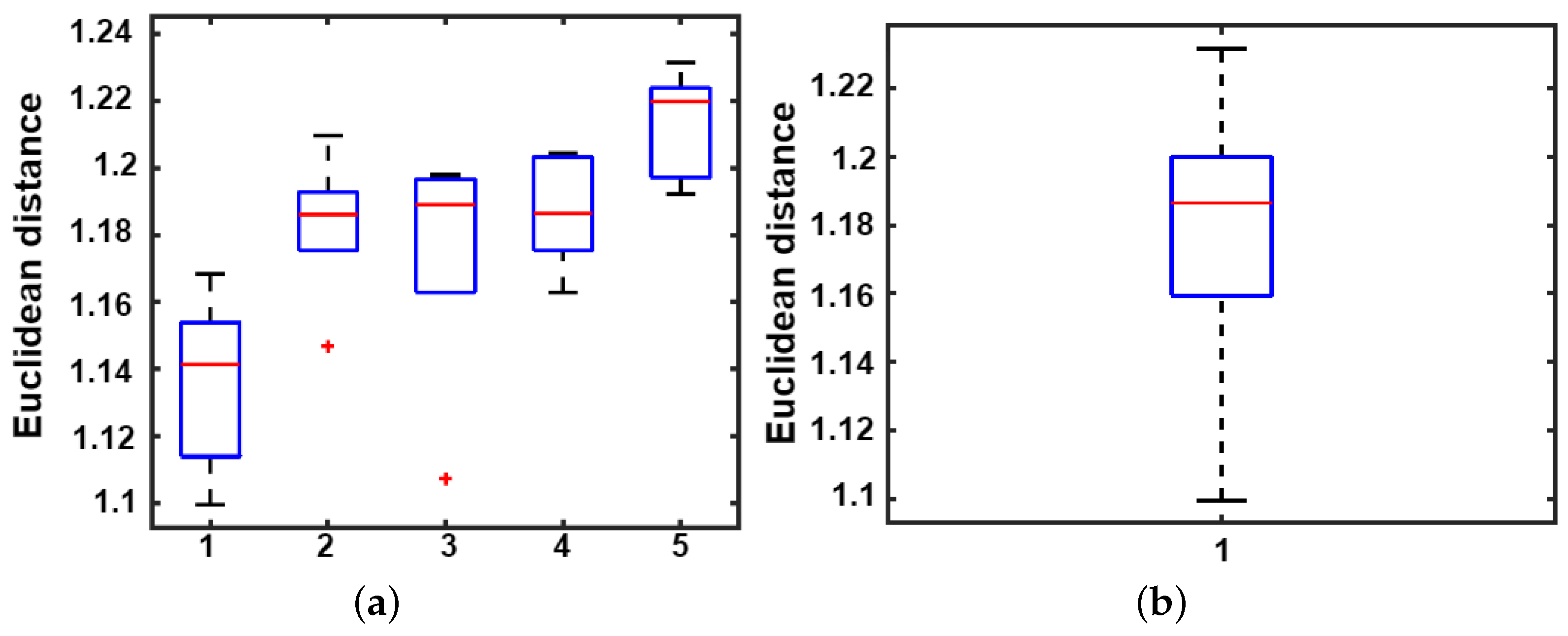
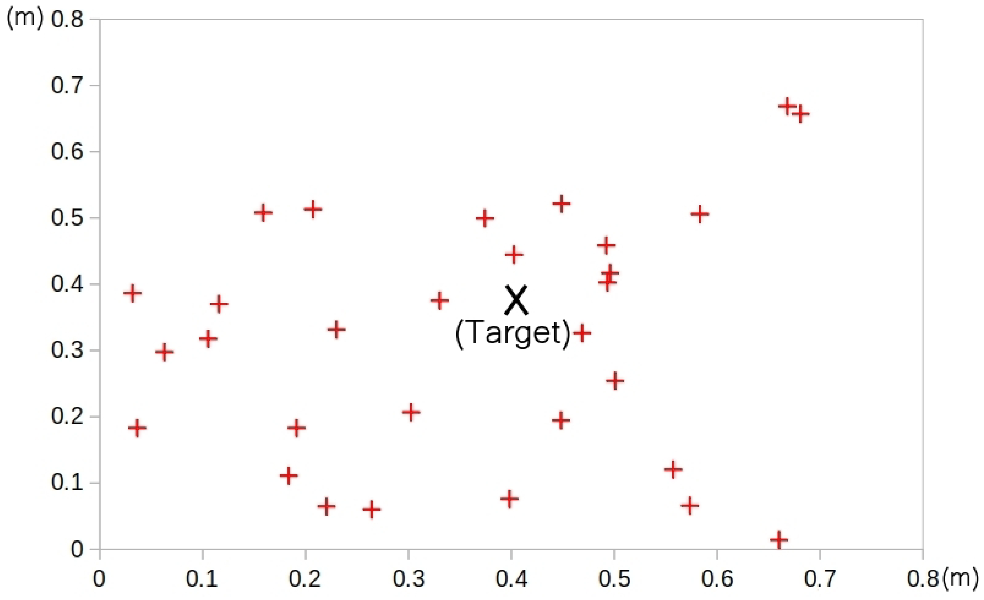
4.2.1. AR-Tag Absolute Error Measurements

An evaluation of the absolute position measurement of the tags captured inside the flight volume is presented in Table 1. An 11.0 × 11.0 cm tag was fixed on a stick with a 1.50 m height in front of the Tello drone camera. The UAS stays in a static position with a 2.30 m height with its camera aligned to the tag, in various positions inside a radius area of 5.0 m from the tag. The (X, Y and Z) position and Yaw orientation data captured by the AR-Tag Alvar package were stored and post-processed to calculate the absolute error mean and standard deviation. The absolute error is less than 1.90 cm for the X coordinate, 1.91 cm for the Y coordinate, 1.94 cm for the Z coordinate, and 2.61 degrees for the Yaw orientation, considering a 95% confidence interval for the measurements. The experiment results ensure that the arrangement provides accurate data to work on the UAS PID search and landing control algorithm.

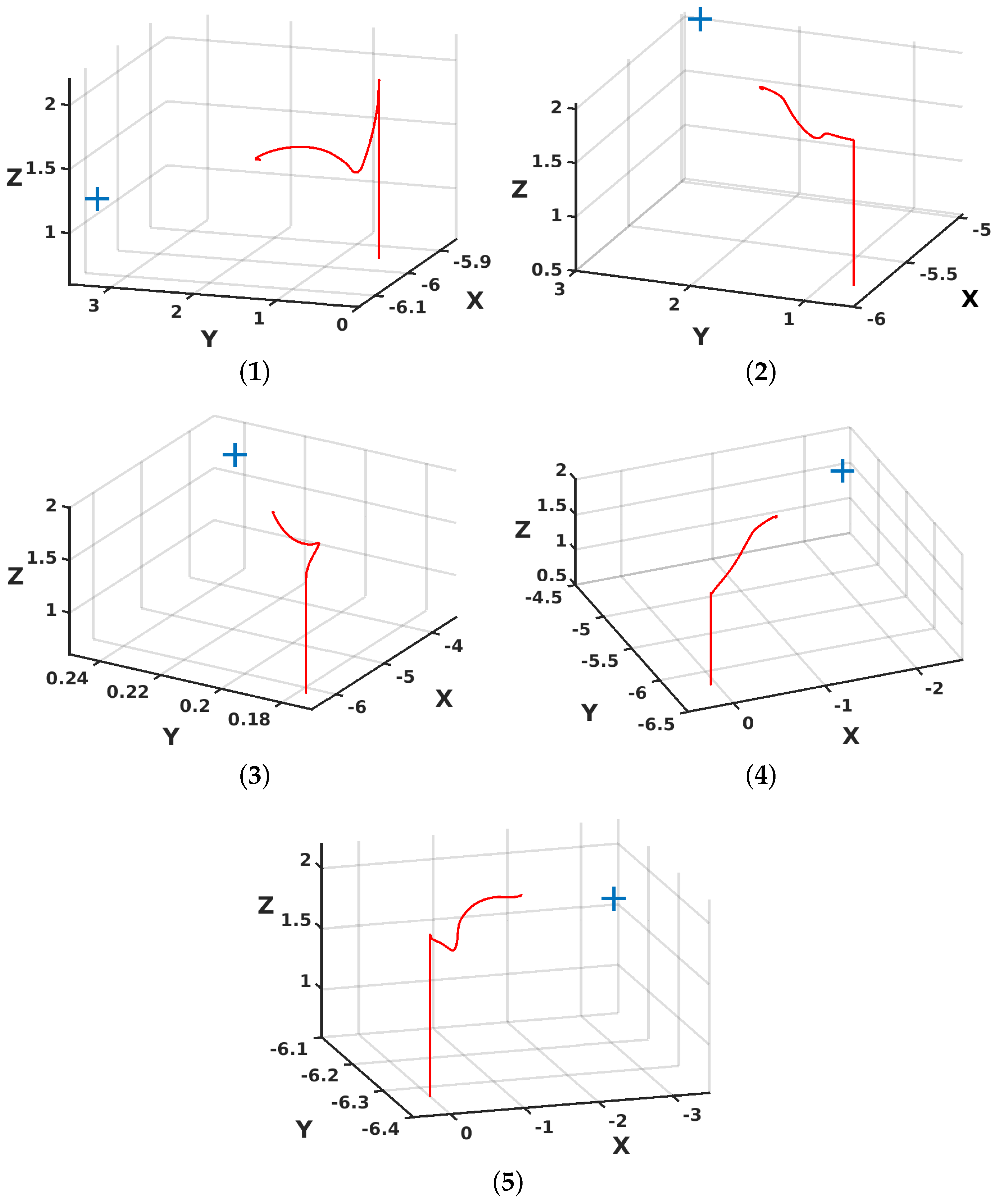
4.2.2. Base Search and Autonomous Landing Using the AR-Tag Position Readings

This experiment evaluated the final position error of the UAS after reaching the base and landing. The Tello drone executed ten rounds, three repetitions of a search and land operation, starting from different points and relative orientations from the tag. All of the start points remained inside the 5.0 m radius, which is considered as the work’s proper return and landing distance preset. The landing base has a 1.0 × 1.0 m size. After landing, a manual measurement of (X, Y) distances to the landing target evaluated the position error of the aircraft and the landing target. Figure 23 shows an example of these measurements.
The measured error (X, Y, Z) for all landing laps is shown in Figure 24. It is possible to observe in the graph that the landing zone was always respected in the conducted experiments. It is possible to conclude that the proposed technique is an adequate first approach. Other reference and position detection mechanisms may be implemented in a future version to improve the accuracy and safety of autonomous landing, making it possible to advance developing automatic battery replacement tools between UAS and UGV to meet long-range operations.

4.3. Discussion and Challenges

These research results evaluated different aspects necessary for cooperative heterogeneous autonomous robots in an agricultural scenario involving UAS and UGV systems. The outcomes demonstrated the feasibility of the proposed architecture by analyzing the image acquisition method for making the UAS land onto a UGV and the application of a fuzzy control strategy to make the UAS reach the insect trap safely and efficiently.
The proposed experimental architecture presents limitations for a real-world application. The simulated experiment considers an obstacle-free area to evaluate the visual control algorithm. However, it must be improved to consider the complex conditions presented in an olive culture area. First, the solution must work properly besides the complex agricultural farming scenarios, ground conditions, and obstacles in the flight route, among others. In addition, the UGV navigation must count with obstacle detection sensors and intelligent obstacle avoidance algorithms, allowing for the operation in various terrain. This application demands an off-road capability vehicle with a long-term working battery and payload to carry all of the sensors, hardware, and aerial vehicles in the inspection area.
Simulated vision-based control provides an initial evaluation of the trap detection and positioning algorithm. It is essential to consider that the real-world conditions are not similar to the simulation. An assessment of the proposed algorithm is required to increase the method’s reliability, mainly in an environment with the same characteristics as the olive culture areas. In addition, the UAS must also be able to detect and avoid obstacles during the displacements. A sensor architecture embedded in the UAS demands an aerial vehicle witha proper payload capability, increasing the size of the aircraft and the energy consumption. Implementing intelligent algorithms that allow for secure navigation near the olive trees and the search and landing on the mobile robot base is essential.
The perfect image capture of the traps is challenging due to the illumination variation and other interferences present from the UAS point-of-view. Considering that the fly trap is a paper, wind may move it and turn its face in the wrong direction at the moment of capture. In addition, branches in front of the trap are common, demanding an intelligent algorithm to correct these problems.

5. Conclusions and Future Work

This work proposed a solution for a multiple-cooperative robot architecture comprising UAS and UGV systems. The scenario chosen for testing this proposed approach was the inspection of olive grove inspect traps. The investigation detailed in this research work focused on executing a first evaluation of the UAS and UGV vision-based navigation and control algorithms, considering the specific real-world environmental conditions. In addition, this work also evaluated the UAS search and landing algorithm at the UGV roof based on a fiducial marker and vision-based processing. Experimental tests for the trap detection and position algorithm were conducted in a realistic simulation environment using ROS and CoppeliaSim platforms to verify the methodology’s performance. Real-world experiments were conducted to evaluate the proposed base search and landing algorithm.
The results demonstrated the multiple cooperative robot architecture approach’s feasibility in creating automatic trap data collection in the proposed environment. This architecture offers an enhanced data collection methodology for the fly infestation inspection process, decreasing this task’s time and labor demands compared with the traditional method. In future works, the authors intend to conduct the same test in a real-world scenario in which the quadrotor and the UGV will perform the tests autonomously, with proper embedded hardware and sensors to execute the planned tasks. Another future work is implementing the landing approach to charge the UAS, while this one is on the UGV’s roof, applying a long-term mission capability to the UAS vehicle in this operation.

Author Contributions

Conceptualization, G.S.B., M.T., A.C., J.L. and M.F.P.; methodology, G.S.B., M.T., A.C. and M.F.P.; validation, G.S.B., M.T. and A.C.; formal analysis, G.S.B., M.T., A.C. and M.F.P.; investigation, M.T. and A.C.; writing—original draft preparation, G.S.B., M.T., A.C. and M.F.P.; writing—review G.S.B., M.T., A.C., J.L., A.I.P., G.G.R.d.C., A.V. and M.F.P.; visualization, G.S.B., M.T., A.C. and M.F.P.; supervision, G.S.B., M.T., A.C. and M.F.P.; project administration, M.T. and A.C.; funding acquisition, J.L. All authors have read and agreed with the submission of the current manuscript version.

Funding

The authors would like to thank the following Brazilian Agencies CEFET-RJ, CAPES, CNPq, and FAPERJ. Besides, the authors also want to thank the Research Centre in Digitalization and Intelligent Robotics (CeDRI), Instituto Politécnico de Bragança (UIDB/05757/2020 and UIDP/05757/2020), Foundation for Science and Technology (FCT, Portugal) for financial support through national funds FCT/MCTES (PIDDAC) to CeDRI, Laboratório Associado para a Sustentabilidade e Tecnologia em Regiões de Montanha (SusTEC), IPB, Portugal, and INESC Technology and Science, Porto, Portugal. This work was carried out under the Project “OleaChain: Competências para a sustentabilidade e inovação da cadeia de valor do olival tradicional no Norte Interior de Portugal” (NORTE-06-3559- FSE-000188), an operation to hire highly qualified human resources, funded by NORTE 2020 through the European Social Fund (ESF).

Institutional Review Board Statement

Not applicable.

Informed Consent Statement

Not applicable.

Acknowledgments

The authors would like to thank the Foundation for Science and Technology (FCT, Portugal) for financial support through national funds FCT/MCTES (PIDDAC) to CeDRI (UIDB/05757/2020 and UIDP/05757/2020) and SusTEC (LA/P/0007/2021). In addition, the authors would like to thank the following Brazilian Agencies CEFET-RJ, CAPES, CNPq, and FAPERJ. In addition, the authors also want to thank the Research Centre in Digitalization and Intelligent Robotics (CeDRI), Instituto Politécnico de Braganca (IPB) - Campus de Santa Apolonia, Portugal, Laboratório Associado para a Sustentabilidade e Tecnologia em Regiões de Montanha (SusTEC), Portugal, INESC Technology and Science - Porto, Portugal and Universidade de Trás-os-Montes e Alto Douro - Vila Real, Portugal. This work was carried out under the Project “OleaChain: Competências para a sustentabilidade e inovação da cadeia de valor do olival tradicional no Norte Interior de Portugal” (NORTE-06-3559-FSE-000188), an operation used to hire highly qualified human resources, funded by NORTE 2020 through the European Social Fund (ESF).

Conflicts of Interest

The authors declare no conflict of interest.

Abbreviations

The following abbreviations are used in this manuscript:
IMUInertial Measurement Unit
FAOFood and Agriculture Organization
FCUFlight Controller Unit
MDPIMultidisciplinary Digital Publishing Institute
PIDProportional Integral Derivative
UASUnmanned Aerial System
UGVUnmanned Ground Vehicle
UNUnited Nations
ROSRobotic Operating System
SITLSoftware In The loop
SMCSliding Mode Control
FCKFFuzzy Complementary Kalman Filter
YOLOYou Only Look Once

References

  1. Mavridou, E.; Vrochidou, E.; Papakostas, G.A.; Pachidis, T.; Kaburlasos, V.G. Machine vision systems in precision agriculture for crop farming. J. Imaging 2019, 5, 89. [Google Scholar] [CrossRef] [Green Version]
  2. Xie, D.; Chen, L.; Liu, L.; Chen, L.; Wang, H. Actuators and Sensors for Application in Agricultural Robots: A Review. Machines 2022, 10, 913. [Google Scholar] [CrossRef]
  3. Khujamatov, K.E.; Toshtemirov, T.; Lazarev, A.; Raximjonov, Q. IoT and 5G technology in agriculture. In Proceedings of the 2021 International Conference on Information Science and Communications Technologies (ICISCT), Tashkent, Uzbekistan, 3–5 November 2021; IEEE: Piscataway, NJ, USA; pp. 1–6. [Google Scholar]
  4. Li, Z.; Xie, D.; Liu, L.; Wang, H.; Chen, L. Inter-row Information Recognition of Maize in Middle and Late Stages via LiDAR Supplementary Vision. Front. Plant Sci. 2022, 13, 1–14. [Google Scholar] [CrossRef]
  5. Milioto, A.; Lottes, P.; Stachniss, C. Real-time semantic segmentation of crop and weed for precision agriculture robots leveraging background knowledge in CNNs. In Proceedings of the 2018 IEEE International Conference on Robotics and Automation (ICRA), Brisbane, Australia, 21–28 May 2018; IEEE: Piscataway, NJ, USA; pp. 2229–2235. [Google Scholar]
  6. Carbone, C.; Garibaldi, O.; Kurt, Z. Swarm robotics as a solution to crops inspection for precision agriculture. KnE Eng. 2018, 2018, 552–562. [Google Scholar] [CrossRef] [Green Version]
  7. Gonzalez-de Santos, P.; Ribeiro, A.; Fernandez-Quintanilla, C.; Lopez-Granados, F.; Brandstoetter, M.; Tomic, S.; Pedrazzi, S.; Peruzzi, A.; Pajares, G.; Kaplanis, G.; et al. Fleets of robots for environmentally-safe pest control in agriculture. Precis. Agric. 2017, 18, 574–614. [Google Scholar] [CrossRef] [Green Version]
  8. Pereira, C.S.; Morais, R.; Reis, M.J. Recent advances in image processing techniques for automated harvesting purposes: A review. In Proceedings of the 2017 Intelligent Systems Conference (IntelliSys), London, UK, 7–8 September 2017; IEEE: Piscataway, NJ, USA; pp. 566–575. [Google Scholar]
  9. Biundini, I.Z.; Melo, A.G.; Pinto, M.F.; Marins, G.M.; Marcato, A.L.; Honorio, L.M. Coverage path planning optimization for slopes and dams inspection. In Proceedings of the Iberian Robotics conference, Porto, Portugal, 20–22 November 2019; Springer: Berlin/Heidelberg, Germany; pp. 513–523. [Google Scholar]
  10. Ramos, G.S.; Pinto, M.F.; Coelho, F.O.; Honório, L.M.; Haddad, D.B. Hybrid methodology based on computational vision and sensor fusion for assisting autonomous UAV on offshore messenger cable transfer operation. Robotica 2022, 40, 1–29. [Google Scholar] [CrossRef]
  11. Melo, A.G.; Andrade, F.A.; Guedes, I.P.; Carvalho, G.F.; Zachi, A.R.; Pinto, M.F. Fuzzy Gain-Scheduling PID for UAV Position and Altitude Controllers. Sensors 2022, 22, 2173. [Google Scholar] [CrossRef]
  12. de Castro, G.G.; Pinto, M.F.; Biundini, I.Z.; Melo, A.G.; Marcato, A.L.; Haddad, D.B. Dynamic Path Planning Based on Neural Networks for Aerial Inspection. J. Control. Autom. Electr. Syst. 2022, 34, 1–21. [Google Scholar] [CrossRef]
  13. Patrício, D.I.; Rieder, R. Computer vision and artificial intelligence in precision agriculture for grain crops: A systematic review. Comput. Electron. Agric. 2018, 153, 69–81. [Google Scholar] [CrossRef] [Green Version]
  14. Kakutani, K.; Matsuda, Y.; Nonomura, T.; Takikawa, Y.; Osamura, K.; Toyoda, H. Remote-controlled monitoring of flying pests with an electrostatic insect capturing apparatus carried by an unmanned aerial vehicle. Agriculture 2021, 11, 176. [Google Scholar] [CrossRef]
  15. Roosjen, P.P.; Kellenberger, B.; Kooistra, L.; Green, D.R.; Fahrentrapp, J. Deep learning for automated detection of Drosophila suzukii: Potential for UAV-based monitoring. Pest Manag. Sci. 2020, 76, 2994–3002. [Google Scholar] [CrossRef]
  16. Benheim, D.; Rochfort, S.; Robertson, E.; Potter, I.; Powell, K. Grape phylloxera (Daktulosphaira vitifoliae)–a review of potential detection and alternative management options. Ann. Appl. Biol. 2012, 161, 91–115. [Google Scholar] [CrossRef]
  17. Vanegas, F.; Bratanov, D.; Powell, K.; Weiss, J.; Gonzalez, F. A novel methodology for improving plant pest surveillance in vineyards and crops using UAV-based hyperspectral and spatial data. Sensors 2018, 18, 260. [Google Scholar] [CrossRef] [Green Version]
  18. Albani, D.; IJsselmuiden, J.; Haken, R.; Trianni, V. Monitoring and mapping with robot swarms for agricultural applications. In Proceedings of the 2017 14th IEEE International Conference on Advanced Video and Signal Based Surveillance (AVSS), Madrid, Spain, 29 November–2 December 2017; IEEE: Piscataway, NJ, USA; pp. 1–6. [Google Scholar]
  19. Mammarella, M.; Comba, L.; Biglia, A.; Dabbene, F.; Gay, P. Cooperative Agricultural Operations of Aerial and Ground Unmanned Vehicles. IEEE Int. Workshop Metrol. Agric. For. 2020, 224–229. [Google Scholar]
  20. Madridano, Á.; Al-Kaff, A.; Flores, P.; Martín, D.; de la Escalera, A. Software architecture for autonomous and coordinated navigation of uav swarms in forest and urban firefighting. Appl. Sci. 2021, 11, 1258. [Google Scholar] [CrossRef]
  21. Shi, Y.; Wang, N.; Zheng, J.; Zhang, Y.; Yi, S.; Luo, W.; Sycara, K. Adaptive informative sampling with environment partitioning for heterogeneous multi-robot systems. In Proceedings of the 2020 IEEE/RSJ International Conference on Intelligent Robots and Systems (IROS), Las Vegas, NV, USA, 25–29 October 2020; IEEE: Piscataway, NJ, USA; pp. 11718–11723. [Google Scholar]
  22. Narváez, E.; Ravankar, A.A.; Ravankar, A.; Emaru, T.; Kobayashi, Y. Autonomous vtol-uav docking system for heterogeneous multirobot team. IEEE Trans. Instrum. Meas. 2020, 70, 1–18. [Google Scholar] [CrossRef]
  23. Sinnemann, J.; Boshoff, M.; Dyrska, R.; Leonow, S.; Mönnigmann, M.; Kuhlenkötter, B. Systematic literature review of applications and usage potentials for the combination of unmanned aerial vehicles and mobile robot manipulators in production systems. Prod. Eng. 2022, 16, 579–596. [Google Scholar] [CrossRef]
  24. Rizk, Y.; Awad, M.; Tunstel, E.W. Cooperative heterogeneous multi-robot systems: A survey. ACM Comput. Surv. (CSUR) 2019, 52, 1–31. [Google Scholar] [CrossRef]
  25. Fu, M.; Zhang, K.; Yi, Y.; Shi, C. Autonomous landing of a quadrotor on an UGV. In Proceedings of the 2016 IEEE International Conference on Mechatronics and Automation, Harbin, China, 7–10 August 2016; IEEE: Piscataway, NJ, USA; pp. 988–993. [Google Scholar]
  26. Chen, X.; Phang, S.K.; Shan, M.; Chen, B.M. System integration of a vision-guided UAV for autonomous landing on moving platform. In Proceedings of the 2016 12th IEEE International Conference on Control and Automation (ICCA), Kathmandu, Nepal, 1–3 June 2016; IEEE: Piscataway, NJ, USA; pp. 761–766. [Google Scholar]
  27. FAO. The future of food and agriculture–Trends and challenges. Annu. Rep. 2017, 296, 1–180. [Google Scholar]
  28. Kim, W.S.; Lee, W.S.; Kim, Y.J. A review of the applications of the internet of things (IoT) for agricultural automation. J. Biosyst. Eng. 2020, 45, 385–400. [Google Scholar] [CrossRef]
  29. Jha, K.; Doshi, A.; Patel, P.; Shah, M. A comprehensive review on automation in agriculture using artificial intelligence. Artif. Intell. Agric. 2019, 2, 1–12. [Google Scholar] [CrossRef]
  30. Lattanzi, D.; Miller, G. Review of Robotic Infrastructure Inspection Systems. J. Infrastruct. Syst. 2017, 23. [Google Scholar] [CrossRef]
  31. Coelho, F.O.; Pinto, M.F.; Souza, J.P.C.; Marcato, A.L. Hybrid methodology for path planning and computational vision applied to autonomous mission: A new approach. Robotica 2020, 38, 1000–1018. [Google Scholar] [CrossRef]
  32. Chebrolu, N.; Läbe, T.; Stachniss, C. Robust long-term registration of UAV images of crop fields for precision agriculture. IEEE Robot. Autom. Lett. 2018, 3, 3097–3104. [Google Scholar] [CrossRef]
  33. Pinto, M.F.; Coelho, F.O.; De Souza, J.P.; Melo, A.G.; Marcato, A.L.; Urdiales, C. Ekf design for online trajectory prediction of a moving object detected onboard of a uav. In Proceedings of the 2018 13th APCA International Conference on Automatic Control and Soft Computing (CONTROLO), Ponta Delgada, Portugal, 4–6 June 2018; IEEE: Piscataway, NJ, USA; pp. 407–412. [Google Scholar]
  34. Pathmakumar, T.; Kalimuthu, M.; Elara, M.R.; Ramalingam, B. An autonomous robot-aided auditing scheme for floor cleaning. Sensors 2021, 21, 4332. [Google Scholar] [CrossRef]
  35. Azeta, J.; Bolu, C.; Hinvi, D.; Abioye, A.; Boyo, H.; Anakhu, P.; Onwordi, P. An android based mobile robot for monitoring and surveillance. Procedia Manuf. 2019, 35, 1129–1134. [Google Scholar] [CrossRef]
  36. Bayati, M.; Fotouhi, R. A mobile robotic platform for crop monitoring. Adv. Robot. Autom. 2018, 7, 1000186. [Google Scholar] [CrossRef]
  37. Maciel, G.M.; Pinto, M.F.; Júnior, I.C.d.S.; Coelho, F.O.; Marcato, A.L.; Cruzeiro, M.M. Shared control methodology based on head positioning and vector fields for people with quadriplegia. Robotica 2022, 40, 348–364. [Google Scholar] [CrossRef]
  38. Kulbacki, M.; Segen, J.; Knieć, W.; Klempous, R.; Kluwak, K.; Nikodem, J.; Kulbacka, J.; Serester, A. Survey of drones for agriculture automation from planting to harvest. In Proceedings of the 2018 IEEE 22nd International Conference on Intelligent Engineering Systems (INES), Las Palmas de Gran Canaria, Spain, 21–23 June 2018; IEEE: Piscataway, NJ, USA; pp. 353–358. [Google Scholar]
  39. Manfreda, S.; McCabe, M.F.; Miller, P.E.; Lucas, R.; Pajuelo Madrigal, V.; Mallinis, G.; Ben Dor, E.; Helman, D.; Estes, L.; Ciraolo, G.; et al. On the use of unmanned aerial systems for environmental monitoring. Remote Sens. 2018, 10, 641. [Google Scholar] [CrossRef] [Green Version]
  40. Maes, W.H.; Steppe, K. Perspectives for remote sensing with unmanned aerial vehicles in precision agriculture. Trends Plant Sci. 2019, 24, 152–164. [Google Scholar] [CrossRef]
  41. Hajjaj, S.S.H.; Sahari, K.S.M. Review of research in the area of agriculture mobile robots. In Proceedings of the 8th International Conference on Robotic, Vision, Signal Processing & Power Applications, Penang, Malaysia, 10–12 November 2013; Springer: Berlin/Heidelberg, Germany; pp. 107–117. [Google Scholar]
  42. Lytridis, C.; Kaburlasos, V.G.; Pachidis, T.; Manios, M.; Vrochidou, E.; Kalampokas, T.; Chatzistamatis, S. An Overview of Cooperative Robotics in Agriculture. Agronomy 2021, 11, 1818. [Google Scholar] [CrossRef]
  43. Kim, P.; Price, L.C.; Park, J.; Cho, Y.K. UAV-UGV cooperative 3D environmental mapping. In Proceedings of the ASCE International Conference on Computing in Civil Engineering, Atlanta, GA, USA, 17–19 June 2019. [Google Scholar]
  44. Maini, P.; Sujit, P. On cooperation between a fuel constrained UAV and a refueling UGV for large scale mapping applications. In Proceedings of the 2015 International Conference on Unmanned Aircraft Systems (ICUAS), Denver, CO, USA, 9–12 June 2015; IEEE: Piscataway, NJ, USA; pp. 1370–1377. [Google Scholar]
  45. Arbanas, B.; Ivanovic, A.; Car, M.; Haus, T.; Orsag, M.; Petrovic, T.; Bogdan, S. Aerial-ground robotic system for autonomous delivery tasks. In Proceedings of the 2016 IEEE International Conference on Robotics and Automation (ICRA), Stockholm, Sweden, 16–21 May 2016; IEEE: Piscataway, NJ, USA; pp. 5463–5468. [Google Scholar]
  46. Alam, M.S.; Oluoch, J. A survey of safe landing zone detection techniques for autonomous unmanned aerial vehicles (UAVs). Expert Syst. Appl. 2021, 179, 115091. [Google Scholar] [CrossRef]
  47. Jin, S.; Zhang, J.; Shen, L.; Li, T. On-board vision autonomous landing techniques for quadrotor: A survey. In Proceedings of the 2016 35th Chinese Control Conference (CCC), Chengdu, China, 27–29 July 2016; IEEE: Piscataway, NJ, USA; pp. 10284–10289. [Google Scholar]
  48. Khazetdinov, A.; Zakiev, A.; Tsoy, T.; Svinin, M.; Magid, E. Embedded ArUco: A novel approach for high precision UAV landing. In Proceedings of the 2021 International Siberian Conference on Control and Communications (SIBCON), Kazan, Russia, 13–15 May 2021; IEEE: Piscataway, NJ, USA; pp. 1–6. [Google Scholar]
  49. Polvara, R.; Sharma, S.; Wan, J.; Manning, A.; Sutton, R. Towards autonomous landing on a moving vessel through fiducial markers. In Proceedings of the 2017 European Conference on Mobile Robots (ECMR), Paris, France, 6–8 September 2017; IEEE: Piscataway, NJ, USA; pp. 1–6. [Google Scholar]
  50. Kumar, A. Real-time performance comparison of vision-based autonomous landing of quadcopter on a ground moving target. IETE J. Res. 2021, 1–18. [Google Scholar] [CrossRef]
  51. Yang, Q.; Sun, L. A fuzzy complementary Kalman filter based on visual and IMU data for UAV landing. Optik 2018, 173, 279–291. [Google Scholar] [CrossRef]
  52. Kim, J.; Jung, Y.; Lee, D.; Shim, D.H. Outdoor autonomous landing on a moving platform for quadrotors using an omnidirectional camera. In Proceedings of the 2014 International Conference on Unmanned Aircraft Systems (ICUAS), Orlando, FL, USA, 27–30 May 2014; IEEE: Piscataway, NJ, USA; pp. 1243–1252. [Google Scholar]
  53. Yang, S.; Ying, J.; Lu, Y.; Li, Z. Precise quadrotor autonomous landing with SRUKF vision perception. In Proceedings of the 2015 IEEE International Conference on Robotics and Automation (ICRA), Seattle, WA, USA, 26–30 May 2015; IEEE: Piscataway, NJ, USA; pp. 2196–2201. [Google Scholar]
  54. Yang, S.; Scherer, S.A.; Schauwecker, K.; Zell, A. Autonomous landing of MAVs on an arbitrarily textured landing site using onboard monocular vision. J. Intell. Robot. Syst. 2014, 74, 27–43. [Google Scholar] [CrossRef] [Green Version]
  55. Acuna, R.; Willert, V. Dynamic Markers: UAV landing proof of concept. In Proceedings of the 2018 Latin American Robotic Symposium, 2018 Brazilian Symposium on Robotics (SBR) and 2018 Workshop on Robotics in Education (WRE), Joao Pessoa, Brazil, 6–10 November 2018; IEEE: Piscataway, NJ, USA; pp. 496–502. [Google Scholar]
  56. Augustinos, A.; Stratikopoulos, E.; Zacharopoulou, A.; Mathiopoulos, K. Polymorphic microsatellite markers in the olive fly, Bactrocera oleae. Mol. Ecol. Notes 2002, 2, 278–280. [Google Scholar] [CrossRef]
  57. Nardi, F.; Carapelli, A.; Dallai, R.; Roderick, G.K.; Frati, F. Population structure and colonization history of the olive fly, Bactrocera oleae (Diptera, Tephritidae). Mol. Ecol. 2005, 14, 2729–2738. [Google Scholar] [CrossRef]
  58. Gonçalves, F.; Torres, L. The use of trap captures to forecast infestation by the olive fly, Bactrocera oleae (Rossi) (Diptera: Tephritidae), in traditional olive groves in north-eastern Portugal. Int. J. Pest Manag. 2013, 59, 279–286. [Google Scholar] [CrossRef]
  59. Sparrow, R.; Howard, M. Robots in agriculture: Prospects, impacts, ethics, and policy. Precis. Agric. 2021, 22, 818–833. [Google Scholar] [CrossRef]
  60. Mamdouh, N.; Khattab, A. YOLO-Based Deep Learning Framework for Olive Fruit Fly Detection and Counting. IEEE Access 2021, 9, 84252–84262. [Google Scholar] [CrossRef]
  61. Beyaz, A.; Martínez Gila, D.M.; Gómez Ortega, J.; Gámez García, J. Olive fly sting detection based on computer vision. Postharvest Biol. Technol. 2019, 150, 129–136. [Google Scholar] [CrossRef]
  62. Shaked, B.; Amore, A.; Ioannou, C.; Valdés, F.; Alorda, B.; Papanastasiou, S.; Goldshtein, E.; Shenderey, C.; Leza, M.; Pontikakos, C.; et al. Electronic traps for detection and population monitoring of adult fruit flies (Diptera: Tephritidae). J. Appl. Entomol. 2018, 142, 43–51. [Google Scholar] [CrossRef]
  63. López-Villalta, M.C. Olive Pest and Disease Management; International Olive Oil Council Madrid: Madrid, Spain, 1999. [Google Scholar]
  64. Hiemann, A.; Kautz, T.; Zottmann, T.; Hlawitschka, M. Enhancement of Speed and Accuracy Trade-Off for Sports Ball Detection in Videos—Finding Fast Moving, Small Objects in Real Time. Sensors 2021, 21, 3214. [Google Scholar] [CrossRef]
  65. de Oliveira Junior, A.; Piardi, L.; Bertogna, E.G.; Leitao, P. Improving the Mobile Robots Indoor Localization System by Combining SLAM with Fiducial Markers. In Proceedings of the 2021 Latin American Robotics Symposium (LARS), 2021 Brazilian Symposium on Robotics (SBR), and 2021 Workshop on Robotics in Education (WRE), Natal, Brazil, 11–15 October 2021; pp. 234–239. [Google Scholar] [CrossRef]
  66. Niekum, S. ar_track_alvar Ros Package Wiki. 2016. Available online: http://wiki.ros.org/ar_track_alvar (accessed on 15 January 2022).
  67. Enterprise, D. DJI Tello. 2022. Available online: https://m.dji.com/pt/product/tello (accessed on 15 January 2022).
  68. Wang, C.Y.; Bochkovskiy, A.; Liao, H.Y.M. YOLOv7: Trainable bag-of-freebies sets new state-of-the-art for real-time object detectors. arXiv 2022, arXiv:2207.02696. [Google Scholar]
  69. Wu, D.; Jiang, S.; Zhao, E.; Liu, Y.; Zhu, H.; Wang, W.; Wang, R. Detection of Camellia oleifera Fruit in Complex Scenes by Using YOLOv7 and Data Augmentation. Appl. Sci. 2022, 12, 11318. [Google Scholar] [CrossRef]
  70. Lin, T.Y.; Maire, M.; Belongie, S.; Hays, J.; Perona, P.; Ramanan, D.; Dollár, P.; Zitnick, C.L. Microsoft coco: Common objects in context. In Proceedings of the European Conference on Computer Vision, Tel Aviv, Israel, 8–14 September 2014; Springer: Berlin/Heidelberg, Germany; pp. 740–755. [Google Scholar]
  71. Rohmer, E.; Singh, S.P.; Freese, M. V-REP: A versatile and scalable robot simulation framework. In Proceedings of the 2013 IEEE/RSJ International Conference on Intelligent Robots and Systems, Tokyo, Japan, 3–7 November 2013; IEEE: Piscataway, NJ, USA; pp. 1321–1326. [Google Scholar]
  72. Ferro, M.; Mirante, A.; Ficuciello, F.; Vendittelli, M. A CoppeliaSim Dynamic Dimulator for the da Vinci Research Kit. IEEE Robot. Autom. Lett. 2022, 8, 129–136. [Google Scholar] [CrossRef]
  73. Robotics, C. Husky-unmanned ground vehicle. In Technical Specifications; Clearpath Robotics: Kitcener, ON, Canada, 2013; Available online: https://clearpathrobotics.com/husky-unmanned-ground-vehicle-robot/ (accessed on 15 January 2022).
Figure 1. Arrangement of olive groves in the cultivation zone (left), yellow chromotropic trap (centre), and positioning of the trap carried out by the operator on the ground (right).
Agriculture 13 00239 g001
Figure 2. Image capture of the trap at three different distances. (a) 3.5 m with 5× digital zoom in detail; (b) 1.5 m with 2× digital zoom in detail; (c) 0.30 m with no digital zoom.
Agriculture 13 00239 g002
Figure 3. Overview of the proposed methodology.
Agriculture 13 00239 g003
Figure 4. Flowchart of the proposed methodology steps.
Agriculture 13 00239 g004
Figure 5. YOLO providing the object detection. Note that the code extracts the objected center and its extremities, given the object occupancy in the image.
Agriculture 13 00239 g005
Figure 6. Flowchart of the UGV behavior.
Agriculture 13 00239 g006
Figure 7. Splits in the image made for the detection of t r a p _ p o s _ U G V . This value is informed to the UAS to start the trap search process.
Agriculture 13 00239 g007
Figure 8. Overview of the UAS control strategy.
Agriculture 13 00239 g008
Figure 9. UAS performing take-off from the UGV and maintaining a minim distance. After the z _ l i n e a r adjustment, the UAS performs a z _ a n g u l a r adjustment according to the trap’s position.
Agriculture 13 00239 g009
Figure 10. Inputs and output of the fuzzy controller.
Agriculture 13 00239 g010
Figure 11. Input fuzzification.
Agriculture 13 00239 g011
Figure 12. Output fuzzification.
Agriculture 13 00239 g012
Figure 13. System’s surface behavior. (a). Centering the robot’s angle concerning the trap. (b) and (c) Equipment linear speed in the x _ a x i s .
Agriculture 13 00239 g013
Figure 14. Image of the landing base and the AR-tag with the Tello drone moving toward it.
Agriculture 13 00239 g014
Figure 15. Simulated environment developed to validate the proposed strategy.
Agriculture 13 00239 g015
Figure 16. UGV model used in this work.
Agriculture 13 00239 g016
Figure 17. UGV validation strategy.
Agriculture 13 00239 g017
Figure 18. Euclidean distance between the UGV and the trap for the UGV validation. (a) Presents a box plot per experiment. (b) Single graph with data from all experiments.
Agriculture 13 00239 g018
Figure 19. Traps position for the UAS validation.
Agriculture 13 00239 g019
Figure 20. Euclidean distance between the UAS and the trap for the UAS validation. (a) Presents a box plot per experiment. (b) Single graph with data from all experiments.
Agriculture 13 00239 g020
Figure 21. (a) UAS view when reaching the objective. (b) UAS position relative to the trap.
Agriculture 13 00239 g021
Figure 22. Trap position in relation to the UAS and UGV initial position. (1) Trap at 70 degrees left. (2) Trap at 30 degrees left. (3) Trap at center. (4) Trap at 30 degrees right. (5) Trap at 70 degrees right.
Agriculture 13 00239 g022
Figure 23. Manual position landing error measurement example.
Agriculture 13 00239 g023
Figure 24. Landing error measurements for the 10-round landing experiments.
Agriculture 13 00239 g024
Table 1. Mean and standard deviation for X and Y tag measurements.
Starting Point
X; Y (m)
X
Mean
X
Std
Y
Mean
Y
Std
0.0; 2.01.510.151.280.32
1.0; 3.02.330.331.900.12
2.0; 2.02.620.422.210.44
3.0; 2.03.100.201.870.37
3.0; −3.03.450.422.850.34
95 %
confidence
interval
2.60\pm 0.822.02\pm 0.85
Disclaimer/Publisher’s Note: The statements, opinions and data contained in all publications are solely those of the individual author(s) and contributor(s) and not of MDPI and/or the editor(s). MDPI and/or the editor(s) disclaim responsibility for any injury to people or property resulting from any ideas, methods, instructions or products referred to in the content.

