Heat Recovery Systems for Agricultural Vehicles: Utilization Ways and Their Efficiency


1
Institute of Technical Science, University of Opole, Dmowskiego str. 7-9, 45-365 Opole, Poland
2
Department of Tractors and Agricultural Machinery, Operating and Maintenance, Mykolayiv National Agrarian University (Ukraine), 9 Georgiy Gongadze Str., 54020 Mykolayiv, Ukraine
*
Author to whom correspondence should be addressed.
Agriculture 2018, 8(12), 199; https://doi.org/10.3390/agriculture8120199
Submission received: 27 October 2018
/
Revised: 29 November 2018
/
Accepted: 8 December 2018
/
Published: 12 December 2018
(This article belongs to the Special Issue Advances in Agriculture Mechanization)
Abstract
:The focus of today’s agriculture is to reduce fuel consumption and pollutant emission. More than 50% of the fuel energy is lost with the exhaust gas and coolant of diesel engines. Therefore, waste heat recovery systems are a promising concept to meet economical and ecological requirements. Agricultural vehicles have an operating cycle that is quite different from on-road trucks (higher engine load factor and less annual utilization). This has influence on the efficiency of waste heat recovery. The purpose of this paper was to analyze different waste heat recovery technologies to be used in agricultural applications. In the study, technical and economic indicators have been used. According to suggested classification, four pathways for utilization were studied. Turbocompounding, electric turbocompounding, and heating of transmission oil for hydraulic clutch gearboxes have proved to be effective for agricultural vehicles. For the economical conditions of the European Union (EU), a turbocompounding diesel engine is acceptable if agricultural tractor rated power is more than 275 kW, and combine harvester rated power is more than 310 kW. In cold climates, heat recovery transmission warm-up may be recommended. Waste heat absorption refrigerators have proven to be a viable technology for air conditioning and intake air cooling systems.
1. Introduction
Agriculture, especially crop production, is an energy-intensive industry. Heavy-duty diesel engines (HDDE) of agricultural vehicles are among the main contributors to harmful emissions. Therefore, energy saving technologies and energy effective machines needed to be developed and put into practice. For this reason, engine manufacturers work to increase their energy efficiency, fuel costs and emission reduction. They follow several strategies: alternative fuels application [1]; increasing engine thermal performance [2,3]; and engine bottoming technologies [4].
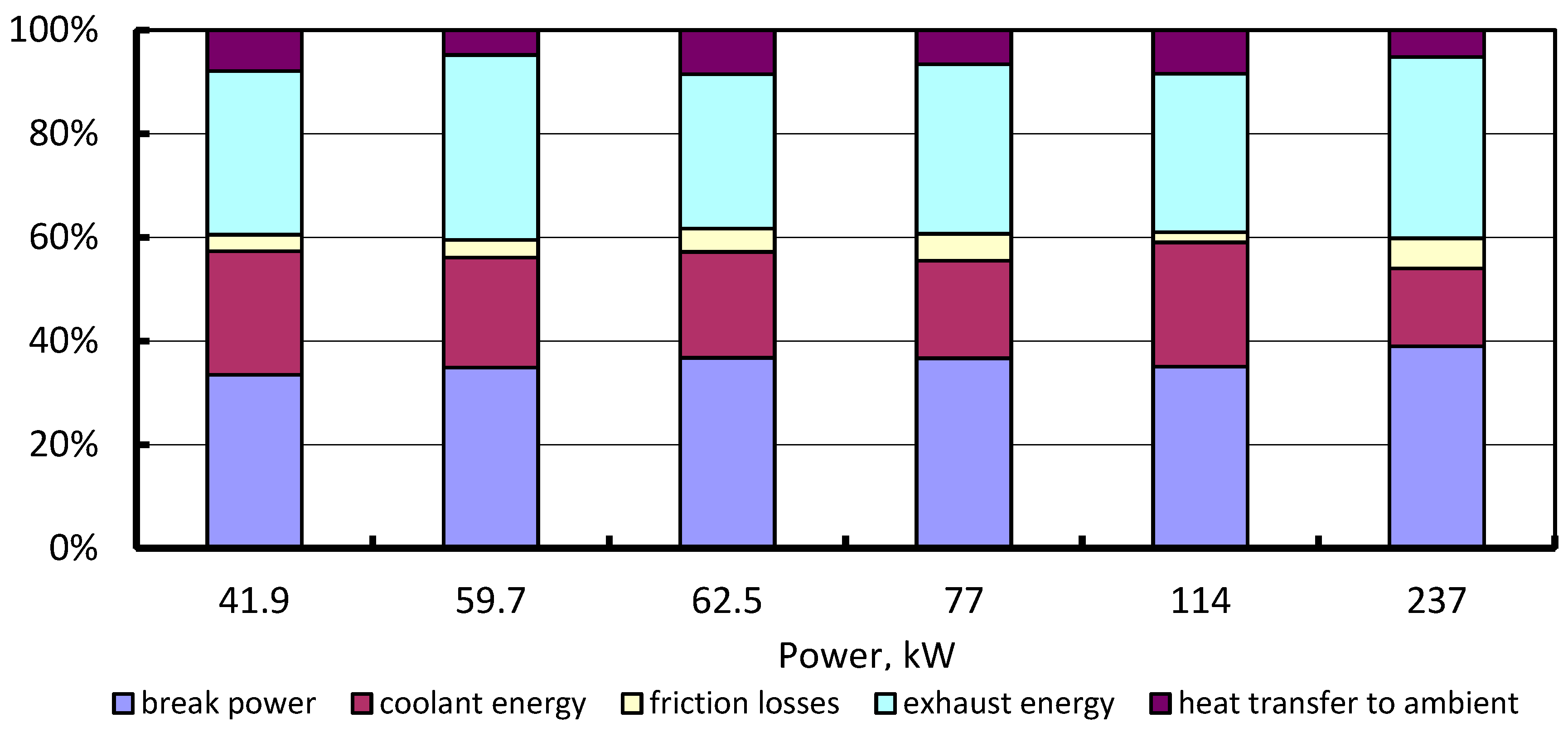
The modern HDDEs of agricultural machinery have relatively low efficiency. A significant part of fuel energy is lost with exhaust gases (Figure 1).
Right here, there is the potential to improve the engine economy. Engine bottoming technologies or waste heat recovery technologies are under development. The organic Rankine cycle, turbo-compounding, thermoelectric generators, and so on, belong to the above. Waste heat recovery systems have been adopted for marine and stationary power plants. However, their application for agriculture has not been sufficiently investigated.
Engineering companies (Scania, Ford, BMW, Cummins, Navistar Advanced Technology, etc.) and associated research centers are engaged in the study and development of waste heat recovery systems for vehicles. Navistar Inc. considers it as one of the main components to achieving an ambitious goal—diesel engine efficiency of 55% [7].
The typical operating cycle of agricultural tractors and combine harvesters is quite different as compared with on-road trucks. The average load factor for on-road trucks amounts to 0.23 [8]. Their annual hours of operation range from 2400 to 4000 [9]. The agricultural tractors and combine harvester diesel engines run most of the time at 75–90% of load [10,11] and their annual utilization is substantially less [12,13].
In general, heat recovery technologies were classified within three domains: exhaust gas temperature; equipment; and recovery purpose [14]. The main heat sources in HDDE are categorized into two classes: high-temperature heat sources (exhaust gases) and low-temperature sources (coolant, lube oil, and charge air cooling) [10]. The benefits of waste heat recovery are classified into two categories: direct benefits (reduction of fuel consumption) and indirect benefits (reduction in pollution, reduction in auxiliary energy consumption, etc.) [15]. Possible ways of using heat recovery technologies for internal combustion engines were selected by J.S. Jadhao and D.G. Thombare [16]. The dominating ones are heating purpose, electric power generation, mechanical work, and refrigeration. There are classifications of heat utilization systems, involving their advantages and description of heat recovery methods for heat engines [17]. However, they are general and do not take into account the peculiarities of the operation of agricultural machinery. This complicates their overall analysis and suitability.
The aim of this study is to clarify the classification of the waste heat recovery systems and to determine the profitable directions of their application by agricultural tractors and combine harvesters.
2. Materials
In the study, some indicators were used: technical (exhaust gas energy utilization factor Ψg; coolant energy utilization factor Ψc; specific power of a utilization machine (device)) and economic (return, investment, and simple payback period).
The exhaust gas energy utilization factor is equal to:
where Tg is the exhaust gas temperature, K; Ta is the ambient temperature, K; and Tb is the outlet temperature of an exhaust gas after heat recovery system, K.
The coolant energy of an engine can be used for the purpose of heating, such as space heating, preheating fuel, and so on. The coolant energy utilization factor is calculated as:
where TP1 is the coolant temperature at the engine outlet, K; TP2 is the coolant temperature at the engine inlet, K; and Th is the coolant temperature at the waste heat recovery exchanger outlet, K.
The exhaust gas temperature has to be higher than the dew point temperature of sulphuric acid vapors. Thus, the permissible minimum exhaust gas outlet temperature is determined as follows:
where TS is the dew point temperature of steam, K; S is the sulfur content in diesel fuel, %; and ΔTS is the temperature reserve, ΔTS = 25 K.
We propose to use the total waste heat utilization factor. It assesses the energy efficiency of the heat recovery system. It is a ratio of its power to total input fuel energy, and is calculated as:
where Phr is the power of the waste heat recovery machine (device), kW; ηe is the efficiency of a diesel engine; and Pe is the rated power of the engine, kW.
The capacity of the waste heat absorption refrigerator can be determined as:
where ε is the coefficient of performance; Geg is the mass flow of exhaust gases, kg/s; and Cpg is the heat capacity of exhaust gases, kJ/(kg·K).
Standard methods were used to evaluate the efficiency of an engine at different intake temperatures [18]. Economic evaluation has been carried out by means of the determination of a simple payback period and maximum acceptable investment costs.
3. Results
We propose to classify heat recovery systems according to their applications:
- (1)
- Mechanical work;
- (2)
- Electricity generation;
- (3)
- Heating and cooling generation.
3.1. Mechanical Work
The principle methods for exhaust gas recovery use either kinetic energy flow or thermal energy flow (Figure 2). The kinetic energy flow can be transformed by a power turbine. It can either provide additional power to an engine (mechanical turbocompounding) or generate electricity (electrical turbocompounding). A number of companies (Volvo, Iveco, Caterpillar, Cummins, Scania, Detroit Diesel, etc.) work out the above technologies [19,20,21,22].
3.1.1. Turbocompounding
The use of mechanical turbocompounding systems allows reduction in the specific fuel consumption (at the nominal power mode) by 4.7–7.5% [20,21,22,23]. The minimum rated power of a mechanical turbocompounding engine (currently in operation) is 235 kW (Diesel DSC1121 (Scania AB, Södertälje, Sweden), with the specific fuel consumption of 195 g/kWh). MTU, Detroit Diesel, Mack Truck and Volvo manufacture more powerful engines: MTU 6R 1500—400–460 kW; DD15—334–411 kW; MP8 Mack Truck—334 kW; D13TC—312.8 kW [23,24,25,26].
The power-turbine power depends on the rated power of the diesel engine and its load. According to Caterpillar Inc.’s research data, this function is not linear. (Figure 3) [27].
The main disadvantage of turbocompounding equipment is a relatively high cost (mainly due to a special hydro mechanical transmission). That is why the use of a power turbine to drive a fan of a diesel cooling system is of practical interest. The fan consumes up to 7% of diesel effective power. It is close enough to the power-turbine power. For a diesel engine (rated power—397 kW), it has been established that the use of a turbofan can provide a reduction of the specific fuel consumption (rated power—5.9%; 45% load factor—1.5%) [28].
3.1.2. Rankine Cycle
For a waste heat recovery system, the Rankine cycle began to be studied in the 1970s. These studies were funded by the US Department of Energy and were sponsored by Mack Trucks and Thermo Electron Corporation [29].
Today, a number of companies (AVL PowerTrain Engineering, Inc.; BMW; Cummins; Navistar Advanced Technology; etc.) study and develop this technology. According to the study, the Rankine cycle utilization system can provide a reduction of the specific fuel consumption by 11% [30].
Engineers from BMW have tested a car with a waste heat recovery steam engine. It was named Turbosteamer and adapted for the BMW 3 Series car. This allowed reducing the specific fuel consumption by 15% [31]. Organic Rankine cycle systems are currently in commercial use in marine and stationary power plants. Agricultural vehicle applications are currently in the research phase and are expected to enter the market around 2020 [4].
3.1.3. Economic Efficiency
Let us consider the efficiency of waste heat recovery systems. The simple payback period depends on the investment costs and return,
where R is the return, USD/year; IR is the investment cost, USD; and OE is the annual operating cost, USD.
The investment costs are USD (2000–3400) for the turbocompounding diesels [22] and EUR (2000–3000) for the Rankine organic cycle [31]. Operating annual costs for the last device are EUR100.
The return is determined by the formula:
where Δbe is the reduction of specific fuel consumption, kg/kWh; Pe is the rated power, kW; Lf is the engine load factor; Pvdf is the price of diesel fuel, USD/L; and ρ is the density of diesel fuel, kg/L.
Truck turbocompounding engine rated powers currently range from 265 to 460 kW [32,33,34,35]. The simple payback period was calculated at current prices (June 2018) for diesel fuel in the United States, Germany and Ukraine, USD/L: 0.84; 1.51, and 1.04, respectively [36]. The results of calculations show that the simple payback period is almost constant for engines with rated power more than 370 kW and does not exceed 750 h. In the above power range, it slightly depends on the fuel prices. The fuel price is substantial if engine power is less than 300 kW (Figure 4).
If relative powers of turbocompound systems range from 4% to 11.5% (Figure 3) and the diesel engine efficiency is 0.4, the total waste heat utilization factor ranges from 0.0267 to 0.0767 and the exhaust gas energy utilization factor is 0.171 (at Tg = 873 K, Ta = 288 K, and Tb = 773 K).
Companies are becoming more flexible towards energy saving technology. Additionally, a longer payback period is becoming acceptable. In the USA, for 56% of respondents, the maximum payback time is three years or less. European companies (70%) say about five years or less [37].
The estimated service life for agricultural tractors is 10,000 h [38], and for combine harvesters, 3000 h [39]. In the Europe Union, annual utilization for a combine harvester is around 188 h [40], and for agricultural tractors (rated power more than 202 kW) it is around 306 h [12]. Outside the EU, average annual tractor utilization is higher. For example, in India, average annual use of tractors was 856 h [13].
So, turbocompounding diesels may be profitable for combine harvesters if the simple payback period is five years and their rated power is more than 300–320 kW. The above technology is attractive for agricultural tractors if their diesel rated power exceeds 275 kW (Figure 5). The increase of annual utilization results in the decrease of acceptable power. Additionally, if annual use is more than 150–300 h, the above decrease is gradual (Figure 6).
3.2. Electric Power Generation
To generate electricity aboard, kinetic and thermal energy can be used (Figure 7).
3.2.1. Electric Turbocompounding
Caterpillar has developed a concept for an electric turbocharger system. It is expected that its implementation will reduce the specific fuel consumption by 5–10% [27]. Electric turbocompounding systems generate electricity.
Bowman Power Group Ltd. designs and manufactures the above. The developed technology is suitable for engines in the 150–2000 kW range. It generates up to 10% additional power and reduces fuel consumption by 4–7%. The system consists of a turbo-generator and a power electronics unit [41].
Electric turbocompounding systems can be applied on agricultural tractors with electromechanical or electric powertrains. Now there are some models which meet these requirements. The Belarus 3023 tractor has an electromechanical drivetrain. Its 300-hp engine powers a 220-kW generator. The Rigitrac EWD120 tractor is powered by a diesel-engine-driven generator. This generator can also provide electric power for external implements [42].
The economic efficiency of the electric turbocompounding depends on the reduction of fuel consumption, fuel price, annual utilization, rated power, and so on. The maximum acceptable investment costs can be determined as:
where AU is the annual utilization, h.
We made calculations for the following initial data: rated power—100–350 kW; annual utilization—150–600 h; reduction of fuel consumption—4%; simple payback period—3 and 5 years. According to our calculations, the maximum cost of the above system should be less than the values in Figure 8 and Figure 9. It can be seen that for conditions in the EU, application of electric turbocompounding may be profitable.
Manufacturers have been investigating the electrification of agricultural tractors and implements to improve their efficiency. John Deere has developed new tractors: the 7430 E Premium (rated power—200 hp) and the 7530 E Premium (rated power—213 hp). A particular generator (flywheel-mounted generator) produces up to 20 kW of electric power. It is used to power an electric-driven fan, air compressor, air conditioning system, and a power takeoff (PTO). Electrification of the PTO can improve some agricultural processes [43].
Electrified implements have a lot of advantages, such as controllability, high efficiency, overload capability, and so on. [44]. Some companies have developed implements with electric drive, such as:
- Trailers with electrically powered axles (Fliegl Agrartechnik GmbH) [45];
- Kinze’s 4900 planter is available with electrically driven seed and insecticide metering for high accuracy [46];
- UX eSpray trailed sprayer is powered independently with electric motors (Amazone) [47];
- Kuhn/Rauch twin-disk fertilizer spreader [48].
3.2.2. Thermoelectric Generators
Recovery thermoelectric generators (TEGs) look to be promising, although their widespread implementation is currently restrained by relatively low efficiency (10–15%) and high price. The generated electric energy can be used for power supply of the on-board network, traction electric motor, heating of fuel, and so on. Electric fuel heaters have a power of up to 0.28 kW [38]. Today, several TEG integration projects are being implemented on cars. These include the Ford Fusion 3.0-V6, BMW X6, Chevrolet Suburban, Renault Trucks, and others. A standard size TEG for cars of different types has been developed, that is, for diesel passenger cars—200–300 W; for gasoline cars—500 W; for trucks—1000 W. It is expected to achieve a specific price TEG at the level of 0.3–1.3 USD/W [49].
A current specific cost of the TEG is around EUR8.4/W. The maximum accepted specific cost range has been estimated as follows: from EUR0.5/W (for gasoline cars) to EUR3/W (conventional diesel taxi). Some research centres aim to develop low-cost modules with the target of one USD per W [50]. That is why TEG for agricultural machinery is currently not economically attractive (Figure 10).
3.3. Heating and Cooling
Exhaust gases and coolant can be used for heating and cooling purposes. The main methods that have been practiced are shown in Figure 11.
3.3.1. Heating
A diesel engine has some systems (fuel, cooling, electrical, etc.) that consume energy. Waste heat recovery systems can reduce its consumption. Coolant and exhaust gases can be used in the fuel system to reduce the viscosity of liquid fuels, evaporate propane or heat compressed natural gas (to ensure the reliability of the fuel system) [17]. The use of exhaust gases for the thermochemical convection of fuels from a liquid state into a gaseous one is also promising [51].
The increase in fuel consumption can be up to 13.5% during the warm-up phase of an engine (in the case of cold start at ambient temperature around 0 °C). Therefore, a number of potential technical solutions have been proposed to shorten the engine warm-up time [52]. Preheating the engine during cold start can be done with a heat accumulator, which can improve the fuel economy. According to one study, when the outdoor the temperature was −7 or −10 °C, the fuel savings could be up to 15% [53].
Heat accumulators (HAs) are currently being mass produced. HAs are being prepared for various engine capacities. Their cost depends on the above value. So, a heat accumulator (UOPD-0,8 for an engine capacity of 4 l) costs USD400 [54].
The energy utilization factor of the heating systems is relatively small due to their low energy demand. For example, preheating fuel consumes around 3% of coolant energy. It means that the coolant energy utilization factor is 0.03, and the total waste heat utilization factor is around 0.0075.
The main indicator of transmission performance is its efficiency. The loss of power in a tractor unit depends on its thermal state. Tractors which are equipped with hydraulic clutch gearboxes and hydromechanical transmissions suffer the most, as these systems depend heavily on the viscosity of the oil. The most promising solution is recovering the waste heat of the exhaust gases to heat the oil.
In operating conditions, transmission oil is, as a rule, heated after operation has started. Transportation is the main type of work done in winter. When, for example, the T-150K tractor (the T-150K tractors and its modifications are made in Private Joint Stock Company Kharkiv Tractor Plant, Ukraine; rated power—132 kW) moved in eighth gear at an ambient temperature of −25 °C, the oil temperature increase in the gearbox with the standard lubrication system lasted for 160 min and stabilized at +51 °C. During this time, the power losses in the gearbox fell from 52.4 to 12.1 kW.
A lubrication system with heating from exhaust gases allows one both to ensure the operation of the gearbox in the optimum temperature range (60–80 °С) with minimal losses of power, and to significantly reduce the time to stabilize the oil temperature. Thus, at an ambient temperature of −25 °C, the stabilization of the oil temperature in the gearbox took place at the level of +80 °C in 57 min, with power losses reduced to a minimum value of 4–5 kW (Figure 12) [55].
Reduction of fuel consumption is defined by:
where P0(τ) is the power consumed by a conventional hydraulic clutch gearbox, kW; PWHR(τ) is the power consumed by a hydraulic clutch gearbox with heating, kW; and τ is the time of heat recovery system operating.
Its cost is calculated as:
The above waste heat recovery systems are not currently in manufacturing. It can be made to order. The experience of the Novosibirsk Region (Russian Federation) shows the following. Investment costs in the above system amount to around USD2000. The annual return on the automatic system for maintaining the optimal temperature of the oil in the gearbox is about USD2200. So, the payback period is less than one year.
The disadvantage of this method is the relatively low utilization factor. This is due to the fact that it works for a short period of time (up to several tens of minutes per shift). Therefore, the exhaust gas energy utilization factor is:
where Ψі is the utilization factor in the ith period of time; Δτі is duration of the ith period of time, minutes; and n is the number of time periods.
The utilization factor during the heating of the lubricant transmission is ψ = 0.305, after warming up the system—ψ = 0. The average utilization factor is ψa = 0.038.
3.3.2. Waste Heat Recovery Absorption Refrigerators
The feature of climate control systems is that they are in operation for only part of the calendar year. The heating system uses only the energy of the coolant. The air-conditioning system works only in the warm seasons and uses a waste recovery absorption refrigeration machine. The disadvantages of this air-conditioning system include the need to have a backup source of thermal energy to ensure its operation at stops.
Practical experiments on an adsorption air conditioner powered by the exhaust gases from a diesel locomotive have been carried out by Lu et al. [56]. The system had been installed in the DF-4 diesel locomotive (rated power—320 kW). The refrigeration power was up to 4.2 kW. Its relative power (ratio of refrigeration power to diesel rated power) was 0.0131; relative mass −52.02 kg/kW.
In addition, we propose to use a waste heat absorption refrigerator (WHAR) to cool intake air. The increase in the ambient air temperature (especially in summer) results in the decrease in the engine power and the increase of specific fuel consumption. Their changes can be determined with the methods from “Tractor and combine diesel engines. Methods of bench tests. GOST 18509-88” [18]. This standard is an analogue of SAE J 1349 [57].
where Pe0 is the engine power at standard atmospheric conditions (p0 = 99 kPa, t0 = 25 °C), kW; beo is the specific fuel consumption at standard atmospheric conditions, kg/kWh; and K is the atmospheric correction factor.
The atmosphere factor is calculated by the formula:
where fa is the atmospheric coefficient, and fm is the boost coefficient.
The boost coefficient can be accepted as fm = 1.2. The atmospheric coefficient for engines without a supercharger is:
and for turbocharged engines,
where Ta and Pa are the absolute temperature and atmospheric pressure, respectively.
The coefficient of performance (COP) for a waste heat absorption refrigerator ranges from 0.08 to 0.2 [58]. So, the potential power of the refrigerator ranges from 4.8% to 12% of an engine’s power. This is enough to cool the intake air. WHAR can also be used to cool engine coolant. That improves engine performance. The exhaust gas energy utilization factor for this variant may be up to a maximum value. The total utilization factor ranges from 0.032 to 0.08.
This technology can also be used for agricultural machinery engines (Figure 13). The calculations made on the basis of standards [18] show that in the summer, it is possible to increase the capacity of diesel engines by 10% and reduce the specific fuel consumption by up to 9% (Figure 14).
It is obvious that the technology is most effective at relatively high ambient air temperatures. So, it can be recommended for agricultural machinery that operates at high air temperatures, especially for combine harvesters.
Intake air is currently cooled with the WHRAR for stationary power plants. They provide a decrease in its temperature by 10–17 °C [59].
3.4. Classification of Waste Heat Recovery for Agricultural Machinery
The classification of methods for improving the technical and economic indicators of the engine is presented in Figure 15.
The pathways for energy utilization have different efficiencies (energy and economic). Heating of transmission oil has the highest total utilization factor—from 0.038 to 0.31. This system has the best economic parameters too. Preheating the engine during a cold start by means of a heat accumulator can give a similar result.
The turbocompounding systems are characterized by a relatively low total utilization factor (from 0.04 to 0.06). However, their exhaust gases utilization factor is up to 0.171. The payback period is higher as compared with the heating of transmission oil and the turbocompounding systems.
Waste heat-driven absorption machines have high potential. Their total utilization factor ranges from 0.027 to 0.077. They are currently under development for practical application.
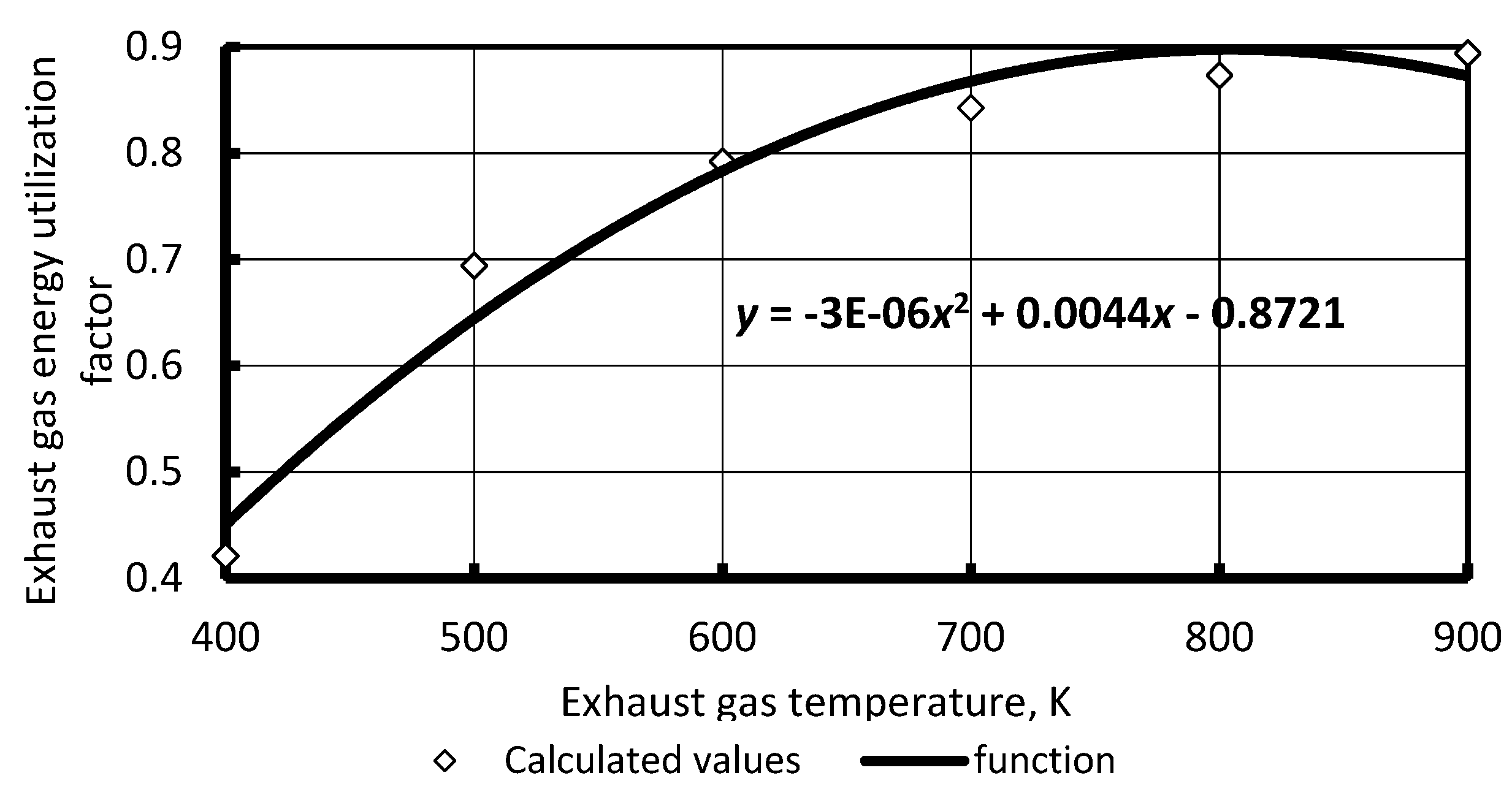
The exhaust gas energy utilization factor depends on the exhaust gas temperature at the tailpipe, ambient temperature and permissible minimum exhaust gas temperature. This is a nonlinear function (Figure 16). For this calculation we used the following temperatures: Ta = 288 K; Tb = 353 K (for diesel fuel Euro-5, S = 0.001%).
It can be seen that the energy efficiency of waste heat recovery systems depends on exhaust gas temperature. The temperature value depends on the engine load factor. Agricultural vehicles have a relatively high load, therefore, exhaust gas recovery systems are more appropriate as compared with road trucks.
4. Conclusions
Waste heat recovery systems have a huge potential for fuel consumption improvement and, therefore, pollutant emission reduction. Several bottoming technologies are under development.
Agricultural vehicles have a specific operational profile. According to our study there are currently some mature technologies for agricultural vehicles: turbocompounding, and the heating of systems. Their efficiency depends on annual utilization and fuel price. To ensure profitability of turbocompounding under the conditions of the European Union, the minimum rated power of a diesel engine is 308 kW for agricultural tractors and 388 kW for combine harvesters. Such engines are currently being manufactured.
In cold climates or during cold seasons, the heat accumulator (for start warming up) and the exhaust gases heat recovery transmission warming up systems are recommended. Heat accumulators are currently being produced. The use of waste heat recovery to heat the lubricating oil of the hydraulic clutch gearbox has high economic efficiency at low ambient temperature. For cold seasons, heating of transmission oil for the hydraulic clutch gearbox can be effective. However, these systems are not currently produced. Despite extensive research and numerous tests, this technology is not currently mature.
In hot climates or during hot seasons, especially for combine harvesters, the absorption refrigeration system is feasible. It may be a prospective technology for air-conditioning systems and intake air cooling. A coefficient of performance around 0.2 can endow economical effectiveness.
Electric turbocompounding systems are appropriate for tractors operating with electro-driven implements. They are also suitable for tractors with electromechanical or electric powertrains. However, they are currently not economically attractive.
Author Contributions
All authors analyzed the data and wrote the paper. All authors revised the article.
Funding
This research received no external funding.
Conflicts of Interest
The authors declare no conflict of interest.
References
- Goncharuk, A.G.; Havrysh, V.I.; Nitsenko, V.S. National features for alternative motor fuels market. Int. J. Energy Technol. Policy 2018, 14, 226–249. [Google Scholar] [CrossRef]
- Zhang, Q.; Pennycott, A.; Brace, C.J. A review of parallel and series turbocharging for the diesel engine. Proc. Inst. Mech. Eng. Part D J. Automob. Eng. 2013, 227, 1723–1733. [Google Scholar] [CrossRef]
- Dec, J.E. Advanced compression-ignition engines—understanding the in-cylinder processes. Proc. Combust. Inst. 2009, 32, 2727–2742. [Google Scholar] [CrossRef]
- Lion, S.; Michosa, C.N.; Vlaskosa, I.; Rouaudb, C.; Taccani, R. A review of waste heat recovery and Organic Rankine Cycles (ORC) in on-off highway vehicle Heavy Duty Diesel Engine applications. Renew. Sustain. Energy Rev. 2017, 79, 691–708. [Google Scholar] [CrossRef]
- Thiruvengadam, A.; Pradhan, S.; Thiruvengadam, P.; Besch, M.; Carder, D.; Delgado, O. Heavy-Duty Vehicle Diesel Engine. Efficiency Evaluation and Energy Audit; Final Report; Center for Alternative Fuels, Engines and Emissions, West Virginia University: Morgantown, WV, USA, 2014; p. 66. [Google Scholar]
- Borovnik, A.I.; Varfolomeeva, T.A.; Lopukh, D.G.; Golovach, V.M. Construction of Tractors and Vehicles. Part 1; BGATU: Minsk, Belarus, 2009; p. 92. [Google Scholar]
- Jadin, D.W.; Nine, R. Super Truck—Development and Demonstration a Fuel Efficiency Class 8 Tractor&Trailer. Engine Systems; DOE Contract: DE-EE0003303. DOE. MERIT REVIEW; NETL: Washington, DC, USA, 2012. [Google Scholar]
- Klanfar, M.; Korman, T.; Kujundžić, T. Fuel consumption and engine load factors of equipment in quarrying of crushed stone. Tehnički Vjesnik 2016, 23, 163–169. [Google Scholar] [CrossRef]
- Vierth, I.; Berell, H.; McDaniel, J.; Haraldsson, M.; Hammarström, U.; Yahya, M.R.; Lindberg, G.; Carlsson, A.; Ögren, M.; Björketun, U. The Effects of Long and Heavy Trucks on the Transport System; Report on a Government Assignment; Statens väg- och transportforskningsinstitut: Linköping, Sweden, 2008; p. 92. [Google Scholar]
- Lion, S.; Michos, C.N.; Vlaskos, I.; Taccani, R. A thermodynamic feasibility study of an Organic Rankine Cycle (ORC) for heavy-duty diesel engine waste heat recovery in off-highway applications. Int. J. Energy Environ. Eng. 2017, 8, 81–98. [Google Scholar] [CrossRef]
- 2018–19 Farm Machinery. Custom and Rental Rate Guide. Available online: http://publications.gov.sk.ca/documents/20/85808-2018-19%20Farm%20Machinery%20Custom%20and%20Rental%20Rate%20Guide.pdf (accessed on 1 August 2018).
- Fowler, R. Mid-Range Tractors Demonstrate Highest Annual Usage. 2015. Available online: https://intel.equipmentwatch.com/mid-range-tractors-demonstrate-highest-annual-usage/ (accessed on 10 June 2018).
- Sinha, A.K.; Shrivastava, A.K.; Gautam, A.K.; Ahamad, S. Status and utilization of tractor power in Mahakoshal Region, MP, India. Vegetos 2017, 30. [Google Scholar] [CrossRef]
- Jaber, H.; Khaled, M.; Lemenand, T.; Ramadan, M. Short review on heat recovery from exhaust gas. AIP Conf. Proc. 2016, 1758, 030045. [Google Scholar] [CrossRef]
- Teng, H.; Regner, G.; Cowland, C. Waste Heat Recovery of Heavy-Duty Diesel Engines by Organic Rankine Cycle Part I: Hybrid Energy System of Diesel and Rankine Engines. SAE Int. Publ. 2007, 1, 1–13. [Google Scholar] [CrossRef]
- Jadhao, J.S.; Thombare, D.G. Review on Exhaust Gas Heat Recovery for I.C. Engine. Int. J. Eng. Innov. Technol. (IJEIT) 2013, 2, 93–100. [Google Scholar]
- Nadaf, S.L.; Gangavati, P.B. A review on waste heat recovery and utilization from diesel engines. Int. J. Adv. Eng. Technol. 2014, 31, 39–45. [Google Scholar]
- Tractor and Combine Diesel Engines. Methods of Bench Tests. GOST 18509-88; Publishing House of Standards: Moscow, Russia, 1988; p. 54.
- Antony Greszler (Volvo Powertrain Corporation). Diesel Turbo-Compound Technology. ICCT/NESCCAF Workshop Improving the Fuel Economy of Heavy-Duty Fleets II. 20 February 2008. Available online: http://www.nescaum.org/documents/improving-the-fuel-economy-of-heavy-duty-fleets-1/greszler_volvo_session3.pdf (accessed on 15 July 2018).
- Tennant, D.W.H.; Walsham, B.E. The Turbocompound Diesel Engine. SAE Paper, No. 89064; SAE: New York, NY, USA, 1989. [Google Scholar]
- Wilson, D.E. The Design of a Low Specific Fuel Consumption Turbocompound Engine. SAE Paper, No. 860072; SAE: New York, NY, USA, 1986. [Google Scholar]
- Brands, M.C.; Werner, J.; Hoehne, J.L. Vehicle Testing of Cummins Turbocompound Diesel Engine. SAE Paper, No. 810073; SAE: New York, NY, USA, 1981. [Google Scholar]
- The Engine That Redefines Versatility. Available online: https://www.volvotrucks.us/powertrain/d13tc/ (accessed on 17 July 2018).
- Diesel Engine 6R 1500 for Agriculture and Forestry Applications with EPA Tier 4 and EU Stage IV Certification. Available online: https://mtu-online-shop.com/print/3236531_MTU_Ag_spec_6R1500.pdf (accessed on 17 October 2018).
- Detroit Diesel DD15. Available online: http://literature.puertoricosupplier.com/018/OT17636.pdf (accessed on 17 October 2018).
- Mack MP8 with Turbo Compounding Now Available for Order. Available online: https://www.macktrucks.com/community/mack-news/2017/mack-mp8-with-turbo-compounding-now-available-for-order/ (accessed on 17 October 2018).
- Hopmann, U. Diesel engine waste heat recovery utilizing electric turbocompound technology. In Proceedings of the DEER Conference, San Diego, CA, USA, 25–29 August 2002. [Google Scholar]
- Andrienko, A.A. Results of the Development and Research of a Turbofan for the Cooling System of a Turbo-Diesel Engine. Available online: http://engine.aviaport.ru/issues/59/page14.html. (accessed on 10 June 2018).
- Parimal, P.S.; Doyle, E.F. Compounding the Truck Diesel Engine with an Organic Rankine Cycle System. SAE Paper, No. 760343; SAE: New York, NY, USA, 1976. [Google Scholar]
- Hountalas, D.T.; Mavropoulos, G.C. Potential for improving HD diesel truck engine fuel consumption using exhaust heat recovery techniques. In New Trends in Technologies: Devices, Computer, Communication and Industrial Systems; Manuscript 17; InTech: London, UK, 2010; pp. 313–340. ISBN 978-953-307-212-8. [Google Scholar]
- Freymann, R.; Strobl, W.; Obieglo, A. The turbosteamer: A system introducing the principle of cogeneration in automotive application. MTZ Worldw. 2008, 69, 20–27. [Google Scholar] [CrossRef]
- Daccord, R. Cost to benefit ratio of an exhaust heat recovery system on a long haul truck. Energy Procedia 2017, 129, 740–745. [Google Scholar] [CrossRef]
- Mack Trucks Unleashes. Engine Lineup Boosting Power Productivity and Efficiency. Available online: https://www.macktrucks.com/community/mack-news/2016/mack-trucks-unleashes-2017-engine-lineup-boosting-power-productivity-and-efficiency/ (accessed on 21 June 2018).
- Volvo D13 Turbo Compound Engine Powers New Volvo VNL Series to 7.5 Percent Improvement in Fuel Efficiency. Available online: https://www.volvotrucks.us/news-and-stories/press-releases/2017/july/volvo-d13-turbo-compound-engine-powers-new-volvo-vnl-series/ (accessed on 29 June 2018).
- Teo Sheng Jye, A.; Pesiridis, A.; Rajoo, S. Effects of mechanical turbo compounding on a turbocharged diesel engine. SAE Tech. Pap. 2013. [Google Scholar] [CrossRef]
- Diesel Prices, 18-Jun-2018 (USD/l). Available online: https://www.globalpetrolprices.com/diesel_prices/ (accessed on 18 June 2018).
- Energy Efficiency and Energy Savings. The Economist Intelligence Unit Limited, 2012. Available online: http://www.gbpn.org/sites/default/files/06.EIU_CaseStudy.pdf (accessed on 19 July 2018).
- Gazzarin, C. Maschinenkosten 2016 (In German: Machinery Cost Report 2016); Agroscope Transfer Nr. 142/2016; Agroscope: Tänikon, Switzerland, 2016. [Google Scholar]
- Calcante, A.; Fontanini, L.; Mazzetto, F. Coefficients of repair and maintenance costs of self-propelled combine harvesters in Italy. Agric. Eng. Int. CIGR J. 2013, 15, 141–147. [Google Scholar]
- Benes, L.; Novak, P.; Masek, J.; Petrasek, S. John Deere combine harvesters fuel consumption and operation costs. In Proceedings of the Engineering for Rural Development, Jelgava, Latvia, 29–30 May 2014; pp. 13–17. [Google Scholar]
- Increased Profitability for Independent Power Producers. Available online: https://www.bowmanpower.com/ (accessed on 20 July 2018).
- Hoy, R.M.; Rohrer, R.; Liska, A.; Luck, J.D.; Isom, L.; Keshwani, D.R. Agricultural Industry Advanced Vehicle Technology: Benchmark Study for Reduction in Petroleum Use; Idaho National Laboratory: Idaho Falls, ID, USA, 2014; p. 64. [Google Scholar]
- John Deere 7430 E Premium. Available online: https://www.w-equipment.com/machinery-specifications/john-deere/4wd-tractors/7430-e-premium.html (accessed on 12 July 2018).
- Karner, J.; Prankl, H.; Kogler, F. Electric Drives in Agricultural Machinery. In Proceedings of the International Conference Energy, Biomass and Biological Residues. International Conference of Agricultural Engineering—CIGR-AgEng 2012: Agriculture and Engineering for a Healthier Life, Valencia, Spain, 8–12 July 2012. [Google Scholar]
- Drive Axle PowerDriveElect—Transport Concepts with Drive Axles over the Course of Time. Fliegl Agrartechnik. Available online: http://www.fliegl-agrartechnik.de/index.cfm?cid=2234&documents.id=1591 (accessed on 14 July 2018).
- Mckelkamp, M. Kinze’s 4900 Series Electric Planter, 4000 Series Row Unit and Electric Meter. 2013. Available online: http://www.agweb.com/article/kinzes_new_4900_series_planter_4000_series_row_unit_and_electric_meter/ (accessed on 14 July 2018).
- UX eSpray Trailed Sprayer. Amazone, 2010. GO for Innovation. Available online: http://info.amazone.de/DisplayInfo.aspx?id=14005 (accessed on 14 July 2018).
- Electrically-Powered Kuhn/Rauch Fertilizer Spreaders Offer Ultra-Accurate Application. Farmers Weekly, 2007. Available online: https://www.fwi.co.uk/machinery/electrically-powered-kuhn-rauch-fertiliser-spreaders-offer-ultra-accurate-application (accessed on 10 July 2018).
- Aixala, L. RENOTER Project. 3 rd Thermoelectric Applications Workshop: 20–22 March 2012 in Baltimore (MI). Available online: https://www1.eere.energy.gov/vehiclesandfuels/pdfs/thermoelectrics_app_2012/tuesday/aixala.pdf (accessed on 19 July 2018).
- Champier, D. Thermoelectric generators: A review of applications. Energy Convers. Manag. 2017, 140, 167–181. [Google Scholar] [CrossRef]
- Cherednichenko, A.K.; Tkach, M.R.; Timoshevsky, B.G.; Proskurin, A.Y. Thermochemical Heat Recovery Efficiency of the “River-Sea” Ship Power Plants. Available online: https://www.khai.edu/csp/nauchportal/Arhiv/AKTT/2016/AKTT816/Cherednichenko.pdf (accessed on 3 June 2018).
- Ibrahim, T.M.; Syahir, A.Z.; Zulkifli, N.W.M.; Masjuki, H.H.; Osman, A. Enhancing vehicle’s engine warm up using integrated mechanical approach. IOP Conf. Ser. Mater. Sci. Eng. 2017, 210, 012064. [Google Scholar] [CrossRef]
- Kauranen, P.; Heikkinen, J.; Laurikko, J.; Seppala, A. Heat and Cold Accumulator in Vehicles. Available online: https://www.motiva.fi/files/3507/Heat_and_cold_accumulators_in_vehicles.pdf (accessed on 10 July 2018).
- Heat Accumulator. Available online: http://avtomasta.ru/elektrooborudovanie/teplovoj-akkumulyator-grelka-dlya-motora.html (accessed on 20 September 2018).
- Ivannikov, A.B. Secondary Use of the Heat of the Engine Exhaust Gases to Improve the Performance of the Units by the Example of the Transmission of the Tractor; Candidate of Technical Sciences; Novosibirsk State Agrarian University: Novosibirsk, Russia, 2017. [Google Scholar]
- Lu, Y.Z.; Wang, R.Z.; Jianzhou, S.; Xu, Y.; Wu, J.Y. Practical experiments on an adsorption air conditioner powered by exhausted heat from a diesel locomotive. Appl. Therm. Eng. 2004, 24, 1051–1059. [Google Scholar] [CrossRef]
- SAE. Engine Power Test Code—Spark Ignition and Compression Ignition—Net Power Rating; SAE J 1349; Society of Automotive Engineers (SAE): New York, NY, USA, 1995. [Google Scholar]
- HİLALİ, İ.; SÖYLEMEZ, M.S. An application of engine exhaust gas driven cooling system in automobile air conditioning system. J. Therm. Sci. Technol. 2015, 35, 27–34. [Google Scholar]
- Radchenko, A.; Radchenko, M.; Konovalov, A.; Zubarev, A. Increasing electrical power output and fuel efficiency of gas engines in integrated energy system by absorption chiller scavenge air cooling on the base of monitoring data treatment. In 17th International Conference Heat Transfer and Renewable Sources of Energy (HTRSE-2018); E3S Web of Conferences: Les Ulis, France, 2018. [Google Scholar]

Figure 2.
The principle methods for exhaust gas recovery. Source: developed by authors.

Figure 3.
The relative power-turbine power as a function of rated power of an engine. Source: adapted from [27].
Figure 3.
The relative power-turbine power as a function of rated power of an engine. Source: adapted from [27].

Figure 4.
Simple payback period (PBP) for turbocompound system. Source: developed by authors.

Figure 5.
Maximum rated power (diesel fuel price—USD/L). Source: developed by authors.
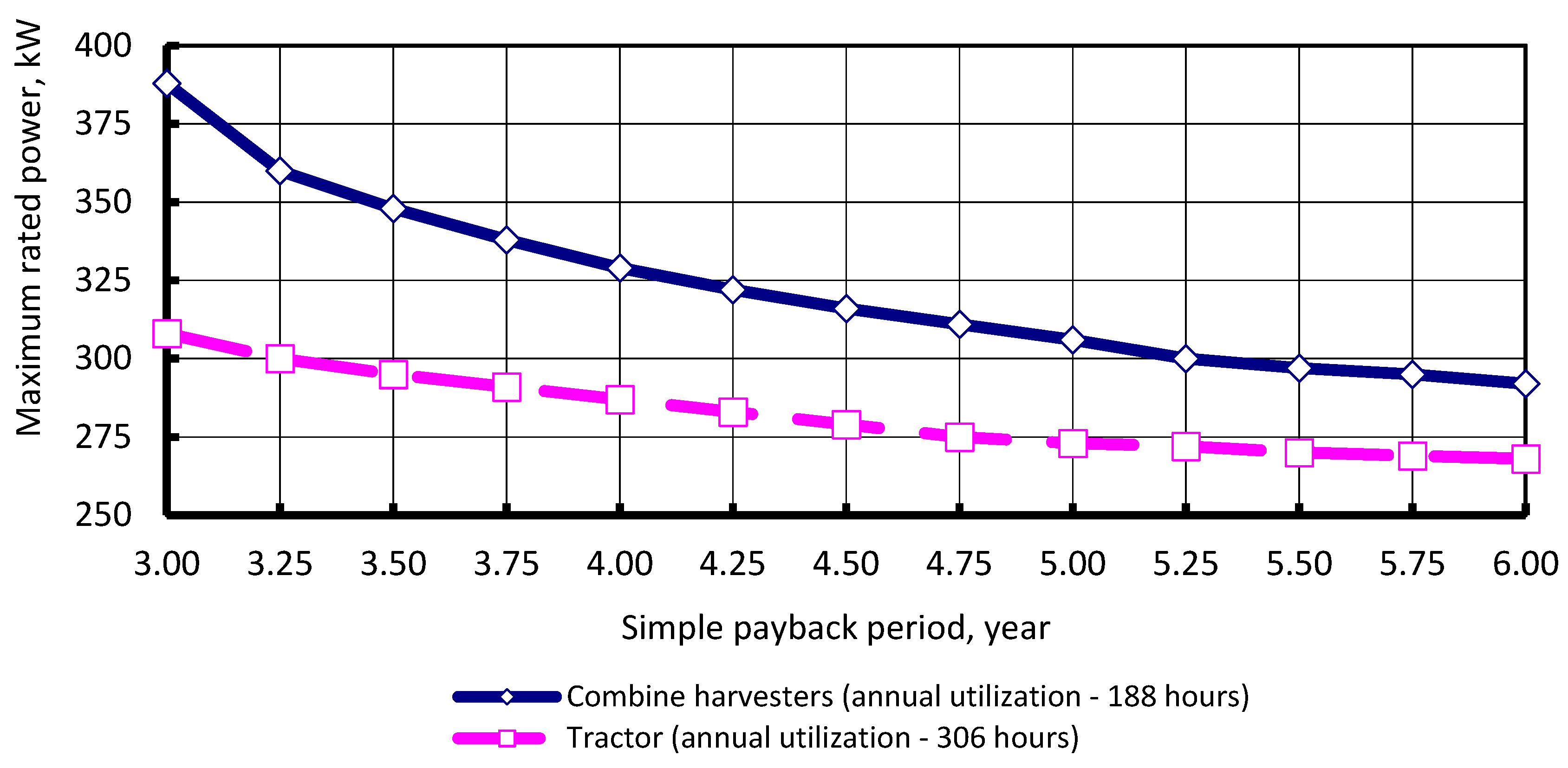
Figure 6.
Maximum rated power vs annual utilization (diesel fuel price—USD/L). Source: developed by authors.
Figure 6.
Maximum rated power vs annual utilization (diesel fuel price—USD/L). Source: developed by authors.
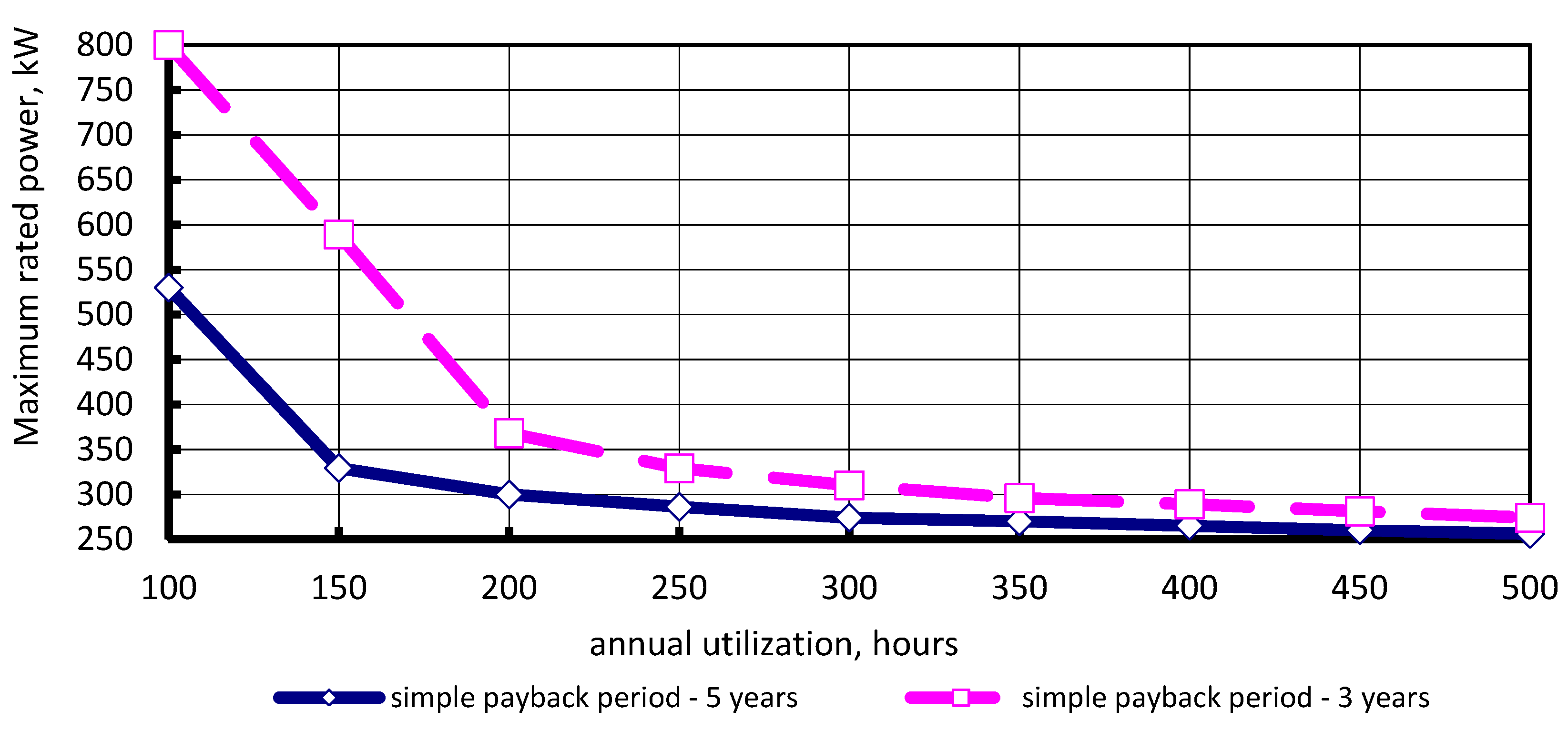
Figure 7.
The principle methods for exhaust gas recovery. Source: developed by authors.
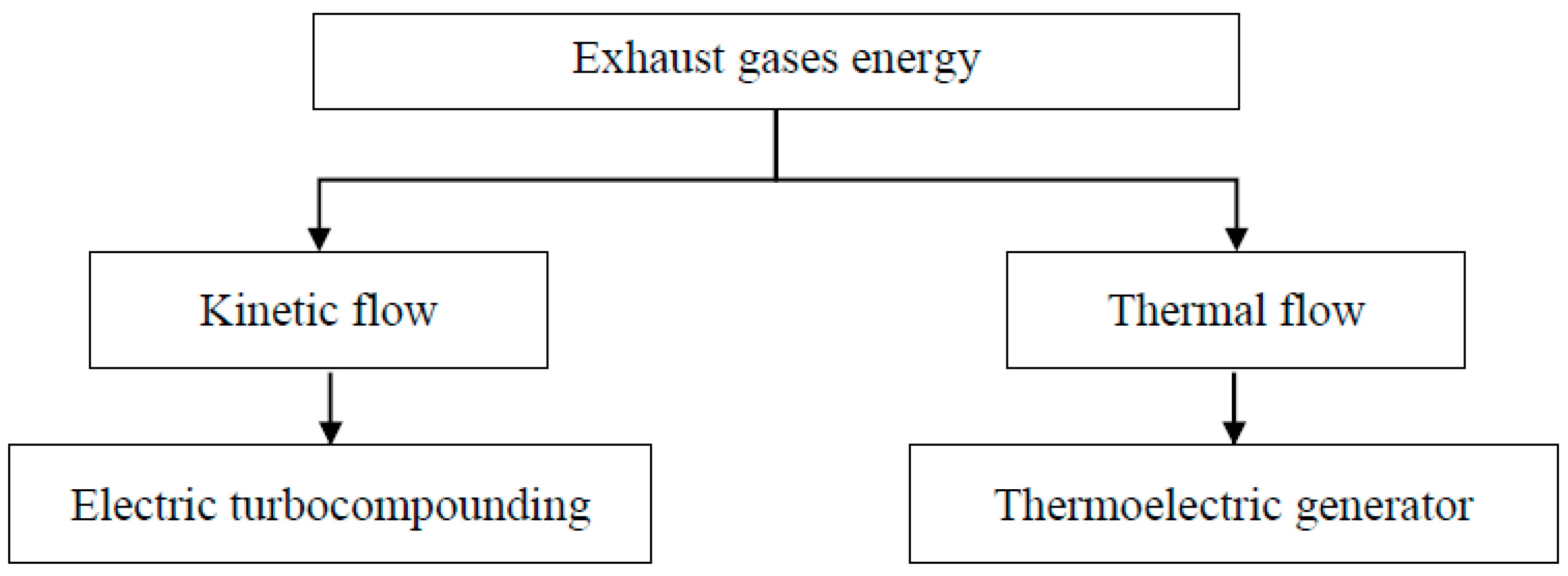
Figure 8.
Maximum electric turbocompounding system cost (simple payback period—3 years).

Figure 9.
Maximum electric turbocompounding system cost (simple payback period—5 years). Source: developed by authors.
Figure 9.
Maximum electric turbocompounding system cost (simple payback period—5 years). Source: developed by authors.

Figure 10.
Fuel cost reduction from thermoelectric generators (TEG), USD/kW. Source: developed by authors.
Figure 10.
Fuel cost reduction from thermoelectric generators (TEG), USD/kW. Source: developed by authors.

Figure 11.
Heat recovery for cooling and heating. Source: developed by authors.

Figure 12.
Power losses in the hydraulic clutch gearbox of T-150K. Source: adapted from [36].
Figure 12.
Power losses in the hydraulic clutch gearbox of T-150K. Source: adapted from [36].
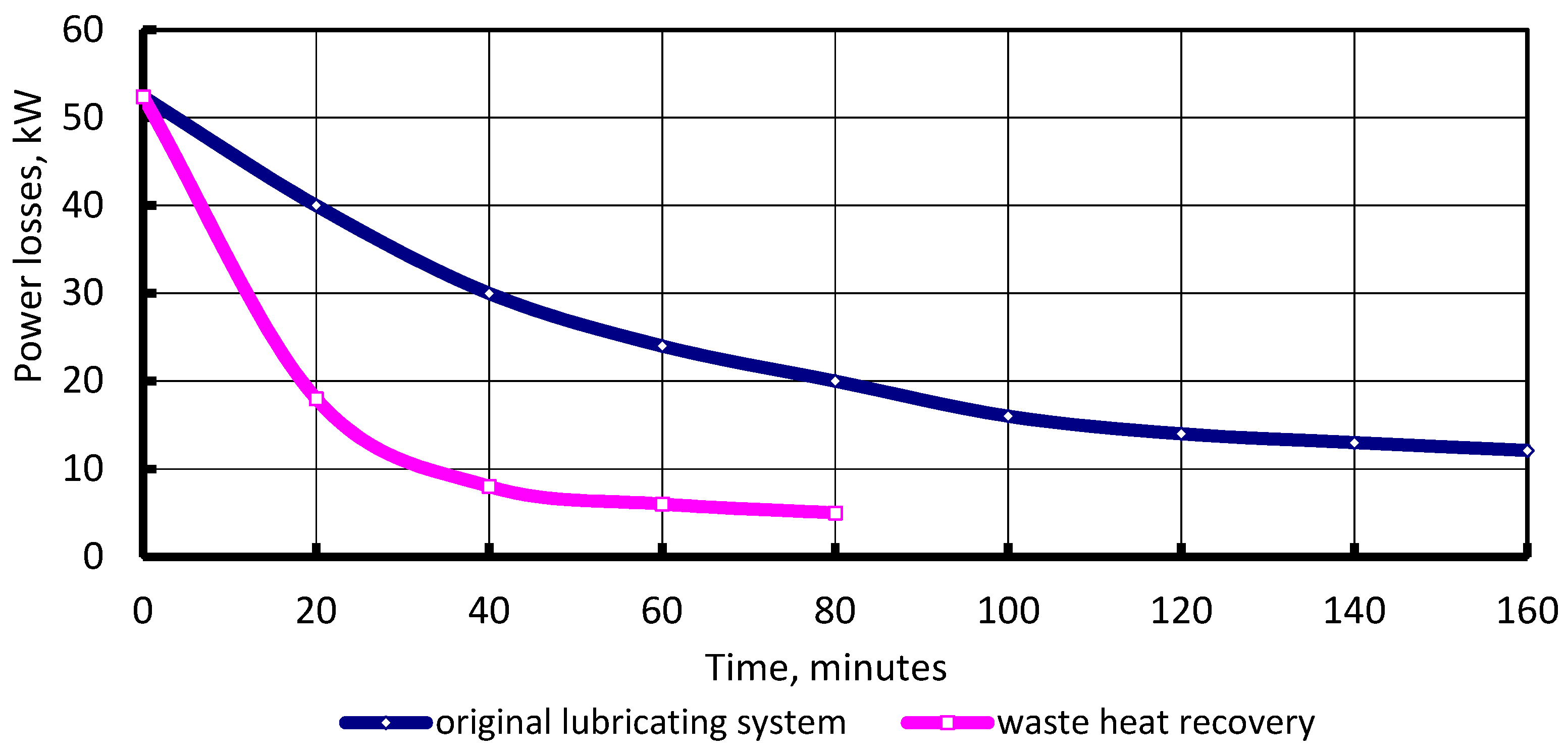
Figure 13.
Waste heat absorption refrigerator for intake air cooling: 1—evaporating air cooler; 2—condensate drain; 3—engine; 4—compressor; 5—turbine; 6—exhaust gas boiler; 7—pump; 8—working fluid condenser; 9—throttle valve; 10—ejector. Source: developed by authors.
Figure 13.
Waste heat absorption refrigerator for intake air cooling: 1—evaporating air cooler; 2—condensate drain; 3—engine; 4—compressor; 5—turbine; 6—exhaust gas boiler; 7—pump; 8—working fluid condenser; 9—throttle valve; 10—ejector. Source: developed by authors.

Figure 14.
Power and specific fuel consumption as a function of air temperature. Source: developed by authors.
Figure 14.
Power and specific fuel consumption as a function of air temperature. Source: developed by authors.

Figure 15.
Pathways for waste energy conversion. Source: developed by authors.
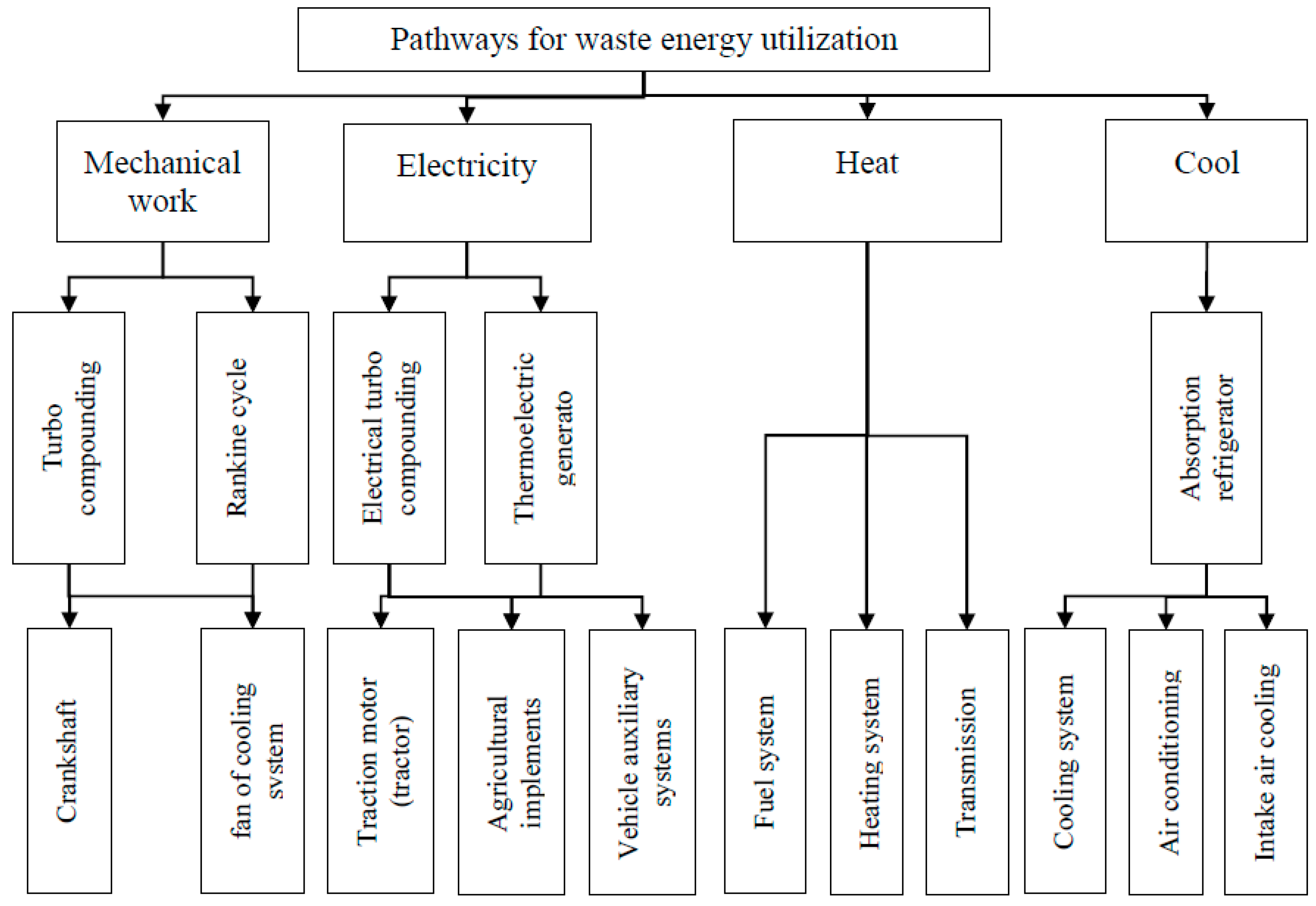
Figure 16.
Exhaust gas energy utilization factor. Source: developed by authors.

© 2018 by the authors. Licensee MDPI, Basel, Switzerland. This article is an open access article distributed under the terms and conditions of the Creative Commons Attribution (CC BY) license (http://creativecommons.org/licenses/by/4.0/).
Share and Cite
MDPI and ACS Style
Kalinichenko, A.; Havrysh, V.; Hruban, V. Heat Recovery Systems for Agricultural Vehicles: Utilization Ways and Their Efficiency. Agriculture 2018, 8, 199. https://doi.org/10.3390/agriculture8120199
AMA Style
Kalinichenko A, Havrysh V, Hruban V. Heat Recovery Systems for Agricultural Vehicles: Utilization Ways and Their Efficiency. Agriculture. 2018; 8(12):199. https://doi.org/10.3390/agriculture8120199
Chicago/Turabian StyleKalinichenko, Antonina, Valerii Havrysh, and Vasyl Hruban. 2018. "Heat Recovery Systems for Agricultural Vehicles: Utilization Ways and Their Efficiency" Agriculture 8, no. 12: 199. https://doi.org/10.3390/agriculture8120199
Note that from the first issue of 2016, this journal uses article numbers instead of page numbers. See further details here.