
Analysis of Vibration Characteristics of Podded Propulsor Shafting Based on Analytical Method

1
School of Transportation and Logistics Engineering, Wuhan University of Technology, Wuhan 430063, China
2
School of Naval Architecture, Ocean and Energy Power Engineering, Wuhan University of Technology, Wuhan 430063, China
3
National Engineering Research Centre for Water Transport Safety, Wuhan University of Technology, Wuhan 430063, China
*
Authors to whom correspondence should be addressed.
J. Mar. Sci. Eng. 2022, 10(2), 169; https://doi.org/10.3390/jmse10020169
Submission received: 27 December 2021
/
Revised: 21 January 2022
/
Accepted: 25 January 2022
/
Published: 27 January 2022
(This article belongs to the Special Issue Developments in Marine Propulsors)
Abstract
:Podded propulsors are widely used in warships and cruise ships, which have a higher requirement of vibrational and acoustic design. Therefore, studying vibration characteristics and the transmission mechanism of podded propulsor shafting is significant for reducing vibration and ensuring the safe operation of ships. This paper establishes a model of podded propulsor shafting by analytical method. The shafting is simplified to a heterogeneous variable cross-section beam, while bearings are seen as springs. The podded propulsor shafting has one radial-thrust hybrid bearing and one radial bearing. The excitations from the propeller and cabin are considered. The influences of bearing stiffness, bearing location, and excitation on vibration characteristics of shafting are analyzed. The main conclusions are as follows: Based on the analysis of the area that resonance frequency is sensitive to the change of bearing stiffness, the resonance frequencies of the shafting can be adjusted to the proper range. The large span between hybrid bearing and radial bearing leads to low stiffness of shafting and low resonances frequencies. Under radial excitations, the low vibration always occurs at the hybrid bearing, motor shafting, or propeller end of shafting. This research provides theoretical support for the design and optimization of vibration reduction of podded propulsor shafting.
1. Introduction
Pod propulsion is a marine electric propulsion system, which has been widely used in special ships such as icebreakers, warships, and cruise ships in recent years. Connecting the propeller directly to the motor, the propulsion system is made into a cabin that is integrally suspended at the stern of the ship, which can rotate 360 degrees to generate thrust in any direction [1]. Therefore, ships equipped with podded propulsors have better maneuverability. At the same time, the vibration and noise levels of ships propelled by pods have also been reduced. This is mainly due to the following reasons: The podded propulsor is arranged underwater as a whole so that the inflow is more even. Without the stern shafting, the hydrodynamic performance of the propeller is improved. Moreover, the motor is directly connected to the propeller, so there is no need to install the reduction gear [2].
In recent years, pod propulsion technology is gradually matured. Several companies have successively introduced different series of podded propulsors, such as Azimuthing Podded Drive (Azipod), Mermaid, Dolphin, Siemens Schottel Propulsor (SSP), etc. Nevertheless, with the requirements of cruise ship comfort [3] and concealment of military ships [4], many scholars have researched various performances of pod propulsion. The hydrodynamic characteristics of various types of podded propulsors under different working conditions have attracted the attention of many scholars [5,6,7,8,9,10,11]. In addition, Zhao et al. [12] predicted the self-propulsion performance of a ship model with the double L-shaped podded propulsor. Lee et al. [13] designed a fin stabilizer of podded propulsor to reduce cruise ship’s rolling motion. Ghani et al. [14] used the experimental method to study the influence of the podded propulsor on the ship’s resistance characteristics. Islam et al. [15] and Akinturk et al. [16] presented a comprehensive experimental study to measure and analyse various performances of the pod propulsion under different operating conditions, including thrust and torque of the propeller, three orthogonal forces and moments on the unit, the rotational speed of the propeller, and azimuth angle. Park et al. [17] presented a method for estimating the cabin resistance of the podded propulsor, the thrust, and torque of podded propeller blades under the influence of the cabin resistance was calculated. However, there are relatively few studies on the dynamic characteristics of the podded propulsor shafting system. The podded propulsor shafting system, although much shorter than the conventional shafting system, also has the function of transmitting the power from the propeller. It also has radial and thrust bearings to connect the propeller and cabin and transmit different vibrations with a compact form. Its reliability and dynamic characteristics affect the performance of pod propulsion and ship navigation.
Although the research on the vibration characteristics of ship propulsion shafting has been around for a long time, most of them are aimed at the shafting of conventional propulsion systems. Since Prohl improved the traditional Holzer method into the transmission matrix approach and applied it to the study of shafting vibration [18], many scholars have used this method to study vibration characteristics of marine propulsion shafting [19,20]. With the improvement of calculator computing power, the finite element method (FEM) is widely used in the analysis of shafting vibration characteristics [21,22,23]. In addition, Song et al. [24] conducted vibration modeling and experimental measurement on the propulsion shafting system, and the source of failure for the flexible rubber coupling connecting the diesel engine with the intermediate shafting was identified. Sun et al. [25] measured the transverse vibration of marine propulsion shafting system by gap-sensors, an accurate way for assessment of the natural frequency of transverse vibration was suggested.
Compared with the above numerical method and experimental method, the analytical method has the advantages of short calculation time and clear physical meaning. Some scholars also apply the analytical method to vibration analysis of marine propulsion shafting. Xu et al. [26] established an analytical model of the drive shafting, and the vibration characteristics of the shafting system under support structure deformation were investigated. In our previous work, an analytical model of shafting including propeller was established, and the vibration characteristics of the shafting system under excitation of hull’s deformation were analyzed [27].
However, in the previous work, the shafting was simplified to a homogeneous beam with a uniform cross-section. Although the shafting of the podded propulsor is shorter than the traditional diesel engine propulsion system, it has the characteristics of integrated bearing and compact internal structure. In addition, the materials and diameters of each section of the podded propulsor shafting system are quite different. Therefore, in this paper, the relevant methods are extended and applied to the research on vibration characteristics of the podded propulsor shafting system. The shafting of the podded propulsor is regarded as a heterogeneous variable cross-section beam.
Based on existing literature, this paper proposes an analytical algorithm for the vibration of the podded propulsor shafting system. The dynamic model of the podded propulsor shafting system was constructed. The continuous conditions and boundary conditions are given. When the podded propulsor was sailing, the propeller was in an uneven flow field, which generated periodic excitations to the shafting. At the same time, the cabin of the podded propulsor was excited by the pulsating pressure of the propeller and waves. This excitation from the cabin could also be transmitted to propulsion shafting through bearings. Therefore, both the excitation of the propeller and the excitation applied to the bearings are considered. The effects of bearing stiffness, bearing location, and excitations on the vibration characteristics of the podded propulsor shafting were analyzed, respectively.
2. Materials and Methods
2.1. Model of the Podded Propulsor Shafting System
As shown in Figure 1, the podded propulsor shafting system consists of the propeller, motor shafting, exciter shafting, radial bearing, and hybrid bearing composed of a radial roller bearing and a sliding thrust bearing. It can be seen from Figure 1 that the shafting of the podded propulsor is obviously different from the shafting of a traditional diesel engine propulsion system. Firstly, the pod propulsion connects the propeller directly to the driving motor, so the shafting is relatively short. After that, the diameter of the motor shafting and exciter shafting is much larger than the other shafting segments. In addition, there are also differences in materials of the shafting sections (the material of the motor shafting and the exciter shafting is silicon steel; the material of the other shafting sections is carbon steel). Therefore, the podded propulsor shafting system is regarded as a heterogeneous variable cross-section beam. In the modeling and calculation method research, the propeller is simplified to a lumped mass with the moment of inertia. The bearing is simplified to the spring structure. The propeller end of the shafting is defined as the driving end, while the other end of the shafting is defined as the non-driving end.
2.2. Motion Equations of Shafting System
In the calculation of shafting transverse vibration, the effect of shear deformation and the rotation of the section about the neutral axis is neglected. Thereby the shafting is simplified to the Euler–Bernoulli beam. When the beam vibrates transversely in the plane of symmetry, the axis of the beam has only transverse displacement . Assume that the elastic modulus and material density of the -th () section of the shafting are and , the sectional area and quadratic moment of the cross-section are and , respectively. The motion equation of transverse free vibration for podded propulsor shafting based on Euler–Bernoulli theory is specified as [28].
Separate the solution of the transverse vibration equation into variables
where denotes the modal function, and is the generalized coordinate. Substitute the above equation into Equation (1) to get
where the dot mark and the apostrophe represent the derivative with respect to time and coordinate , respectively. Set the above equation to . The parameter can represent the circular frequency. Two linear ordinary differential equations can be gained as
where the parameter is
The solution of Equation (5) determines the modal function of shafting transverse vibration. Its general solution form is
the integral constants , , and can be determined by the transverse continuous conditions and boundary conditions of the shafting.
It is assumed that each cross-section of the shafting system remains flat during the longitudinal vibration process, and the lateral deformation caused by longitudinal vibration is ignored. Set the displacement of the axis at any coordinate as . Then the longitudinal vibration dynamic equation of the shafting is
The solution of Equation (8) can be obtained by separation of variables
Substituting this equation into Equation (8) gives
Set the above equation to can get two linear ordinary differential equations
in which
The shape of shafting longitudinal vibration is determined by the solution of Equation (11), whose general form is
where the integral constant and are determined by the longitudinal boundary and continuous conditions of the shafting.
2.3. Continuity Conditions and Boundary Conditions
As shown in Figure 1, the podded propulsor shafting system is divided into several sections due to different sectional areas, materials, or the supporting role of bearings. The transverse continuity conditions between the shafting sections in terms of displacement, rotating angle, bending moment and shear force can be written as [27]
At the junction of radial bearing, the Equation (18) of continuous condition turns to
where is the radial stiffness of the bearing.
Similarly, the longitudinal continuity conditions between the shafting sections in terms of displacement and force can be written as
When the thrust bearing is considered, Equation (21) becomes
where is the axial stiffness of the thrust bearing.
The boundary conditions of transverse vibration of the shafting are established in this part. The non-driving end of the podded propulsor is regarded as the free boundary. That is, the bending moment and shear force are equal to zero as follows:
At the driving end of the shafting, the propeller can be regarded as a lumped mass with the moment of inertia. The translational and rotary inertial force components caused by the propeller are
Therefore, the transverse boundary conditions of the driving end of the shafting can be expressed as
where is the moment of inertia, is the total mass of the propeller considering the entrained water effect. The entrained water mass of the propeller can be expressed as
where is the mass of the propeller, is the number of propeller blades, and is the pitch ratio. is a parameter determined by the propeller disc area ratio
Similarly, longitudinal vibration boundary conditions of the driving end and the non-driving end can be established as:
2.4. Force Excitation
The main excitation of the podded propulsor shafting system is from propeller running and the force of the cabin. The Dirac function is used to express the excitation of the shafting at the bearing and propeller as:
where is the amplitude of the excitation force, is the coordinate of the excitation position.
Since the excitation from the propeller and waves applied to the cabin is mainly transmitted to the shafting through radial bearings, only the radial excitation on the bearing is considered. This excitation applied to the bearing can be added to the shear continuity condition of transverse vibration. Thus, Equation (19) becomes
In addition, propeller excitation can be added to the transverse and longitudinal boundary conditions as
3. Results and Discussion
3.1. Calculation Model
In this paper, a certain type of podded propulsor shafting system is used as the calculation model. The shafting system is divided into seven sections, and the diameter and location of each section are shown in Figure 2. The material of the motor shafting and the exciter shafting is silicon steel with the density of 7800 kg/m3 and elastic modulus of . The material of the other shafting sections is carbon steel, whose density and elastic modulus are 7833.41 kg/m3 and , respectively. A radial roller bearing is arranged on the driving end of the podded propulsor shafting system. A hybrid bearing, which includes a radial roller bearing and a sliding thrust bearing, is arranged on the non-driving end. The stiffness of the radial bearing is . The radial stiffness and axial stiffness of the hybrid bearing are and , respectively. The total mass of the propeller considering the entrained water effect is 30,072.8 kg, and the moment of inertia is 121,838 kg·m2. Take the axle center of the podded propulsor shafting system when it is not deformed as the axis, the direction perpendicular to the axis as the axis to establish a coordinate system. The radial () and axial () excitations of the propeller and the radial excitations (, ) transmitted to the shafting through the bearing are considered. The amplitudes of all excitations are 1 N.
3.2. Method Verification
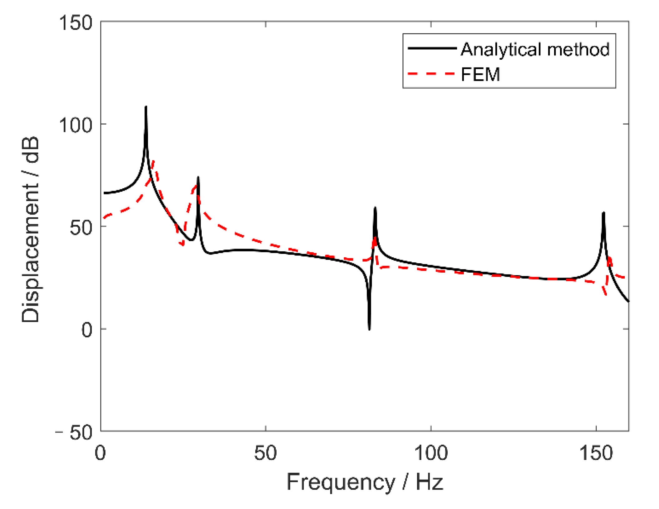
In order to verify the correctness of the analytical method used in this paper, the shafting model of the podded propulsor is established by finite element software ANSYS Workbench®. The bearing is simulated by COMBIN14 elements, and the lower end is set to be fully constrained; that is, the bearing and the cabin are regarded as a rigid connection. The MASS21 elements were added to the driving end of the shafting to simulate the moment of inertia and mass of the propeller. Radial unit forces , and are applied at the same time. The transverse vibration response at is taken and compared with the analytical method. It can be seen from Figure 3 that the vibration response trend of the analytical method and FEM are basically same. The resonance frequencies and amplitudes gained from the analytical method have a certain deviation from the FEM. This is mainly due to the Euler–Bernoulli beam theory, which is the basis of the analysis method, only considers bending deformation in the transverse vibration analysis. In addition, the division and density of mesh in the FEM also have an influence on the calculation results. In general, the comparison results of the two methods are within an acceptable range. It shows that the analytical method used in this paper is correct to establish the podded propulsor shafting model and perform vibration analysis.
3.3. Influence of Bearing Stiffness on Vibration Characteristics
The impact of bearing stiffness on vibration characteristics of the podded propulsor shafting system is investigated in this section. The frequency response of the podded propulsor shafting under different radial stiffness of bearings are compared in Figure 4. Here the stiffnesses of the two radial bearings are considered to be equal, and the radial excitations are set at the propeller () and bearings (, ) for the analysis of transverse vibration. It can be seen from Figure 4, the resonance frequency of each order increases as the radial stiffness of bearings increases. Moreover, there is a sensitive area where the growth of each order resonance frequency is significantly rapid with the increase of the bearing stiffness. Taking the second-order resonance as an example, when bearing radial stiffness is less than , the resonance frequency increases very slowly, indicating that the stiffness is small and the supporting effect of the bearings on the shafting system is weak. When the bearing stiffness is between and , the resonance frequency has greater sensitivity to the change of bearings radial stiffness. When the radial stiffness of bearings is greater than , the influence of radial stiffness on resonance frequency becomes negligible, where it can be considered as a rigid support area.
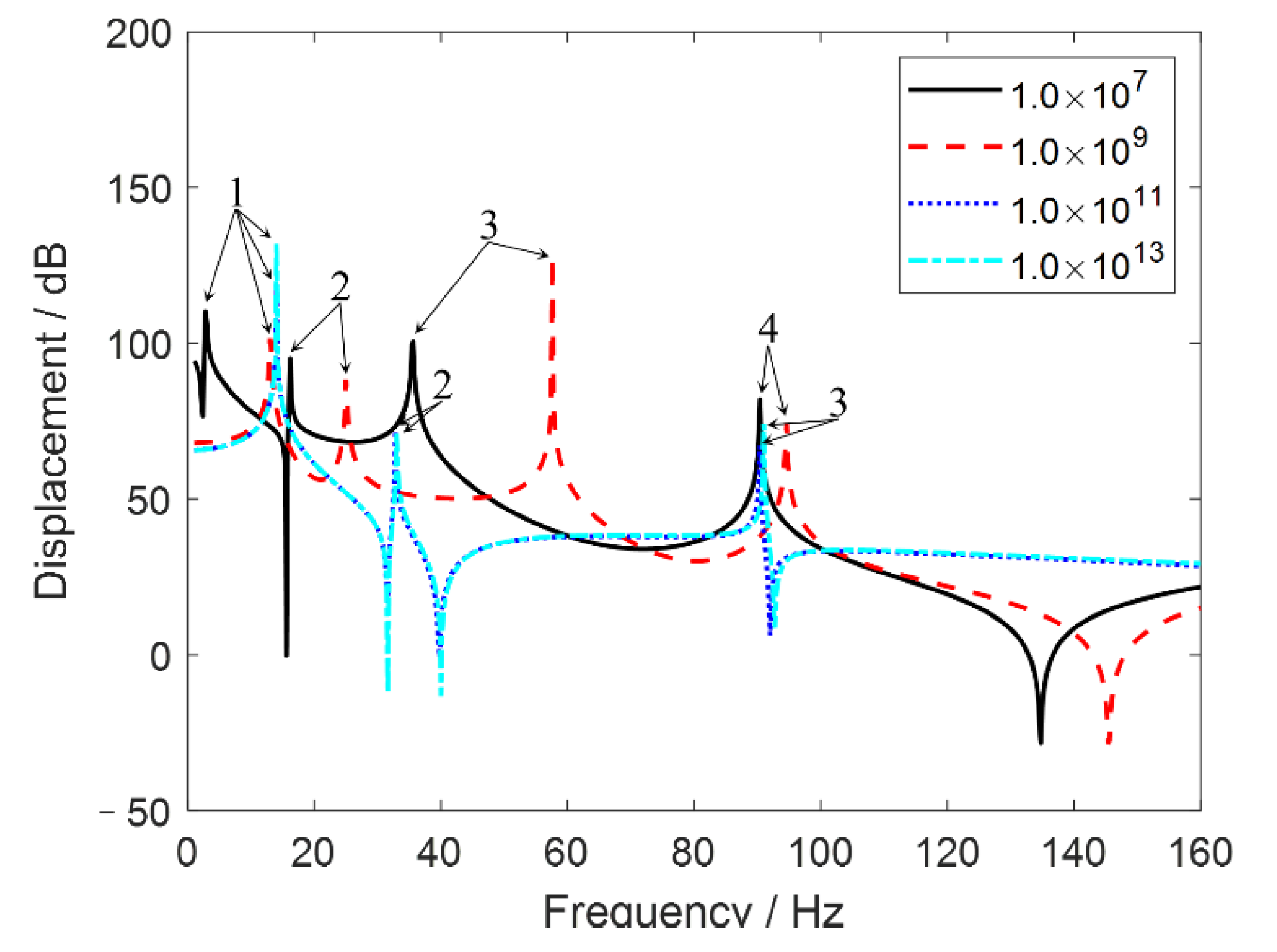
In order to make it clear, the vibration response curves of the shafting system under four different radial stiffnesses are shown in Figure 5. When bearings stiffnesses are , and , the first-order resonance frequencies are similar. This is because these three stiffness values have crossed the “sensitive area” of first-order resonance. Meanwhile, it can be observed that the two vibration response curves with stiffness and coincide. It means that when the stiffness of bearings is higher than that in the “sensitive area”, bearings can be considered as rigid supports.
The influence of axial stiffness of hybrid bearing on longitudinal vibration is presented in Figure 6, where the axial excitation on the propeller () is considered. Similar to the transverse vibration, there is also an area in the longitudinal vibration where the resonance frequency has greater sensitivity to the bearing stiffness. However, it is shown that the first resonance frequency goes from 3 Hz to 143 Hz within the axial stiffness changing from to , which indicates that the resonance frequencies of longitudinal vibration change more sharply under different axial bearing stiffnesses than that of transverse vibration.
It can be seen from Figure 4 and Figure 6 that when the stiffness of the bearing is relatively small, the resonance frequencies of the transverse and longitudinal vibrations fall into the range of the wave frequency and the propeller blade frequency, which leads to the easy occurrence of resonance and threatens the safety of the shafting. Where the main energy of sea waves is in the frequency range below 10 Hz [29], the propeller blade frequency is determined by the number of revolutions per second of the shafting and the number of propeller blades , . In addition, the stiffness of the bearing cannot be selected too large to avoid shafting and the cabin tend to rigid connection, resulting in excitation on the cabin being more easily transmitted to the shafting through bearings, thus aggravating shafting vibration. Therefore, in the design stage of the podded propulsor, the stiffness of the bearing can be adjusted in the sensitive area to avoid resonance and reduce vibration of the shafting.
Furthermore, it can also be concluded by comparing these two forms of vibration that the longitudinal vibration has less resonance in the low-frequency range than transverse vibration. That is, the transverse vibration of the podded propulsor shafting is more obvious in the low-frequency range.
3.4. Influence of Bearing Locations on Vibration Characteristics
In the dynamic model of the podded propulsor shafting established in this paper, the change of the radial bearing position mainly affects the transverse vibration of the shafting. So only the transverse vibration characteristics of the podded propulsor shafting under different bearing locations are analyzed in the present section. Unit radial forces are applied simultaneously at the propeller () and bearings (, ).
The transverse vibration of the podded propulsor shafting with hybrid bearing at different locations is shown in Figure 7. When the location of the hybrid bearing is close to the non-driving end of the podded propulsor shafting system (, as shown in Figure 2), the frequencies of the first two order resonance decreases. This is mainly because the main mass of the podded propulsor shafting system is concentrated on the motor shafting between the hybrid bearing and the radial bearing. As the hybrid bearing approaches the non-driving end of the shafting, the span between the hybrid bearing and radial bearing becomes large, which causes the stiffness of the podded propulsor shafting to decrease. Thereby the first two resonances move to the lower frequencies. The change of the radial bearing position has a similar effect on the transverse vibration characteristics of the podded propulsor shafting, as seen in Figure 8. When the location of the radial bearing gradually approaches the driving end of the podded propulsor shafting (, as shown in Figure 2), the frequencies of each resonant peak get small. In a word, when bearings of the podded propulsor are close to the end of the shafting, the frequency of the first few transverse resonances may reduce to the range of the propeller blade frequency, which may cause resonance and seriously affect the safety of the shafting operation.
3.5. Influence of Excitation Location on Vibration Characteristics
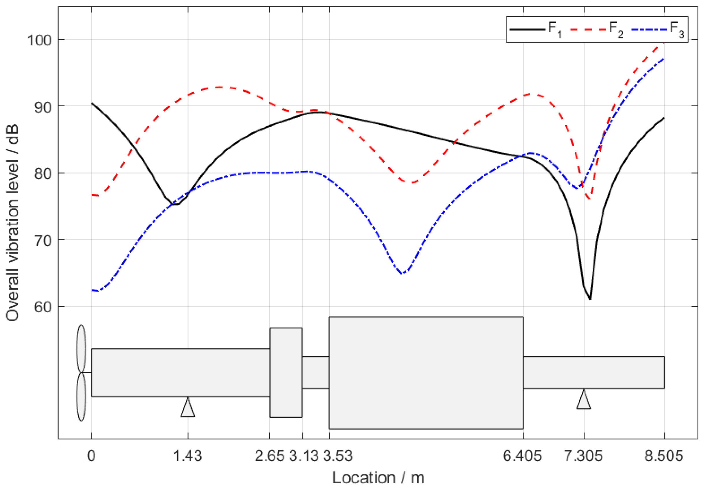
Among the considered four excitations, as shown in Figure 2, , and are all radial excitations, set on the propeller, radial bearing, and hybrid bearing, respectively. Thus, the influence of the excitation location on the transverse vibration characteristics of the podded propulsor shafting system is analyzed in this section. All three excitations are considered as unit forces. In order to compare the vibration level of the entire shafting under different excitations more intuitively, the vibration is described as
where is the vibration displacement amplitude of each corresponding frequency. is the reference value, for displacement .
It can be seen from Figure 9 that the vibration response curve under excitation of propeller () has the lowest vibration at the hybrid bearing. This is mainly due to the hybrid bearing being far from the excitation and having high stiffness. When the excitation is applied to the radial bearing (), there is also a low vibration near the hybrid bearing. In addition, the vibration response of is low at the driving end of the shafting system and the motor shafting part. The low vibration at the driving end of the shafting is due to the suppression of vibration by the inertial resistance of the propeller. The reason for the low vibration of the motor shafting is that the large diameter has greater stiffness and mass, resulting in a strong ability to resist deformation. For the case under excitation at hybrid bearing (), similarly to the case for , the low vibration occurs at the hybrid bearing, motor shafting, and driving end of the shafting. However, since is applied to the hybrid bearing, the vibration response drops relatively small near the hybrid bearing.
4. Conclusions
An analytical algorithm for treating the podded propulsor shafting system as a non-homogeneous variable-section beam is proposed in this paper. Continuity conditions are established between the segments of the shafting system. Boundary conditions are given for the propeller end and the free end, respectively. The vibration characteristics of the podded propulsor shafting system under excitation of propeller and excitation transmitted through bearings are analyzed. The main conclusions are as follows:
- There is an area where resonance frequencies of shafting are very sensitive to the change of bearings stiffness. According to this analysis, the resonance frequencies of the shafting system can be adjusted to the proper range by changing the bearing stiffness in the sensitive area.
- Since the axial stiffness of the podded propulsor shafting system is relatively large, the longitudinal vibration has less resonance peaks in the low-frequency range than transverse vibration. Thus, the transverse vibration of the shafting system is more obvious than the longitudinal vibration in the low-frequency range.
- When the span of the bearing supports increase, the stiffness of the shafting and the frequencies of low-order transverse resonance decrease. As a result, the frequency of the first few transverse resonances may reduce to the range of the propeller blade frequency, which seriously endangers the operating safety of the podded propulsor.
- Under the radial excitations, the low vibration always occurs at the hybrid bearing, motor shafting, or propeller end. For the case under excitation of propeller (), the lowest vibration is at the hybrid bearing, as it is far from the excitation and has high stiffness. However, for the case under excitation at hybrid bearing (), the lowest vibration occurs at the propeller end (due to the propeller mass) and the motor shafting (due to its great mass and stiffness). For the case under excitation at radial bearing (), as the excitation is at the middle part, all these three parts have similar low vibrations.
Author Contributions
Conceptualization, C.Z. and Y.T.; methodology, C.Z.; software, Y.T.; validation, C.Z. and Y.T.; formal analysis, C.Z.; investigation, W.O.; resources, C.Z.; data curation, C.Z.; writing—original draft preparation, Y.T. and C.Z.; writing—review and editing, Y.T., C.Z. and L.Y.; visualization, L.Y.; supervision, X.Z.; project administration, C.Z.; funding acquisition, C.Z. All authors have read and agreed to the published version of the manuscript.
Funding
This research was funded by the High-tech Ship Project of the Ministry of Industry and Information Technology of the People’s Republic of China.
Institutional Review Board Statement
Not applicable.
Informed Consent Statement
Not applicable.
Data Availability Statement
Not applicable.
Conflicts of Interest
The authors declare no conflict of interest.
References
- Islam, M.F. Modeling techniques of puller podded propulsor in extreme conditions. J. Ship Res. 2017, 61, 230–255. [Google Scholar] [CrossRef]
- Pakaste, R.; Laukia, K.; Wilhelmson, M.J. Azipod propulsion systems for marine vessels. Electro-Technology 2000, 3, 40–43. [Google Scholar]
- Goujard, B.; Sakout, A.; Valeau, V. Acoustic comfort on board ships: An evaluation based on a questionnaire. Appl. Acoust. 2005, 66, 1063–1073. [Google Scholar] [CrossRef]
- Ebrahimi, A.; Razaghian, A.H.; Seif, M.; Zahedi, F.; Nouri-Borujerdi, A. A comprehensive study on noise reduction methods of marine propellers and design procedures. Appl. Acoust. 2019, 150, 55–60. [Google Scholar] [CrossRef]
- Wang, W.; Zhao, D.; Guo, C.Y.; Pang, Y.J. Analysis of Hydrodynamic Performance of L-Type Podded Propulsion with Oblique Flow Angle. J. Mar. Sci. Eng. 2019, 7, 51. [Google Scholar] [CrossRef] [Green Version]
- Reza, S.; Hassan, G. Numerical investigation of yaw angle effects on propulsive characteristics of podded propulsors. Int. J. Nav. Arch. Ocean 2013, 5, 287–301. [Google Scholar]
- Shamsi, R.; Ghassemi, H. Hydrodynamic analysis of puller and pusher of azimuthing podded drive at various yaw angles. Proc. Inst. Mech. Eng. Part M J. Eng. Marit. Environ. 2014, 228, 55–69. [Google Scholar] [CrossRef]
- Shamsi, R.; Ghassemi, H.; Molyneux, D.; Liu, P. Numerical hydrodynamic evaluation of propeller (with hub taper) and podded drive in azimuthing conditions. Ocean Eng. 2014, 76, 121–135. [Google Scholar] [CrossRef]
- Kyu, C.J.; Gil, P.H.; Tae, K.H. A numerical study of scale effects on performance of a tractor type podded propeller. Int. J. Nav. Arch. Ocean 2014, 6, 380–391. [Google Scholar]
- Hu, J.; Zhao, W.; Chen, C.G.; Cuo, C.Y. Numerical simulation on the hydrodynamic performance of an azimuthing pushing podded propulsor in reverse flow and rotation. Appl. Ocean Res. 2020, 104, 102338. [Google Scholar] [CrossRef]
- Zhao, D.; Guo, C.; Wu, T.; Wang, W.; Yin, X. Hydrodynamic Interactions between Bracket and Propeller of Podded Propulsor Based on Particle Image Velocimetry Test. Water 2019, 11, 1142. [Google Scholar] [CrossRef] [Green Version]
- Zhao, D.; Guo, C.; Lin, J. Prediction of Self-Propulsion Performance of Ship Model with Double L-Type Podded Propulsors and Conversion Method for Full-Scale Ship. J. Mar. Sci. Eng. 2019, 7, 162. [Google Scholar] [CrossRef] [Green Version]
- Lee, S.; Rhee, K.P.; Choi, J.W. Design of the roll stabilization controller, using fin stabilizers and pod propellers. Appl. Ocean Res. 2011, 33, 229–239. [Google Scholar] [CrossRef]
- Ghani, M.P.; Yaakob, O.; Ismail, N.; Kader, A.S.; Sabki, A.F.; Singaraveloo, P. Experimental analysis of podded propulsor on naval vessel. TransNav Int. J. Mar. Navig. Saf. Od Sea Transp. 2014, 8, 239–242. [Google Scholar]
- Islam, M.F.; Veitch, B.; Akinturk, A.; Bose, N.; Liu, P. Performance study of podded propulsor in static azimuthing conditions. Int. Shipbuild. Prog. 2009, 56, 135–157. [Google Scholar]
- Akinturk, A.; Islam, M.F.; Veitch, B.; Liu, P. Performance of dynamic azimuthing podded propulsor. Int. Shipbuild. Prog. 2012, 59, 83–106. [Google Scholar]
- Park, H.G.; Choi, J.K.; Kim, H.T. An estimation method of full scale performance for pulling type podded propellers. Int. J. Nav. Arch. Ocean 2015, 6, 965–980. [Google Scholar] [CrossRef] [Green Version]
- Prohl, M. A method for calculating vibration frequency and stress of a banded group of turbine buckets. Trans. ASME 1958, 80, 169. [Google Scholar] [CrossRef]
- Li, C.; Huang, X.; Hua, H. Dynamic modeling and analysis of axial vibration of a coupled propeller and shafting system. J. Mech. Sci. Technol. 2016, 30, 2953–2960. [Google Scholar] [CrossRef]
- Dylejko, P.G.; Kessissoglou, N.J.; Yan, T.; Norwood, C.J. Optimisation of a resonance changer to minimise the vibration transmission in marine vessels. J. Sound Vib. 2007, 300, 101–116. [Google Scholar] [CrossRef]
- Abdul, H.A.; Khalaf, A.J. Study of effective parameters in stability and vibration of marine propulsion shafting systems. J. Phys. Conf. Ser. 2021, 1973, 012032. [Google Scholar]
- Zou, D.; Zhang, J.; Ta, N.; Rao, Z. Study on the axial exciting force characteristics of marine propellers considered the effect of the shafting and blade elasticity. Appl. Ocean Res. 2019, 89, 141–153. [Google Scholar] [CrossRef]
- Huang, Q.; Zhang, C.; Jin, Y.; Yuan, C.; Yan, X. Vibration analysis of marine propulsion shafting by the coupled finite element method. J. Vibroeng. 2015, 17, 3392–3403. [Google Scholar]
- Song, M.H.; Nam, T.K.; Lee, J. Self-excited torsional vibration in the flexible coupling of a marine propulsion shafting system employing cardan shaftings. J. Mar. Sci. Eng. 2020, 8, 348. [Google Scholar] [CrossRef]
- Sun, J.S.; Han, T.M.; Lee, K.K.; Kim, U.K. A study on the measurement and analysis of whirling vibration behavior of marine propulsion shafting system using gap-sensors. J. Korean Soc. Mar. Eng. 2015, 39, 130–135. [Google Scholar] [CrossRef]
- Xu, X.T.; Yang, R.; Wang, C.X.; Chen, L.J. Analysis on the Effect of Support Structure Deformation on the Vibration Characteristics of Drive Shaft. In Proceedings of the INTER—NOISE and NOISE—CON Congress and Conference Proceedings, Madrid, Spain, 30 September 2019; Institute of Noise Control Engineering: Reston, VA, USA, 2019. [Google Scholar]
- Zhang, C.; Tian, Z.; Yan, X. Analytical analysis of the vibration of propulsion shafting under hull deformation excitations. J. Vibroeng. 2016, 18, 44–55. [Google Scholar]
- Clough, R.W.; Penzien, J.; Griffin, D.S. Dynamics of Structures; Computers and Structures: New York, NY, USA, 1995; pp. 377–395. [Google Scholar]
- Xing, J.T.; Tian, Z.; Yan, X.P. The dynamics of ship propulsion unit-large hull–water interactions. Ocean Eng. 2016, 124, 349–362. [Google Scholar] [CrossRef] [Green Version]
Figure 1.
Schematic diagram of podded propulsor shafting system.
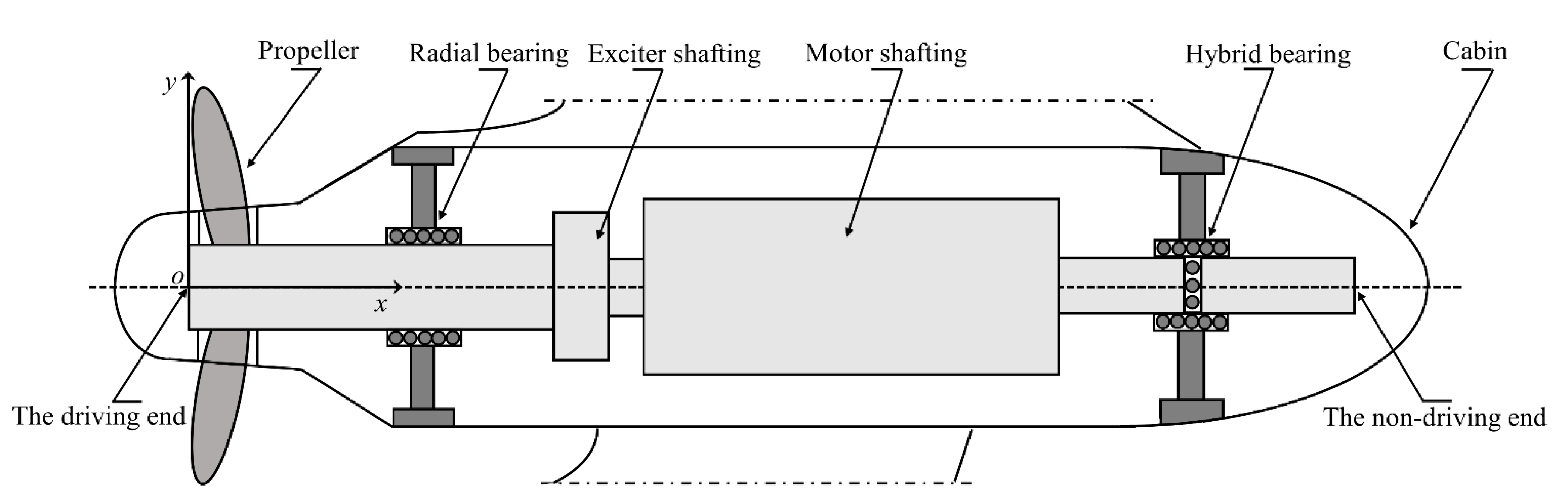
Figure 2.
Schematic diagram of the calculation model. The unit of location and diameter is .
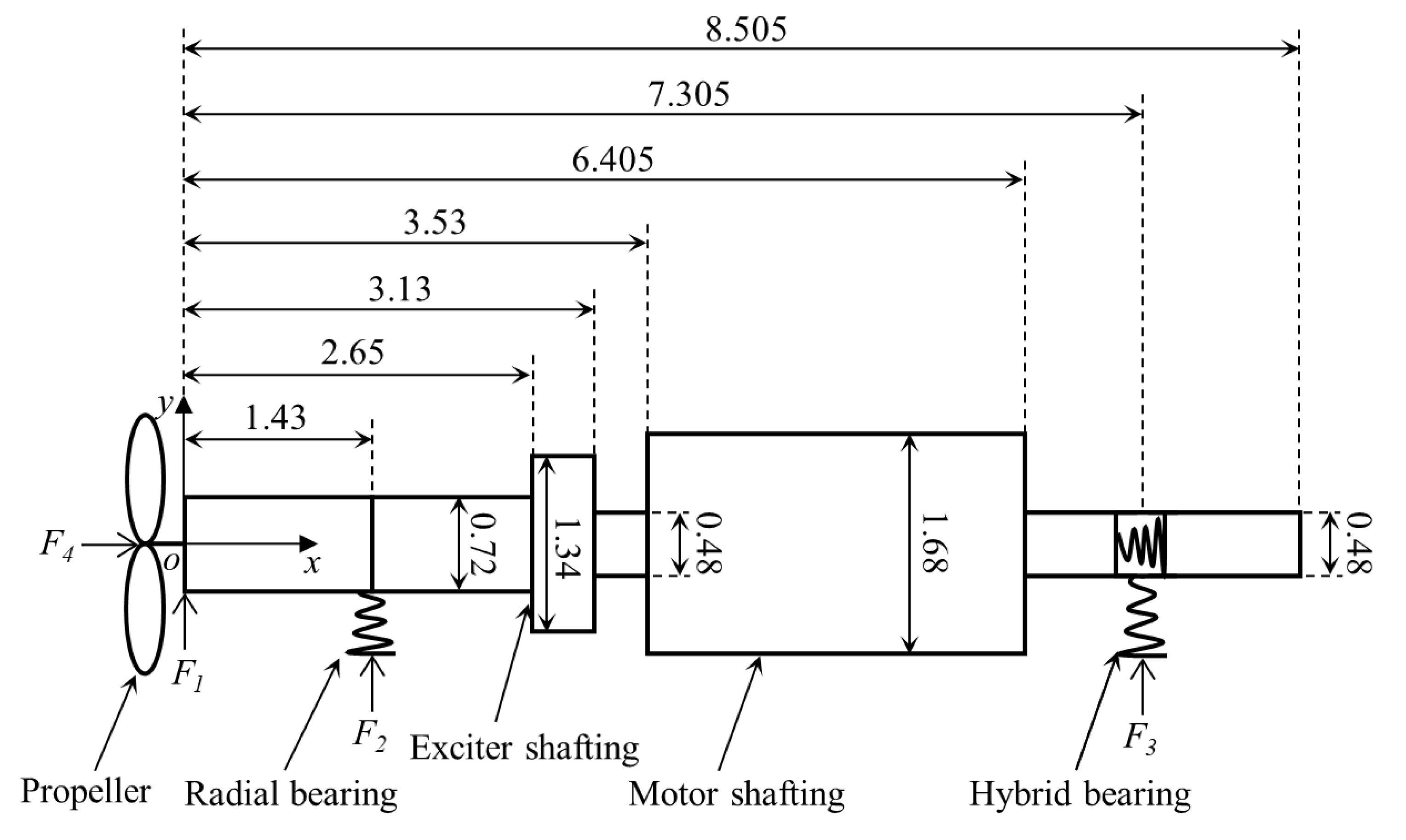
Figure 3.
Comparison of vibration response between analytical method and the FEM. The location of the response point is .
Figure 3.
Comparison of vibration response between analytical method and the FEM. The location of the response point is .

Figure 4.
Transverse vibration response under different bearings stiffness and frequency. (a,b) are the vibration response at . (b) is the top view. Numbers and arrows are used to mark the order of the resonance.
Figure 4.
Transverse vibration response under different bearings stiffness and frequency. (a,b) are the vibration response at . (b) is the top view. Numbers and arrows are used to mark the order of the resonance.
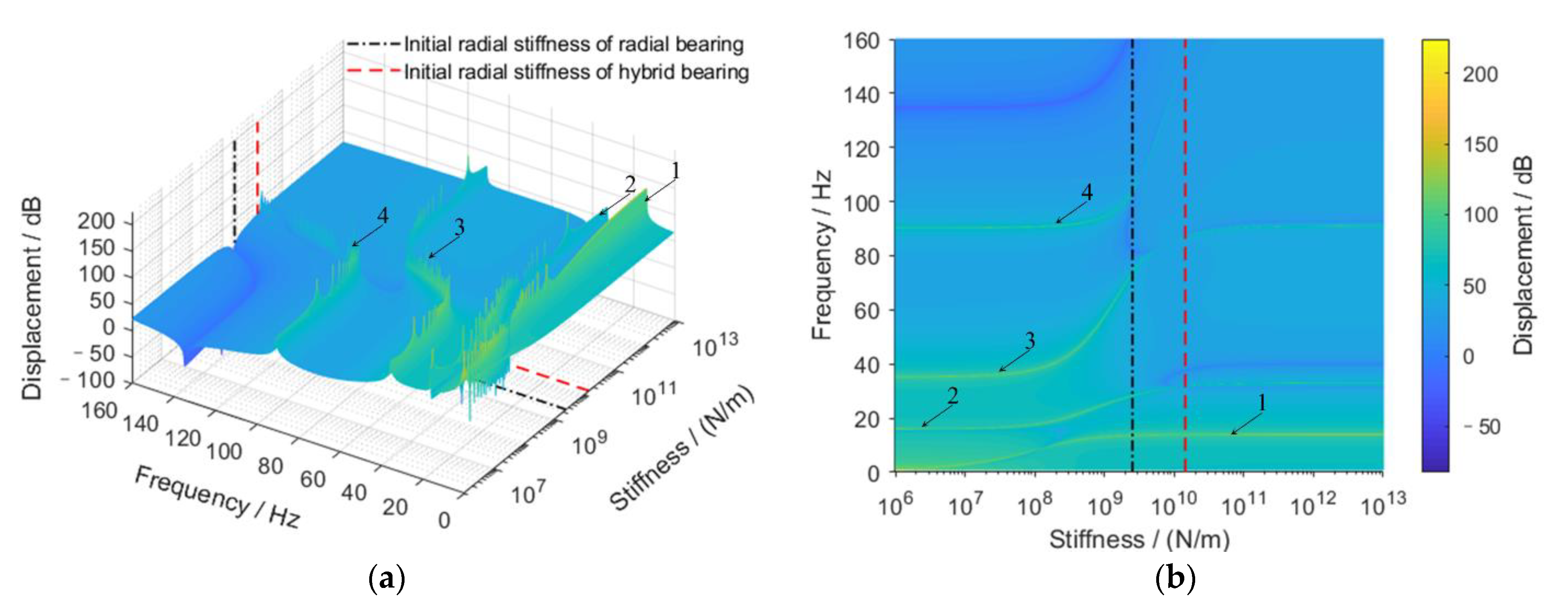
Figure 5.
Transverse vibration response under different bearings stiffness. The location of the response point is . Numbers and arrows are used to mark the order of the resonance.
Figure 5.
Transverse vibration response under different bearings stiffness. The location of the response point is . Numbers and arrows are used to mark the order of the resonance.

Figure 6.
Longitudinal vibration response under different bearings stiffness and frequency. (a,b) are the vibration response at . (b) is the top view. Numbers and arrows are used to mark the order of the resonance.
Figure 6.
Longitudinal vibration response under different bearings stiffness and frequency. (a,b) are the vibration response at . (b) is the top view. Numbers and arrows are used to mark the order of the resonance.

Figure 7.
Transverse vibration under different hybrid bearing locations. (a,b) are the vibration response at . (b) is the top view. Numbers and arrows are used to mark the order of the resonance.
Figure 7.
Transverse vibration under different hybrid bearing locations. (a,b) are the vibration response at . (b) is the top view. Numbers and arrows are used to mark the order of the resonance.

Figure 8.
Transverse vibration under different radial bearing stiffness. (a,b) are the vibration response at . (b) is the top view. Numbers and arrows are used to mark the order of the resonance.
Figure 8.
Transverse vibration under different radial bearing stiffness. (a,b) are the vibration response at . (b) is the top view. Numbers and arrows are used to mark the order of the resonance.

Figure 9.
Transverse vibration response of podded propulsor shafting system under different radial excitation point positions. The calculation range of the overall vibration level is 0–160 Hz.
Figure 9.
Transverse vibration response of podded propulsor shafting system under different radial excitation point positions. The calculation range of the overall vibration level is 0–160 Hz.

Publisher’s Note: MDPI stays neutral with regard to jurisdictional claims in published maps and institutional affiliations. |
© 2022 by the authors. Licensee MDPI, Basel, Switzerland. This article is an open access article distributed under the terms and conditions of the Creative Commons Attribution (CC BY) license (https://creativecommons.org/licenses/by/4.0/).
Share and Cite
MDPI and ACS Style
Tian, Y.; Zhang, C.; Yang, L.; Ouyang, W.; Zhou, X. Analysis of Vibration Characteristics of Podded Propulsor Shafting Based on Analytical Method. J. Mar. Sci. Eng. 2022, 10, 169. https://doi.org/10.3390/jmse10020169
AMA Style
Tian Y, Zhang C, Yang L, Ouyang W, Zhou X. Analysis of Vibration Characteristics of Podded Propulsor Shafting Based on Analytical Method. Journal of Marine Science and Engineering. 2022; 10(2):169. https://doi.org/10.3390/jmse10020169
Chicago/Turabian StyleTian, Yaqi, Cong Zhang, Lei Yang, Wu Ouyang, and Xincong Zhou. 2022. "Analysis of Vibration Characteristics of Podded Propulsor Shafting Based on Analytical Method" Journal of Marine Science and Engineering 10, no. 2: 169. https://doi.org/10.3390/jmse10020169
Note that from the first issue of 2016, this journal uses article numbers instead of page numbers. See further details here.