Article

Techno-Economic Evaluation of Direct Low-Pressure Selective Catalytic Reduction for Boil-Off Gas Treatment Systems of NH3-Fueled Ships

1
Department of Mechanical Convergence Engineering, Gyeongsang National University, 54, Charyong-ro 48beon-gil, Changwon-si 51391, Republic of Korea
2
Mechanical Engineering Research Institute, Korea Advanced Institute of Science and Technology, Daehak-ro 291, Daejeon 34141, Republic of Korea
*
Author to whom correspondence should be addressed.
J. Mar. Sci. Eng. 2024, 12(5), 698; https://doi.org/10.3390/jmse12050698
Submission received: 22 March 2024 / Revised: 16 April 2024 / Accepted: 19 April 2024 / Published: 24 April 2024
(This article belongs to the Special Issue Maritime Alternative Fuel and Sustainability)

Abstract

:
This study proposes a feasible solution for boil-off gas (BOG) treatment to facilitate NH3 fuel use by ocean-going ships, which is currently considered an alternative fuel for ships. Two systems were designed and analyzed for BOG in IMO Type-A NH3 fuel storage tanks for 14,000 TEU container ships. First, BOG lost inside the storage tank minimized economic losses through the onboard re-liquefaction system. The total energy consumed by the system to process NH3 gas generated in the fuel tank at 232.4 kg/h was 51.9 kW, and the specific energy consumption (SEC) was 0.223 kWh/kg. Second, NH3 was supplied to the direct Low-Pressure Selective Catalytic Reduction (LP-SCR) system to treat marine pollutants generated by combustion engines. The feasible design point was determined by calculating the NH3 feed flow rate using three methodologies. The energy consumed by the direct LP-SCR system was 3.89 and 2.39 kW, and the SEC was 0.0144 at 0.0167 kWh/kg at 100% and 25% load, respectively. The feasibility was indicated via economic analysis. Depending on the life cycle cost, the competitiveness of the re-liquefaction system depends on the price of NH3, where a higher price yields a more economical solution. In conclusion, the direct LP-SCR system has a low overall cost because of its low energy consumption when supplying NH3 and its reduced amount of core equipment.

1. Introduction

In 2018, greenhouse gas (GHG) emissions from shipping accounted for approximately 3% of global emissions. The International Maritime Organization (IMO) has imposed environmental regulations to control GHG emissions from the shipping industry. The 2023 IMO GHG Strategy was adopted at the 80th Marine Environment Protection Committee (MEPC) meeting in July 2023, raising the existing goal of reducing total emissions by 50% compared to 2008 levels by 2050. The committee agreed to achieve at least a 20% reduction by 2030, at least 70% by 2040, and zero net emissions by 2050 [1]. The 2023 IMO GHG Strategy includes an ambition to use at least 5% carbon-free fuels by 2030, with efforts to reach 10%.
To achieve these objectives, various methods have been proposed for reducing CO2 emissions from ships, such as improvements in hull design, enhancements in propulsion efficiency, operational measures (like reducing speed), and the utilization of alternative energy [2]. Moreover, nitrogen oxide (NOX) emissions are being regulated based on engine speed, as depicted in Table 1 [3]. Currently, NOX emissions from ships meet regulations by applying the SCR system using Urea. However, merely implementing measures to improve technological and operational efficiency is not sufficient to meet the CO2 reduction targets for ships [4]. Furthermore, the need for long-term strategies is urgent, such as the obligatory use of zero-carbon fuels and a more rigorous approach to reducing carbon dioxide emissions. Therefore, a shift to alternative energy sources is essential [5].
Researchers are considering various alternative energies to achieve the 2050 goal of zero carbon emissions, but the two most common carbon-free energies are hydrogen (H2) and ammonia (NH3) [6]. Unlike heavy fuel oil (HFO), liquefied natural gas (LNG), and liquefied petroleum gas (LPG), the primary energy source for ships, the carbon reduction rates of hydrogen and ammonia are 100% [7]. Liquid hydrogen (LH2) has a higher low heating value (LHV) than other energies but requires a very low storage temperature of −253 °C at 1 bar [7,8], which creates high facility costs for use on board ships. However, the volumetric energy density of liquid ammonia (LNH3; 14,100 MJ/m3) is higher than that of liquid H2 (8500 MJ/m3). Additionally, the storage temperature of LNH3 is −33.4 °C at a vapor pressure of 1 bar [7,8]. This is similar to the boiling temperature of LPG (−42 °C at 1 bar). Because of these properties, ammonia has technological advantages in storage and handling [8].
Several organizations have published outlook reports on ammonia as a marine fuel. For instance, the International Energy Agency (IEA) [9] forecasts that ammonia’s proportion of the fuel market will increase to 8% by 2030 and 44% by 2050, and it is anticipated to secure a significant share of the shipping fuel market. The American Bureau of Shipping (ABS) noted that using ammonia is a quick way to meet GHG emission regulations [10]. Lloyd’s Register (LR) noted that ammonia regulations for ships using low-flashpoint fuel would take effect in July 2023 [11]. The company DNV-GL released a report on ammonia as a marine fuel, emphasizing its potential role in the decarbonization of maritime transport [12]. Additionally, the Korean Register (KR) published a technical report on ammonia-fueled ships and investigated their characteristics, safety, technology, and research trends with the goal of establishing future regulatory directions for ammonia-fueled ships. We also analyzed important international requirements, such as IGC and IGF CODE [8]. Based on the low-flashpoint-fuel ship rules, design guidelines describing the latest safety regulations and inspection standards for ammonia-fueled ships were published [13].
Two approaches are typically employed to use ammonia as a marine fuel: fuel cells and combustion-based systems [14]. Utilizing ammonia in a fuel cell involves converting it into high-purity hydrogen through an external reformer. This hydrogen is then supplied to a polymer electrolyte membrane (PEM) fuel cell [15], characterized by a low operating temperature, or directly to a solid oxide fuel cell (SOFC), which operates at a high temperature [16]. A fuel cell generates electricity through an electrochemical reaction, unlike the combustion reactions in internal combustion (IC) engines. This method offers the advantage of producing no nitrogen oxide (NOX) emissions. However, it faces challenges related to its relatively low technological maturity compared to IC engines, including additional onboard facility costs and its limited capacity to respond to changes in load [17].
The second approach, combustion-based systems, has been studied for ammonia-fueled IC engines and fuel supply systems [18]. The engine maker MAN E&S expects about 27% of the fuel used by large merchant ships to be ammonia by 2050. MAN E&S is developing an ammonia engine based on LPG-fueled engines to provide a carbon-free ammonia-fueled propulsion system as a marine solution. To operate NH3 engines, the concept of the fuel supply system is being developed for supplying liquid NH3 to the engines. The two-stroke engine ME-LGIA is being studied with the goal of delivery in 2025, and MAN B&W recently reported that successful ammonia combustion results were obtained for its two-stroke 4T50ME-X engine [19]. In addition, Wartsila noted that ammonia fuels are promising as carbon-free fuels in the marine industry that can satisfy IMO regulations [20]. To this end, the existing Wartsila 25 engine was developed to use ammonia fuel in a four-stroke engine [21]. However, despite these studies, solving the problem of NOx emissions continues to be a challenge due to the combustion of ammonia [22].
Kim et al. [23] conducted a study using ammonia as a potential marine fuel, taking environmental and operational impacts into account. They proposed four propulsion systems, each suitable for a specific ship type that uses ammonia as fuel. To comprehensively evaluate the viability of these systems, they built a model ship system using five combinations of these propulsion techniques. The evaluation criteria included the economic feasibility of each union, GHG emissions, and operational efficiency. Their approach provided the potential to reduce the environmental impact of ammonia and cost-effectiveness in maritime operations. At the same time, they evaluated the economic feasibility of the system through net present value (NPV) calculations.
Lee et al. [24] conducted a techno-economic analysis of an NH3 fuel supply and onboard re-liquefaction system for NH3-fueled ships. Through thermodynamic and economic evaluations, including exergy destruction and Net Present Value (NPV) analysis, the research identifies conditions under which NH3 fuel becomes economically feasible, particularly with respect to NH3 pricing and carbon tax implications. The findings suggest that NH3 is a promising alternative marine fuel.
Seo et al. [25] analyzed the impact of installing ammonia fuel tanks on ships and proposed two methods: cargo tanks on ammonia carriers and installing independent cylindrical tanks. Their study evaluated the economic feasibility of both methods, including an analysis of sales and life cycle costs. As a result, the practicality and economy of the installation methods were analyzed. The sensitivity analysis demonstrated that profits were significantly affected by the prices of NH3 fuel and transportation costs.
Akturk M et al. [14] investigated the feasibility of using NH3 fuels in medium LPG/NH3 carriers. Their approach included a comprehensive review of the existing literature, comparing various eco-friendly fuels and focusing on their characteristics and suitability for marine use. They evaluated the potential of ammonia as a marine fuel and conducted a risk assessment of using NH3 as a ship fuel using two methods: the What-If Technique (SWIFT) and a Hazard Identification Study (HAZID). These methodologies systematically identified and evaluated potential operational risks associated with ammonia use.
Lesmana H et al. [26] conducted an analysis on the use of ammonia as an alternative to carbon-containing fuels in the ship’s combustion engines. The thermochemical properties of conventional fuels and hydrogen and ammonia alternative fuels were compared, and the basic combustion properties and properties were summarized. In addition, it provides a theoretical basis for the general fuel system and NH3 storage and handling system for evaluating NH3 combustion in IC engines. Additionally, the feasibility was verified through research on combustion performance through hydrogen. NH3 has potential as a fuel but mentioned the importance of controlling NOX, particularly related to emissions, in practical applications of combustion technology.
For the conversion of potential ship eco-friendly fuels, various aspects of ammonia fuel are continuously being studied on ships, including international regulations for the storage and transportation of ammonia, potential risks, and operational safety [27]. However, there is a lack of feasibility and economic research and analysis of BOG treatment systems, which are important solutions for NH3-fueled ships.
Therefore, in this study, a new preliminary study was conducted on BOG generated from ships using NH3 as a sustainable fuel for ships. This presents a solution feasible with on-board re-liquefaction systems and LP-SCR to reduce economic loss from ships. Therefore, this study proposed the LP-SCR system, a novel approach for BOG processing that distinguishes it from existing methodologies in the literature concerning ammonia-fueled ships. This presents a new perspective on BOG processing systems for future NH3-fueled ships. The direct LP-SCR system was quantitatively compared with the conventional LP-SCR system, considered a re-liquefaction system, from thermodynamic performance and economic perspectives. The rest of this paper is organized as follows: Section 2 explains materials and methodologies for system design, analysis, and evaluation. Section 3 introduces the results and discussion, and Section 4 presents the conclusions of this study.

2. Materials and Methods

2.1. System Design

This paper proposes two innovative systems for treating BOG in ammonia storage tanks on ocean-going ships using ammonia as fuel. The properties of ammonia used in the methodology exist in a saturated liquid state at a temperature of approximately −33 °C at atmospheric pressure, and detailed information is provided in Table 2 [7,8].
In this study, the operational data of the existing 14,000 TEU ships provided by MAN E&S are used for reference [28]. The operation profile of the target ship according to the Specified Maximum Continuous Rating (SMCR) is provided in Figure 1. It is used as the base information for calculating the Urea consumption or NH3 consumption of the two LP-SCR systems. The ship’s fuel tank is based on the energy characteristics described in detail in Table 2 [7,8]. We assume the ship is equipped with an IMO Type-A tank, the standard for liquefied gas transport of LPG and ammonia. The design pressure of NH3 tanks for transporting large volumes of liquefied gas is close to atmospheric pressure. Therefore, the design pressure of the NH3 tank for the ship being studied is atmospheric, and a system for BOG generated during transportation is required. Additionally, these considerations are critical because of the risk of leakage and the toxicity of ammonia. The quantity of ammonia needed for the two proposed systems was calculated using data derived from a two-stroke engine specific to internal combustion engines. In this study, we propose a re-liquefaction system using ammonia as a refrigerant and an SCR system using ammonia directly to verify the reasonable system. We employed Aspen HYSYS V14 as a thermodynamic analysis tool to determine the system’s feasibility and efficiency utilizing the equation of state (EOS) based on the Peng–Robinson equation.

2.1.1. Basis of Design

According to the literature survey for the calculation of tank size and setting of operating vessels for ammonia propulsion ships, Pacific International Lines recently ordered four 14,000 TEU LNG dual-fuel container ships, which are expected to be delivered from the second quarter of 2024 to the first half of 2025 [29]. Additionally, Hyundai Samho Heavy Industries delivered the CMA CGM Tenere, a 14,861 TEU ship operated by LNG equipped with a 12,000 m³ fuel tank [30]. DNV-GL reported that IMO Type-A tanks can store up to 50% more LNG than IMO Type-C tanks in the same space [31]. Overall, the use of Type-A tanks for ammonia in ships is anticipated to increase, and YARA Eyde, a 14,000 TEU-grade ammonia propulsion container ship, has been ordered [32]. In this way, the actual order for ammonia propulsion ships is being made. Therefore, this study assumes the 14,000 TEU container vessel as a target ship with an existing IMO type A configuration and design information. The ammonia fuel tank was designed based on a 12,000 m³ LNG fuel tank conversion. The specifications of the ammonia tank are detailed in Table 3 [33].
The specifications of the target ship selected in this study are provided in Table 4 [28].
For 14,000 TEU container ships designed to reach a speed of 23.5 knots, MAN’s 12G90ME-C10.5 engine was selected. LP-SCR was applied to satisfy NOX regulations, and detailed specifications of this engine are summarized in Table 5 [28].
The present study implements a system based on LP-SCR for the engine under consideration. To meet the NOX emission regulations, NOX and reducing agents are converted into nitrogen (N2) and water (H2O) through a chemical reaction in the catalytic reactor. Urea (ammonia water), a reducing agent, is used in the existing SCR to supply ammonia. Generally, urea is decomposed into ammonia and carbon dioxide through three steps, as shown in Equations (1)–(3). The first step in the decomposition is the evaporation of the water contained in the urea. In Equation (2), heat decomposes urea into ammonia and isocyanate (HNCO). In Equation (3), the HNCO produced in Equation (2) is very stable in the gaseous state, but it is readily hydrolyzed on the surfaces of metal oxides to produce ammonia and carbon dioxide. As a result, one mole of urea produces two moles of ammonia and one mole of carbon dioxide [34].
C O N H 2 2 a q C O N H 2 2 l o r g + x H 2 O ( g )
C O N H 2 2 l o r g N H 3 g + H N C O ( g )
H N C O ( g ) + H 2 O N H 3 g + C O 2 ( g )
Data on urea consumption for conventional SCR were essential in the design process. Three approaches to ammonia flow were selected. The most conservative values were chosen using three methods: Resolution MEPC.291(71) from the NOX Technical Code [35], the MAN empirical method [36], and MAN CEAS (Computerized Engine Application System) engine data [37]. Table 6 shows the information necessary to convert urea into pure ammonia.
The calculation formula, according to the IMO NOX Technical Code, is shown in Equation (4) [35], where u g a s is the ratio between the density of an exhaust component and the density of exhaust gas, and according to the NOX technical code, it is set at 0.001586 [35]. c g a s is the concentration of the respective component in the raw exhaust gas, measured in ppm (parts per million). It was assumed to be 1000 ppm due to a lack of experimental data on ammonia engine exhaust and k h d is the NOX humidity correction factor, set at 0.93 [38]. q m g a s is the emission mass flow rate of an individual gas, calculated using Equation (4), as follows:
q m g a s = u g a s · c g a s · q m e w · k h d   ( f o r   N O x )
Table 7 shows the detailed calculation results of the ammonia flow rate supplied to the system based on the MAN CEAS engine data and the MAN empirical method [36,37].

2.1.2. Design of NH3 Re-Liquefaction System

IMO Type-A tanks have a low design pressure and maintain a low temperature of about −33 °C. As a result, BOG is generated because of external heat entering the tank, leading to fuel loss. Generally, BOG impacts tank pressure, whereas management reduces fuel loss and increases economic efficiency. Meanwhile, ammonia requires careful management for tank pressure regulation, a stable supply of liquid to the engine, and the prevention of external release risks due to its toxicity. The re-liquefaction system is a method for efficiently processing BOG in a confined space. This method has been continuously studied in the existing onboard re-liquefaction system [39,40]. However, in this study, the application of the SCR system was considered according to the combustion characteristics of NH3 in the IC engine. Therefore, the applicability of this system has been verified through previous studies. A process flow diagram of the re-liquefaction system is illustrated in Figure 2.
The proposed re-liquefaction system employs a steam-compressed refrigeration cycle. Detailed information about the cycle is provided in Table 8. The BOG generated in the tank is assumed to be hotter than the design temperature of about −33 °C. The gas is compressed to 5 bar in a compressor, cooled to 40 °C in an aftercooler, and then reduced to −15.4 °C using a condenser, which moves the liquefied ammonia back to the tank through a separator. In the refrigeration cycle, the NH3 refrigerant undergoes two compressors and heat exchangers: First, it is compressed to 15.5 bar and cooled to 40 °C. Then, the temperature and pressure are reduced to −18.53 °C and 2 bar, respectively, using a J-T (Joule–Thomson) valve before moving to the condenser. Some of the key assumptions applied to the refrigeration cycle design are as follows:
(1)
The minimum temperature of the condenser is 3 °C, and the composition of the BOG is 100% NH3.
(2)
The adiabatic efficiency of the BOG compressor is 75%.
(3)
The NH3 temperature at the outlet of the aftercooler following the first- and second-stage BOG compressors is maintained at 40 °C.
(4)
The pressure drop in the heat exchanger is negligible.

2.1.3. Design of NH3 Direct LP-SCR System

Existing SCR systems designed to reduce NOX emissions require additional systems to deliver ammonia to catalysts. However, for ships utilizing ammonia as fuel, this study presents a novel approach in the form of a direct LP-SCR system. BOG generated in the fuel tank allows the removal of the urea supply system essential to the existing SCR system since BOG is supplied directly to the SCR reactor. The system is simplified, and the BOG generated from ship tanks can also be utilized efficiently. Therefore, the main equipment of the Direct LP-SCR proposed in this study is simpler than the equipment configuration of the conventional SCR. It consists of heaters for temperature rise of BOG or LNH3, and pumps and compressors for supply. In addition, IC engines operated only with NH3 are free from the problems caused by sulfur in SCR considered in conventional diesel engines [41]. For this reason, it minimizes the design difficulties of applying the actual Direct LP-SCR system. A process flow diagram of the direct LP-SCR system is provided in Figure 3.
For the system’s design, the ammonia BOG is generated in a 20,715 m3 tank at 231.6 kg/h. However, the system’s requirement for NH₃ determines the handling of any excess gas, which is subsequently stored in the tank. The initial temperature of the feed gas is assumed to be −20 °C, which is higher than the ammonia storage temperature of approximately −33 °C in the tank. The gas is pressurized to 2 bar via a compressor and supplied to the heater at approximately 7 °C. Thereafter, it is mixed in a mixer with exhaust gas to continue the NOX reduction process in the reactor. At this stage, the exhaust gas discharged from the engine is supplied to the mixer at 250 °C or higher and mixed at 235 °C. However, if the amount of NH3 gas vaporized in the tank is insufficient, NH3 at −33 °C is supplied to the vaporizer at 2 bar using a pump and vaporized to a temperature of about 10 °C. The applied assumptions are detailed in Table 9 and below:
(1)
The composition of the BOG is 100% NH3.
(2)
The temperature at the outlet of the NH3 vaporizer is 10 °C.
(3)
The adiabatic efficiency of the BOG compressor is 75%.
(4)
The suction pressure for both the compressor and the pump is 1.4 bar, and the discharge pressure is 2 bar.
(5)
The pressure drop in the heat exchanger is negligible.

2.2. System Evaluation Methodology

The methodology for comparing the two systems is described in this section. A thermodynamic analysis is conducted for the two proposed systems. It compares the energy consumed by the equipment to operate the re-liquefaction system and the Direct LP-SCR system for the BOG treatment. In addition, the feasibility of the system is compared through an economic analysis.

2.2.1. Thermodynamic Performance of NH3 Re-Liquefaction System

The thermodynamic performance of the re-liquefaction system is evaluated using specific parameters. The energy required to re-liquefy 1 kg of BOG is determined using the specific energy consumption (SEC), which is defined in Equation (5):
S E C = W ˙ T o t a l m ˙ B O G
where m ˙ B O G . c o m p is energy required for BOG Compressor and W ˙ P u m p is energy required for Submerged Pump. W ˙ R e f . 1 , W ˙ R e f . 2 is energy required for Refrigerant Compressor No. 1 and No. 2 and W ˙ T o t a l is the energy required for re-liquefaction, calculated using Equation (6):
W ˙ T o t a l = W ˙ B O G . c o m p + W ˙ P u m p + W ˙ R e f . 1 + W ˙ R e f . 2

2.2.2. Thermodynamic Performance of the Direct LP-SCR System

The thermodynamic properties of the direct LP-SCR system are evaluated using specific parameters, where m ˙ B O G + N H 3 is the mass flow rate of the required NH3. The SEC for calculating the energy required to supply NH3 to the reactor is defined using Equation (7):
S E C = W ˙ T o t a l m ˙ B O G + N H 3
The energy required to supply NH3 supply is calculated using Equation (8).
W ˙ T o t a l = W ˙ B O G . c o m p + W ˙ P u m p

2.2.3. Economic Evaluation

Economic evaluation is performed for the proposed systems. The cost of NH3 due to the consumption in the system varies according to price fluctuations. Therefore, the sensitivity analysis was conducted according to the NH3 price. The minimum price of ammonia is set at USD 250/ton and is analyzed according to USD 500/ton, USD 750/ton, USD 1000/ton, USD 1250/ton, and USD 1500/ton.
The economic evaluation in this study compares the two systems—re-liquefaction (Case 1) and the direct LP-SCR (Case 2)—based on life cycle cost (LCC) using Equation (6) [42]:
L C C = t = 0 L C t ( 1 + r ) t = t = 0 0 C A P E X t ( 1 + r ) t + t = 0 L O P E X t ( 1 + r ) t
where C A P E X t is capital expenditure at time t and O P E X t is operational expenditures at time t. r was applied at 5% as a discount rate, where L is the lifetime of the system and is set to 20 years.
CAPEX covers the initial capital costs associated with equipment installation and the system’s construction. However, because of the absence of a demonstration project for ammonia-powered ships, the initial capital costs are assumed, and the details are provided in Table 10.
OPEX includes operating costs related to energy consumption that occur when the system is in a normal operational state throughout its lifetime. This approach allows us to evaluate the total cost associated with each system from the initial setup to long-term operation. Therefore, the OPEX considerations for the two systems are presented in Table 11.
However, many marine projects using ammonia as fuel are currently being researched. Therefore, with the lack of empirical data related to operating costs, OPEX is calculated considering only the fuel costs. This study evaluates the cost of ammonia as fuel by calculating the LCC based on its price. Nonetheless, several assumptions have been applied to the proposed systems in the economic analysis:
-
The power needed to operate both systems is generated by a 50% efficient generator using NH3 fuel.
-
The fuel consumption required to obtain thermal energy from the re-liquefaction system and direct LP-SCR is negligible.
-
The BOG amount is constant at 231.6 kg/h, regardless of the engine load.
-
The life expectancy of the target ship is 25 years.
-
The number of driving days per year for both systems is 280.
-
The price of urea was assumed to be USD 250 per ton.
-
The annual discount rate is 5%.

3. Results and Discussion

3.1. Thermodynamic Performance of NH3 Re-Liquefaction System

For the thermodynamic performance evaluation of the re-liquefaction system, the BOG generated in the tank was chosen as the design point for the facility. The BOG flow rate is 232.4 kg/h, reintroduced into the tank through the re-liquefaction process, with the BOG pressure boosted to 5 bar and the refrigerant pressure during the cycle increased to 15.5 bar. Consequently, the total power consumption required for the re-liquefaction system, including the BOG compressor, re-liquefaction compressor 1, and re-liquefaction compressor 2, is 51.9 kW, as detailed in Table 12.

3.2. Thermodynamic Performance of Direct LP-SCR System

The thermodynamic performance of the direct LP-SCR system is evaluated based on its design by calculating the NH3 flow rates required for varying engine loads. The quantity of NH3 within the system is determined through analysis utilizing CEAS engine data, the MAN empirical method, and NOX Tech. Code. The SEC influences the power demand of the system’s compressor and pump, as the required NH3 supply varies with the engine load. Detailed numerical information is provided in Table 13, Table 14 and Table 15.

3.3. Economic Evaluation

3.3.1. NH3 Re-Liquefaction System

To analyze the cost-effectiveness of the re-liquefaction system, a detailed cost analysis encompassing power generation, urea consumption, and the benefits of BOG recovery for BOG re-liquefaction is essential. Thus, the cost analysis was conducted based on the NH3 price, which correlates with the thermodynamic performance evaluation. The ammonia cost savings achievable through BOG re-liquefaction were estimated to be approximately 11 times higher than the fuel costs required for system operation. Table 16 provides details on the annual NH3 BOG cost savings enabled by the power and re-liquefaction systems necessary for operation.
The results of the three calculations conducted for urea consumption are presented in Figure 4. The method resulting in the highest urea consumption was identified as MAN CEAS DATA and used to determine the most conservative design points. Furthermore, the price of urea for the conventional LP-SCR system was assumed to be USD 250 per ton, with details provided in Table 17. The total urea mass consumptions are 7291, 5417, and 5304 tons using the MAN CEAS data, MAN empirical method, and NOX Tech. Code, respectively. According to the MAN CEAS data, the annual cost is approximately USD 1.82 million. Therefore, in the context of operating the re-liquefaction system and the conventional LP-SCR system, the higher the NH3 price, the more economically advantageous the operation becomes.

3.3.2. Direct LP-SCR System

Additionally, the analysis of the NH3 consumption within the system is illustrated in Figure 5, serving as the basis for determining design points to analyze the energy and cost required by the system. As a result, the cost inputs for the direct LP-SCR system were examined. The energy consumption costs of the BOG compressor and the submerged pump in the system were calculated, as detailed in Table 18. The energy consumption cost varies depending on the amount of NH3 used by the system. However, the analysis of the annual operating costs of the system using the three methods shows that the cost of the NH3 used for power generation in the direct LP-SCR system is approximately 1/14 that of Case 1, presenting a significant advantage in terms of operating costs.
The consumption of NH3, a reducing agent that reacts with NOX in the system, is provided in detail in Table 19. The amounts of NH3 required in the system are 1653 tons, 1228 tons, and 1202 tons. Compared with the urea price of the conventional LP-SCR system, it was determined to have economic feasibility when the NH3 price was lower than USD 1000/ton.

3.3.3. LCC of NH3 Direct LP-SCR vs. Re-Liquefaction + Conventional LP-SCR

Figure 6 illustrates the comparison of the costs associated with the two systems proposed in this study. For the existing LP-SCR system combined with the re-liquefaction system, the initial facility investment cost was assumed to be USD 1.5 million for each system. Additionally, the total annual cost of the system was evaluated through an analysis of operating costs. As the price of NH3 increases, the maintenance cost of the system decreases, ranging from USD 11.37 million to USD 1.19 million. In contrast, for the direct LP-SCR system, the initial facility investment cost was estimated to be USD 1 million, as it required less equipment than the existing LP-SCR system. The input of NH3 fuel into the system was analyzed using MAN CEAS data, the most conservative approach. Although the LCC increases with rising costs, it remains lower than that of the existing LP-SCR system combined with the re-liquefaction system. Annually, the facility investment and operating costs range from USD 1.0137 million to USD 1.0822 million. Based on this study, the direct LP-SCR system is anticipated to be economical once the commercial use of combustion engines utilizing NH3 as fuel in carriers and propulsion ships is established.

4. Conclusions

This study aims to address the treatment of BOG generated within the tanks of a ship utilizing NH3 as fuel. To this end, a re-liquefaction system, an existing SCR system, and an NH3 direct LP-SCR system were proposed and assessed for technological and economic feasibility. The re-liquefaction system operates on a steam-compression refrigeration cycle using NH3 as the refrigerant. The SEC of this system, 0.223 kWh/kg, was determined based on the power consumption of the three compressors to assess the energy utilized within the system. In addition, we conducted an economic analysis of the existing LP-SCR system integrated with the re-liquefaction system. Furthermore, the urea flow rate needed for NOX removal was computed using CEAS engine data, the MAN empirical method, and the NOX Technical Code, with costs estimated at USD 250 per ton. As the price of NH3 increases, the profitability of the re-liquefaction system also increases.
A direct LP-SCR system was proposed and analyzed for the treatment of BOG. In this system, NH3 is directly supplied as a reducing agent for NOX removal in the exhaust gas from the NH3 fuel tank. This is accomplished by boosting the BOG from 1.4 bar and −20 °C to 2 bar using a compressor. Alternatively, if the amount of NH3 is insufficient, liquid NH3 from the tank is supplied through a pump. The flow rate, adjusted according to the engine load, and the SEC were analyzed. According to MAN CEAS data, the most conservative method, the system consumes 1653 tons of NH3 annually. Additionally, system operation requires a compressor and a submerged pump, leading to an annual NH3 fuel consumption of 9.6 tons. Furthermore, through thermodynamic analysis, the costs of power generation and the reducing agent required by the system were evaluated in relation to the price of NH3. According to the LCC analysis, the direct LP-SCR system’s annual cost is more cost-effective when integrated with the re-liquefaction system.
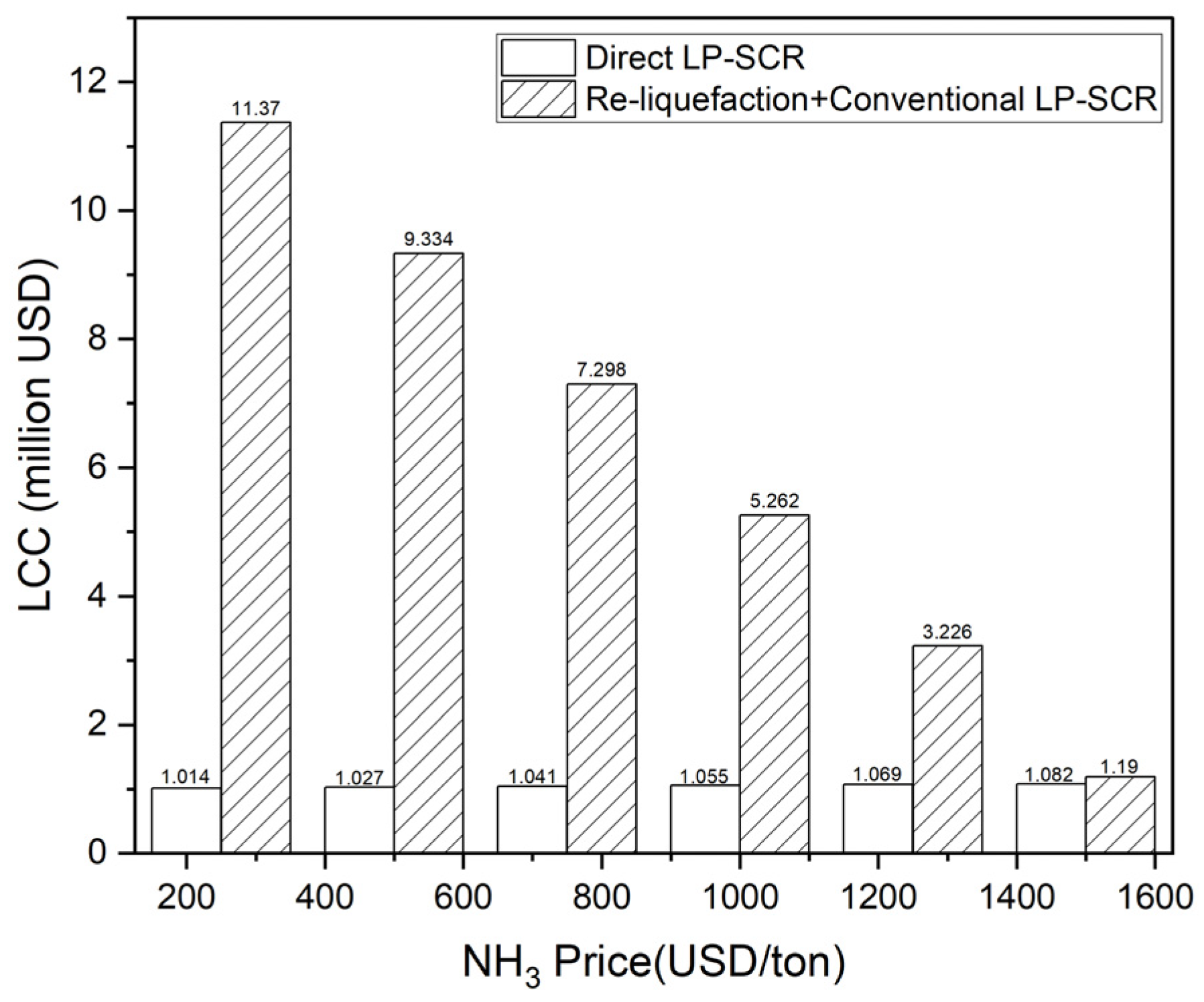
As a result, the direct LP-SCR system offers relatively stable operational costs without any significant variability due to changes in NH3 prices for ships utilizing NH3 as fuel. Three methodologies were used to determine the necessary ammonia flow rate for the LP-SCR system to ensure reliable analysis results. Furthermore, in the NH3 direct LP-SCR system, since the need for core equipment is minimal, power consumption for supplying NH3, whether as a BOG or a liquid, is comparatively low. According to the LCC analysis, the NH3 direct LP-SCR system is more cost-effective than the combination of re-liquefaction and the existing SCR system. However, the initial capital cost for the existing LP-SCR system is higher when comparing CAPEX between the re-liquefaction system, the existing LP-SCR system, and the direct LP-SCR system. If only operating costs are considered, excluding initial capital costs, the re-liquefaction system is deemed economical when the price of NH3 exceeds USD 1500 per ton.
NH3 is emerging as a major energy source due to the strengthening environmental regulations. In the previous study, the study on NH3 BOG treatment proposed a BOG re-liquefaction system integrated with the fuel supply system in an ammonia propulsion ship. According to this study, the feasible solution is proposed for solving the problems about NOX emission and BOG treatment, which are main concerns of NH3-fueled ships. The direct LP-SCR system is an attractive solution for using NH3 fuel. It is applicable to the 14,000 TEU container ships considered in this study, as well as ships using internal combustion engines with NH3 fuel. However, further research is still needed to commercialize and optimize the BOG treatment system. We hope that the results of this study will be a useful reference for supporting the research and development of ships using NH3 as fuels.

Author Contributions

Conceptualization, J.L.; Methodology, S.J.; Software, S.J.; Validation, S.J., W.J. and J.L.; Formal analysis, S.J.; Investigation, S.J.; Resources, S.J.; Data curation, W.J.; Writing—original draft, S.J.; Writing—review & editing, W.J. and J.L.; Visualization, S.J.; Supervision, J.L.; Project administration, J.L.; Funding acquisition, J.L. All authors have read and agreed to the published version of the manuscript.

Funding

This research received no external funding.

Institutional Review Board Statement

Not applicable.

Informed Consent Statement

Not applicable.

Data Availability Statement

The data are contained within this article.

Conflicts of Interest

The authors declare no conflicts of interest.

Abbreviations

The following abbreviations are used in this manuscript:
GHGGreenhouse Gas
IMOInternational Maritime Organization
MEPCMarine Environment Protection Committee
CO2Carbon Dioxide
NOxNitrogen Oxide
H2Hydrogen
NH3Ammonia
HFOHeavy Fuel Oil
LNGLiquefied Natural Gas
LPGLiquefied Petroleum Gas
LH2Liquid Hydrogen
LHVLower Heating Value
IEAInternational Energy Agency
ABSAmerican Bureau of Shipping
LRLloyd’s Register
KRKorean Register
IGCInternational Code for Construction and Equipment of Ships Carrying Liquefied Gases in Bulk
IGFInternational Code of Safety for Ships using Gases or other Low-flashpoint Fuels
PEMFCPolymer Electrolyte Membrane Fuel Cell
SOFCSolid Oxide Fuel Cell
ICInternal Combustion
NPVNet Present Value
SWIFTWhat-If Technique
HAZIDHazard Identification Study
LP-SCRDirect-low Pressure Selective Catalytic Reduction
SMCRSpecified Maximum Continuous Rating
EOSEquation of State
ppmParts Per Million
SECSpecific Energy Consumption
LCCLife Cycle Cost
CAPEXCapital Expenditure
OPEXOperational Expenditure

References

  1. IMO. Initial IMO Strategy on Reduction of GHG Emissions from Ships; IMO: London, UK, 2018. [Google Scholar]
  2. Xing, H.; Spence, S.; Chen, H. A Comprehensive Review on Countermeasures for CO2 Emissions from Ships. Renew. Sustain. Energy Rev. 2020, 134, 110222. [Google Scholar] [CrossRef]
  3. IMO. Nitrogen Oxides (NOx)—Regulation 13. Available online: https://www.imo.org/en/OurWork/Environment/Pages/Nitrogen-oxides-(NOx)-%E2%80%93-Regulation-13.aspx (accessed on 9 April 2024).
  4. Smith, T.; Shaw, A. An Overview of the Discussions from IMO MEPC 80 and Frequently Asked Questions. Read out from UMAS; UMAS: London, UK, 2023. [Google Scholar]
  5. Bilgili, L. A Systematic Review on the Acceptance of Alternative Marine Fuels. Renew. Sustain. Energy Rev. 2023, 182, 113367. [Google Scholar] [CrossRef]
  6. Lewis, J. Fuels Without Carbon: Prospects and the Pathway Forward for Zero-Carbon Hydrogen and Ammonia Fuels; Clean Air Task Force: Boston, MA, USA, 2018. [Google Scholar]
  7. Ishaq, H.; Crawford, C. Review and Evaluation of Sustainable Ammonia Production, Storage and Utilization. Energy Convers. Manag. 2024, 300, 117869. [Google Scholar] [CrossRef]
  8. Korean Register. Report on Ammonia-Fueled Ships; Korean Register: Busan, Republic of Korea, 2021. [Google Scholar]
  9. Fatih, B. Net Zero Roadmap a Global Pathway to Keep the 1.5 °C Goal in Reach; IEA: Paris, France, 2023. [Google Scholar]
  10. Zincir, B. Environmental and Economic Evaluation of Ammonia as a Fuel for Short-Sea Shipping: A Case Study. Int. J. Hydrog. Energy 2022, 47, 18148–18168. [Google Scholar] [CrossRef]
  11. Lloyd’s Register. Ships Using Gases or Other Low-Flashpoint Fuels. Available online: https://www.lr.org/en/knowledge/lloyds-register-rules/rules-and-regulations-for-ships-using-gases-or-low-flashpoint-fuels/ (accessed on 20 March 2024).
  12. Brinks, H.; Erik, W.; Hektor, A. Ammonia as a Marine Fuel; DNV Group Technology and Research: London, UK, 2020. [Google Scholar]
  13. Korean Register. Guidelines for Ships Using Ammonia as Fuels; Korean Register: Busan, Republic of Korea, 2021. [Google Scholar]
  14. Akturk, M.; Seo, J.K. The Feasibility of Ammonia as Marine Fuel and Its Application on a Medium-Size LPG/Ammonia Carrier. J. Adv. Mar. Eng. Technol. 2023, 47, 143–153. [Google Scholar] [CrossRef]
  15. Di Micco, S.; Cigolotti, V.; Mastropasqua, L.; Brouwer, J.; Minutillo, M. Ammonia-Powered Ships: Concept Design and Feasibility Assessment of Powertrain Systems for a Sustainable Approach in Maritime Industry. Energy Convers. Manag. 2024, 22, 100539. [Google Scholar] [CrossRef]
  16. American Bureau of Shipping. Setting the Course to Low Carbon Shipping; American Bureau of Shipping: Houston, TX, USA, 2019. [Google Scholar]
  17. Cames, M.; Nora, W.; Jürgen, S. Ammonia as a Marine Fuel. In Risks and Perspectives; Oko-Institut eV: Berlin, Germany, 2021. [Google Scholar]
  18. Moon, K.-T.; Davies, P.; Wright, L. Ammonia as a Marine Fuel: Likelihood of Ammonia Releases. J. Adv. Mar. Eng. Technol. 2023, 47, 447–454. [Google Scholar] [CrossRef]
  19. MAN E&S. Two-Storke Engine Operating on Ammonia; MAN E&S: Copenhagen, Denmark, 2020. [Google Scholar]
  20. Wärtsilä. World’s First Full Scale Ammonia Engine Test—An Important Step towards Carbon Free Shipping. Available online: https://www.wartsila.com/media/news/30-06-2020-world-s-first-full-scale-ammonia-engine-test---an-important-step-towards-carbon-free-shipping-2737809 (accessed on 20 March 2024).
  21. Wärtsilä. Wärtsilä Continues to Set the Pace for Marine Decarbonisation with Launch of World-First 4-Stroke Engine-Based Ammonia Solution. Available online: https://www.wartsila.com/media/news/15-11-2023-wartsila-continues-to-set-the-pace-for-marine-decarbonisation-with-launch-of-world-first-4-stroke-engine-based-ammonia-solution-3357985 (accessed on 20 March 2024).
  22. Erdemir, D.; Dincer, I. A Perspective on the Use of Ammonia as a Clean Fuel: Challenges and Solutions; John Wiley & Sons: Hoboken, NJ, USA, 2020. [Google Scholar] [CrossRef]
  23. Kim, K.; Roh, G.; Kim, W.; Chun, K. A Preliminary Study on an Alternative Ship Propulsion System Fueled by Ammonia: Environmental and Economic Assessments. J. Mar. Sci. Eng. 2020, 8, 183. [Google Scholar] [CrossRef]
  24. Lee, J.; Choi, Y.; Choi, J. Techno-Economic Analysis of NH3 Fuel Supply and Onboard Re-Liquefaction System for an NH3-Fueled Ocean-Going Large Container Ship. J. Mar. Sci. Eng. 2022, 10, 1500. [Google Scholar] [CrossRef]
  25. Seo, Y.; Han, S. Economic Evaluation of an Ammonia-Fueled Ammonia Carrier Depending on Methods of Ammonia Fuel Storage. Energies 2021, 14, 8326. [Google Scholar] [CrossRef]
  26. Lesmana, H.; Zhang, Z.; Li, X.; Zhu, M.; Xu, W.; Zhang, D. NH3 as a Transport Fuel in Internal Combustion Engines: A Technical Review. J. Energy Resour. Technol. Trans. ASME 2019, 141, 070703. [Google Scholar] [CrossRef]
  27. Jang, H.; Mujeeb-Ahmed, M.P.; Wang, H.; Park, C.; Hwang, I.; Jeong, B.; Zhou, P.; Mickeviciene, R. Regulatory Gap Analysis for Risk Assessment of Ammonia-Fuelled Ships. Ocean Eng. 2023, 287, 115751. [Google Scholar] [CrossRef]
  28. MAN E&S. Propulsion of 14000 Teu Container Vessels; MAN E&S: Copenhagen, Denmark, 2018. [Google Scholar]
  29. LNG Prime. Jiangnan Starts Work on PIL’s First LNG-Fueled Containership; LNG Prime: Sarajevo, Bosnia, 2023. [Google Scholar]
  30. John, S. World’s First LNG-Fuelled ULCS Joins CMA CGM Fleet; Riviera Maritime Media Ltd.: Enfield, UK, 2020. [Google Scholar]
  31. DNV. LNG Containment Systems: Finding the Way for Type A. Available online: https://www.dnv.com/expert-story/maritime-impact/LNG-containment-systems-finding-the-way-for-Type-A (accessed on 20 March 2024).
  32. Habibic, A. Shipbuilding Order Placed for World’s First Ammonia-Powered Containership—Offshore Energy. Available online: https://www.offshore-energy.biz/shipbuilding-order-placed-for-worlds-first-ammonia-powered-containership/ (accessed on 10 April 2024).
  33. Baboo, P. Ammonia Storage Tank Pre-Commissioning. Int. J. Eng. Res. Technol. (IJERT) 2019, 8, 612–624. [Google Scholar]
  34. Yim, S.D.; Kim, S.J.; Baik, J.H.; Nam, I.S.; Mok, Y.S.; Lee, J.H.; Cho, B.K.; Oh, S.H. Decomposition of Urea into NH3 for the SCR Process. Ind. Eng. Chem. Res. 2004, 43, 4856–4863. [Google Scholar] [CrossRef]
  35. International Maritime Organization(IMO). Amendments to the Technical Code on Control of Emission of Nitrogen Oxides from Marine Diesel EngiNES (NOx Technical Code 2008); International Maritime Organization(IMO): London, UK, 2008. [Google Scholar]
  36. MAN E&S. Emission Project Guide MAN B&W Two-Stroke Marine Engines; MAN E&S: Copenhagen, Denmark, 2024. [Google Scholar]
  37. CEAS. Engine Calculations. Available online: https://www.man-es.com/marine/products/planning-tools-and-downloads/ceas-engine-calculations (accessed on 20 March 2024).
  38. Nam, H.-S.; Hur, J.-J.; Sin, D.-U.; Rho, B.-S.; Ryu, K.-T.; Lee, Y.-H.; Kang, J.-G.; Lee, S.-W. Experimental Study on Marine SCR System. J. Korean Soc. Fish. Technol. 2020, 56, 183–192. [Google Scholar] [CrossRef]
  39. Gómez, J.R.; Gómez, M.R.; Garcia, R.F.; Catoira, A.D.M. On Board LNG Reliquefaction Technology: A Comparative Study. Pol. Marit. Res. 2013, 21, 77–88. [Google Scholar] [CrossRef]
  40. Hasan, M.H.; Mahlia, T.M.I.; Mofijur, M.; Rizwanul Fattah, I.M.; Handayani, F.; Ong, H.C.; Silitonga, A.S. A Comprehensive Review on the Recent Development of Ammonia as a Renewable Energy Carrier. Energies 2021, 14, 3732. [Google Scholar] [CrossRef]
  41. Zhu, Y.; Zhou, W.; Xia, C.; Hou, Q. Application and Development of Selective Catalytic Reduction Technology for Marine Low-Speed Diesel Engine: Trade-Off among High Sulfur Fuel, High Thermal Efficiency, and Low Pollution Emission. Atmosphere 2022, 13, 731. [Google Scholar] [CrossRef]
  42. Wang, C.; Ju, Y.; Fu, Y. Comparative Life Cycle Cost Analysis of Low Pressure Fuel Gas Supply Systems for LNG Fueled Ships. Energy 2021, 218, 119541. [Google Scholar] [CrossRef]
Figure 1. The 14,000 TEU operation profile of the target ship.
Jmse 12 00698 g001
Figure 2. Ammonia re-liquefaction system process flow diagram.
Jmse 12 00698 g002
Figure 3. Direct selective catalytic reduction system process.
Jmse 12 00698 g003
Figure 4. Urea consumption calculation results.
Jmse 12 00698 g004
Figure 5. NH3 consumption calculation results.
Jmse 12 00698 g005
Figure 6. LCC comparison of two systems.
Jmse 12 00698 g006
Table 1. NOX emission regulations (g/kWh) by year.
Engine Speed n (rpm)Tier 1Tier 2Tier 3
200020112016
<13017.014.43.4 g
130 ≤ n < 2000 45.0 × n−0.244.0 × n−0.239.0 × n−0.2
20009.8 7.7 2.0
Table 2. Comparison of characteristics of ship fuel.
PropertyUnitLNH3
LHVMJ/kg18.6
Volumetric energy densityMJ/m314,100
Densitykg/m3603
(liquid at 25 °C)
Boiling temperature
at 1 bar
°C−33.4
Condensation pressure
at 25 °C
bar9.90
Table 3. Ammonia tank sizing.
PropertyUnitValueRemark
Required energyGJ254,16012000 m3 LNG fuel tank
NH3 LHVMJ/kg18.6 Liquid saturation at 1.013 bar
NH3 densitykg/m3673.1
Required NH3 volumem320,301
NH3 fuel tank sizem320,71598% filling limit
BOR%/day0.04-
BOGkg/h232.4
Table 4. Vessel particulars of a 14,000 TEU container ship.
SpecificationUnitValue
DeadweightDwt150,000
Propeller diameterm10
Designed ship speedKnot23.5
Table 5. Specifications of the applied engine.
EngineSMCR PointNCR
12G90ME-C10.5-GI-LPSCR64,235 kW at 78 rpm54,600 kW
Table 6. Estimation of required NH3 flow rate.
MethodStrategy
Resolution MEPC.291(71)
(NOX Tech. Code)
Required NH3 flow rate based on NOX Technical Code for Control of Emission of Nitrogen Oxides from Marine Diesel Engines
MAN empirical methodMAN empirical equation:
Urea (L/h) = Engine power (kW) × 0.017
MAN CEAS engine dataUrea consumption from engine data
NH3 consumption derived from the chemical equation
Table 7. Ammonia mass flow calculations.
Load (% SMCR)Power (kW)Operation
Days
Exh. Gas Amount (kg/h)Exh. Gas Temp (°C)MAN CEAS Engine Data (kg/h)MAN Empirical Method (kg/h)NOx Tech. Code (kg/h)
UreaAmmoniaUreaAmmoniaUreaAmmonia
10064,23514132.32651187.7269.21212.1274.71145.4259.6
8554,60084116.92581209.9274.21030.3233.51012.1229.4
6541,75312690.72591132.2256.6787.9178.6785.2178.0
5032,1181472.6270987.9223.9606.1137.4628.5142.5
3522,4821452295810.3183.7424.296.2450.2102.0
2516,0592838.4287632.7143.4303.068.7332.475.4
Table 8. Design of onboard re-liquefaction system.
ItemDescription
Refrigeration cycleVapor compression
RefrigerantAmmonia
Loop pressure (bar)2 to 15.5
Mass flow (kg/h)315
BOG feed temperature (°C)−20
Suction pressure of BOG compressor (bar)1.4
BOG composition 100% ammonia
Table 9. Design of onboard direct LP-SCR system.
CompressorPump
Efficiency (%)7575
Suction temp. (°C)−20−33
Suction pressure (bar)1.41.4
Table 10. CAPEX of NH3 direct LP-SCR and re-liquefaction plus existing LP-SCR.
CaseSystemCost (Million USD)
1NH3 direct LP-SCR1
2Re-liquefaction + existing LP-SCR1.5 + 1.5
Table 11. OPEX of NH3 direct LP-SCR and re-liquefaction plus existing LP-SCR.
CaseOPEX
1Power cost for operation
2Urea consumption − (BOG recovery benefit − power cost for re-liquefaction)
Table 12. Re-liquefaction system’s power consumption.
ItemUnitValue
BOG compressorkW15.41
Re-liquefaction compressor 1kW14.42
Re-liquefaction compressor 2kW22.07
Total powerkW51.90
SECkWh/kg0.223
Table 13. Direct LP-SCR power consumption using MAN CEAS data.
Load (%)NH3 Mass Flow (kg/h)MAN CEAS
Compressor (kW)Pump (kW)SEC (kWh/kg)
1002693.890.00120.0144
852743.890.00510.0142
652573.890.00080.0151
502243.75-0.0167
351843.08-0.0167
251432.39-0.0167
Table 14. Direct LP-SCR power consumption using the MAN empirical method.
Load
(%)
NH3 Mass Flow (kg/h)MAN Empirical Method
Compressor (kW)Pump (kW)SEC (kWh/kg)
1002753.890.00140.0141
852343.89-0.0166
651793.89-0.0168
501373.75-0.0167
35963.08-0.0167
25692.39-0.0168
Table 15. Direct LP-SCR power consumption using NOx Tech. Code.
Load (%)NH3 Mass Flow (kg/h)NOx Tech. Code
Compressor (kW)Pump (kW)SEC (kWh/kg)
1002563.890.00090.0150
852263.780.00060.0165
651752.930.00030.0167
501402.34-0.0167
351011.69-0.0168
25741.24-0.0167
Table 16. Re-liquefaction system’s operating costs.
NH3 Price (USD/ton)Power Generation Cost (USD/ton)BOG Recovery Cost (USD/ton)
25033,750390,415
50067,501780,829
750101,2511,171,244
1000135,0021,561,659
1250168,7521,952,074
1500202,5022,342,488
Table 17. Conventional LP-SCR urea consumption costs.
Load (% SMCR)Urea Consumption Cost (USD/ton)
MAN CEASMAN Empirical MethodNOx Tech. Code
10099,767101,81896,212
85609,790519,272510,079
65855,943595,637593,637
5082,98450,91052,797
3568,06535,63637,816
25106,29450,91055,0851
Total1,822,8421,354,1811,346,392
Table 18. Direct LP-SCR system’s operating costs.
NH3 Price (USD/ton)Power Generation Cost (USD/ton)
MAN CEASMAN Empirical MethodNOX Tech. Code
250240019621931
500480039243863
750720058865794
1000960078487725
125012,00098109656
150014,40011,77211,588
Table 19. Direct LP-SCR system’s NH3 consumption costs.
NH3 Price (USD/ton)NH3 Consumption [USD/ton]
MAN CEASMAN Empirical MethodNOX Tech. Code
250413,178306,948305,182
500826,355613,896610,364
7501,239,533920,843915,547
10001,652,7101,227,7911,220,729
12502,065,8881,534,7391,525,911
15002,479,0651,841,6871,831,093
Disclaimer/Publisher’s Note: The statements, opinions and data contained in all publications are solely those of the individual author(s) and contributor(s) and not of MDPI and/or the editor(s). MDPI and/or the editor(s) disclaim responsibility for any injury to people or property resulting from any ideas, methods, instructions or products referred to in the content.

