Cubipod® Armor Design in Depth-Limited Regular Wave-Breaking Conditions


1
Laboratory of Ports and Coasts, Institute of Transport and Territory, Universitat Politècnica de València, 46022 Valencia, Spain
2
PROES Consultores S.A., 28020 Madrid, Spain
*
Author to whom correspondence should be addressed.
J. Mar. Sci. Eng. 2018, 6(4), 150; https://doi.org/10.3390/jmse6040150
Submission received: 17 October 2018
/
Revised: 20 November 2018
/
Accepted: 4 December 2018
/
Published: 6 December 2018
(This article belongs to the Special Issue Selected Papers from Coastlab18 Conference)
Abstract
:Armor stability formulas for mound breakwaters are commonly based on 2D small-scale physical tests conducted in non-overtopping and non-breaking conditions. However, most of the breakwaters built around the world are located in breaking or partially-breaking wave conditions, where they must withstand design storms having some percentage of large waves breaking before they reach the structure. In these cases, the design formulas for non-breaking wave conditions are not fully valid. This paper describes the specific 2D physical model tests carried out to analyze the trunk hydraulic stability of single- and double-layer Cubipod® armors in depth-limited regular wave breaking and non-overtopping conditions with horizontal foreshore (m = 0) and armor slope (α) with cotα = 1.5. An experimental methodology was established to ensure that 100 waves attacked the armor layer with the most damaging combination of wave height (H) and wave period (T) for the given water depth (hs). Finally, for a given water depth, empirical formulas were obtained to estimate the Cubipod® size which made the armor stable regardless of the deep-water wave storm.
1. Introduction
Breakwaters are usually tested using small-scale models in non-breaking wave conditions. Since the failure of large breakwaters in the late 1970s and early 1980s (e.g., Sines West Breakwater, Portugal), most physical tests have been carried out using irregular waves to better reproduce the highest waves in prototype conditions. However, most mound breakwaters are placed in depth-limited wave breaking conditions, where the highest waves break on the foreshore before reaching the structure.
Since the pioneering work of Iribarren (1938) [1], several formulas have been developed to characterize the hydraulic stability of rock armors, such as those provided by Hudson (1959) [2], Van der Meer (1988) [3], Van Gent et al. (2003) [4] and other authors. An in-depth literature review was undertaken by Herrera et al. (2017) [5]. Most of these formulas are based on 2D physical tests with models in non-breaking wave conditions. Spectral significant wave height, Hs = Hm0 = 4(m0)0.5, at the toe of the structure and wave height with a 2% exceedance probability, H2%, are usually considered to describe the incident wave characteristics in non-breaking wave conditions. H2% is strongly correlated to Hm0 in deep water when wave heights are Rayleigh-distributed, but this is not the case in depth-limited breaking wave conditions (see Battjes and Groenendijk 2000) [6].
For shallow water and horizontal foreshore, the water depth (hs) is the key variable for designing mound breakwaters because the maximum wave height (Hmax) attacking the structure mostly depends on hs. In these conditions, irregular waves may cause less armor damage than regular waves. In a given wave storm, the highest waves may break on the foreshore while smaller waves cause irrelevant armor damage; only a very low proportion of waves will have a wave height (H) close to the maximum wave height (H ≈ Hmax) to be relevant when analyzing the hydraulic stability of the armor layer. By contrast, runs of regular waves with the appropriate wave height (H) and wave period (T) can be generated in 2D physical experiments to attack the structure with many waves, say 100 waves, close to the maximum wave height, which would never be obtained with runs of a few thousand irregular waves propagating on a horizontal foreshore.
Given a water depth (hs), a test matrix of regular wave runs covering the full range of wave height (H) and wave period (T), guarantees that the structure will be attacked by many of the most damaging waves. In these conditions, armor damage under the full test matrix of regular waves is higher than damage caused by a conventional test matrix of irregular wave runs (1,000 waves). Design rules based on the results using regular waves are on the safe side because the structure in shallow water and horizontal foreshore will never be attacked by such a large number of high waves, regardless of the design storm.
This paper describes the specific 2D physical model tests carried out to analyze the hydraulic stability of single- and double-layer Cubipod® armored breakwaters on a horizontal foreshore, in depth-limited regular wave breaking and non-overtopping conditions. New empirical formulas depending on the design water depth (h) are proposed to estimate the size of Cubipod® units needed to design stable armors with cotα = 1.5 on a horizontal bottom (m = 0), for any deep-water wave climate. The paper is structured as follows: Section 2 describes the background of the research. Then, Section 3 and Section 4 describe the experimental methodology and present the experimental results, respectively. Section 5 summarizes and details the proposed design criterion.
2. Background
The armor layer of mound breakwaters is commonly designed using empirical formulas, such as those proposed by Hudson (1959) [2] or Van der Meer (1988) [3], based on 2D small-scale physical tests conducted in non-breaking and non-overtopping conditions. However, most of the breakwaters built around the world are located in breaking wave conditions, where they must withstand design storms having some percentage of large waves which break before reaching the structure. In these cases, it is not clear whether the design formulas for non-breaking wave conditions should be applied. The Hudson formula given below (Equation (1)), based on the pioneering work of Iribarren (1938) [1], was popularized by USACE (1975 and 1984) [7,8]:
where Dn is the nominal diameter of the units, Δ = (ρr − ρw)/ρw is the relative submerged mass density, ρr is the mass density of the units, ρw is the mass density of the sea water, KD is the stability coefficient, α is the armor slope, Hs is the significant wave height (Hs = H1/3 = average of one-third highest waves or Hs = Hm0 = spectral significant wave height), and Ns is the stability number.
Equation (1) was based on regular wave tests in non-breaking and non-overtopping conditions. USACE (1975 and 1984) [7,8] recommended a change in the stability coefficient (KD) to use Equation (1) in breaking wave conditions, reducing KD values for breaking waves. KD takes into account the geometry of the armor unit, number of layers, breakwater section (trunk or head), armor slope (α), and also an implicit safety factor for design (see Medina and Gómez-Martín 2012 [9]). Equation (1) does not explicitly consider the duration of the wave storm, the wave period or wave steepness, the permeability of core and filter layers, or other relevant factors affecting the hydraulic stability of the armor layer. Nevertheless, Equation (1) is still widely used by practitioners for preliminary designs and feasibility studies to compare construction costs of different breakwater designs using different armor units.
In addition, the generalized Hudson formula is extensively used in practice for single- and double-layer armors; however, this formula is not reasonable for interlocking units because interlocking increases with the armor slope. Furthermore, armor design to Initiation of Damage (IDa) popularized by USACE (1975) [7] for double-layer randomly-placed armors must be adapted to single-layer armors with brittle failure functions when IDa and Initiation of Destruction (IDe) are very close. In order to maintain a reasonable safety factor to IDe, the recommended KD for single-layer armors corresponds to an armor damage level much lower than IDa. The values of KD for single- and double-layer armors are based on small-scale physical tests and may change slightly over time, depending on experience and implicit or explicit safety factors.
For double-layer rock armors in breaking wave conditions, Van der Meer (1988) [3] proposed replacing Hs with H2%/1.4 in Equations (2) and (3), after conducting several physical tests in breaking wave conditions with an m = 1/30 bottom slope and a permeable structure. The relationship H2%/1.4 = Hs is valid if wave heights are Rayleigh distributed (non-breaking wave conditions) but it is a conservative criterion if the highest waves break before reaching the structure (breaking wave conditions).
in which Ns is the stability number, Dn50 is the equivalent cube size or nominal diameter of the units, S is the dimensionless armor damage, ξmc = 6.2P0.31(tanα)0.5)1/(P+0.5) is the critical breaker parameter, 0.1 ≤ P ≤ 0.6 is a parameter which considers the permeability of the structure, Nz is the number of waves, and ξm = tanα/(2πHs/(gTm2))0.5 is the surf similarity parameter based on the mean period, Tm.
Although several hydraulic stability formulas for rock armors are used in breaking wave conditions, considering different characteristic wave heights, most experimental validations are carried out in non-breaking wave conditions.
Melby and Kobayashi (1998) [10] and Van Gent et al. (2003) [4] also proposed hydraulic stability formulas for double-layer randomly-placed rock armors based on specific laboratory tests in breaking wave conditions (0.64 < Hs/hs < 1.11 and 0.15 < Hs/hs < 0.78, respectively) with different bottom and armor slopes. Furthermore, available formulas require knowing Hs or H2% at the toe of the structure; however, these formulas are calibrated with waves measured at a certain distance from the structure.
Van Gent (2013) [11] established that breakwaters with a berm can significantly reduce overtopping and reduce the required rock size, especially for the slope above the berm, compared to straight slopes without a berm. Van Gent (2013) [11] provided empirical relationships to quantify the required armor rock size for non-overtopped rock slopes with a horizontal berm, with a 1:2 slope above and below the berm, or a 1:4 slope above and below the berm; this formula is only valid with a horizontal foreshore on which no wave breaking occurs. Nevertheless, the experimental range investigated by Van Gent (2013) [11] is limited to rather high berms, i.e., characterized by small values of water depth over the berm compared with the water depth at the toe.
Herrera et al. (2017) [5] proposed Equation (4) for double-layer rock armors in breaking wave conditions (0.20 < Hs/hs < 0.90), considering the observed potential 6-power relationship between the equivalent dimensionless armor damage (Se) and the spectral significant wave height (Hm0) at a seaward distance of 3hs from the breakwater toe, where hs is the water depth at the toe.
Celli et al. (2018) [12] provided a design criterion for the armor layer elements of conventional breakwaters with submerged berm marked by a minimal thickness compared to water depth, extending the validity range of the method suggested by Van Gent (2013) [11].
CLI (2018) [13] specified stability coefficients for single-layer armors with AccropodeTM (KD = 15) and other interlocking armor units (KD = 16), valid for armor slopes with cotα = 1.33 to 1.5 in non-breaking conditions. CLI (2018) [13] as well as USACE (1975, 1984) [7,8] recommended using lower values of KD for wave breaking conditions. On the contrary, Xbloc® (2014) [14] recommended KD = 16 and 14.2 for armor slopes with cotα = 1.33 and 1.5, respectively, in breaking or partially breaking wave conditions (Hs/hs > 0.4), and KD = 10.7 and 8.0 for 0.29 < Hs/hs < 0.4 and Hs/hs < 0.29, respectively, when cotα = 1.33.
To rationalize the use of KD when characterizing the hydraulic stability of the armor layers, Medina and Gómez-Martín (2012) [9] proposed including explicit safety factors (SF) for IDa and IDe associated to each recommended KD. Based on the experimental results for each armor unit, the safety factors SF(IDa) and SF(IDe) are the ratio between the stability number to IDa and IDe and the design stability number (Nsd), SF(IDa) = Ns(IDa)/Nsd and SF(IDe) = Ns(IDe)/Nsd, where Nsd is given by Equation (1) when Hs = Hsd and Hsd is the design significant wave height. Medina and Gómez-Martin (2016) [15] recommended KD values for single- and double-layer Cubipod® armors in non-overtopping and non-breaking conditions, with the corresponding explicit safety factors.
3. Experimental Methodology
2D physical model tests using regular waves in breaking wave conditions were conducted in the wind and wave test facility (30 × 1.2 × 1.2 m) of the Laboratory of Ports and Coasts at the Universitat Politècnica de València (LPC-UPV). The piston-type wavemaker was equipped with an active wave absorption system (AWACS), which generates regular and irregular waves. Water surface elevation was measured using capacitance wave gauges at ten points along the wave flume. One group of four wave gauges (S1, S2, S3 and S4) was placed near the wavemaker and other group of four wave gauges (S5, S6, S7 and S8) near the model. Wave gauges of each group were distanced according to the criterion given by Mansard and Funke (1980) [16], and incident and reflected waves where separated sing the LASA-V method developed by Figueres and Medina (2004) [17]. The water depth ranged between hs(cm) = 30 and hs(cm) = 42 at the model area, and between h(cm) = 55 and h(cm) = 67 at the wave generation zone, with a 4% slope bottom transition between the two horizontal wave flume bottoms at different levels. Figure 1 shows a longitudinal cross-section of the LPC-UPV wave flume with the location of the wave gauges used in these tests.
Three models with different armoring protection (single- and double-layer Cubipod® armors with toe berm and double-layer Cubipod® armor without toe berm) were tested in breaking wave conditions, using the same core and filter layers (see Vanhoutte and De Rouck 2009) [18]. The breakwater crest elevation was high enough for non-overtopping conditions, and the armor slope was α with cotα = 1.5. The armor porosities were 39% and 40% for single-and double-layer armors. The characteristics of the core, filter and armor layer are specified in Table 1, where Dn50 is the equivalent cube size or nominal diameter of the units, D85 and D15 is the equivalent cube size corresponding to the 85% and 15% percentile, respectively, ρr is the mass density, and M is the unit mass.
The reference scale was 1/50, and the objective was to determine, for a given water depth, a unit size which made the armor safe regardless of the deep-water wave storm conditions. In wave breaking conditions, the maximum wave height attacking the breakwater depends on the water depth at the toe (hs), the wave period (T) and the bottom slope (m = 0 in this study). The worst test conditions were those generating runs of regular waves with a variety of wave periods and with series of increasing wave heights (H), for each water depth (hs). For a given water depth (hs) and a wave period (T), the energy of the wave attack on the breakwater model increased with increasing H until waves broke in the horizontal foreshore before reaching the structure.
For each water level, hs(cm) = 30, 35, 38, 40 and 42 (hs(m) = 15.0, 17.5, 19.0, etc. at prototype scale), trains of 100 regular waves with different wave periods T(s) = 0.85, 1.28, 1.70, 2.13 and 2.55 (6 < T(s) < 18 at prototype scale) were generated increasing wave height (H) from no damage up to the armor being severely damaged (IDe) or wave breaking on the foreshore. H was increased in steps of 1 cm within the range 9 ≤ H(cm) ≤ 26 (4.5 < H(m) < 13 at prototype scale). For each water depth, around 3000 waves attacked the structure, which covers the range of periods for Spanish coasts in deep water. For a given water depth (hs) and wave period (T), if H is too high, the waves break before reaching the structure and there is no damage; if H is too small, the waves will not cause the maximum damage to the structure. The methodology described above ensured that the most damaging waves attacked the structure for a given water level.
Figure 2 shows the double-layer Cubipod® armored breakwater model without toe berm, and Figure 3 shows the cross-sections of single- and double-layer Cubipod® armors with toe berm. A detail of the toe berm used in these experiments is shown in Figure 4. The toe berm was built with filter material (G1). Equivalent dimensionless armor damage (Se) was measured with the virtual net method described by Gómez-Martín and Medina (2014) [19], considering armor unit extractions, armor layer sliding as a whole, and heterogeneous packing (HeP) failure modes simultaneously. The Cubipods in the bottom armor layer were painted white to enhance color contrast, while those in the upper armor layer were painted with stripes of different colors to facilitate the visual counting. The armor was photographed before and after each run of 100 regular waves, allowing armor damage to be measured with the virtual net method. The virtual net method was applied to the photographs taken perpendicular to the armor to calculate the corresponding equivalent dimensionless damage parameter, Se. After each series of tests with constant water depth, the armor damage was obtained, considering the previous armor damage obtained for each water depth. The accumulated armor damage was measured to obtain the maximum armor damage associated to each water depth, increasing water levels from hs(cm) = 30 to 42, for each model. Different armor damage was observed for each water depth (hs); the higher the water depth, the greater armor damage.
Some long irregular wave trains were generated in this study, but they caused little damage compared to the armor damage caused by the runs of regular waves corresponding to the experimental methodology described above. Most of the higher waves of the irregular trains broke on the horizontal foreshore and only a few relevant waves attacked the structure. The methodology used in this study was defined to ensure that 100 waves attacked the armor with the most damaging combination of wave height and period for the given water depth. Therefore, the design based on the results of these experiments with regular waves in breaking conditions is on the safe side if the breakwater is placed on a horizontal sea bottom.
4. Experimental Results
According to Medina et al. (1994) [20], rough quarrystone armor damage and wave height given by USACE (1984) [8] and Van der Meer (1988) [3] follow the one-fifth power relationship, and according to Gómez-Martín and Medina (2014) [19], cube and Cubipod® armor damage observations in non-breaking conditions also follow this relationship. Therefore, the linearized equivalent dimensionless armor damage Se1/5 is used in this study to show the stability of Cubipod® armors in depth-limited wave breaking conditions.
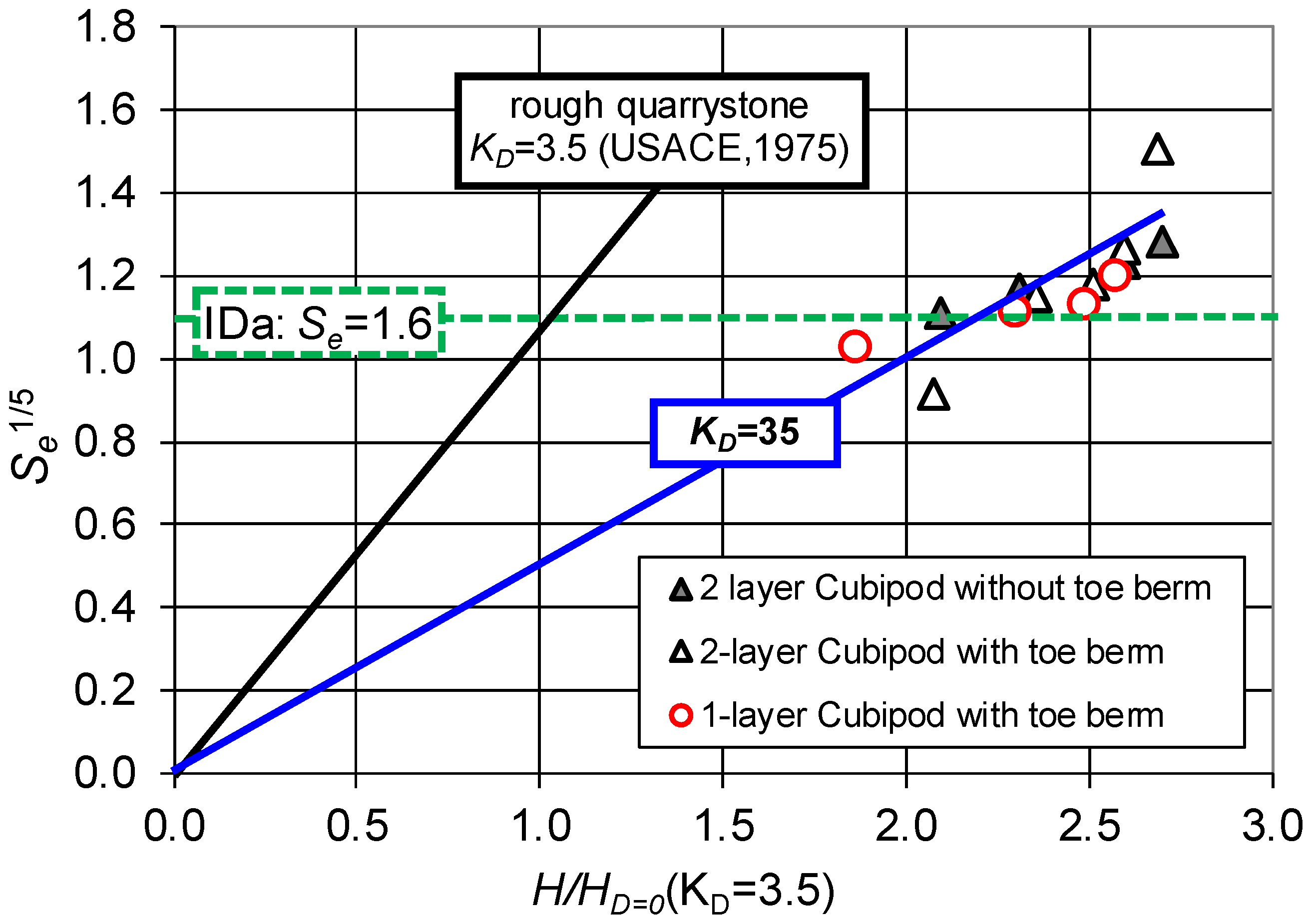
Herrera et al. (2017) [5] showed that the rough quarrystone armor damage data presented in the USACE (1975) [7] fit with the empirical Equation (5), considering KD = 3.5. Where H is the wave height corresponding to damage S, and HD=0 is the design wave height corresponding to dimensionless armor damage parameter, S = 0.7. Based on Equation (5), a general damage function (Equation (6)) for any given armor unit can be calculated taking into account the corresponding KD value.
The accumulated linearized equivalent dimensionless armor damage, Se1/5, measured in single- and double-layer Cubipod® armor experiments with and without toe berm is represented in Figure 5, as a function of the dimensionless wave height (considering the wave height, HD=0, that produces IDa in rough quarrystone (KD = 3.5) with the Hudson formula). It was observed that the KD for single- and double-layer Cubipod® armors is approximately 10 times higher than that for rough quarrystone armors in breaking-wave conditions (USACE 1975 [7]). For damage levels below IDa, the toe berm slightly increases the hydraulic stability of the double-layer Cubipod® armor; however, for armor damage above IDa, the toe berm has no significant influence on armor damage. The stability coefficient for single- and double-layer Cubipod® armors with breaking waves is KD ≈ 35 (10 times higher than KD ≈ 3.5 for rough quarrystone). The double-layer Cubipod® armors with a toe berm were tested up to hs(cm) = 42 (corresponding to 21 m at prototype scale). The other two armors were tested up to hs(cm) = 40 (20 m at prototype scale).
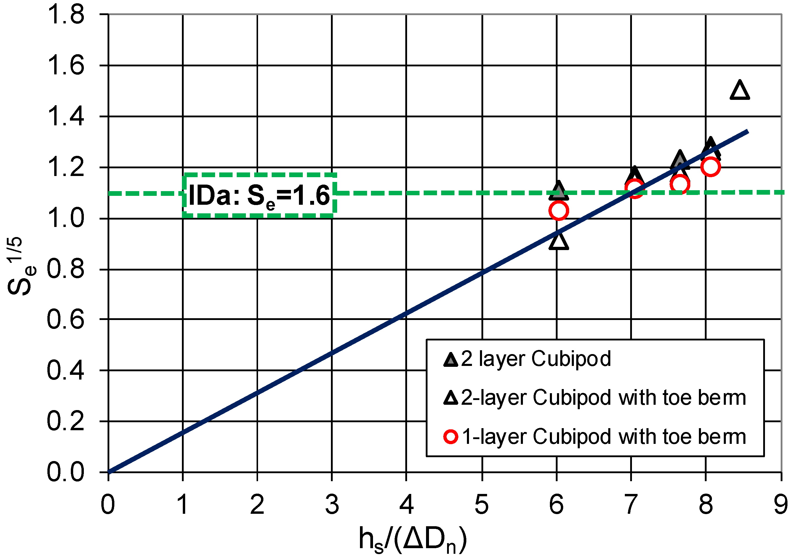
Figure 6 shows the accumulated dimensionless armor damage as a function of the measured water depths at the toe of the structure. Given the observed relationship (Figure 6) between the dimensionless water depth (hs/ΔDn) and the linearized equivalent dimensionless armor damage (Se1/5), Equation (7) is proposed as the dimensionless failure function to describe the hydraulic stability of Cubipod® armored breakwaters on horizontal bottoms in depth-limited wave breaking conditions.
where Se is the equivalent dimensionless armor damage, hs is the water depth at the toe of the structure, Δ is the relative submerged mass density, and Dn is the nominal diameter or equivalent cube side length.
Considering that IDa corresponds to an equivalent dimensionless damage 1.0 < Se < 2.0, say Se = 1.6, then hs < 7.0(ΔDn) is the water depth which guarantees that both single- and double-layer armors will not exceed IDa under any deep water wave climate conditions. Furthermore, the tests carried out indicate a relevant safety margin to IDe. Taking a safety factor SF(IDe) = 1.15 for double–layer Cubipod® armors and SF(IDe) = 1.30 for single–layer Cubipod® armors, the following design values (Equations (8) and (9)) are obtained for safe Cubipod® armored breakwaters placed on horizontal seafloors (m = 0):
hs < 7.0(ΔDn) for double-layer Cubipod® armors
hs < 6.2(ΔDn) for single-layer Cubipod® armors
Figure 7 shows an example of the incident wave height (H) measured at the model area as a function of the incident wave height measured at the wave generation zone, corresponding to a water depth hs(cm) = 30 and double-layer Cubipod® armored model without toe berm.
The highest wave heights measured in the model area were approximately 60% of the water depth, Hmax/hs≈0.60 with a horizontal seafloor (m = 0). For gentle bottom slopes (m > 0), a criterion similar to that proposed by Goda (2010) [21] and Herrera et al. (2017) [5] is reasonable. The design water depth (h) is calculated at a distance three times the water depth at the toe of the structure (hs), h = hs(1 + 3m). This approximation is reasonable for gentle bottom slopes (m ≤ 0.02); for steep bottom slopes (e.g., m = 0.10), the toe berm design is critical, and armor layer and toe berm must be studied simultaneously (see Herrera and Medina 2015 [22] or Herrera et al. 2016 [23]). Small-scale models are highly recommended when breakwaters are placed on steep sea bottoms in depth-limited breaking wave conditions.
Once the design water depth is calculated, h = hs(1 + 3m), the size of Cubipod® units can be estimated to design safe Cubipod® armored breakwaters (cotα = 1.5 and perpendicular wave attack) for any deep water wave climate, regardless of the wave height at the toe of the structure, considering the following equations:
Dn > h/7.0Δ = hs(1 + 3m)/(7.0Δ) for double-layer Cubipod® armors
Dn > h/6.2Δ = hs(1 + 3m)/(6.2Δ) for single-layer Cubipod® armors
5. Summary and Conclusions
The armors of conventional mound breakwaters are usually pre-designed using simple empirical equations such as the Hudson formula, based on results from small-scale physical tests with Froude similarity. Most of the tests used to characterize the hydraulic stability of different armor units are conducted in non-overtopping and non-breaking conditions. However, most of the world’s breakwaters are built to withstand design storms having some percentage of large waves breaking before reaching the structure and in depth-limited breaking wave conditions. Nevertheless, there are few studies in the literature, and often with contradictory recommendations, to design breakwaters in breaking wave conditions based on formulas validated with experiments in non-breaking wave conditions.
A specific experimental methodology is described to analyze the hydraulic stability of Cubipod® armored breakwaters on horizontal seafloors in depth-limited breaking wave and non-overtopping conditions. This methodology ensures that the main armor is attacked by runs of 100 regular waves with the most damaging combination of wave height (H) and period (T) for the given water depth (hs). In wave breaking conditions, the maximum wave height attacking the breakwater (Hmax) depends on the water depth at the toe (hs), the wave period (T) and the bottom slope (m = 0 in this study). This research verifies that, for a given water depth, any irregular wave train caused less armor damage compared to that caused by the series of regular waves corresponding to the experimental methodology used in this study. The worst test conditions were obtained generating regular waves for a range of wave height and periods, which can be observed in nature; for each water depth (hs) and wave period (T), a series of runs of 100 waves with increasing wave heights (H) was generated until waves broke on the foreshore before reaching the structure. The accumulated equivalent dimensionless armor damage (Se) was measured to obtain the maximum armor damage associated with each water depth (hs) and multiple combinations of wave height (H) and wave period (T).
Considering that IDa corresponds to an equivalent dimensionless damage Se = 1.6 and a safety factor SF(IDe) = 1.15 and 1.30 for double- and single-layer Cubipod® armors, respectively, the water depths at the toe of the structure which guarantee that both double- and single-layer armors will not exceed IDa are hs < 7.0(ΔDn) and hs < 6.2(ΔDn), respectively. Armor unit size can be estimated with Equations (10) and (11) to design safe Cubipod® armored breakwaters on horizontal seafloors with cotα = 1.5 for any deep-water wave climate. Taking a design water depth (h) at a distance three times the water depth at the toe of the structure, h = hs(1 + 3m), Equations (10) and (11) can be safely be used to design Cubipod® armored breakwaters on gentle bottom slopes (0 ≤ m ≤ 0.02) regardless of the wave height at the toe of the structure and deep-water wave climate.
Author Contributions
M.E.G.-M. wrote the original draft and was responsible for the conceptualization, experimental methodology, and analysis. M.P.H., J.A.G.-E. and J.R.M. supervise the investigation, review and approved the manuscript.
Funding
This research was funded by Conselleria d’Educació, Investigació, Cultura i Esport (Generalitat Valenciana) under grant GV/2017/031.
Acknowledgments
The authors thank data provided by SATO-OHL Group (Cubipod Project 2007–2009). The authors thank Debra Westall for revising the manuscript.
Conflicts of Interest
The authors declare no conflict of interest.
References
- Iribarren, R. Una Fórmula Para el Cálculo de los Diques de Escollera; M. Bermejillo-Pasajes: Madrid, Spain, 1938. [Google Scholar]
- Hudson, R.Y. Laboratory investigation of rubble-mound breakwaters. J. Waterw. Harbors Div. 1959, 85, 93–121. [Google Scholar]
- Van der Meer, J.W. Rock Slopes and Gravel Beaches under Wave Attack. Ph.D. Thesis, Technical University of Delft, Delft, The Netherlands, 1988. [Google Scholar]
- Van Gent, M.R.A.; Smale, A.J.; Kuiper, C. Stability of rock slopes with shallow foreshores. In Proceedings of the Coastal Structures 2003, Portland, OR, USA, 26–30 August 2003; pp. 100–112. [Google Scholar]
- Herrera, M.P.; Gómez-Martín, M.E.; Medina, J.R. Hydraulic stability of rock armors in breaking wave conditions. Coast. Eng. 2017, 127, 55–67. [Google Scholar] [CrossRef]
- Battjes, J.A.; Groenendijk, H.W. Wave height distributions on shallow foreshores. Coast. Eng. 2000, 40, 161–182. [Google Scholar] [CrossRef]
- United States Army Corps of Engineers (USACE). Shore Protection Manual; U.S. Army Coastal Engineering Research Center, U.S. Army Engineer Waterways Experiment Station: Vicksburg, MI, USA, 1975. [Google Scholar]
- United States Army Corps of Engineers (USACE). Shore Protection Manual; U.S. Army Coastal Engineering Research Center, U.S. Army Engineer Waterways Experiment Station: Vicksburg, MI, USA, 1984. [Google Scholar]
- Medina, J.R.; Gómez-Martín, M.E. KD and safety factors of concrete armor units. Coast. Eng. Proc. 2012, 1, 29. [Google Scholar] [CrossRef]
- Melby, J.A.; Kobayashi, N. Progression and variability of damage on rubble mound breakwaters. J. Waterw. Port Coast. Ocean Eng. 1998, 124, 286–294. [Google Scholar] [CrossRef]
- Van Gent, M.R. Rock stability of rubble mound breakwaters with a berm. Coast. Eng. 2013, 78, 35–45. [Google Scholar] [CrossRef]
- Celli, D.; Pasquali, D.; De Girolamo, P.; Di Risio, M. Effects of submerged berms on the stability of conventional rubble mound breakwaters. Coast. Eng. 2018, 136, 16–25. [Google Scholar] [CrossRef]
- Concrete Layer Innovation (CLI). 2018. Available online: http://www.concretelayer.com/documentation (accessed on 8 Febrary 2018).
- Xbloc. Guidelines for Xbloc Concept Designs. 2014. Available online: https://www.xbloc.com/sites/default/files/domain-671/documents/xbloc-design-guidelines-2014-671-15039173271578936988.pdf (accessed on 8 February 2018).
- Medina, J.R.; Gómez-Martín, M.E. Cubipod® Manual 2016; Editorial Universitat Politècnica de València: Valencia, Spain, 2016; Available online: http://hdl.handle.net/10251/72310 (accessed on 8 February 2018).
- Mansard, E.P.D.; Funke, E.R. The measurement of incident and reflected spectra using a least squares method. In Proceedings of the 17th International Conference on Coastal Engineering, Sydney, Australia, 23–28 March 1980; pp. 154–172. [Google Scholar]
- Figueres, M.; Medina, J.R. Estimation of incident and reflected waves using a fully non-linear wave model. In Proceedings of the 29th International Conference on Coastal Engineering; ASCE: Reston, VA, USA, 2004; Volume 1, pp. 594–603. [Google Scholar]
- Vanhoutte, L.; De Rouck, J. Hydraulic Stability of Cubipod Armour Units in Breaking Conditions. Master’s Thesis, Ghent University, Ghent, Belgium, June 2009. Available online: https://lib.ugent.be/catalog/rug01:001418208 (accessed on 19 February 2018).
- Gómez-Martín, M.E.; Medina, J.R. Heterogeneous packing and hydraulic stability of cube and Cubipod armor units. J. Waterw. Port Coast. Ocean Eng. 2014, 140, 100–108. [Google Scholar] [CrossRef]
- Medina, J.R.; Hudspeth, R.T.; Fassardi, C. Breakwater armor damage due to wave groups. J. Waterw. Port Coast. Ocean Eng. 1994, 120, 179–198. [Google Scholar] [CrossRef]
- Goda, Y. Random Seas and Design of Maritime Structures, 3rd ed.; World Scientific: Singapore, 2010; p. 708. [Google Scholar]
- Herrera, M.P.; Medina, J.R. Toe berm design for very shallow waters on steep sea bottoms. Coast. Eng. 2015, 103, 67–77. [Google Scholar] [CrossRef] [Green Version]
- Herrera, M.P.; Molines, J.; Medina, J.R. Hydraulic stability of nominal and sacrificial toe berms for mound breakwaters on steep sea bottoms. Coast. Eng. 2016, 114, 361–368. [Google Scholar] [CrossRef]
Figure 1.
Longitudinal cross-section of the Laboratory of Ports and Coasts at the Universitat Politècnica de València (LPC-UPV) wave flume (dimensions in meters).
Figure 1.
Longitudinal cross-section of the Laboratory of Ports and Coasts at the Universitat Politècnica de València (LPC-UPV) wave flume (dimensions in meters).

Figure 2.
View of a double-layer Cubipod® armored breakwater model without toe berm tested at the LPC-UPV.
Figure 2.
View of a double-layer Cubipod® armored breakwater model without toe berm tested at the LPC-UPV.

Figure 3.
Cross-sections of (a) single- and (b) double-layer Cubipod® models with the toe berm.

Figure 4.
Toe berm used in the experiments: (a) Cross-section and (b) zenithal view.

Figure 5.
Accumulated linearized equivalent dimensionless armor damage (Se1/5) as a function of dimensionless wave height in wave breaking conditions for single- and double-layer Cubipod® armors with and without toe berm.
Figure 5.
Accumulated linearized equivalent dimensionless armor damage (Se1/5) as a function of dimensionless wave height in wave breaking conditions for single- and double-layer Cubipod® armors with and without toe berm.

Figure 6.
Linearized equivalent dimensionless armor damage Se1/5 as a function of the dimensionless water depth.
Figure 6.
Linearized equivalent dimensionless armor damage Se1/5 as a function of the dimensionless water depth.

Figure 7.
H measured at the model area as a function of H measured at the wave generation zone (m = 0).
Figure 7.
H measured at the model area as a function of H measured at the wave generation zone (m = 0).


Table 1.
Characteristics of the tested models.
| Materials | Dn50 (cm) | D85/D15 | ρr (g/cm3) | M (g) |
|---|---|---|---|---|
| Core (G2) | 0.70 | 2.0 | 2.70 | 0.9 |
| Toe berm and filter (G1) | 1.80 | 1.5 | 2.70 | 16 |
| Cubipod® | 3.82 | - | 2.30 | 128 |
© 2018 by the authors. Licensee MDPI, Basel, Switzerland. This article is an open access article distributed under the terms and conditions of the Creative Commons Attribution (CC BY) license (http://creativecommons.org/licenses/by/4.0/).
Share and Cite
MDPI and ACS Style
Gómez-Martín, M.E.; Herrera, M.P.; Gonzalez-Escriva, J.A.; Medina, J.R. Cubipod® Armor Design in Depth-Limited Regular Wave-Breaking Conditions. J. Mar. Sci. Eng. 2018, 6, 150. https://doi.org/10.3390/jmse6040150
AMA Style
Gómez-Martín ME, Herrera MP, Gonzalez-Escriva JA, Medina JR. Cubipod® Armor Design in Depth-Limited Regular Wave-Breaking Conditions. Journal of Marine Science and Engineering. 2018; 6(4):150. https://doi.org/10.3390/jmse6040150
Chicago/Turabian StyleGómez-Martín, M. Esther, María P. Herrera, Jose A. Gonzalez-Escriva, and Josep R. Medina. 2018. "Cubipod® Armor Design in Depth-Limited Regular Wave-Breaking Conditions" Journal of Marine Science and Engineering 6, no. 4: 150. https://doi.org/10.3390/jmse6040150
Note that from the first issue of 2016, this journal uses article numbers instead of page numbers. See further details here.