Survey on Experimental and Numerical Approaches to Model Underwater Explosions


University of Bologna, Interdepartmental Center for Industrial Research on Advanced Mechanics and Materials, Viale del Risorgimento 2, 40136 Bologna, Italy
J. Mar. Sci. Eng. 2019, 7(1), 15; https://doi.org/10.3390/jmse7010015
Submission received: 29 October 2018
/
Revised: 10 December 2018
/
Accepted: 8 January 2019
/
Published: 15 January 2019
(This article belongs to the Special Issue Engineering Mathematics in Ship Design)
Abstract
:The ability of predicting material failure is essential for adequate structural dimensioning in every mechanical design. For ships, and particularly for military vessels, the challenge of optimizing the toughness-to-weight ratio at the highest possible value is essential to provide agile structures that can safely withstand external forces. Exploring the case of underwater explosions, the present paper summarizes some of the fundamental mathematical relations for foreseeing the behavior of naval panels to such solicitation. A broad state-of-the-art survey links the mechanical stress-strain response of materials and the influence of local reinforcements in flexural and lateral-torsional buckling to the hydrodynamic relations that govern the propagation of pressure waves prevenient from blasts. Numerical simulation approaches used in computational modeling of underwater explosions are reviewed, focusing on Eulerian and Lagrangian fluid descriptions, Johnson-Cook and Gurson constitutive materials for naval panels, and the solving methods FEM (Finite Element Method), FVM (Finite Volume Method), BEM (Boundary Element Method), and SPH (Smooth Particle Hydrodynamics). The confrontation of experimental tests for evaluating different hull materials and constructions with formulae and virtual reproduction practices allow a wide perception of the subject from different yet interrelated points of view.
1. Introduction
Acknowledging how to properly soften the effects of impact-related damage is an imperative design guideline in shipbuilding. Specially for military applications, underwater explosions (UNDEX) prevenient from subsea blast loads can infer irreparable structural impairment to vessels, where the dynamic response of ships depends on the influence of several parameters, such explosive power, blast distance, hull panel composition, and reinforcements. The mechanics involved in ship collisions and impact can thus be looked at from two inter-dependent perspectives [1], where the external mechanics describe the hydrodynamics surrounding the vessel and the magnitude with which they affect it, and the internal mechanics that regard how the materials respond to these forces and dissipate energy through strain.
The necessary comprehension of the materials behavior goes beyond traditional steels, whereas modern designs utilize advanced metallic alloys [2], composite structures (either purely polymeric, as in the case of small and medium sized boats [3], or in a sandwich layout composed by metal sheets and foam cores [4]) and wood [5]. Also, the usage of innovative materials, such as polymers reinforced by natural fibers, have been addressed in the literature, on one hand presenting inferior mechanical properties to carbon or glass fiber, and on the other having enhanced sustainability [6]. In addition, the diverse existent hull architecture requires the designer not only to master different materials, but also to understand the response of the vessel itself as a composition of the several interlinked structural elements built with those materials, such as panels, stiffeners, and girders. The way in which these structures are realized and arranged ultimately determines the resistance of the ship and define if reinforcements like stiffeners and girders apply, and what is the optimal geometry for plate cutouts (e.g., for hatches) to avoid undesired elastoplastic deformations to buckling [7,8,9].
External mechanics, in turn, involves a series of differential hydrodynamic relations that describe the propagation of intermittent pressure waves caused by explosions defining the velocity, temperature, period, and force with which hulls are hit. The consequent fluid-structure interactions with relevant severity do not only involve liquid matter; gas bubbles generated by the blasts can also cause noticeable damage given the high pressure and temperature they may present [10,11].
The relevance of UNDEX for military purposes is clear, as highlighted in studies dated from 1990 [12], which explicitly express the cold war as the impetus for such research initiative, stating as border condition for the case study a soviet missile impacting a double-hulled structure. The aforementioned work defined through a series of experiments the strongest parameters that influence UNDEX effects as being: enthalpy of detonation, number of moles of gas, molecular weight of gas, and solid phase density.
The strategic usage of the arctic ocean as an operational area for submarines has also had its importance reflected by studies such as Barash’s [13], which analyze the effect of UNDEX beneath artic ice, not only to improve the safety of those vessels to enemy blasts, but also to allow them to have quick access to the surface by breaking ice packs using explosives. Potentially harmful debris originated from the blasts were addressed by Bryant [14], concluding that little or no metallic debris are deposited in the medium during early bubble oscillations, whereas they are actually transported by the bubbles and released in a certain area as the oscillations terminate.
Early analyses on the physics of the pressure waves were also performed. Snay [15] confirmed that the pulse shape of waves varies during their propagation in the water, where the steepness of the pressure at the head of the wave rises until the formation of an impact front. However, the author states the validity of approximating UNDEX to acoustic waves (which do not change their shape) for the solution of interaction problems, modelling them as small-amplitude constant-sound-velocity waves.
The scientific way of approaching UNDEX problems itself is an issue with distinct propositions in precursor military-grade reports. O’Daniel et al. [16] evaluated the mechanics of bubble jets, suggesting that such analysis could be conducted by performing three experiments of bubble jet strike on vertical targets in different scales: a small-scale one to study the phenomenology of the bubble jet; a mid-scale one to measure the loads applied by these jets on targets; and a large-scale one for the structural response of targets. Miller [17] categorized three fundamental steps: comparison of structural response to conventional and nuclear pressure profiles, followed by finite element analysis, and then by writing an appropriate computational numerical code to describe the experiments. Naturally, since then, computer-aided simulations have been immensely improved, as shown hereby.
Built upon classic mathematical models, numerical simulation software is a well-established time-saving tool for yielding precise UNDEX results, leaving aside the need for resource costly experimental tests. In marine engineering, accurate virtual reproductions can be done for UNDEX provoked pressure waves [18] and bubbles [19] over vessels, as well as water blast on sandwich panels [4] and cavitation in propellers [20]. For that, a variety of constitutive material models and numerical solving techniques may be used. Given the importance of understanding how external and internal mechanics work and relate, the present work briefly summarizes the fundamental numerical expressions of each one, giving also a glance in how they are usually represented in numerical simulations.
Portraying the three independent but correlated parts of UNDEX described by the navy as shown in Brenner et al. [21], i.e., the responses of water, of the vessel structure, and of the materials to the shock waves, Figure 1 depicts through a flow chart scheme the aspects approached in this work in an orderly manner. In other words, the current state-of-the-art explains how the pressure impulse propagates through water and with which magnitude it hits the ship (taking into account pressure waves and bubbles), how the ship structure responds to this impulse, and in which way the material components of the hull absorb this energy, deform, and eventually fail.
The characterization of such phenomena is hence made through analytical models, and directions on how to reproduce all the three steps by numerical simulation are also given. Some fundamental notions are provided on Eulerian, Lagrangian, and Aleatory Lagrangian-Eulerian (ALE) fluid descriptions on Finite Element and Volume Methods (FEM and FVM, respectively), Boundary Element Method (BEM), and Smoothed Particle Hydrodynamics (SPH) numerical modelling techniques, and on Johnson-Cook’s and Gurson’s constitutive materials.
Acknowledging that the study of UNDEX phenomena is an intricate and wide field of study with deeper aspects to be considered, some of its basic yet most important parameters are hereby summarized and briefly explained, intending to allow the comprehension of fundamental notions of the subject based on a thorough literature survey.
2. Analytical Models
2.1. Hydrodynamics and Fluid-Structure Impact
Amongst the challenges in ship design, there are several forces to be taken into account that may act either separately or combined over the structure originated from gravity, wind pressure, friction, freight, and hydrostatic lifting force, which can infer massive shear and torsional efforts given the large size of a ship and due to its weight distribution. Moreover, fluid-structure interactions (FSI), such as pressure waves, gas bubbles, cavitation, and underwater explosions also have the potential to cause significant damage, given that water transmits explosive energy much more efficiently than air [16].
Differently from solid-particle impacts, where a specific damage is locally caused by a particularly shaped projectile [22], in UNDEX, all the extension of the hull reachable by the same pressure wave is approximately equally impaired. These spherical waves originate a mass flow behind them (i.e., the afterflow), which leads to the formation of bubbles that can be regular UNDEX bubbles, steam bubbles in the case of nuclear explosions, or cavitation bubbles in the case of explosions that do not provoke gases [15].
Bubbles generated by UNDEX, for instance, which constitute hot air masses that can hit a vessel in more than 10 consecutive waves [23], can reach impact pressures of up to 15% of the wave pressure [11], causing significant damage and even a potential and dangerous match in resonance frequencies with the ship. Furthermore, Cui et al. [24] experimentally analyzed the mechanics of these bubbles, finding out that the pressure peaks they induce on the impacted body is highly dependent on their shape before collapse, given that the less spherical and more asymmetrical it is, the smaller is the pressure due to the influence of splashing jet water. The shape of bubbles, as shown by Gong et al. [19], is directly related to the position of the explosive charge in relation to the hull.
The response to underwater explosions is a topic of interest for military purposes, given that even if the hull is not directly hit by a torpedo or collided to other structures, the sole propagation of energy from a far blast center through water is capable of causing significant damage to the ship. This energy release can include gas bubbles at nearly 3000 °C and pressures up to 5 GPa, besides solid particles made from lead or alumina, for instance, which altogether may impact the hull’s surface at nearly the velocity of sound [10].
It is possible to quantify the pressure in the proximity of the wave front P(t) if the charge is detonated at less than 100 m in depth [25] by the expression of Equation (1) [10]:
where the time constant can be defined by Equation (2) [10]:
where is the ratio between the distance of the explosion center and the quotient of the measured location R by the initial radius of the spherical explosive R0. The peak pressure Pm (MPa) and the time decay constant (ms) can also be defined as a function of the charge load W and the standoff distance S (Equations (3) and (4), respectively) [26]:
where and are constants, which highlights that it is important to notice the discrepancies found in the literature for them. While [26,27] adopt as 1.13, [18] considers 1.81. By its turn, is adopted as 148.93 in [26], 52.16 in [27], and 29.9 in [18]. In addition, [26] considers Equation 3 valid when the measuring point is located until 10 times the explosion radius, while [18] states that the adequate tolerance distance is up to 6 times the charge radius.
When the underwater wave passes through a certain point in space, it is then submitted to a transient pressure P(t) and displaced in a velocity v(t) in the direction of the flow. Considering a spherical flow, it is possible to estimate and correlate both into the same time-dependent Equation (5) [26], where the first term stands for the velocity of a plane wave, and the second, called “after flow” term, is important for large time intervals and for when the measuring point is close to the explosions, i.e., the standoff is low.
Although the strongest shock wave comes along with the first UNDEX impact, it is important to acknowledge that the explosion damage is characterized by repetitive impacts originated in the explosion center, which intensity decays exponentially when hitting a marine structure [28], and the second impact can even be the most damaging one due to the bubble pulse, especially to air-backed hull panels [29]. This concept is illustrated in Figure 2.
2.2. Structural Response
Structural elements are meant to be strategically assembled in the construction of ships in places where they can aggregate normal, shear, or torsional resistance to the vessel, preferably in profiles and shapes that favor their mechanical properties and account for the lowest weight attainable. The main structures are longitudinal and transversal girders and stiffeners, providing enhanced resistance to underwater or contact explosions compared to unstiffened vessels [30]. These can grant noticeable economy without compromising strength and durability if stiffeners are adequately positioned at regular gaps, while dividing the hull shell into lattices in which the intersection point between transversal and longitudinal girders are the most resistant zones [31].
Hung et al. [30] have demonstrated experimentally the importance of stiffeners by performing underwater explosion tests on 3 cylindrical specimens, one being unstiffened, one externally, and one internally stiffened with welded rings. The latter showed much smaller strain, pressure, and fluid acceleration inside the coupon. Ming et al. [18] have complemented this approach by numerically and experimentally studying the reaction of plates reinforced with “T” profile stiffeners placed in the opposite side of an underwater explosion, demonstrating the damage steps of the reinforced plate. The study states that after both the plate and the stiffeners are initially damaged due to pressure waves, the panel in the lattice is torn, leading to the collapse of the longitudinal and transversal stiffeners joints, weakening the whole structure significantly.
Gordo et al. [32] have developed a numerical method to estimate the ultimate longitudinal strength of the hull girder, yielding accurate confrontations against similar approaches and the real ship failure. The compression strength of stiffened plate columns at a determined strain is defined by two independent expressions that describe flexural buckling () and lateral-torsional buckling (or tripping) (). The first is described by Equation (6):
where is based on the Johnson-Ostenfeld formulation that considers inelastic effects during buckling [33], and the second term of the equation stands for the actual degradation of the plate due to compression loading. is the sectional area, b is the breadth of plating between longitudinal stiffeners, l is the length of the stiffeners, and is the effective width of the plate given by Equation (7):
where is the slenderness of the plate equal to , in which the second term represents the instantaneous strain. In turn, the tripping strength can be calculated by Equation (8):
The first term stands for the maximum elastic tripping stress, and the second to the strain of maximum load. It is important to highlight that the resistance of the girder can be affected by residual stress and external agents such as corrosion [32], and that although both influence the behavior of the material, they should not be taken into account simultaneously, given that while residual stress acts mainly in the beginning of the operational life of the ship, corrosion is negligible in the beginning and increases with time. To avoid lateral-torsional bending in ships, the influence of the residual stress over the ultimate bending moment is quantified in Equation (9):
where is the residual stress of the panels in compression and and are, respectively, the ultimate bending moment with and without residual stress.
Innovative mechanical reinforcement techniques that go beyond classic metallic structures have also been studied, such as rubber coated ships [34], which show the ability of damping the high-frequency response from pressure waves, helping to keep the integrity of the vessel to crashes and close-range underwater explosions that may cause elastic and even plastic deformations to the side structures. However, this coating is not so effective regarding low-frequency whipping motions caused by gas bubbles.
2.3. Material Response
The first important material feature that comes to mind when one needs a vessel design to withstand impact and wear solicitations is high mechanical resistance thresholds [35,36]. However, in addition to being tough, building materials must also be as lightweight as possible to consume less fuel, leave room for more load bearing capacity and to provide the ability to quickly overcome inertia when maneuvering, especially in the case of military vessels, to make them difficult targets.
The study of metallic phases and alloys figure as an important resource to understand and improve the resistance of military naval structures to underwater explosions [37], especially in terms of the high inherent density attributed to metals. Latourte et al. [2] compared experimentally and numerically high-strength martensitic and austenitic alloys, investigating their deformation and fracture characteristics, where the first was designed to present higher fracture toughness and maximum strength, while the latter has a better uniform ductility, avoiding premature necking and consequent localized failure. The interesting outcome is that the martensitic steel was found out to sustain underwater fluid-structure impacts better, where the force magnitude needed to infer failure is 25% higher than for austenitic steel (although the austenitic performance can be improved by tempering) [2].
Besides traditional monolithic metals, the coupling of different materials in sandwich layouts have presented interesting features relevant for ship design, like the flexibility in the core constitution, which can lead to a stiffer overall material in the through-the-thickness direction, or can soften and dampen impact and decrease the force transmission to the supporting structure [4]. Furthermore, sandwich panels present an enhanced performance against underwater fluid shocks when compared to single-constituent elements of equal weight [38,39].
Fan et al. [40] investigated the response of sandwich panels with aluminum sheet skin and a honeycomb core to underwater blasts, comparing the results with monolithic plates of equivalent mass, proving a better performance of the sandwich both in terms of deformation resistance and secondary pressure wave intensity. The first advantage can be furthermore improved by increasing the equivalent thickness of the composite. As for composites with polymeric matrix, Gong et al. [19] studied the transient behavior of glass-epoxy composites to UNDEX, showing that although a composite hull might amortize the effects of bubble impacts better than steel, it becomes more susceptible to global mechanical effects, not only local ones as would be the case for metals.
In an experimental underwater explosion test, it is also possible to identify the energy absorption capacity of a certain material by analyzing its deflection, once it has been proved that during plastic regime deformation, the ability of the material to absorb energy is proportional to the square of its deflection [23]. Another important aspect is the specimen geometry to be adopted in a bulge test, given that parabolic and spherical shapes absorb practically the same energy, while conical and hyperbolic absorb only half of that considering the same bulge depth [27]. Regarding experimental tests, it is possible to predict the maximum von Mises stress for both thin circular () [41] and rectangular plates () [42], as shown respectively in Equations (10) and (11), considering that it is an explosion with low intensity (for specimens farther from the charge more than 10 times its explosion radius) and that the deformation is realized within the elastic regime.
where E is the elastic modulus and is the density of the plate material, is the density of water, c is the velocity of sound in the water medium, Pm is the peak pressure, is the angle of incidence to the plate, and is the Poisson’s ratio. In order to indicate the level of damage caused by a shock, the shock factor index (SF) is used as displayed in Equation (12) [42]. To verify whether the shock energy can cause yielding to a thin air backed plate, the yield shock factor (SFy) would have to reach the limiting value expressed by Equation (13) [42].
where W is the TNT equivalent of charge quantity (kg), S is the standoff from the explosion center, t is the thickness of the plate, is the yield stress of the plate material, Y is the yield factor equivalent to 2.212 × 10⁻⁹ for circular plates (Yc), and 1.997 × 10⁻⁹ for rectangular ones (Yr), and stands for the coupling factor, which is a function of the incidence angle as shown in Equation (14).
It is also possible to determine the yielding shock factor (SFy) as a function of the necessary charge quantity W (Equation (15)) or the standoff S (Equation (16)) and a time constant (ms).
As for the outcome material damage, it mainly depends on the material, boundary conditions, and loading rate considered. Ming et al. [18] have shown through experiments the particular case of clamped flat metal plates, in which damage can be visually categorized in three subsequent steps. The formation of a localized protuberance in the point of maximum stress immediately before the material fracture takes place (“bulging”), leads to detachment of a small metal fragment giving place to a hole (“discing”), whose size is determined by the plate thickness, charge weight, and yield stress [26,43] that continues to grow until the material dissipates this energy through the propagation of radial and equally spaced cracks, deforming the metal in petals (“petaling”), as detailed in Figure 3. A particular aspect noticed by this study is that while the hole size is sensitive to the peak pressure, the deflection near the whole is strongly affected by the impulse of the explosion.
The hole radius R found in the discing step was calculated by Rajendran et al. [43], as described in Equation (17):
where is the ratio of effective work, Ei is the inner energy per unit mass of the explosive, and is the fracture strain. Before that, while the material is in the bulging stage, its round-shaped deformation can be calculated by Equation (18) [43], also represented by Figure 4, where RS and RC are, respectively, the radii of the sphere and the circle; t is the thickness of the plate; and DS is the depth of the instantaneous indentation over the plate:
Once the mechanical response of metals to UNDEX is highly dependent on the strain rate of the solicitation, it is vital to illustrate that this effect must be taken into account in calculations for non-idealistic results. Rearranging the stress-strain relations found in [44], this behavior of metallic plates can be summarized in Figure 5:
It is possible to see that metallic plates tend to absorb less energy and behave in a more brittle manner when the strain rate effects are acknowledged in stress-strain calculations. This is made by considering a strain rate factor n as a constant associated to stress. The factor n defines the property demeaning level of metallic plates, being directly proportional to the impulse load and inversely proportional to the thickness and yielding stress of the plate. This relation is valid for both circular and rectangular plates [27]. As demonstrated by Jones [44], the influence of n can be calculated by rearranging stress-strain as a relation between the deflection at the center of the plate (), the thickness (t), and a modified damage parameter () that embraces both loading and plate dimensions, through Equations (19) and (20) for circular () and rectangular plates (), respectively.
In those relations, the strain rate factor can be calculated as shown by Equations (21) and (22), where D and q are material parameters, I is the impulse, t is the thickness of the plate, is the yielding stress, is the material density, and R is the radius of the circular hole bored.
As seen above, small-scale UNDEX experimental tests are routinely carried out by many authors to allow the perception of how materials would behave in operational conditions. However, especially in the case of UNDEX, where high-magnitude forces directly affect materials and structures, involving a complex array of fracture mechanisms, the ability to scale those experiments to the larger and thicker panels that are actually applied in ship building and are subjected to higher stresses is relevant.
However, the intrinsic difficulty to reproduce these experiments in a larger-scale that is closer to reality is clear: high cost, safety concerns, logistics, access to high amounts of explosives, and confidentiality issues make these real-sized tests practically exclusive to national Defense Departments. Therefore, as stated by Cui et al. [24], small-charge experiments remain the best way to study UNDEX phenomena.
Jacob et al. [45] analyzed the scaling effect in regular test scale experiments. Regarding the relation between deflection and impulse, it is reported that the exposed plate area does not influence the deformation, but thickness does. Also, the charge diameter is relevant to determine the plate response. As for the effects of charge height and diameter, the impulse increases as either height or diameter increase independently of the thickness of the plate. This study provides some graphic extrapolation of data to predict the outcome of not-so-practicable tests, but it advises the usage of numerical simulations as a reliable tool to reproduce even operational-scale conditions, meaning that there is no point in performing extensive, dangerous, and costly large-scale experiments.
3. Numerical Simulations
Diffused in most engineering fields, numerical simulations represent a very useful tool for faithfully predicting the behavior of materials to various mechanical solicitations, constituting a valid and time-saving approach in designing structures and materials to avoid rework and ensure safety at an optimal cost. Thus, some of the fundamental simulation aspects regarding fluid description, structural, and materials responses to UNDEX will be analyzed.
3.1. Fluid Description Algorithms
In numerical simulations, the fluid dynamics can be described by two main approaches, the Eulerian and the Lagrangian. Both can be used to reproduce free fluid surface and deforming wall boundaries, but present some differences. In the first, the properties of the flow are given for defined spatial coordinates as a function of time, by observing how the properties of a certain point in space change due to the flow that passes through it. On the other hand, the Lagrangian method depicts the flow as a large number of individual particles whose motion is described, following them and tracking their property variations over time. These different methods are reproduced within numerical simulations by either setting a fixed grid in space (Eulerian) or nodes that move according to the velocity field in a meshless setup (Lagrangian).
Because of the intrinsic high computational cost to simulate fluid interfaces proper of fixed-grid Eulerian-based models, and the high distortions for violent fluid-structure interactions of the Lagrange method [46], both typical characteristics of UNDEX, the combination of the two into the Arbitrary Lagrangian Eulerian approach (ALE) is quite common in this field of study. It considers a moving grid to provide enhanced interfacial precision and to optimize the usage of computational resources for the calculations [47]. The high CPU cost to simulate fixed mesh problems has been addressed by several researchers. Wang et al. [48] were able to cut down this effect by defining optimal ratios between the radius of the charge and the side length of the mesh elements through a dimensionless variable, whose recommended value was found to range between 3 and 6 for most cases.
Even with its limitations for complex simulations, the description of compressible flow by Eulerian algorithms is still popular in literature. Liu et al. [49] developed a continuous UNDEX simulation model that embraces both shock wave generation and bubble motion stages consecutively to overcome the usual two-step routine. Through this method, the high-pressure bubbles become smaller and weaker than the real ones with errors up to 10%, most likely related to intense interaction of the reflection wave with the expanding bubble in the proximity of the wall. Hu et al. [50] managed to obtain satisfactory values for compressible multi-fluid flows prevenient from UNDEX (gas and liquid water) through a sharp-interface (i.e., considering discontinuous material properties across the interface). Accordingly, Ma et al. [51] successfully presented an extended version of a known set of one-dimensional equations for compressible multiphase fluids to two and three dimensions.
Purely Lagrangian techniques have also been effectively used to numerically reproduce UNDEX, such as in Ming et al. [18], where a faithful fracture pattern on metallic panels was achieved, and Zhang et al. [52], where the penetration of metal jet on steel plates was accurate, thus, proving the interfacial efficiency of this method. Aiming to supply the faults and couple the benefits of both methods, ALE has also been applied by authors like Jafarian et al. [53] to allow the simulation of UNDEX compressible flow and cavitation (formation, development, and collapse of bubbles), using a single fluid by Petrov et al. [54] to take into account cavitation and rarefaction waves that propagate through the liquid, and by Wardlaw [55] to validate simulations at one, two, and three dimensions and with a variable number of moving boundaries.
3.2. Numerical Modelling
The Eulerian grid is applicable to solving methods like Finite Element Method (FEM) [2,28,30,31,36] and Finite Volume Method (FVM) [48,51,55,56], since both calculate the values of the fluid properties at discrete places on a meshed geometry. In FEM, these discretized spatial units are defined as elements and have constant properties, being mostly used to model solid ship structures and materials, although fluid domains can also be formulated [57]. Prusty et al. [31] and Gupta et al. [28] are good examples of the precision with which FEM models can reproduce the response of metallic stiffened panels to UNDEX. Also, FEM constitutes the best technique through which the hull girder strength can be assessed by a progressive collapse analysis and its consequent non-linearity [56], as Chung et al. [58] demonstrated by evaluating the structural response of a catamaran, even taking into account the strain rate effects of the material. Not confined to monolithic structures, Tillbrook et al. [37] demonstrated that beams made of sandwich material compositions can have their dynamic response to UNDEX adequately described by FEM, which is a recognized standard approach to model ship structures by naval classification agencies and the navy [59].
In turn, FVM supports unstructured meshes of discretized units named cells, through which matter is allowed to flow following conservative physical laws. Unlike in elements where boundary conditions may be applied in surfaces or nodes, in FVM these are directly applied in the control volume within the cell, thus not influencing neighbor matter units. Wang et al. [48] make use of FVM to define both water and explosive charge materials, allowing them to flow over the mesh cells, and Ma et al. [51] applied the FVM to model one, two, and three-dimensional problems with multiple fluids efficiently, proving the validity of this method. Although FVM is not a popular choice to model either structures or fluids, military-grade validations of its usage have been carried by studies such as Wardlaw’s [55].
Other techniques with interesting resources, such as Boundary Element Method (BEM) [19,60,61,62] (also used for propeller hydrodynamic calculations [63]) and Smooth Particle Hydrodynamics (SPH) [18,52] have proven to be efficient, having their own intrinsic advantages.
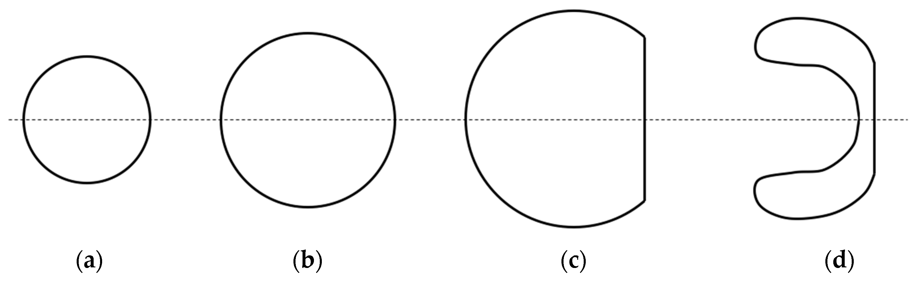
BEM, also known as BIM (Boundary Integral Method), discretizes only the edges of the control volumes formed by a grid. Due to this grid simplicity, BEM allows the calculation of more complex integral equations with a reduced computational power, potentially resulting in highly accurate outputs. It is particularly popular to model problems involving bubble impact, as it provides efficient algorithms to represent its transient shape and pressure from the moment of the explosion until the collapse. Wang et al. [60] proposed numerical modifications to include not only the compressibility over the bubble to simulate its damped oscillation, but also the effect of oscillation cycles subsequent to the first one before it breaks down into smaller bubbles. Zhang et al. [61] introduced improvements to the regular 3D BEM model, enhancing the accuracy and stability at large deformations of the toroidal bubble phase. Li et al. [62] studied the pressure field caused by a collapsing bubble by the auxiliary function method, finding out that its dynamic total pressure can be decomposed and quantified in two parts: one regarding the pressure gradient between the gas within the bubble and surrounding liquid, and another related to its motion. Coupled approaches have also been explored for hydrodynamic problems, such as RANS-BEM (Reynolds-averaged Navier-Stokes) [20] and BEM-FEM. For example, the latter, as studied by Gong et al. [19], allowed the simultaneous simulation of the physics of bubble growth, contraction, and collapse, and the consequent behavior of the hull. The shape transformation of the bubble from its generation until impact, as generically represented in these studies, is displayed in Figure 6.
However, the discretization of a domain in elements might lead to difficulties to deal with free-surfaces, deformable boundaries, moving interfaces, and large fluid deformations, and assuring a satisfactory mesh quality may often be a tricky and time-consuming process. Within this context, Lagrangian based methods, such as SPH, present an interesting alternative to overcome the barriers imposed by a grid system [64]. SPH is a robust method for intricate hydrodynamic problems [46] that represents a set of particles with material properties that interact with each other in the flow. This method is attributed to numerical simulations, in which the analysis deals with large deformations, given that it has a meshless nature. Zhang et al. [52] applied SPH to simulate a charge detonation, the metal-jet formation, and the penetration on a steel plate, agreeing with experimental results. Although impacts on the air-water interface constitute a limitation of the SPH-FEM coupling because of its instabilities in modelling particular water physics [65], it is a valid and precise approach for UNDEX. Ming et al. [18] demonstrated through the comparison of experiments using SPH and SPH-FEM methods that both are accurate to reproduce UNDEX. De Vuyst et al. [66] have actually proved through coupled SPH-FEM simulations the interesting concept that considering the case of having either one or multiple underwater explosions for a same charge quantity, the latter is less harmful to the steel than the first, as it generally results in smaller final deformation and might avoid cracks that could be formed by a single blast.
Given the aforementioned considerable amount of input on numerical modelling techniques, a similar approach to Hirdaris et al. [67] is reflected in Table 1 to summarize the key features of each method addressed in this subsection, aiming to provide a clearer visualization of their particularities. The taxonomy for classification adopted is based on the level of mesh dependency they present to yield accurate outputs, as some methods always include discretization, others partially, and others none.
It is vital to state that a taxonomic descriptive table was preferred to point out the peculiarities of each method, because it is not possible to indicate in a simple manner which method is more appropriate in each occasion; after all, the method choice is subjective for the user, and takes into account their affinity with specific software, the CPU power available, the level of precision requested, and the boundary conditions of the problem to be analyzed. Hence, the same method can present diverse levels of complexity depending on the situation. Besides, through the scientific review hereby carried, it was possible to notice that all methods are capable of providing valid results. Despite this, the survey showed a literature inclination to FEM to reproduce vessel structures, and to BEM and SPH to model the fluids, be they gas (prevenient from bubbles), liquid, or both.
Overcoming the academic sphere, naval classification agencies and official military reports also support these methods, confirming their legitimacy to simulate UNDEX. Holtmann from Det Norske Veritas [59] advises FEM to evaluate the shock resistance, accelerations, strains, and stresses of hull girders for providing a fast and efficient approach. Wang et al. from American Bureau of Shipping make use of nonlinear FEM to design ship structures for ice loads [68]. Warlaw [55] from the U.S. Navy considers the division of the UNDEX simulation domain into FVM cells applied to problems with different dimensions and border conditions. Det Norske Veritas [69] sees BEM as the most common method to solve potential flow problems, whereas O’Daniel et al. [16] from the U.S. Army faces this method as the most suitable to simulate the behavior of bubbles. Also, Jones et al. [70] from the Department of Defense of Australia recognizes SPH as appropriate for modeling several fluid problems of particular military interest.
3.3. Constitutive Models
The techniques used to model impact solicitations differ depending on the type of material considered [71,72,73], and particular sets of equations must be adopted to form a software-embedded constitutive model, which generally requires calibration of variables. Often, given the wide application of metals in shipbuilding, the models used for UNDEX make use of relations developed for metallic materials, which are generally highly dependent on strain rate effects [74].
Accordingly, ship design relies on such resource to properly characterize the vessel itself and all its structural components to efforts intrinsic of navigation, as well as to external input forces such as UNDEX. A variety of studies deal with different strategies to model the aforementioned problem, exhibiting the versatility with which it can be done by using diverse approaches and modeling techniques.
Characterizing a common ground among most authors, the application of the Johnson-Cook constitutive model [75] for the ship hull or single panels is widely utilized, coupled with equations of state in numerical codes, allowing its usage for UNDEX loading. Furthermore, it accounts for equivalent plastic strain, strain rate, and the influence of temperature, while requiring only five parameters that can be found by means of experimental tests, as described in Equation (23):
where is the effective plastic strain, is the same strain but at a reference rate and is the homologous temperature calculated by the quotient of the difference between the material temperature and the room temperature by the difference between the melting temperature and the room temperature. As for the five parameters, namely A, B, C, m, and n, the first two and the latter are obtained from tension tests, while C and m are defined through split Hopkinson pressure bar tests. This model was used by Kong et al. [76], which numerically reproduced a blast load detonated inside a multi-layer protective and stiffened naval structure, demonstrating in this case that stiffened plates are severely damaged by fragments which penetrate, causing diverse spots of crack initiation culminating into crack propagation. On relatable UNDEX studies [18,28], stiffened plates were also modeled, making use of the Johnson-Cook criterion.
Another relevant constitutive model used in this field, although secondary compared to Johnson-Cook’s for being less accurate to represent UNDEX, is Gurson’s [77]. It can be calibrated by the realization of mechanical tests [2] and describes stress flow and rupture of materials depending on void growth. A description of the damage growth rate () as a function of the void volume fraction () and the plastic strain rate () in a pure shear stress case (i.e., in the kk direction) follows (Equation (24)):
In this case, the limitation assumed by this model is that no damage is predicted when strain is under zero mean stress, depending exclusively on the formation of voids. Aiming to address this issue and include the effect of shear-induced fracture also in the absence of voids, a modification of this model was introduced by Nahshon et al. [78], which adds the numerical constant to define the rate of damage evolution in a shear-predominant stress state. The evolution of the model is thus presented by the incorporation of a second term on Equation (24) resulting in Equation (25):
where describes the relation between a third invariant of stress with effective stress [78], is the stress deviator , and stands for the effective stress. This enhanced approach was validated by Xue et al. [79], where the calibration of the damage parameters inherent of this constitutive model were able to reproduce tension and shear induced failures on steel coupons. Latourte et al. [2] used it to numerically describe the behavior of high performance steel alloys to UNDEX.
As for sandwich panels, studies such as the ones from Tilbrook et al. [37,80], considering anisotropic foam cores and elastically ideal skin sheets, provide particular constitutive models allying the mechanics of core compression with the bending response of sandwich beams. These two impulsive load responses can be described in four ways, depending on whether they are analyzed separately (if the accelerations of the sheets differ) or together, and if the core densification is total or partial.
4. Discussion
Addressing the mechanics embraced by underwater explosions, the present survey underlines essential mathematical relations from the hydrodynamics of subsea explosions, to the propagation of high pressure waves and bubbles, to the behavior shown by materials and structures commonly used in shipbuilding. The validity of these methods has been checked through the high correlation of purely analytical formulations with several experimental works, although some discrepancies among authors have also been identified, such as the constants used for determining peak pressure as a function of the charge load.
Likewise, the variety of computational numerical resources applied in this area have permitted the constitution of advanced research studies that are able to mirror UNDEX, conditions considering complex wave force transmission mechanisms and progressively accurate material responses in parallel, thus ratifying the forefront role played by virtual simulations in related engineering problems.
Moreover, the confrontation of the late efforts in improving and perfecting the precise reproducibility of constitutive models to real situations, with the reported advanced material characterization and hydrodynamic studies, show that this traditional but ongoing research field has kept its evolving pace and still presents a remarkable development potential.
Among the possible future directions for this area of study, it is hereby encouraged that a comparative study considering different numerical simulation techniques (such as FVM, BEM, and SPH) is carried, adopting the same boundary conditions, aiming to narrow the current subjectivity in selecting the modelling method to a more grounded approach, crossing desired output accuracy with computational power available. Regarding the analytical side, it would be considerably relevant if new experimental studies could confront the response of materials for hull panels to UNDEX to those in the sometimes-conflicting studies available in the literature. In this case, special attention should be given to fiber reinforced composite materials for their growing importance in the nautical industry over the past years, considering their behavior to underwater explosions has not yet been properly explored.
Funding
This research received no external funding.
Conflicts of Interest
The author declares no conflict of interest.
References
- Pedersen, P.T.; Zhang, S. On impact mechanics in ship collisions. Mar. Struct. 1998, 11, 429–449. [Google Scholar] [CrossRef]
- Latourte, F.; Wei, X.; Feinberg, Z.D.; De Vaucorbeil, A.; Tran, P.; Olson, G.B.; Espinosa, H.D. Design and identification of high performance steel alloys for structures subjected to underwater impulsive loading. Int. J. Solids Struct. 2012, 49, 1573–1587. [Google Scholar] [CrossRef] [Green Version]
- Fragassa, C.; Minak, G. Measuring Deformations in a Rigid-Hulled Inflatable Boat. Key Eng. Mater. 2017, 754, 295–298. [Google Scholar] [CrossRef]
- Liang, Y.; Spuskanyuk, A.V.; Flores, S.E.; Hayhurst, D.R.; Hutchinson, J.W.; McMeeking, R.M.; Evans, A.G. The response of metallic sandwich panels to water blast. J. Appl. Mech. 2007, 74, 81–99. [Google Scholar] [CrossRef]
- Fragassa, C. From Design to Production: An integrated advanced methodology to speed up the industrialization of wooden boats. J. Ship Prod. Des. 2017, 33, 237–246. [Google Scholar] [CrossRef]
- Fragassa, C. Marine Applications of Natural Fibre-Reinforced Composites: A Manufacturing Case Study. In Advances in Application of Industrial Biomaterials; Pellicer, E., Nikolic, D., Sort, J., Baró, M., Zivic, F., Grujovic, N., Grujic, R., Pelemis, S., Eds.; Springer International Publishing: Cham, Switzerland, 2017; pp. 21–47. ISBN 978-3-319-62766-3. [Google Scholar]
- Lorenzini, G.; Helbig, D.; Real, M.V.; Dos Santos, E.D.; Isoldi, L.A.; Rocha, L.A.O. Computational modeling and constructal design method applied to the mechanical behavior improvement of thin perforated steel plates subject to buckling. J. Eng. Thermophys. 2016, 25, 197–215. [Google Scholar] [CrossRef]
- Lorenzini, G.; Helbig, D.; Da Silva, C.C.C.; Real, M.V.; Dos Santos, E.D.; Isoldi, L.A.; Rocha, L.A.O. Numerical evaluation of the effect of type and shape of perforations on the buckling of thin steel plates by means of the constructal design method. Heat Tech. 2016, 34, S9–S20. [Google Scholar] [CrossRef]
- Helbig, D.; Da Silva, C.C.C.; Real, M.V.; Dos Santos, E.D.; Isoldi, L.A.; Rocha, L.A.O. Study About Buckling Phenomenon in Perforated Thin Steel Plates Employing Computational Modeling and Constructal Design Method. Latin Am. J. Solids Struct. 2016, 13, 1912–1936. [Google Scholar] [CrossRef] [Green Version]
- Keil, A.H.; UERD, Norfolk Naval Ship Yard, Portsmouth, VA, USA. Introduction to underwater explosion research, 1956.
- Johnson, W.; Poyton, A.; Singh, H.; Travis, F.W. Experiments in the underwater explosion stretch forming of clamped circular blanks. Int. J. Mech. Sci. 1966, 8, 237–270. [Google Scholar] [CrossRef]
- Strahle, W.C.; Georgia Institute of Technology, Atlanta, GA, USA. Investigation of research needs for underwater explosions, 1990.
- Barash, R.M.; United States Naval Ordnance Laboratory, White Oak, MD, USA. Underwater explosions beneath ice, 1962.
- Bryant, E.F.; Malaker Laboratories Inc., High Brigde, NJ, USA. Debris distribution in underwater explosions, 1964.
- Snay, H.G.; United States Naval Ordnance Laboratory, White Oak, MD, USA. Hydrodynamic concepts selected topics for underwater nuclear explosions, 1966.
- O’Daniel, J.L.; Harris, G.; Ilamni, R.; Chahine, G.; Fortune, J. Underwater Explosion Bubble Jetting Effects on Infrastructure; US Army Corps of Engineers—ERDC Vicksburg: Vicksburg, MS, USA, 2011. [Google Scholar]
- Miller, W.E. Simulation of the Underwater Nuclear Explosion and Its Effects. Ph.D. Thesis, Naval Postgraduate School, Monterey, CA, USA, June 1992. [Google Scholar]
- Ming, F.R.; Zhang, A.M.; Xue, Y.Z.; Wang, S.P. Damage characteristics of ship structures subjected to shockwaves of underwater contact explosions. Ocean Eng. 2016, 117, 359–382. [Google Scholar] [CrossRef]
- Gong, S.W.; Khoo, B.C. Transient response of stiffened composite submersible hull to underwater explosion bubble. Compos. Struct. 2015, 122, 229–238. [Google Scholar] [CrossRef]
- Regener, P.B.; Mirsadraee, Y.; Andersen, P. Nominal vs. Effective Wake Fields and their Influence on Propeller Cavitation Performance. J. Mar. Sci. Eng. 2018, 6, 34. [Google Scholar] [CrossRef]
- Brenner, M. Navy Ship Underwater Shock Prediction and Testing Capability Study; Report-No. JSR, 07-200; MITRE Corporation: McLean, VA, USA, 2007. [Google Scholar]
- De Vuyst, T.; Vignjevic, R.; Albero, A.A.; Hughes, K.; Campbell, J.C.; Djordjevic, N. The effect of the orientation of cubical projectiles on the ballistic limit and failure mode of AA2024-T351 sheets. Int. J. Impact Eng. 2017, 104, 21–37. [Google Scholar] [CrossRef]
- Cole, R.H.; Weller, R. Underwater explosions. Phys. Today 1948, 1, 35. [Google Scholar] [CrossRef]
- Cui, P.; Zhang, A.M.; Wang, S.P. Small-charge underwater explosion bubble experiments under various boundary conditions. Phys. Fluids 2016, 28, 117103. [Google Scholar] [CrossRef]
- Zamyshlyayev, B.V.; Yakovlev, Y.S. Dynamic Loads in Underwater Explosion; Naval Intelligence Support Center: Washington, DC, USA, 1973. [Google Scholar]
- Keil, A.H. The Response of Ships to Underwater Explosions; Report No. DTMB-1576; David Taylor Model Basin: Washington, DC, USA, 1961.
- Rajendran, R.; Narasimhan, K. Deformation and fracture behaviour of plate specimens subjected to underwater explosion—A review. Int. J. Impact Eng. 2006, 32, 1945–1963. [Google Scholar] [CrossRef]
- Gupta, N.K.; Kumar, P.; Hegde, S. On deformation and tearing of stiffened and un-stiffened square plates subjected to underwater explosion—A numerical study. Int. J. Mech. Sci. 2010, 52, 733–744. [Google Scholar] [CrossRef]
- Rajendran, R.; Paik, J.K.; Kim, B.J. Design of warship plates against underwater explosions. Ships Offshore Struct. 2006, 1, 347–356. [Google Scholar] [CrossRef]
- Hung, C.F.; Lin, B.J.; Hwang-Fuu, J.J.; Hsu, P.Y. Dynamic response of cylindrical shell structures subjected to underwater explosion. Ocean Eng. 2009, 36, 564–577. [Google Scholar] [CrossRef]
- Prusty, B.G.; Satsangi, S.K. Analysis of stiffened shell for ships and ocean structures by finite element method. Ocean Eng. 2001, 28, 621–638. [Google Scholar] [CrossRef]
- Gordo, J.M.; Soares, C.G.; Faulkner, D. Approximate assessment of the ultimate longitudinal strength of the hull girder. J. Ship Res. 1996, 40, 60–69. [Google Scholar]
- Gordo, J.M.; Soares, C.G. Approximate load shortening curves for stiffened plates under uniaxial compression. Integr. Offshore Struct. 1993, 5, 189–211. [Google Scholar]
- Chen, Y.; Tong, Z.P.; Hua, H.X.; Wang, Y.; Gou, H.Y. Experimental investigation on the dynamic response of scaled ship model with rubber sandwich coatings subjected to underwater explosion. Int. J. Impact Eng. 2009, 36, 318–328. [Google Scholar] [CrossRef]
- Watson, D.G.M. Practical Ship Design; Elsevier: Amsterdam, The Netherlands, 1998; Volume 1, ISBN 978-0-0804-2999-1. [Google Scholar]
- Tupper, E.C.; Rawson, K.J. Basic Ship Theory; Butterworth-Heinemann: Oxford, UK, 2001; Volume 2, ISBN 978-0-7506-5398-5. [Google Scholar]
- Tilbrook, M.T.; Deshpande, V.S.; Fleck, N.A. Underwater blast loading of sandwich beams: Regimes of behaviour. Int. J. Solids Struct. 2009, 46, 3209–3221. [Google Scholar] [CrossRef] [Green Version]
- Fleck, N.A.; Deshpande, V.S. The resistance of clamped sandwich beams to shock loading. J. Appl. Mech. 2004, 71, 386–401. [Google Scholar] [CrossRef]
- Hutchinson, J.W.; Xue, Z. Metal sandwich plates optimized for pressure impulses. Int. J. Mech. Sci. 2005, 47, 545–569. [Google Scholar] [CrossRef]
- Fan, Z.; Liu, Y.; Xu, P. Blast resistance of metallic sandwich panels subjected to proximity underwater explosion. Int. J. Impact Eng. 2016, 93, 128–135. [Google Scholar] [CrossRef]
- Rajendran, R.; Narasimhan, K. Linear elastic shock response of plane plates subjected to underwater explosion. Int. J. Impact Eng. 2001, 25, 493–506. [Google Scholar] [CrossRef] [Green Version]
- Rajendran, R.; Narasimhan, K. Underwater shock response of circular HSLA steel plates. Shock Vibr. 2000, 7, 251–262. [Google Scholar] [CrossRef]
- Rajendran, R.; Narasimhan, K. Damage prediction of clamped circular plates subjected to contact underwater explosion. Int. J. Impact Eng. 2001, 25, 373–386. [Google Scholar] [CrossRef] [Green Version]
- Jones, N. Structural Impact, 2nd ed.; Cambridge University Press: Cambridge, UK, 2012; ISBN 978-1-1070-1096-3. [Google Scholar]
- Jacob, N.; Yuen, S.C.K.; Nurick, G.N.; Bonorchis, D.; Desai, S.A.; Tait, D. Scaling aspects of quadrangular plates subjected to localised blast loads—Experiments and predictions. Int. J. Imp. Eng. 2004, 30, 1179–1208. [Google Scholar] [CrossRef]
- Zhang, A.M.; Sun, P.N.; Ming, F.R.; Colagrossi, A. Smoothed particle hydrodynamics and its applications in fluid-structure interactions. J. Hydrodyn. 2017, 29, 187–216. [Google Scholar] [CrossRef]
- Helenbrook, B.T.; Hrdina, J. High-order adaptive arbitrary-Lagrangian–Eulerian (ALE) simulations of solidification. Comput. Fluids 2018, 167, 40–50. [Google Scholar] [CrossRef]
- Wang, G.; Wang, Y.; Lu, W.; Zhou, W.; Chen, M.; Yan, P. On the determination of the mesh size for numerical simulations of shock wave propagation in near field underwater explosion. Appl. Ocean Res. 2016, 59, 1–9. [Google Scholar] [CrossRef]
- Liu, W.T.; Ming, F.R.; Zhang, A.M.; Miao, X.H.; Liu, Y.L. Continuous simulation of the whole process of underwater explosion based on Eulerian finite element approach. Appl. Ocean Res. 2018, 80, 125–135. [Google Scholar] [CrossRef]
- Hu, X.Y.; Adams, N.A.; Iaccarino, G. On the HLLC Riemann solver for interface interaction in compressible multi-fluid flow. J. Comput. Phys. 2009, 228, 6572–6589. [Google Scholar] [CrossRef]
- Ma, Z.H.; Causon, D.M.; Qian, L.; Gu, H.B.; Mingham, C.G.; Ferrer, P.M. A GPU based compressible multiphase hydrocode for modelling violent hydrodynamic impact problems. Comput. Fluids 2015, 120, 1–23. [Google Scholar] [CrossRef]
- Zhang, Z.; Wang, L.; Silberschmidt, V.V. Damage response of steel plate to underwater explosion: Effect of shaped charge liner. Int. J. Impact Eng. 2017, 103, 38–49. [Google Scholar] [CrossRef] [Green Version]
- Jafarian, A.; Pishevar, A. An exact multiphase Riemann solver for compressible cavitating flows. Int. J. Multiphase Flow 2017, 88, 152–166. [Google Scholar] [CrossRef]
- Petrov, N.V.; Schmidt, A.A. Multiphase phenomena in underwater explosion. Exp. Therm. Fluid Sci. 2015, 60, 367–373. [Google Scholar] [CrossRef]
- Wardlaw, A.B., Jr. Underwater Explosion Test Cases; No. NSWC-IHTR-2069; Naval Surface Warfare Center: Indian Head, MD, USA, 1998. [Google Scholar]
- Rigo, P.; Rizzuto, E. Analysis and Design of Ship Structure. Ship Des. Constr. 2003, 1, 18-1. [Google Scholar]
- Zhang, W.; Yao, X.; Liu, L.; Wang, Z. Semi-analytical and experimental investigation of the whipping response of a cylinder subjected to underwater explosion load. Ships Offshore Struct. 2018, 1–9. [Google Scholar] [CrossRef]
- Chung, J.; Shin, Y.S. Simulation of dynamic behaviour of high-speed catamaran craft subjected to underwater explosion. Ships Offshore Struct. 2013, 9, 387–403. [Google Scholar] [CrossRef]
- Det Norske Veritas. Available online: https://www.dnvgl.com/services/shock-analysis-4716 (accessed on 30 November 2018).
- Wang, Q. Multi-oscillations of a bubble in a compressible liquid near a rigid boundary. J. Fluid Mech. 2014, 745, 509–536. [Google Scholar] [CrossRef]
- Zhang, A.M.; Liu, Y.L. Improved three-dimensional bubble dynamics model based on boundary element method. J. Comput. Phys. 2015, 294, 208–223. [Google Scholar] [CrossRef]
- Li, S.; Han, R.; Zhang, A.M.; Wang, Q.X. Analysis of pressure field generated by a collapsing bubble. Ocean Eng. 2016, 117, 22–38. [Google Scholar] [CrossRef]
- Maljaars, P.; Kaminski, M.; den Besten, H. Boundary element modelling aspects for the hydro-elastic analysis of flexible marine propellers. J. Mar. Sci. Eng. 2018, 6, 67. [Google Scholar] [CrossRef]
- Liu, M.B.; Liu, G.R. Smoothed particle hydrodynamics (SPH): An overview and recent developments. Arch. Comput. Methods Eng. 2010, 17, 25–76. [Google Scholar] [CrossRef]
- Hughes, K.; Vignjevic, R.; Campbell, J.; De Vuyst, T.; Djordjevic, N.; Papagiannis, L. From aerospace to offshore: Bridging the numerical simulation gaps–Simulation advancements for fluid structure interaction problems. Int. J. Impact Eng. 2013, 61, 48–63. [Google Scholar] [CrossRef]
- De Vuyst, T.; Kong, K.; Djordjevic, N.; Vignjevic, R.; Campbell, J.C.; Hughes, K. Numerical modelling of the effect of using multi-explosives on the explosive forming of steel cones. J. Phys. Conf. Ser. 2016, 734, 032074. [Google Scholar] [CrossRef]
- Hirdaris, S.E.; Lee, Y.; Mortola, G.; Incecik, A.; Turan, O.; Hong, S.Y.; Kim, B.W.; Kim, K.H.; Bennett, S.; Miao, S.H.; et al. The influence of nonlinearities on the symmetric hydrodynamic response of a 10,000 TEU Container ship. Ocean Eng. 2016, 111, 166–178. [Google Scholar] [CrossRef] [Green Version]
- Wang, G.; Wiernicki, C.J. Using nonlinear finite element method to design ship structures for ice loads. Mar. Tech. 2006, 43, 1–15. [Google Scholar]
- Det Norske Veritas. Recommended Practice DNV-RP-C205: Environmental Conditions and Environmental Loads; Det Norske Veritas: Hovik, Norway, 2014. [Google Scholar]
- Jones, D.A.; Belton, D. Smoothed Particle Hydrodynamics: Applications within DSTO (No. DSTO-TR-1922); Defence Sci. Tech. Org.; Platform Sciences Lab: Fishermans Bend, Victoria, Australia, 2006. [Google Scholar]
- Fragassa, C.; Camargo, F.V.; Pavlovic, A.; Minak, G. Explicit numerical modeling assessment of basalt reinforced composites for low-velocity impact. Comp. Part B: Eng. 2019, in press. [Google Scholar] [CrossRef]
- Pavlovic, A.; Camargo, F.V.; Fragassa, C. Crash safety design: Basic principles of impact numerical simulations for composite materials. In Proceedings of the 9th International Conference on Times of Polymers and Composites (AIP Conference Proceedings), Ischia, Italy, 17–21 June 2018; D’Amore, A., Grassia, L., Acierno, D., Eds.; AIP Publishing: Melville, NY, USA, 2018; Volume 1981, p. 020032. [Google Scholar] [CrossRef]
- Fragassa, C.; Camargo, F.V.; Pavlovic, A.; Silveira, A.C.F.; Minak, G.; Bergmann, C.P. Mechanical Characterization of Gres Porcelain and Low-Velocity Impact Numerical Modelling. Materials 2018, 11, 1082. [Google Scholar] [CrossRef] [PubMed]
- Djordjevic, N.; Vignjevic, R.; Kiely, L.; Case, S.; De Vuyst, T.; Campbell, J.; Hughes, K. Modelling of shock waves in fcc and bcc metals using a combined continuum and dislocation kinetic approach. Int. J. Plast. 2018, 105, 211–224. [Google Scholar] [CrossRef]
- Johnson, G.R.; Cook, W.H. A constitutive model and data for metals subjected to large strain, high strain rates and high temperatures. In Proceedings of the 7th International Symposium on Ballistics, The Hague, The Netherlands, 19–21 April 1983; pp. 541–547. [Google Scholar]
- Kong, X.S.; Wu, W.G.; Li, J.; Chen, P.; Liu, F. Experimental and numerical investigation on a multi-layer protective structure under the synergistic effect of blast and fragment loadings. Int. J. Impact Eng. 2014, 65, 146–162. [Google Scholar] [CrossRef]
- Gurson, A.L. Continuum theory of ductile rupture by void nucleation and growth: Part I—Yield criteria and flow rules for porous ductile media. J. Eng. Mat. Tech. 1977, 99, 2–15. [Google Scholar] [CrossRef]
- Nahshon, K.; Hutchinson, J.W. Modification of the Gurson model for shear failure. Eur. J. Mech. A/Solids 2008, 27, 1–17. [Google Scholar] [CrossRef]
- Xue, Z.; Pontin, M.G.; Zok, F.W.; Hutchinson, J.W. Calibration procedures for a computational model of ductile fracture. Eng. Fract. Mech. 2010, 77, 492–509. [Google Scholar] [CrossRef] [Green Version]
- Tilbrook, M.T.; Deshpande, V.S.; Fleck, N.A. Regimes of response for impulse loaded sandwich panels. J. Mech. Phys. Solids 2006, 54, 2242–2280. [Google Scholar] [CrossRef]
Figure 1.
Flow chart scheme of UNDEX aspects approached in the present work.

Figure 2.
Successive underwater wave impacts from the explosion load (W) and incident pressure decay.
Figure 2.
Successive underwater wave impacts from the explosion load (W) and incident pressure decay.

Figure 3.
Failure steps of bulging (a), discing (b), and petaling (c) for metallic square coupons when subjected to underwater explosion tests.
Figure 3.
Failure steps of bulging (a), discing (b), and petaling (c) for metallic square coupons when subjected to underwater explosion tests.

Figure 4.
Geometrical relation during bulging.

Figure 5.
Representation of stress-strain behavior of metals when acknowledging the effect of strain rate.
Figure 5.
Representation of stress-strain behavior of metals when acknowledging the effect of strain rate.
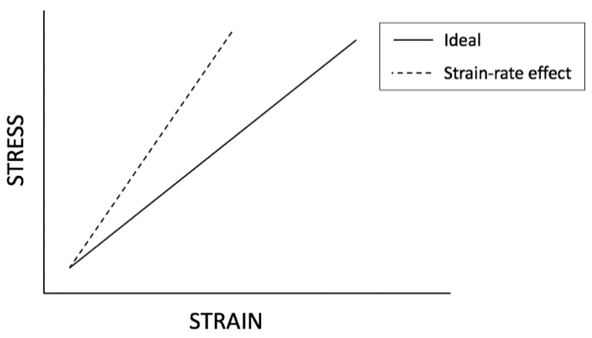
Figure 6.
Representation of steps of bubble mid-sectional shape change starting from its conception (a), expansion due to increase in inner gas pressure (b), flattening on rigid surface and attainment of maximum volume (c), to the collapsing toroidal shape (d).
Figure 6.
Representation of steps of bubble mid-sectional shape change starting from its conception (a), expansion due to increase in inner gas pressure (b), flattening on rigid surface and attainment of maximum volume (c), to the collapsing toroidal shape (d).

Table 1.
Taxonomy of hydrodynamic modelling methods as a function of their discretization dependency.
Table 1.
Taxonomy of hydrodynamic modelling methods as a function of their discretization dependency.
| Level | Method | Key Features | References |
|---|---|---|---|
| 1 | FEM |
| Latourte et al. [2] Gupta et al. [28] Hung et al. [30] Prusty et al. [31] Tillbrook et al. [37] Holtmann et al. [59] Wang et al. [68] |
| 2 | FVM |
| Wang et al. [48] Ma et al. [51] Wardlaw [55] Rigo et al. [56] |
| 3 | BEM |
| O’Daniel et al. [16] Gong et al. [19] Wang [60] Zhang et al. [61] Li et al. [62] DNV [69] |
| 4 | SPH |
| Ming et al. [18] Zhang et al. [46] Zhang et al. [52] Liu et al. [64] Hughes et al. [65] De Vuyst et al. [66] Jones et al. [70] |
© 2019 by the author. Licensee MDPI, Basel, Switzerland. This article is an open access article distributed under the terms and conditions of the Creative Commons Attribution (CC BY) license (http://creativecommons.org/licenses/by/4.0/).
Share and Cite
MDPI and ACS Style
Vannucchi de Camargo, F. Survey on Experimental and Numerical Approaches to Model Underwater Explosions. J. Mar. Sci. Eng. 2019, 7, 15. https://doi.org/10.3390/jmse7010015
AMA Style
Vannucchi de Camargo F. Survey on Experimental and Numerical Approaches to Model Underwater Explosions. Journal of Marine Science and Engineering. 2019; 7(1):15. https://doi.org/10.3390/jmse7010015
Chicago/Turabian StyleVannucchi de Camargo, Felipe. 2019. "Survey on Experimental and Numerical Approaches to Model Underwater Explosions" Journal of Marine Science and Engineering 7, no. 1: 15. https://doi.org/10.3390/jmse7010015
Note that from the first issue of 2016, this journal uses article numbers instead of page numbers. See further details here.