1. Introduction
Steel plates are structural components that are resistant to mechanical loads and used in several sectors of engineering—from the construction of bridges and buildings to airplanes and vessels. In the naval sector, for example, a great number of these structures are required to resist the extremely high loads that arise either because of the weight of their own structure or the sea conditions faced during navigation [
1].
Due to the aforementioned high loadings, these structures must be extremely resistant, particularly to shear stresses and bending moments. Adding more material can increase their strength, although it also increases the weight of the structure, which should be avoided, especially when developing projects for the offshore [
2] and naval [
1] industries. In this context, the application of mechanical stiffeners arises. These stiffeners are long structural profiles fixed to the plates in the horizontal, transverse, or both horizontal and transverse directions. They are employed to improve the rigidity of the structural components that are made out of thin plates.
The structural analysis of stiffened plates has been the focus of countless studies. In [
3], the restrictions method in statistical analysis was applied, via finite elements, to stiffened plates with concentric and eccentric stiffeners. Reference [
4] studied stiffened plates under transversal loading using the sequential quadratic programming method, supposing the structure as a plate firmly connected to stiff beams and minimizing the total energy of the system. In [
5] was utilized a methodology that considered the stresses and the deformations on the plate’s plane, as well as the axial stresses and the deformations on the beams. These stresses were evaluated at the interface between the plates and the stiffeners, and the solution of the differential equations was obtained through the analog equation method (AEM).
More recently, reference [
6] presented numerical studies regarding ribbed floor slabs, indicating that the consideration of eccentricity between the plate and the reinforcement beam results in a reduction in structure displacement. The steel or concrete slabs were simulated with the software ANSYS
®, using shell elements (SHELL63) for modeling the plate and beam elements (BEAM44) for the stiffeners. Moreover, from [
7], four computational models for stiffened plates using the finite element SHELL93 (triangular and quadrilateral) and SOLID95 (tetrahedral and hexahedral), also by means of the software ANSYS
®, were suggested. All the models were verified by comparing their results with the ones obtained by other authors used as a reference.
The present article investigated different geometrical configurations that aimed at increasing the structural rigidity of stiffened plates without adding material that would result, consequently, in heavier structures. In doing so, a steel non-stiffened plate with a determined volume was adopted as a reference. Using the constructal design method, part of the steel volume was converted to stiffeners due to the parameter stiffeners volume fraction (
). The constructal design method was developed based on the constructal law, which states: “For a finite-size flow system to persist in time (to survive), its configuration must evolve in such a way that it provides easier access to the currents that flow through it” [
8]. In practical terms, the constructal design method is based on objectives and restrictions [
9]. In the geometrical evaluation of a given physical system, it is necessary and sufficient to define at least one objective (a performance parameter to be improved), the degrees of freedom (variables), and the geometrical restrictions (fixed parameters). The degrees of freedom are free to vary, but it should respect the imposed constraints [
10].
It is noteworthy that the total volume of steel was kept constant and equal to the volume of the reference plate. Thereby, several different geometrical configurations of stiffened plates were established by means of varying the following degrees of freedom: number of longitudinal stiffeners (Nls), number of transverse stiffeners (Nts), and the ratio between the height and the thickness of the stiffeners (hs/ts). The mechanical behavior of the plates was numerically simulated, considering them as simply supported and subjected to a transverse and uniformly distributed load (pressure), aiming to reproduce a practical situation of a part of a ship deck or offshore oil platform deck. The software ANSYS Mechanical APDL®, which is based on the finite element method (FEM), was utilized to perform the simulations. Thus, the numerical results for the central deflection of the different proposed plates were compared to each other through the exhaustive search technique, allowing the geometrical configuration that would lead to a superior mechanical performance regarding the deflections to be determined.
2. Computational Modeling
Problems involving thin plates without stiffeners are difficult to solve because they involve a fourth order differential equation [
11]. Concerning stiffened plates, an analytical solution becomes practically unreachable, especially when the intent of the research involves the evaluation of a great number of scenarios. Thus, to develop this work, it was decided to use the software ANSYS Mechanical APDL
® (version 14.0, ESSS, Canonsburg, PA, USA), which applies the finite element method (FEM) to successfully solve several kinds of problems from structural [
12] to heat transfer [
13], and embraces all types of materials from composites [
14,
15,
16] to concrete [
17] and ceramics [
18].
Two computational models were developed, one for the non-stiffened plate (used for simulating the reference plate, with no stiffeners) and the other for stiffened plates (used to simulate the geometrical configurations proposed by the constructal design method). In both models, the finite element SHELL93 with a regular quadrilateral mesh was adopted because it is the one indicated for problems involving thin plates and curved shells and it has produced suitable results in similar research [
6,
19,
20]. The Sparse Matrix Direct Solver was employed in both computational models. This numerical method is based on a direct elimination of equations by means of the factorization of an initially very sparse linear system of equations into a lower triangular matrix followed by forward and backward substitution using this triangular system [
21].
To ensure that the computational model is according to the reality that it is meant to simulate, it is possible to validate or verify it. The validation procedure was based on a comparison between the results obtained by the numerical model and laboratory experiments [
7,
10]. The verification procedure consisted of confronting the generated numerical results with the numerical results obtained by other authors and/or with values of analytical resolutions [
11].
It was also important to perform the mesh convergence study, which determines the minimum refinement that provides a numerical result sufficiently accurate. Hence, numerical simulations with successive refinements were performed until there was no significant difference between the obtained results from meshes with successive refinements, defining, thus, the discretization that provides an independent numerical solution. Therefore, all the results achieved in this research were obtained using converged meshes, which exhibited a relative difference of less than 0.15% between the results of consecutive refinements according to the criteria established in this work.
2.1. Verification of the Computational Model for the Non-Stiffened Plate
Concerning the model of the non-stiffened plate, the verification process occurred through a comparison of its results with the ones acquired by numerical studies of [
5,
6] and with the analytical solution of [
22]. In this case, the dimensions of the plate were defined according to
Figure 1, while the material of the plate presented a Young’s modulus (
E) and Poisson’s ratio (
ν) of 30 GPa and 0.154, respectively, characterizing a concrete slab. The boundary conditions were established as simple, supported edges and a pressure of 10 kPa was applied in the negative
z-direction (see
Figure 1).
Figure 2 presents the results obtained by the references, as well as the computational results generated in the present work.
From
Figure 2, it can be noticed that the values of the central deflection
w from the developed model converge closely with the ones attained by references [
5,
6,
22] as the number of finite elements during the mesh convergence study increased. The present work presented differences of 2.50%, 1.86%, and 1.23% when compared with the results of [
5,
6,
22], respectively. Therefore, it is possible to state that this model has been properly verified.
2.2. Verification of the Computational Model for the Stiffened Plate
Similarly, the model for the stiffened plates was verified by comparing its values of central deflection to the ones obtained by the numerical research executed by [
3,
4,
6,
7]. The stiffened plate was considered as simply supported, having a constant pressure of 68.95 kPa applied in the negative
z-direction on its surface without stiffeners (see
Figure 3). The material of the plate and the stiffeners was steel with
E and
ν of 206.84 GPa and 0.3, respectively.
According to
Figure 4, as a result of the mesh convergence study, the values achieved by the developed computational model converge narrowly with the ones found in [
7]. However, they are not similar to the values found by the other authors. Differences of 26.95%, 40.26%, and 30.55% were found when comparing the results of the present work with those obtained by [
3,
4,
6], respectively. As reported by [
7], this difference is due to the fact that a less accurate finite element than the SHELL93 was employed, such as in [
6], which used the SHELL63 finite element for the plate. Besides, the mesh used by these older studies [
3,
4,
6] was likely too coarse. However, when the numerical result of the present study was compared with the result of [
7], which was obtained with a more accurate 3D SOLID95 finite element, a difference of only 2.52% was achieved. Thus, for the reasons explained here, it can be considered that the computational model developed for stiffened plates has been properly verified, despite the divergence found with the studies performed by [
3,
4,
6].
3. Constructal Design Method
In the present work, the constructal design method application enabled defining a set of stiffened plates with various geometric configurations that were numerically simulated and compared through the exhaustive search technique. To do so, the dimensions of a non-stiffened plate to be used as a reference were defined: length a = 2000 mm, width b = 1000 mm, and thickness t = 20 mm.
All geometric configurations of the stiffened plates were formed from the reference plate. The stiffened plate had the same in-plane dimensions as the reference plate, i.e., the length
a and the width
b were kept constant. However, a portion of the reference plate material was transformed into stiffeners by reducing its thickness
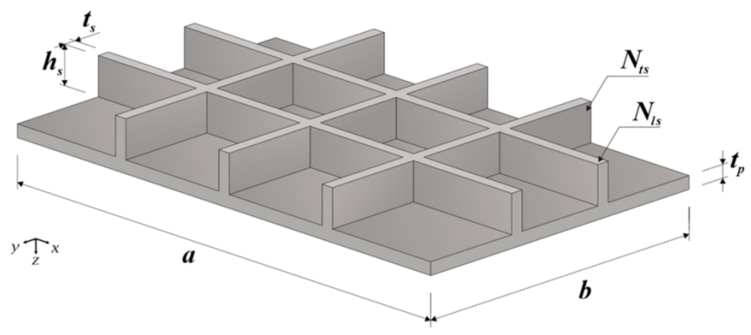
t. The ratio between the volume of the reference plate and the volume of material employed as stiffeners, called stiffeners volume fraction, is defined by:
where
Vs is the volume of the reference plate transformed into stiffeners;
Vr is the total volume of the plate used as reference;
Nls and
Nts represent, respectively, the number of longitudinal and transverse stiffeners;
hs and
ts are, respectively, the height and thickness of the stiffeners; and
a,
b, and
tp are, respectively, the length, width, and thickness of the stiffened plate, as indicated in
Figure 5.
In order to accomplish the objective of finding a stiffened plate that presents a minor central deflection, the evaluated degrees of freedom were Nls, Nts, and hs/ts; while the imposed restrictions were that all stiffened plates have the same material volume, length, and width as the reference plate. Furthermore, since the present work adopted only one value of (which was defined as 0.4), it became an additional geometrical restriction of the analysis. In other words, 40% of the volume of the reference plate was turned into stiffeners of different configurations and geometries, due to the variation of the degrees of freedom Nls, Nts, and hs/ts. In addition, values of Nls and Nts were adopted between 2 to 5; other restrictions due to geometrical limitations of the problem included: hs ≤ 300 mm, avoiding a disproportionality between the height of the stiffeners and the width of the plate; and hs/ts ≥ 1, in order to avoid obtaining stiffeners with heights greater than their thickness, which would over reduce the moment of inertia of these reinforcements. The thickness of the stiffeners was adopted according to standard sizes of steel plates, varying from 3.75 mm (1/8 in) to 75.2 mm (3 in). Furthermore, in all simulations, the applied load conditions were the same—that is, a uniformly distributed transverse loading (pressure) of 10 kPa—aiming to guarantee that all cases studied had a linear-elastic behavior. Similarly, regarding the boundary conditions, all simulated plates were simply supported on all four of their edges. Moreover, the steel used in these structures had a Young’s modulus and Poisson’s ratio of 200 GPa and 0.3, respectively.
Figure 6 depicts the methodological structure used in the definition of the geometrical configurations of the stiffened plates that composed the analyzed search space.
4. Results and Discussion
Following the scheme presented in
Figure 6, various numerical simulations of the stiffened plates were performed (a total of 166 simulations).
The non-stiffened reference plate was numerically simulated using a converged regular mesh with 100 mm quadrilateral shaped elements; a central displacement of 0.698 mm was obtained. The stiffened plates mesh had the same characteristics as the reference plate’s mesh. The central deflection of stiffened plates are shown in
Figure 7 as a function of the degree of freedom
hs/
ts for each geometry studied in this work, following the notation
Nls ×
Nts.
In
Figure 7, one can notice that there is a pattern in the behavior of the stiffened plates, which enabled the central deflection of the plates to be estimated through equations obtained from a nonlinear regression. The coefficient of determination (
R2) of this regression, which is the statistical measure of how well the regression curve matches with the real data, was higher than 0.99 for all combinations of
Nts and
Nls, indicating an excellent fit. The central deflections (in mm) can be obtained through the following equation:
where
α and
β coefficients are dependent on the degrees of freedom, i.e., the number of longitudinal and transverse stiffeners. These coefficients and
R2 are presented in
Table 1 for each combination of
Nts and
Nls analyzed.
From an analysis of the data presented in
Figure 7 and
Table 1, it can be noted that an increment in the ratio
hs/
ts caused a decrease in the central deflection for the stiffened plates. This mechanical behavior can be explained by the fact that the moment of inertia increases due to an increase in
hs/
ts, and consequently so does the plate’s stiffness. However, for values of
hs/
ts ≥ 20, there was no significant reduction in the plate’s central deflection.
Besides, it is possible to observe that the degree of freedom
Nls has more influence on the structural mechanical behavior than
Nts, as the stiffened plates with the same values of
Nls presented similar central displacement when
hs/
ts varied, independently of
Nts. This fact is evidenced by the similarity of the coefficients
α and
β for plates with the same number of longitudinal stiffeners (see
Table 1). Therefore, it is possible to neglect the influence of
Nts on the analysis, enabling an estimation of the central deflection of the plates for each
Nls through the equations obtained from a nonlinear regression, as a function of exclusively the ratio between the height and the thickness of the stiffeners. Therefore, the central out-of-plane displacements of the stiffened plates with
Nls = 2, 3, 4, and 5 can be obtained, respectively, through the following equations:
where
,
,
, and
are the central deflections for the plates with
Nls = 2, 3, 4, and 5, respectively.
Equations (3)–(6) are even more useful for small values of hs/ts where the coefficient that precedes them becomes more relevant. Thus, according to the observed trend, when it was kept constant the total material volume and the ratio hs/ts assumed small values, a shorter number of stiffeners led to a smaller deflection.
From Equations (3)–(6) it is also possible to propose a unique equation to represent these equations, given by:
where coefficient
β = −0.758 is the average value for the
β coefficients of Equations (3) to (6) with a standard deviation of 0.017; the
α coefficient, which was determined as the average value of the ratios
α/
Nls for Equations (3) to (6), is 0.085 (with a standard deviation of 0.004), which should be multiplied by the number of longitudinal
Nls stiffeners in each case.
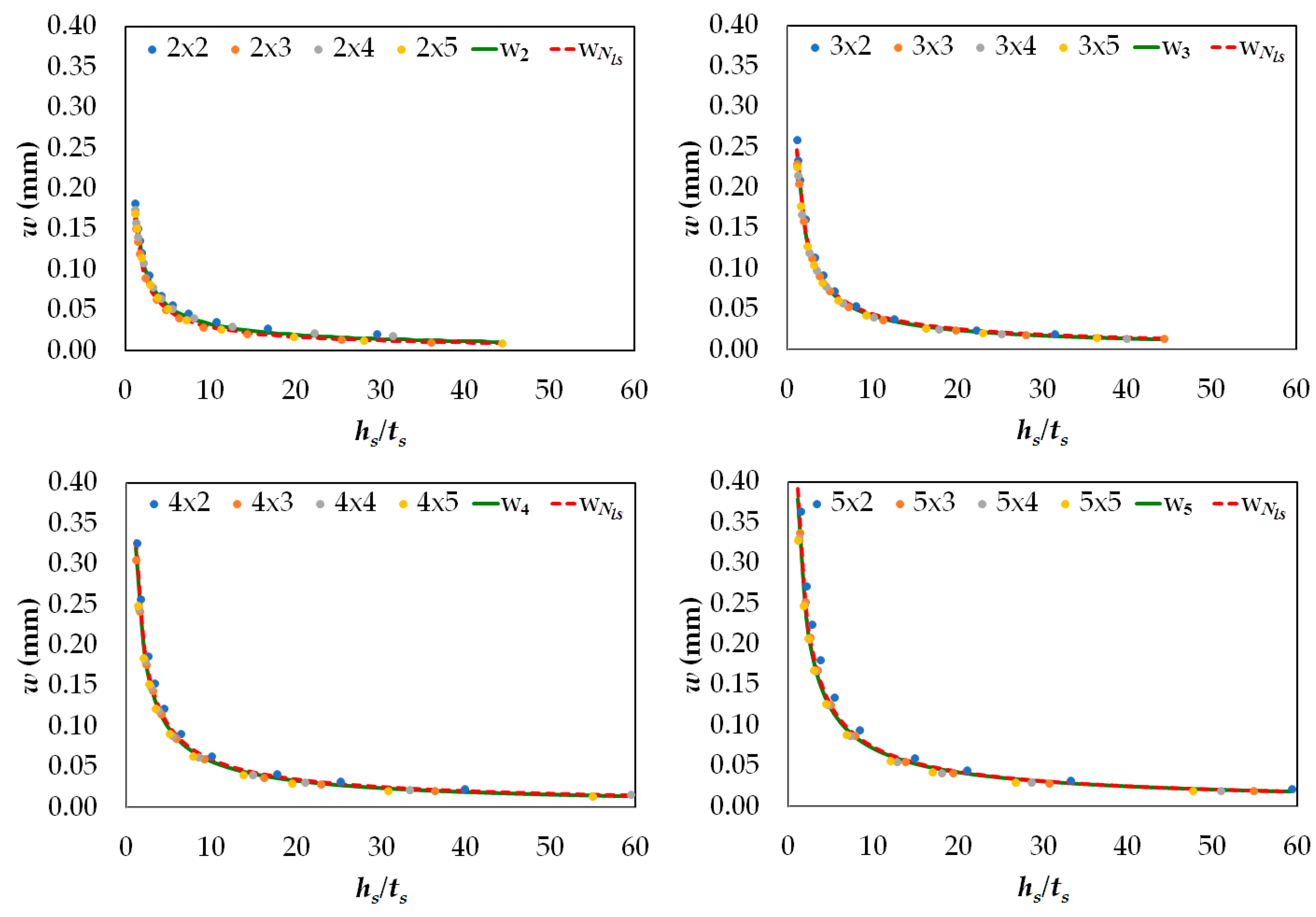
Therefore, to prove the effectiveness of the proposed equations, the numerical results generated in the present work (see
Figure 7) were compared with the analytical results from Equations (3) to (6) and Equation (7), being shown in
Figure 8.
Equations (3)–(6) had
R2 coefficients of 0.9786, 0.9965, 0.9913, and 0.9895, respectively, in relation to the results of the performed numerical simulations, as can be viewed in
Figure 9.
In
Figure 9, one can note the good agreement of Equation (7) (dashed red curve) with Equations (3)–(6) (continuous green curve). Accordingly, if only Equation (7) be adopted to predict the central deflections of the analyzed stiffened plates a good agreement is achieved, being this simplification more attractive for practical design purposes.
It is also important to highlight that when the deflections of the stiffened plates are compared to the reference plate, all of the suggested geometrical configurations of the stiffened plates presented a smaller central deflection than that obtained by the non-stiffened plate with the same steel volume. Even though these are all better results, there is great variation in their values as the parameters changed, varying the reduction of the central deflection from 47.68% to 98.57%. This shows how important this type of analysis is. Also, an increment in the number of stiffeners is not directly related to an increase in the structural rigidity because, in order to keep the same material volume of the structure, a greater number of stiffeners entails a reduction in their height and consequently in the moment of inertia.
Lastly, through a global comparison among all analyzed stiffened plates (see
Figure 7), it was possible to determine the optimal geometric configuration that would lead to the best mechanical behavior, i.e., the geometric configuration that minimizes the central deflection. The minimal central displacement among all studied geometries was 0.00997 mm and was obtained by the plate with
Nls = 2,
Nts = 5, and
hs/
ts = 44.40, which is depicted in
Figure 9a. The optimal stiffened plate’s geometric configuration enabled a reduction of 98.57% in the central deflection if compared to the reference plate.
Figure 9 also shows a comparison between the stiffened plates that led to the optimal (
Figure 9a) and worst (
Figure 9b) geometrical configurations in terms of central deflection. One can observe that in the worst configuration, the stiffened plate had a deformed pattern similar to a plate without stiffeners, i.e., the maximal deflection occurred in the plate’s central point; for the optimized geometry, the stiffeners, mainly due to its
hs/
ts value, promoted a division of the plate into several regions, each behaving like an “unstiffened” small plate. Moreover, it is evident that the magnitude of the deflections was heavily affected by the variation of
hs/
ts,
Nls, and
Nts once the same material quantity was adopted in all cases.
5. Conclusions
In the present work, a structural numerical analysis was performed to estimate the central deflection of thin stiffened plates and the influence of parameters such as the number of longitudinal and transverse stiffeners and the ratio between their height and thickness. To do so, it was kept constant the total volume of the plate.
From the results obtained, as expected, the application of stiffeners in thin plates provided greater rigidity to the structure. All stiffened plates presented central displacements that were smaller than the one presented by the non-stiffened plate used as a reference. Moreover, the importance of performing studies on this subject was shown, since the geometric configuration of the stiffeners had a substantial influence on the deflection values. Wide variations were shown in these values due to modifications in the geometry. It was also noted that for hs/ts values greater than 20, there was no significant reduction in the central deflection of the stiffened plates analyzed.
Furthermore, from the results of this work, it was possible to obtain, through nonlinear regressions, equations that accurately describe the deflection of the studied stiffened plates. From these equations, along with an analysis of the charts, it was observed that the out-of-plane central displacement decreased as the ratio hs/ts increased. In addition, by using these equations, the deflection values could be estimated based exclusively on the ratio between the stiffeners’ heights and thicknesses (hs/ts) for each Nls value. These deflection values were even more useful when this relation assumed small values. In addition, a simple and effective equation was proposed to determine the central deflections of the stiffened plates studied in the present work.
Finally, the global optimized geometric configuration was determined among all analyzed plates, i.e., the stiffened plate geometry that minimized the central deflection. Thus, the optimized geometry was the one that presented two longitudinal stiffeners, five transverse stiffeners, and a ratio hs/ts of 44.40. This geometry enabled a reduction of 98.57% in the central deflection when compared with the non-stiffened reference plate.
In future work, it is recommended to investigate other values of , as well as other types of stiffeners. It would also be interesting to perform a complementary study to this work where not only the central deflection but also the mechanical behavior regarding the stresses be taken into account.


 ,
, 


