Abstract
Rigid-hulled inflatable boats are extremely practical and popular nowadays, offering an effective conciliation among usability and costs. Their stable and seaworthy behavior is guaranteed by performing hydroplaning hulls coupled with unsinkable inflated tubes. At the same time, their design is often based on tradition and preconceptions. In this article, both numerical methods and experimental mechanics techniques are proposed as an essential way for supporting the designers in decisive tasks. Three different situations are detailed where a numerical or an experimental approach shows its benefit inside the engineering design process: firstly, permitting investigation of the behavior of materials driving the fiberglass selection; then measuring the levels of stress and strain in the hull during sailing; and finally, using information as a base for developing numerical models of the hull slamming in waves. Even if the discussion is focused on a rigid inflatable boat, a large part of these considerations is relevant beyond this particular case.
1. Introduction
A rigid-hulled inflatable boat or, in a simpler way, a rigid inflatable boat (RIB), represents a very popular segment of light crafts, offering high performance and additional practical advantages [1]. These crafts demonstrate stability in navigation thanks to specific design solutions pairing a solid and resistant hull with flexible tubes at the gunwale [2]. In addition, the inflatable collar can keep buoyancy even in the case of craft inundation in relation to bad sea conditions [3].
RIBs are generally between 4 and 9 m as length, although, sometimes, they can raise up to 18 m. These boats are often moved by one or more outboard motors with, typically, a power between 4 to 200 kW. RIBs represent a valid sailing solution to an extremely wide range of utilization, able to include special applications such as rescue craft, safety boats for sailing and tenders at the service of larger boats and ships [4]. Their shallow draught, high maneuverability, speed [2,3], and relative resistance to damage in low-speed collisions [4] are specific advantages offered by these vehicles thanks to specific design solutions and materials.
The hull is traditionally made in steel, wood or aluminum [5], even if in recent decades fiber-reinforced polymer (FRP) composites have grown into the largest material solution. FRP composites permit, in fact, to create desired shapes and smooth surfaces thanks to manufacturing processes which competitiveness is difficult, if not impossible, to tie using other materials [6].
Between the wide segment of reinforced materials for boat building [7], glass-reinforced plastics (GRP) seem to represent the best compromise between the different needs, with special attention of performance against costs. At the same time, reinforces in carbon fibers [8] or in natural ones (as flax or basalt [9,10]) can be preferred whenever special conditions occurred as, for instance, highest structural requirements (as stiffness, lightness) or eco-sustainability are respectively required. Some boat manufacturers also weave with other uncommon reinforcements into the composite sheets for extra strength, moving the general technology toward hybrid materials [11,12].
Beyond the material selected, the hull of a RIB has to be carefully designed and shaped with the scope to increase the boat performance in the water by optimizing its hydroplaning characteristics [13,14]. This means that benefits are offered not only in terms of speed, maneuverability, and consumption but also of safety, comfort, and usability [15,16]: a combination of requirements that has been intriguing naval designers and architects over the years.
This also happens because the theory behind the design of boats is not always so clear and definitive as believed in the common imagination. The concept emerges, for instance, in [17] where the validity of the most common methods used for estimating the force on a vertically impacting wedge is presented. In particular, it is reported that a large number of authors suggested improvements to the original theory (by Von Kármán, first proposed in 1929 [18]) that are incorrect. Thus, the original theory remains superior to most of its successors, even if they are largely adopted.
Nevertheless, the design is often based, in the case of RIBs, on tradition and preconceptions [19]. For instance, some designers are relatively unaware of the evolution on theories and on-going debates, but also of the stress/strain levels characterizing a hull during the different conditions of sailing, since their attention is mainly concentrated on the observance of standards and technical prescriptions. Thus, RIB designers seem more interested in knowing everything regarding international standards, as, for example, the families of ISO 8665 dealing with small craft or ISO 6185 specifically referring to inflatable boats, than enter in details inside investigations based on theoretical approaches.
Furthermore, not all naval design studies seem to be dealing daily with the concepts of numerical simulations, as an instrument to aid the optimization of boats [20]. Still today, many designers continue to work in traditional terms of centers of mass, water lines, hull lines, 2D schemes, hydrostatic tables and so on, trying in this way to put a limit on the complexity of the real fluid-structure interactions (Figure 1).
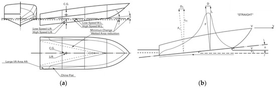
Figure 1.
Example of diagrams traditionally used during the engineering design process for evaluating: (a) hull behavior as speed varies; (b) trend of the forces on the hull while under way.
Besides, numerical modeling and simulations can describe, in mathematical terms, the multiple aspects of the real world and their evolution over time, which could be an essential part of the ship design process and optimization [21]. Today, the role of modeling is widely consolidated in many sectors, thanks to the intense increase in computer speed that now allows the scientific calculation of complex systems, otherwise inaccessible to comprehension, completing more traditional tools.
Unfortunately, it is far from having mathematical models and calculation tools so handy and versatile to provide valid answers in all the various fields of ship design, often confined to specific aspects (as in [22]). This concern is particularly observed in the realization of a high-performance crafts: their optimization is a question of solving the fluid dynamics equations around the boat, taking into account the variability of winds, waves, and speed [23].
However, the interaction between the fluids (air and water) and the structural components (hull, submerged appendages, sails, and mast) must also be considered to indicate what are the most important aspects to consider with the goal of minimizing water resistance and maximizing the thrust of the sails. Furthermore, it is still necessary to manage a complex modelling, taking into account aspects such as the viscosity of the water, the transition between laminar and turbulent flows (with the vortices born), the turbulent trails generated by the interaction of the flow with the immersed parts, the shape of the wave that is generated on the hull and more [24]. For example, equations that shape the coupling between the air and water motions and the resulting waveform should be solved, supplemented by additional mathematical expressions constituting the models for the calculation of turbulent energy and its rate of dissipation [25]. It follows that the ability to make accurate calculations is not always within the reach of all designers and even partial solutions take their usefulness.
On the other side, a large number of experiments studies the behavior of the hulls in navigational conditions. In [26], the hydrodynamic effect of impacts caused by slamming on racing yachts is experimentally investigated. Special measurement solutions have been designed and developed to measure pressures and local consequence on structures. A methodology to scale up these results in diverse cases is only mentioned.
Beyond a specific method, technique, or device being used during experiments, expedients have to be adopted for filtering and interpreting the large amount of data. In [27], a statistical approach is proposed in the way to transform a time-depending measure (of accelerations) in an overall respond on the structure.
2. Materials and Methods
The present work intends to show how experimental mechanics techniques and numerical methods can be conveniently use in supporting design choices without an excessive intensification in the workload or in the complexity of the design procedure. In particular, here are presented:
- In-lab experiments with the aim at investigating the behavior of fiberglass used in the boat manufacturing, by testing specimens in tensile, flexural and impact tests. Different mixtures of resins and glass reinforcements are also compared with the scope to select the best combinations of material properties.
- In-field experiments, installing a network of sensors and instruments on the RIB for acquiring data during sailing: three outings on the sea in normal and extreme conditions, with the aim to evaluate the stresses and strains in a hull gliding through waves.
- Smoothed-particle hydrodynamics (SPH) numerical simulations combined with FEM with the scope to investigate the effect of waves motion and impact on ship structures.
2.1. In-Lab Experiments
The current regulation in yachts design is UNI EN ISO 12215 regarding hull construction and scantlings for small crafts especially in that part (Part 5) concerning the design pressures for monohulls, design stresses, scantlings determination. It specifically suggests the use of tensile, flexural, and interlaminar shear tests as material test methods providing the minimum mechanical properties that composite materials must have to be used to build the hull (Table 1).

Table 1.
Mechanical properties, reference standards for testing and minimum thresholds (ISO 12215).
Then, a specific standard was used in each, able to provide information to carry out that test. These standards detail aspects as the geometry of test equipment, the testing speed, the dimensions and number of specimens. In particular, it states that, for each type of resin under investigation, a minimum of five specimens is required.
In this study, seven resins were analyzed and compared: epoxy, orthophtalic, iso-neopentilic, vinylester, and three different polyesters. Tests were carried out using an Italsigma hydraulic testing machine with 100 kN HBM Gmbh load cells.
2.1.1. Tensile Tests
The tensile tests were planned and carried out following the indications of ISO 527-1/4 standards. Since the sheet was made of layers of coupled mat, the direction of tension made no significant difference. The samples had nominal dimensions of width 25 mm, length 250 or 150 mm, and thickness 4 mm. Supports in aluminum 50 mm long and 3 mm thick were glued to the samples using LOCTITE 9466 AB glue. A minimum of five samples were tested for each resin system. The test speed was 0.02 mm/s (Figure 2a).
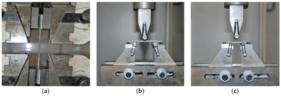
Figure 2.
Equipment and samples during the (a) tensile, (b) flexural, and (c) interlaminar shear tests.
2.1.2. Flexural Tests
The flexural tests were planned and carried out to the ISO 178 standard. The samples were realized in rectangular shape, 10 mm length, 80 mm width, 3.5 mm thickness, and distance between supports of 56 mm, or four manually laminated samples 15 mm length, 110 mm width, 5.5 mm thickness, and distance 90 mm. For each resin system, at least five samples were tested. The test speed was 0.02 mm/s (Figure 2b).
2.1.3. Interlaminar Shear Tests
The interlaminar shear tests were planned and carried out to the indications of the ISO 14130 standard. The samples were rectangular, length 10 mm, height 40 mm, width 5 mm, height 20 mm, with the distance between supports of 17.5 mm. The test speed was 0.02 mm/s (Figure 2c).
The failure methods were investigated with particular attention.
2.2. In-Field Experiments
A prototype RIB, based on the Mariner 530 model, was built and used for stress tests. It was asix-seater, 450 kg boat, 4.95 m long, and 1.75 m in the beam, with a 15 kW/20 hp engine and a 400 kg of load (Figure 3). Built in a specific GRP, using a VARTM technology (Figure 4), both material properties and process parameters were investigated and selected in the way to represent a good product compromise in terms of marketability. No changes in design were implemented at this stage respect to other similar models, designed in accordance with the designers’ traditions, mainly with respect to the technical prescriptions from standards ISO 12215-1/8.
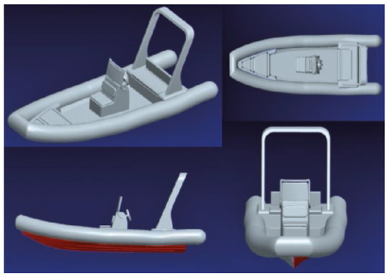
Figure 3.
A prototype RIB used for sailing tests.
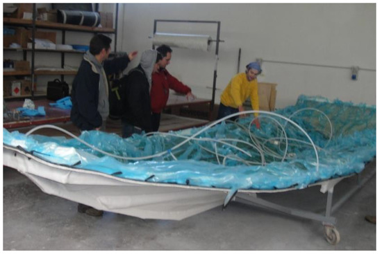
Figure 4.
Use of a VARTM process in hull building.
Experiments monitored accelerations and strains installing strain gages and accelerometers on the boat (Figure 5). Accelerations were measured in the fore and aft and athwartships directions of the hull. The values of acceleration made it possible to correlate tests carried out in different sea conditions, but also to provide an interesting overall parameter for evaluating the comfort.
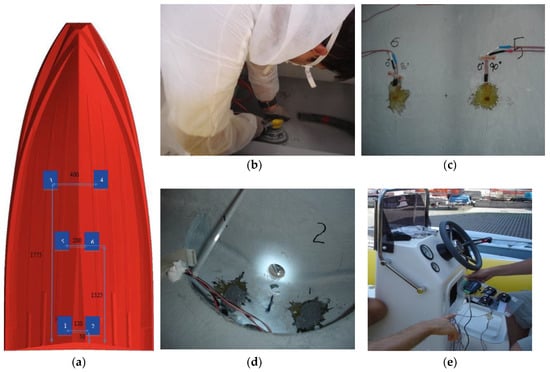
Figure 5.
Placement of the strain gauges: (a) map of placement; (b) preparing the surfaces for gluing on the strain gauges; (c) train gauges in the cockpit, affected by the weight of the fuel tank and driver; (d) stern strain gauges to monitor the most stressed areas; (e) data acquisition and other ICT devices.
Strains were measured in six different locations on the hull, revealing longitudinal and transversal deformations. In total, 15 measures were realized: 3 accelerations and 12 deformations. In particular, the strain gauges were positioned in the way to monitor the most remarkable parts in terms of water effect during the different conditions and speeds of sailing (Figure 5a). The duplication of strain gages (and measures) in a symmetrical configuration was preferred for a better investigation of unexpected phenomena.
Boat surfaces were carefully cleaned and treated before gluing the strain gauges (Figure 5b). The glue was also used to protect these sensors (Figure 5c). The weight effects of the fuel tank and driver were also monitored (Figure 5d). A three-axis accelerometer was placed in the cockpit, together with data acquisition, signal conditioners/wireless amplifiers and other electronic devices (Figure 5e). The tests were carried out on three different days, two with calm sea, to verify the sensitivity of the measurement system even under very low stresses. In each test day, several measurement sessions using trajectories, speeds, and acceleration were conducted in an attempt to faithfully represent various driving styles. Inside each test day, several test sessions were realized. Each session of measure lasted about 1 min: this choice made it easier to analyze data and separate the effects.
2.3. Numerical Simulations
The numerical study of the impact between a moving body and a free surface of water is a familiar problem both in the naval and aeronautical fields, and concerns the interaction phenomena between hulls, offshore structures, and aircraft with the water surface, sometimes even considering in its wave motion. The main purpose of this type of research is to trace the load transferred during the impact to the structure under examination to verify the conditions of resistance or proceed to a redesign. Usually, these studies start from experimental tests, interpreted through empirical laws and, only recently, studied through numerical simulations.
These investigations must be implemented by numerical codes that permit to properly model the fluid–structure interaction. These codes originate from Lagrangian formulation programs developed for crash problems, but also allow the interface of continuous based on Eulerian spatial description. In this kind of calculations, the fluid constitutive model, the fluid–structure interaction algorithms and the computational efficacy represent critical aspects. This study presents an alternative approach based on mixing finite elements (FE) and smoothed-particle hydrodynamics (SPH) to permit a better evaluation of the effects of interaction between fluid and structure.
Slamming simulations were performed with LS-DYNA commercial software. SPH elements were used for fluid modeling. SPH particles, equispaced and of identical size (radius of influence of 25 mm) were placed in a fluid region of dimensions 7 × 3 m for a depth of 1.5 m. The properties of the fluid were modelled by means of a state equation according to the Gruneisen formulation (Equation (1)).
where E represents the internal energy per unit of volume, and μ = η – 1 where η is the ratio between final and initial density. The numerical values of the other constants are reported in Table 2.
Table 2.
Water constants according to the Gruneisen model.
The fluid is initially at rest, is subject only to gravity acceleration and is constrained in space by non-reflecting edges, so as to avoid the reflection of the pressure waves.
The hull was modelled using shell finite elements (FE) and four nodes with two points of integration in the thickness for a total of 26,000 elements (as shown in Figure 6). The hull thickness was considered constant throughout the model, and equal to 12 mm. The material had the characteristics of a composite laminate with a matt of glass fiber and polyester matrix, with properties of E1 = E2 = 24 GPa, ν = 0.3, ρ = 2800 Kg/m3, implemented as an elastic linear material without damage models.
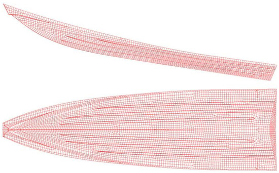
Figure 6.
Discretization of the model through shell elements. The hull is discretized by 26,000 shell elements with four nodes with two points of integration in the thickness.
The numerical simulation reproduced the entry into the water (similar to a drop test) with an entry speed of 8 m/s. The speed component was purely vertical and the hulls inclined with the bow to a greater portion of the stern (as shown in Figure 6).
3. Results
3.1. Material Properties
3.1.1. Tensile Properties
Tensile tests provided a measure of the strength (σ) and stiffness (E) of the laminate as a whole, thus including both the contribution of these seven resins and fibers in their specific stratification. In particular, Figure 7a shows the stress-strain diagrams noting that:
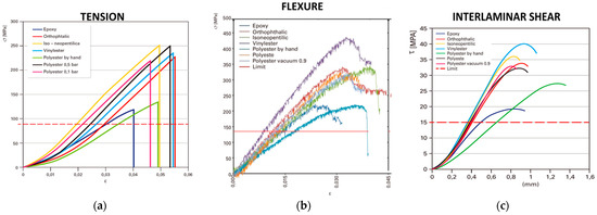
Figure 7.
Diagram and standard limits for: (a) tensile tests; (b) flexural tests; (c) interlaminar shear tests.
- -
- The standard requires tensile strength of 80 MPa which is amply satisfied by all the resin systems. As a practical result, all the materials and sequence of stratification under investigation are adequate for creating the strength laid down by the standard.
- -
- Almost all the resins showed an ultimate tensile stress of between 220 and 250 MPa with better characteristics for isoneopentilic and orthophthalic resins at 0.5 bar, while hand laminated polyester resin and epoxy resin had the worst performance.
- -
- For hand laminated polyester, this performance is due to the greater percentage of resin compared with fiber and to the presence of air porosity in the manual laminate compared with other techniques (VARTM).
- -
- Epoxy resin shows decidedly low values in relation to the problems illustrated in starting reticulation of the resin in the sample sheet.
3.1.2. Flexural Properties
Similarly, Figure 7b shows the stress–strain diagrams for the flexural tests noting that:
- -
- The standard demands flexural strength of 135 MPa and a flexural modulus of 5200 MPa which is amply satisfied by all the resin systems; so they are all adequate for offering the strength specified by the standard.
The resins can be grouped into three categories:
- -
- Best resin: Vinylester, which has properties decidedly superior to the others but is more expensive; it is recommended for special or high-performance applications.
- -
- Hand laminated polyester and epoxy: these have the worst characteristics, but it must be underlined that the poor result of epoxy resin is linked to the fact that it was made at environmental temperature, normally epoxy resins have much better performance.
- -
- Others: they all show very similar behavior and are equivalent.
3.1.3. Interlaminar Shear Properties
Finally, Figure 7c shows the main results obtained from the interlaminar shear tests. For each sample, the shear methods were classified, and the calculation of the maximum shear force is shown. In particular, it is shown the shear-displacement diagrams where it is possible to note that:
- -
- the standard requires interlaminar shear resistance of 15 MPa which was largely satisfied by all the resin systems;
- -
- the best system is once again vinylester with performance decidedly better than that of the others. In this case, epoxy resin shows unusually low values for the partial reticulation of the sample sheet;
- -
- the remaining resins have similar behavior with a slight preference for isonepentilic resin.
3.2. Loads and Deformations
Each navigation tests started with the transport through the port and launch in the basin (Figure 8). Figure 9 shows an example of a cruising followed during a measurement session, starting from calm water in the port followed by sudden accelerations. In particular, the GPS trace shows the presence of specific criteria in the measurements. In this case, for instance, the criterion was to reach the maximum speed (about 20 km/h), then turn in a fixed time through a set angle marked on the helm. In this way, the RIB ran over its own wake, with waves of roughly the same height, to improve the repeatability of the measurements.
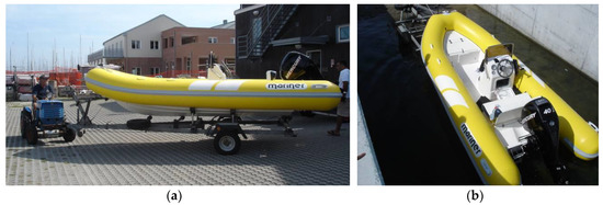
Figure 8.
Initial phase: (a) transport through the port and (b) launch in the basin of the rigid inflatable instrumented boat.
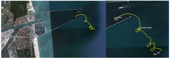
Figure 9.
Example of route followed during one of the test sessions: strong acceleration and repeated rotations made it possible to investigate the effect of self-generated waves on the hull.
Figure 10 shows an example of a little parts of measures acquired during the test. In particular, it shortly displays, in three different moments (lasting, respectively, 8, 3.5, and 3 s.) of the experiment, the accelerations, measured by the accelerometer along the vertical direction, and the relative strains, measured by three strain gauges. As said, the overall experiment involved 15 time-dependent measures: 3 accelerations (one component per each direction) and 12 deformations (two planar components per each one of the 6 locations). Measures were recorded for almost one-hour per each one of the two different days of testing. This large amount of data has to be fully analyzed yet, also using statistical methods (as in [28]), but preliminary considerations can be provided.
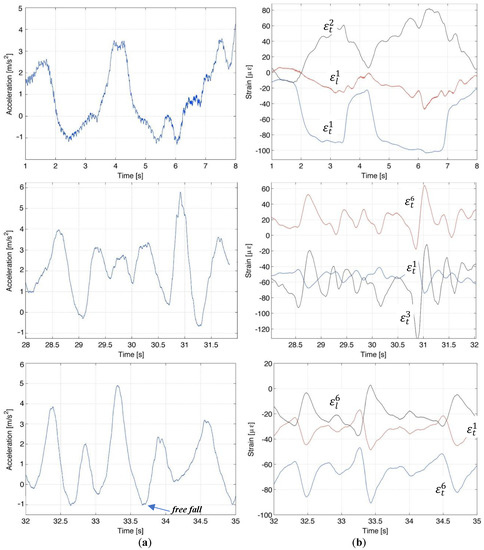
Figure 10.
Investigating the hull behavior in different moments: (a) accelerations and (b) strains.
As first, the measures confirm that maximum strains during tests (and related stresses), were very far from the safety limits of fiberglass as measured in lab (<0.1% against >4%), confirming the material selections and the other design assumptions. Additionally, data show that in the accelerations only the vertical component is really relevant. On the contrary, in the case of deformation/stresses, no direction can be neglected.
With the aim at entering in details of measures, it has to be firstly highlighted that Figure 10a shows the initial phase of acceleration, used to move the boat from quite (T = 0) to a cruise speed (15/16 knots) before a second stage of acceleration (not represented) toward the maximum speed (20 knots). During this initial part, a sailing direction was maintained as much as possible perpendicular to the waves in a sea state of 3 in the WMO code. Experimental measures were not filtered.
Diagrams in Figure 10b report the longitudinal and transversal strains measured during the same periods by the ith strain gauge and labelled as, respectively, and .
It is possible to notice several aspects as:
- -
- There is a substantial correspondence in term of time-dependent trends between accelerations and strains. Slight differences are mainly related to the facts that: (a) the strain measure is influenced by all three components of the acceleration (while only one is displayed); (b) there is a little, but not null distance between the positions where accelerometer and strain-gauges are located. Same considerations have to be taken in count when comparing the time-depending trends measured by strain-gauges.
- -
- Acceleration has a maximum value of 6 m/s2 corresponding to peaks of strain of 120–140 μm.
- -
- Strain gauges symmetrically positioned (e.g., strain gauges 1 and 2) report anti-symmetric trends in strains (as in the case of and ). This anti-symmetry in the system is not complete since the external loads are not perfectly balanced with respect to the boat symmetry.
- -
- Longitudinal strains are significantly lower than transversal strains (e.g., and ). In addition, as in the case of , located at the rear of the boat, compression state during the acceleration is correctly detected.
- -
- Transversal strains improve from the stern to the blow (e.g., and ) but the maximum is located around the middle of the hull (e.g., ).
- -
- As the speed increases, the blows on the waves become more frequent, with accelerating peaks approaching, but also with less pronounced tendencies.
- -
- From time to time, there are some free fall phases, when the acceleration in descent is equivalent to the gravitational acceleration.
3.3. Numerical Predictions
This simulation permitted to investigate the situation of the hull impacting against the water surface in specific conditions (e.g., impact speed, impact direction, and so on) in terms of time evolution of displacement, speed, and acceleration (Figure 11).
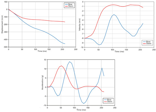
Figure 11.
Displacement, speed and acceleration of the bow and stern during the impact.
It is possible to note that the maximum acceleration is achieved shortly after the start of the impact, when the speed is high and only a small part of the hull is in contact with the water. This force counteracts the inertia of the craft. A moment is then generated which deforms the hull to the outside and tends to ‘push’ the structure. As water enters the inlet, the wet surface of the hull increases and elastic strain energy accumulates. As the wetted surface increases, the moment caused by the hydrodynamic force increases and generates a bending moment that is opposite and stronger than that generated by inertia, bringing the deformation of the hull back to neutral position.
Figure 12 shows a sequence of images of the water entering while Figure 13 shows the (Von Mises) stress level associated with the deformations of the hull. The colors in the figure represent the range from 0 MPa (blue) to 50 MPa (red). The most stressed regions are the keel, where the hydrodynamic pressure is maximum, and the terminal part of the side members, where a greater mass is concentrated and therefore the elastic deformation is maximum.
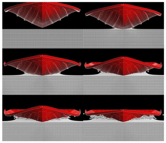
Figure 12.
Sequence of the simulation of the entry into the water of the hull.
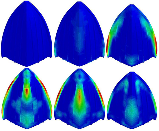
Figure 13.
Longitudinal tensions in the hull generated during slamming.
4. Discussion and Conclusions
This article aims at demonstrating how numerical models and experimental techniques, even in the case of simplified and quick procedures, can be conveniently used for supporting the designers in their decisive tasks.
Concerning those experiments that can be performed in lab, the article shows how they can be implemented in accordance with well-known standards arriving to a practical characterization of the resin systems to support a final selection. Experiments also provided additional evidence that can be useful for a more informed choice, for instance:
- -
- The epoxy system does not appear to be usable at typical temperatures for boat production.
- -
- There are significant differences in mechanical performances obtainable with advanced techniques compared with the classic manual methods.
Concerning the experiments in sailing conditions, this experimental procedure aimed to provide a simple method that makes possible to create an ‘instrumented prototype’ for quick resistance tests and design evaluations. This result has almost been achieved. For instance, from data, it is possible to extract the response of the craft in terms of strains (measured in specific points) respect to the trend in the vertical acceleration. Thus, the prototype can be used to investigate the behavior of the craft during normal operation, but also in extreme conditions laid down by the specifications or future regulations such as, for example, the boat being dropped from heights from 3 to 6 m, or sailing on moderate or rough water.
In particular, the article shows the advantages of the RIBs in respect to other traditional boats, but also its limits when its specificities are not reflected in the design process. Extremely safe, thanks to the inflatable collar that makes it unsinkable and increases the lateral stability, but also thanks to its low weight and dimension, this craft presents several functional benefits. Driven by very powerful engines in relation to their displacement, RIBs can plane on waves and do not simply slide along the water. This, which means much of the hull spends a great deal of its time in the air, considerably reducing drag and optimizing speed and efficiency.
At once, from experimental data it was possible to immediately observe the intense impulsive loads acting on its structures, together with a maximum at the intersection between the hull and the water line. This peak moves and changes in intensity as the hull planes, decreasing and moving astern the more of the hull is out of the water. At the same time, the hull undergoes strong and continual impacts on the water surface that demand careful and robust design. Besides, clearly understanding what happens in the interaction between fluid and structure is not an easy task, especially in non-nominal conditions as in the case of a strangely shaped hull moving in rapid zigzags among the waves.
With the aim of moving a step toward this comprehension, numerical models and simulations can provide relevant input, as demonstrated hereby. Through the coupled SPH and FEM methods, it was possible to study the complex aspect of fluid–structural interaction and the mutual influence between the fluid motion and the hull deformation. For instance, observing the behavior of stern and bow during their entry into the water, it was possible to recognize that the stern, the first to touch the water, is also the first to decelerate. This generates a moment on the hull that slightly increases the fall speed of the bow, which impacts on the water afterwards. The peaks of the maximum accelerations of the stern and the bow are therefore out of phase.
Funding
This research: named ‘New concept boats’, was funded by the Emilia Romagna Region, Italy, as part of the Regional Operation Program that uses resources from European Regional Development Fund (ERDF) with the aim to strengthen economic and social cohesion in the European Union.
Acknowledgments
The research was supported by Mariner Srl, Stilplast Srl, Ravenna with technical support and donations in kind. In-lab experiments were carried out at the MaSTeR Lab, University of Bologna, under the supervision of Lorenzo Donati and Enrico Troiani. In field experiments were carried out in front of the port of Ravenna, Italy, Adriatic Sea, under the supervision of Giangiacomo Minak. Special thanks to Vanda Roversi, Riccardo Panciroli, and Ana Pavlovic for their efforts.
Conflicts of Interest
The author declares no conflict of interest.
References
- Pike, D. The Complete RIB Manual: The Definitive Guide to Design, Handling and Maintenance; A&C Black: London, UK, 2013. [Google Scholar]
- Salvesen, N.; Tuck, E.O.; Faltinsen, O. Ship motions and sea loads. SNAME Trans. 1970, 78, 250–287. [Google Scholar]
- Townsend, N.C.; Wilson, P.A.; Austen, S. What influences rigid inflatable boat motions? Proc. Inst. Mech. Eng. Part M 2008, 222, 207–217. [Google Scholar] [CrossRef]
- Versmissen, H.; Haasnoot, T. Rigid Inflatable Boats. In Handbook on Drowning. Task Force on Rescue–Rescue Techniques; Brewster, C.B., Brons, R.K., Eds.; Springer: Berlin, Germany, 2007; Volume 5, p. 264. [Google Scholar]
- Pollard, S.F. Boatbuilding with Aluminum: A Complete Guide for the Amateur and Small Shop, 2nd ed.; McGraw-Hill Professional: New York, NY, USA, 2006. [Google Scholar]
- Fragassa, C. From Design to Production: An integrated advanced methodology to speed up the industrialization of wooden boats. J. Ship Prod. Des. 2017, 33, 1–10. [Google Scholar] [CrossRef]
- Marsh, G. 50 years of reinforced plastic boats. Reinf. Plast. 2006, 50, 16–19. [Google Scholar] [CrossRef]
- Marsh, G. Composites boost patrol craft performance. Reinf. Plast. 2006, 50, 18–22. [Google Scholar] [CrossRef]
- De Paola, S.; Minak, G.; Fragassa, C.; Pavlovic, A. Green Composites: A Review of State of Art. In Proceedings of the 30th Danubia Adria Symposium on Advanced Mechanics, Primosten, Croatia, 25–28 September 2013; Croatian Society of Mechanics: Zagreb, Croatia, 2013; pp. 77–78. [Google Scholar]
- Hyseni, A.; De Paola, S.; Minak, G.; Fragassa, C. Mechanical Characterization of EcoComposites. In Proceedings of the 30th Danubia Adria Symposium on Advanced Mechanics, Primosten, Croatia, 25–28 September 2013; Croatian Society of Mechanics: Zagreb, Croatia, 2013; pp. 175–176. [Google Scholar]
- Fragassa, C.; Pavlovic, A.; Santulli, C. Mechanical and impact characterisation of flax and basalt fibre bio-vinylester composites and their hybrids. Compos. Part B Eng. 2018, 137, 247–259. [Google Scholar] [CrossRef]
- Zivkovic, I.; Fragassa, C.; Pavlovic, A.; Brugo, T. Influence of moisture absorption on the impact properties of flax, basalt and hybrid flax/basalt fiber reinforced green composites. Compos. Part B Eng. 2017, 111, 148–164. [Google Scholar] [CrossRef]
- Halswell, P.K.; Wilson, P.A.; Taunton, D.J.; Austen, S. Hydroelastic inflatable boats: Relevant literature and new design considerations. Trans. R. Inst. Nav. Archit. Part B 2012, 154, B39–B49. [Google Scholar]
- Townsend, N.C.; Coe, T.E.; Wilson, P.A.; Shenoi, R.A. High speed marine craft motion mitigation using flexible hull design. Ocean Eng. 2012, 42, 126–134. [Google Scholar] [CrossRef]
- Hudson, D.A.; Turnock, S.R.; Lewis, S.G. Predicting motions of high-speed rigid inflatable boats: Improved wedge impact prediction. In Proceedings of the Ninth International Conference on Fast Sea Transportation (FAST2007), Shanghai, China, 23–27 September 2007; pp. 377–383. [Google Scholar]
- Wines, C. Stability and Safety Issues for High Speed Operation of Rigid Inflatable Boats. In Proceedings of the 11th International Conference on Fast Sea Transportation, Honolulu, HI, USA, 26–29 September 2011; pp. 844–849. [Google Scholar]
- Payne, P.R. The vertical impact of a wedge on a fluid. Ocean Eng. 1981, 8, 421–436. [Google Scholar] [CrossRef]
- Von Kármán, T.H. The Impact of Seaplane Floats during Landing; TN No. 321; National Advisory Committee on Aeronautics (NACA): Washington, DC, USA, 1929.
- Schumann, B.; Ferraro, M.; Surendra, A.; Scanlan, J.P.; Fangohr, H. Better design decisions through operational modeling during the early design phases. J. Aerosp. Inf. Syst. 2014, 11, 195–210. [Google Scholar] [CrossRef]
- Jones, A.T. Design Space Exploration and Optimization Using Modern Ship Design Tools. Ph.D. Thesis, Massachusetts Institute of Technology, Cambridge, MA, USA, 2014. [Google Scholar]
- Savitsky, D. Hydrodynamic design of planing hulls. Mar. Technol. 1964, 1, 71–96. [Google Scholar]
- Abrate, S. Hull slam. Appl. Mech. Rev. 2011, 64, 060803. [Google Scholar] [CrossRef]
- Ircani, A.; Martelli, M.; Viviani, M.; Altosole, M.; Podenzana-Bonvino, C.; Grassi, D. A simulation approach for planing boats propulsion and manoeuvrability. Trans. R. Inst. Nav. Archit. Part B 2016, 158, 27–42. [Google Scholar]
- Panciroli, R. Hydroelastic impacts of deformable wedges. In Dynamic Failure of Composite and Sandwich Structures; Abrate, S., Castanié, B., Rajapakse, Y., Eds.; Springer: New York, NY, USA, 2013; pp. 1–45. [Google Scholar]
- Almeter, J.M. Resistance prediction of planing hulls: State of the art. A comparison of empirical vs. computational planing models. Mar. Technol. 1993, 30, 297–307. [Google Scholar]
- Lee, F.J.; Wilson, P.A. Experimental study of the slamming in a modern racing yacht. J. Sailboat Technol. 2010, 1, 1–28. [Google Scholar]
- Hobbs, M.; Manganelli, P. Measurement of accelerations and keel loads on canting keel race yachts. In Proceedings of the RINA International Conference—Modern Yacht, Southampton, UK, 11–12 October 2007; pp. 115–121. [Google Scholar]
- Riley, M.R. A Deterministic Approach for Characterizing Wave Impact Response Motions of a High-Speed Planing Hull; NSWCCD-23-TM-2012/05; Naval Surface Warfare Center Carderock: West Bethesda, MD, USA, 2012.
© 2019 by the author. Licensee MDPI, Basel, Switzerland. This article is an open access article distributed under the terms and conditions of the Creative Commons Attribution (CC BY) license (http://creativecommons.org/licenses/by/4.0/).