A Smart Energy Harvesting Platform for Wireless Sensor Network Applications

1
Department of Computer Engineering and Informatics, University of Patras, 26442 Patras, Greece
2
Computer Technology Institute and Press “Diophantus”, 26504 Patras, Greece
*
Author to whom correspondence should be addressed.
†
This paper is an extended version of our paper published in IoTI4 2019: International Workshop on IoT Applications and Industry 4.0, Santorini Island, Greece, 29–31 May 2019.
Information 2019, 10(11), 345; https://doi.org/10.3390/info10110345
Submission received: 30 September 2019
/
Revised: 25 October 2019
/
Accepted: 1 November 2019
/
Published: 6 November 2019
(This article belongs to the Special Issue IoT Applications and Industry 4.0)
Abstract
:Advances in micro-electro-mechanical systems (MEMS) as well as the solutions for power scavenging can now provide feasible alternatives in a variety of applications. Wireless sensor networks (WSN), which operate on rechargeable batteries, could be based on a fresh basis which aims both at environmental power collection and wireless charging in various shapes and scales. Consequently, a potential illimitable energy supply can override the hypothesis of the limited energy budget (which can also impact the system’s efficiency). The presented platform is able to efficiently power a low power IoT system with processing, sensing and wireless transmission potentials. It incorporates a cutting-edge energy management IC that enables exceptional energy harvesting, applicable on low power and downsized energy generators. In contrast to other schemes, it supports not only a range of power supply alternatives, but also a compound energy depository system. The objective of this paper is to describe the design of the system, the integrated intelligence and the power autonomy performance.
1. Introduction
Wireless sensor networks render their existence in modernized lives day after day more powerful and essential. They are one of the cornerstones of concepts such as industry 4.0, smart cities and the Internet of Things, so they can obtain all the required data and develop smart systems for security, life quality enhancement, pre-maintenance measures and many other utilities. One of the many challenges we are called to confront in this new situation is how these systems can become self sufficient in terms of energy and also function at an adequate level.
Energy collection can commonly be analyzed in two main classes: (a) Depending only on harvested energy available at the moment and (b) utilizing a storage module to save excessive ambient energy for future use. In the first case, as the system is energized straight from the harvester it can only stay in service while the harvester generates enough power. The second case eliminates a major drawback of the first, where the system alternates between active and inactive states. It incorporates a storage module like a battery or a capacitor to save excessive harvested energy so the system can stay operational even when ambient conditions are such that the harvester cannot generate enough energy. Many implementations utilize a two factor storage architecture where capacitors are used along with rechargeable batteries. Power is mainly drawn from the capacitors as they offer much more charge and discharge cycles than the batteries, while the batteries are used as auxiliary.
In particular, in this article we design an energy harvesting, storage and supply solution for a WSN that is used for both environmental monitoring and event detection regarding vehicles and traffic. However, the transportation application does not limit the use of this hardware platform for a large range of low power IoT use cases. In such systems, the sensing and communication motes are low-cost, battery-operated devices with the responsibility to perform specific tasks, and transfer the collected data to a local gateway for processing, storage and further upload them to a cloud server. Hence, our system aims to implement smart energy management by applying a hierarchical schema to define the potential power source, so that the mote can perform its tasks uninterrupted.
This work is the extendsion version of [1]. Our contributions: Here we demonstrate our results in our effort to make an energy management platform with the ability to make sensor motes autonomous in terms of energy. We are developing a power supply platform that can merge the following developments in an all-in-one system which can power low-power devices. Thus, we:
- introduce a hybrid two factor energy storage architecture by combining rechargeable and non-rechargeable batteries
- integrate features such as temperature, overcharge and deep discharge protection
- support a great variety of energy harvesting technologies (solar, piezoelectric, vibrations, RF harvesting, electromagnetic)
- implement a hierarchical energy management scheme to make more efficient use of available energy and prolong a system’s lifetime.
- enhance battery charging rate
- prototype a custom-built energy harvesting and management hardware module that enables the above characteristics
Related work: In the latest state of the art, we can discover publications that are perfectly matched with the present one, relating hardware design and energy harvesting. Notably, [2] discusses a novel type of piezoelectric energy harvesting device that can possibly be used in wearable appliances with the intent to deliver high power output at low frequency. An architecture process with a dual band flexible rectenna and a solar cell is presented in [3]. Wireless power transfer is among the disruptive technologies so a heightened research activity is observed in this area. In [4] a hybrid source switch-based RF Wireless energy method with the ability to adaptively switch through high power RF sources is proposed, while in [5] a solution to the complication of battery constraints on the user’s appliance is proposed that utilizes wireless power transfer based on resonant coupling. In [6], a micropower, batteryless, energy autonomous RF tag is described, alongside the corresponding architecture, to address localization applications to track goods, people, logistics, etc. To complete our references to wireless power transfer, we would like to provide some algorithmic approaches to this subject like [7,8] where the presented algorithms aim to further increase in a wireless power network the maximum power fueled. As electromagnetic radiation coexists with RF harvesting, we see an increase in studies on this subject in recent years. Some propose ways to locate low radiation paths to navigate radiation sensitive devices when numerous radiation sources are active ([9]), while others ([10]) propose scheduling techniques to control radiation.
Similar to this work, in [11], a hybrid storage system using both rechargeable batteries and supercapacitors with solar energy harvesters architecture is introduced, while in [12] an efficient platform with multiple energy sources as input is proposed and is validated in a WSN surveillance implementation. In [13] a multi-transducer platform for piezoelectric and solar harvesting technologies for both indoor and outdoor use is deployed. The authors in [14] present an energy harvesting wireless sensor node, called Sparrow, which can offer an autonomous, energy harvesting WSN. In [15], an integrated converter that supports multiple and heterogeneous sources for energy harvesting tasks has been designed which can potentially achieve efficiency up to for the single harvester case. Regarding the mechanical harvesters, the authors in [16] present a nonlinear bistable piezoelectric converter that harvests energy from environmental vibrations. During the testing validation the piezoelectric converter achieved in the rms voltage. In addition, [17] presents a wideband electromagnetic vibration-to-electrical micro power generator which is made by parylene cantilevers and allows larger amounts of power to be produced. Finally, [18] presents an efficient technique for finding the setup which offers the maximum power of an energy harvester, by controlling the operating voltage of the harvesting device.
2. Energy Management Prototype
2.1. Energy Management
In order to address several challenges (implement intelligence on the most profitable use of energy from accessible sources, support different types of energy harvesters, etc.) and come to a novel result assimilating rising approaches and technologies, we are conducting a research on the layout of an energy management board with the ability to support various energy harvesting units and storage modules. The model we are adopting is based on a concept of a mote that integrates sensing, processing and communication modules. An energy supply unit is therefore needed to provide power to the mote so each module can operate efficiently (Figure 1).
Energy Management Design
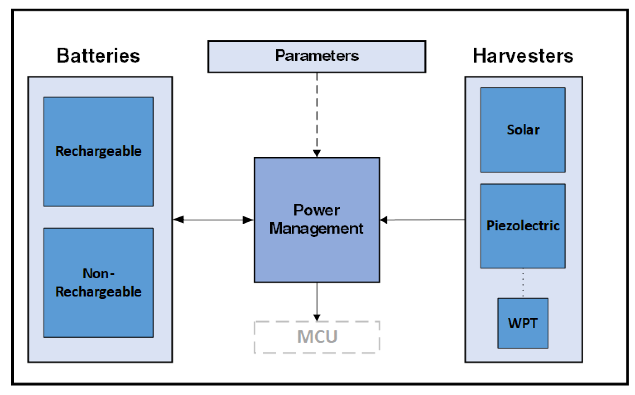
The power supply system we introduce, with power management capabilities, combines three essential units as depicted in Figure 2:
- The energy reservoir that retains the energy collected for prospective use.
- The energy harvesters that collect ambient energy.
- Finally, the power management unit accountable for both the charging and discharging procedure of batteries and also provide stable DC power supply. It also incorporates a prioritization system that allows the effective use of feasible power.
2.2. Energy Harvesting Sources
As mentioned above, a large collection of low-power energy harvesters in the range of and mW is currently available. Our system can support harvesters like thermoelectric, piezolectric, solar, vibration, RF and electromagnetic. The harvesters shown bellow are selected based on a prospective road infrastructure deployment.
2.2.1. RF Energy
We have included on our board, the P2110B RF harvester from Powercast ([19]) to facilitate Wireless Power Transfer. This type of harvester renders the energy supply independent of ambient conditions. There are various approaches like:
- Collection of ambient RF radiation, originating from radio wave emitting devices like routers and cell towers.
- Collection of RF radiation from RF chargers, which are devices that transmit electromagnetic waves in a specific area.
In this work we implement the second case, where by using the corresponding rectenna and receiver we achieve wireless power charging.
2.2.2. Solar Energy
Solar harvesters are one of the most used types of energy harvesters due to several attributes listed below:
- a
- Their power conversion efficiency can come close to
- b
- Easy integration and fast deployment
- c
- They can generate power for varying light intensity making them suitable for use both inside and outside
- d
- They can sufficiently charge rechargeable batteries while also powering the connected device
2.2.3. Piezoelectric Energy
Piezolectric harvesters are quite attractive as they have the ability to transform mechanical tension to electrical energy. Mechanical tension may originate from numerous sources, like:
- a
- Pressure
- b
- Vibrations
- c
- Human or animal movement
They can generate power of a few mW making them sufficient to provide power to low-power systems.
2.3. Implementation
Here, a multiplex concurrent input energy harvesting and power supply system is presented. The three core components it facilitates are LTC3331 (https://www.analog.com/en/products/ltc3331.html), LTC3335 (https://www.analog.com/en/products/ltc3335.html) and LTC4071 (https://www.analog.com/en/products/ltc4071.html), from Analog Devices ([20]).
The LTC3331 is a configurable IC that has the ability to efficiently charge a rechargeable battery or capacitor and also provide power to an output named while using ambient energy. The output voltage is configurable with 8 distinct hardware controlled modes through pins , taking values from 1.8 V to 5 V. It can facilitate both AC and DC output energy harvesters (on pins and ) without the use of external hardware as it has an integrated bridge rectifier, while also providing 16 different configurations through pins for the harvester input in order to optimize performance and operate close to peak power point without external power adapters. The integrated battery charger can be configured to accommodate different types of single cell batteries (through pins FLOAT[1:0] and LBSEL) and offers configurations about maximum, minimum voltage and also the threshold that the battery voltage has to reach before a load is applied to it again, after the battery has reached the minimum voltage and is disconnected from the rest of the system. In Figure 3, it is illustrated a typical example of the connections and peripheral hardware LTC3331 require to operate.
The integrated battery charger can only provide the batteries with a fraction of the energy received from the harvesters, even when the harvester is at the peak power output and a very small load is connected on the LTC3331 output. Due to this, the batteries are charging at a slow rate and significant amount of ambient energy, that could potentially provide more power to the batteries, remains unused. To solve this problem we paired it with the LTC4071 shunt battery charger. The connection of the charger with the rest of the system is shown in Figure 4. The integrated charger, charges the batteries only when it has enough energy to provide power to the output and also to the batteries. Otherwise, it just powers the output. In order to keep this feature and provide a steady power supply, we use the output of the integrated battery charger () to activate a mosfet that acts as a switch, the input of the external charger () with harvester input rail () of the LTC3331. The output of the external charger () is connected to the battery charging input (), which is shorted to pin. is the input for the buck/boost converter and needs to be shorted to which acts as battery charging input while harvested energy is available and as battery output while harvested energy is insufficient in order to use the energy stored in the battery. With this configuration the charger can supply up to 50 mA to the batteries, opposing the 2 mA of the integrated battery charger or the 10 mA provided by the sample external circuit from the schematic. The charging current is configured from the value of the resistor between the mosfet and charger input, so the current the charger delivers to the battery can be changed according to the battery’s specifications. Table 1 shows the pins we used from the LTC3331 to implement the charger with their functions. More details about those pins can be found on LTC3331’s datasheet.
In order to add a safeguard to our system, for ambient conditions such that the harvesters could not generate sufficient power for long periods of time and the batteries are completely discharged, or the conditions are such that the rechargeable batteries could not operate, like very high or low temperatures, we included the LTC3335. LTC3335 is a buck-boost DC/DC converter that takes as input non rechargeable batteries. Non rechargeable batteries offer much more capacity in the same form factor while also having wider temperature operating range. Because the non-rechargeable batteries have to be replaced when after they have exhausted their capacity we implemented a simple prioritizer to activate them only when LTC3331 was not able to support the power demand on the output. LTC3331 offers an output () that changes state depending on whether or not the output () is in regulation. We make use of this pin to activate a mosfet that acts as a switch and tie the input of LTC3335 with the primary battery, in order to activate it, or to the through a pull-down resistor to deactivate it. With the use of this simple, yet effective prioritizer, the non-rechargeable batteries are only for redundancy when both rechargeable batteries and harvesters fail to provide power to . A simple schematic with the prioritizer is shown in Figure 5, while the flowchart that shows its operation is shown in Figure 6.
In our prototype we used two LTC3331 combined with external chargers in parallel and we connected both of them to the same battery pool. With this configuration we can utilize twice as many energy harvesters, the same or different kinds, all of them providing power to the same output and charging the same battery pool. With the proposed configuration and the use of complementary energy harvesting technologies we partially decouple harvesting and environmental conditions dependency. Thus, the system can provide power as ambient conditions change and charge the batteries faster. Finally with the use of LTC3335 as redundancy we further extend its operational time. An abstract schematic of the proposed implementation is shown in Figure 7, whereas a detailed schematic of the prototype we built containing all the components and the connections is show in Figure 16. In addition to the proposed implementation, the abstract schematic, aims to present the ability of our board to facilitate at the same time both AC or DC output harvesters. In order to visualize this feature, on the abstract schematic, we connected on one of the LTC3331s one AC piezoelectric harvester that takes up both the harvesters inputs ( and ) and a solar harvester on the second LTC3331 on one of the harvester inputs leaving the second one vacant to connect another DC harvester if needed.
3. Results
In this section we describe our results and how we obtained them and is organised in two subsections as follows. The first one, contains the simulations we performed on LTspice (https://www.analog.com/en/design-center/design-tools-and-calculators/ltspice-simulator.html) tool with the corresponding schematics and waveforms, while the second contains the experiments conducted both in our lab and on site.
3.1. Simulation
In order to validate our design before fabricating our board, we performed a transient analysis on the proposed circuit that combines the LTC3331 with the LTC4071 for a duration of 500 ms. As energy storage unit a capacitor of 3.2 mF with voltage at the begin of the analysis at 3.5 V is used. The load on is simulated by a 200 resistor that draws 18 mA at 3.3 V. Finally, to the harvester input we connected a solar cell model consisting of a resistor, a diode and a current source. We configured the current source to generate a pulse of 50 mA with a period of 250 ms, duty cycle and 1 ms fall and rise times. The LTC3331 is configured to charge the battery (capacitor) up to 4.2 V, disconnect it from the load at 3.2 V and provide stable DC output at while both harvester and battery (capacitor) have enough energy. The window for the harvester’s operation is set to enable charging and powering the output when the harvester’s voltage goes over 7 V and switch to battery power when it falls under 6 V. The last configuration is for the buck-boost regulator which is set to ramp up the inductor current up to 250 mA. The schematic used for the analysis is illustrated in Figure 8.
At the beginning of our analysis the remains at 0 V until the harvester’s generated voltage, on the input pin AC1, reaches the upper threshold of 7 V. Then, the signal goes , meaning that harvester input is enabled and the output is powered by harvested energy. Voltage on start to increase until it is equal to 3.3 V, which is the regulation point. After reaches the regulation point and while the remains , the battery (capacitor) begins to be charged until it reaches 4.2 V. 100 ms after the begin of the analysis the harvester’s voltage falls under the lower threshold of 6 V. Then, the signal goes meaning that harvester’s power is insufficient and is now powered from the battery (capacitor). The battery (capacitor) begins to discharge until the point of 250 ms where harvested energy is once again available and the signal goes . is powered now from harvested energy and as is already in regulation the battery (capacitor) begins to charge immediately. The process described above is repeated every 250 ms and can be seen in Figure 9a. Because the LTC3331 uses a buck regulator to provide power to the output using harvested energy, the lower threshold should be set above the desired output voltage. The lower threshold of 6 V and upper threshold of 7 V were chosen after taking in account the average ambient conditions in our area and the specifications of the solar cells we had available regarding their generated power according to luminosity.
As can be seen on Figure 9b,c after the signal goes and reaches the regulation point, current starts flowing towards the battery (capacitor) through pin. The current is approximately 30 mA while battery (capacitor) voltage is under 4 V. As the harvester provides a maximum of 50 mA and the load on draws 18 mA, we can see that the remaining is used to charge the battery (capacitor) which was our target. 100 vms after the begin of the analysis where the harvester’s voltage is under the lower threshold and the buck-boost regulator is enabled, we observe that the current flowing through towards the buck-boost regulator is unstable. The configuration and operation of the buck-boost regulator is responsible for this behavior, as it ramps up current to a point where it is sufficient to power . It then drops to 0 mA and repeats this event until harvester’s voltage reaches the upper threshold of 7 V. The same process is repeated every 250 ms.
3.2. Experiments
The conducted experiments for this energy management board can be divided in two subsections. The first set is the experiments conducted in our lab for a small period of time, about a week, while the second is the experiments conducted on site with the energy management board, harvesters and batteries encapsulated.
3.2.1. Lab
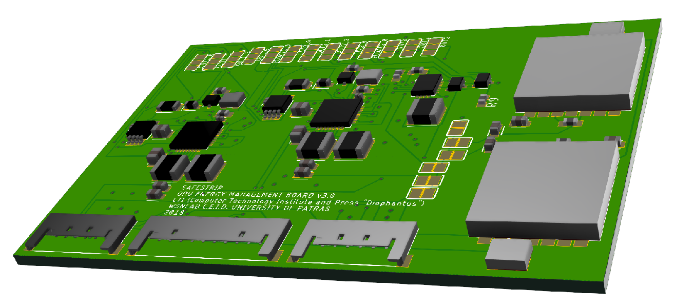
For the lab experiments conducted, the setup illustrated in Figure 10 was used. The main energy harvesting input that we used was a solar harvester. We chose the AMORTON 5902 (https://www.panasonic-electric-works.com/eu/amorton-amorphous-silicon-solar-cells.htm) outdoor solar cells from Panasonic with a nominal power of 150 mW. We created two pairs of panels, the two panels of each pair were connected in parallel and then the two pairs were connected in series, to increase both voltage and current output, ending with 600 mW of power. As energy storage unit we used rechargeable batteries. Four LIR2032 (https://www.powerstream.com/p/Lir2032.pdf) of 40 mAh capacity each were connected in parallel to acquire a total capacity of 160 mAh. The redundant energy source were non-rechargeable batteries, where we used the CR2430 (https://www.renata.com/fileadmin/downloads/productsheets/lithium/3V_lithium/CR2430.pdf) from Renata. Each non-rechargeable battery has a capacity of 300 mAh and we used four in parallel connection, coming up with 1200 mAh of total capacity. The LTC3331s are configured to charge the rechargeable batteries up to 4.2 V and disconnect them when they reach 3.2 V. The output was set to 3.3 V and the harvester window was set to power the output and charge the batteries when harvester’s voltage exceeds 6 V and switch to battery power when it goes under 5 V. A BLE module with embedded ambient sensors was powered from the energy management board, which required 3.3 V, 4 mA continuous current and 20 mA peak current during transmission. It transmitted once every second for 3.71 ms. A raspberry pi (3 B+) microcomputer with luminosity and voltage measuring sensors was programmed to measure the rechargeable, non-rechargeable, output and harvester’s voltage as well as the luminosity. The microcomputer also saved the timestamp of every wireless transmission it received from the mote. Data collected from the measurement sensors along with its timestamp was saved to a csv file. The mote, harvester and batteries were connected to the energy management board which is illustrated in Figure 11 as a 3D representation which also shows the solder-shorts used to select the various configurations of LTC3331.
The lab experiments were conducted for a period of one week. In Figure 12 it can be seen, that the energy management board was able to successfully power the mote using harvested energy during the day while also charging the batteries and switch to rechargeable batteries during the night. The relation between luminosity and solar harvester’s voltage is illustrated in Figure 12a. The harvester during the time of the day where the sun was directly above the panels produced almost 12 V, while the rest of the day was between 6 and 7 V. Figure 12b shows the average messages per second received from the mote, which shows that the mote was active for the duration of the experiment. As seen on the graph, the frequency we receive the messages varies while the output voltage is stable. This variation in the received messages occur due to the conditions of our experiments, where the mote with energy management board, harvesters and batteries had to be placed outside, with an enclosure made from polycarbonated plexiglass for their protection. The polycarbonated elements block RF transmissions resulting in a loss of messages. Our implementation combines the LTC3331 with the LTC4071 in order to charge faster the batteries, and is able to charge the batteries to their maximum capacity as seen in Figure 12c, when the harvester is producing the maximum power during the day. We also observe, that while the harvester is above 5 V, the rechargeable batteries are either charging or floating at their maximum voltage. However, after the harvester’s voltage falls under the lower threshold of 5 V, they begin to discharge until harvester’s voltage goes over the upper threshold of 6 V in the next day. Since the rechargeable batteries never reached the 3.2 V threshold, the non-rechargeable were never activated.
In order to evaluate the non-rechargeable batteries and the use of LTC3335 we conducted a second experiment for a small duration of 720 s. We completely removed the rechargeable batteries from the energy management board, and left connected just the harvester and the non-rechargeable batteries. We then disconnected the harvester in order to force the primary batteries to power the mote. The results of this short experiment are illustrated in Figure 13. We observe that the output voltage is close to 3.3 V (Figure 13b) while harvester’s voltage is at almost 10 V (Figure 13a). When the harvester is removed we notice that the output voltage is around 3.27 V, close to 3.3 V which is the target, and the non-rechargeable batteries begin to discharge (Figure 13c) as they provide power to the output. We then reconnected the harvester and the non-rechargeable batteries stopped powering the output as their voltage remained the same until the end of the experiment. We further observe that when the harvester is connected to the board again the non-rechargeable batteries voltage seems to increase a little. This increase is normal and can be described with the following equation where r is the battery’s internal resistance, R the equivalent series resistance and E the battery’s internal voltage. When no load is applied on the batteries R is too large compared to r which usually is a few m, that makes tend to 1 and as a result , while when a load is applied on the batteries the equivalent series resistance is less than when we measured the open cell voltage making the drop according to the value of R.
Similar to the simulation, the energy management board uses harvested energy to provide power to the output and charge the batteries while the harvester’s voltage is over the lower threshold of 5 V (6 V for the simulation). It switches to the rechargeable batteries when the harvester’s voltage is under the lower threshold or to the non-rechargeable when also the rechargeable are under their lower threshold to power the output. When harvester’s voltage is over the upper threshold, it switches to harvested energy to both power the output and charge the rechargeable batteries.
3.2.2. On Site
The second experiment is based on a real world scenario where an IoT device with sensors and communication modules is mounted on the road surface with suitable encapsulation. It offers helpful data for the users about environmental and road conditions, their position on the lane and their speed, while also providing the road operators with data about the road infrastructure (Figure 14b). Our goal is to efficiently provide power to this system for its uninterruptible operation.
Figure 14a shows the energy management board along with solar and piezolectric harvesters and the batteries. The configuration we followed here is a bit different than the one we used on the lab experiment. We used a total of eight solar panels, two of them were connected in series and placed on one of the LTC3331’s harvester’r input while the second input was used for the piezoelectrics. The piezoelectric elements we used as harvesters are the CEB-35D26 piezoelectric diaphragms, as we needed them to be under 3 mm in order to fit inside the encapsulation. The other six were connected to the second LTC3331 with the following configuration. Three and three connected in parallel and then in series. The total power output of the solar panels were 300 mW for the two panels and 900 mW for the six. The rechargeable batteries were increased to ten for a total capacity of 400 mAh and the non-rechargeable batteries were increased to six for a total capacity of 1800 mAh. The load on the output was the same mote used in the lab experiments. The experiment duration was fifteen days.
The procedure followed for these experiments is the same as with the lab experiments but with a different approach on the voltage measurement sensors since the previous one had 4–5 mA current draw on each voltage measured. Figure 15 shows the plots for the measurements. As illustrated in Figure 15a both solar harvester’s reach a maximum of 10 V, which is smaller than the maximum voltage reached in the lab experiments (Figure 12a) due to the resin filtering some of the UV radiation, while the harvester set with the six panels seems to be able to produce more voltage during the part of the day when the sun was not directly above the harvesters. The voltage output (Figure 15b) is at 3.3 V with an error of less than , which is acceptable as both LTC3331 and LTC3335 have an output error of and the mote required 3–3.6 V for its operation. The rechargeable batteries as illustrated in Figure 15c are charged daily to their maximum voltage, set by the configuration LTC3331 (4.1 V) while they discharge depending on the load of each day, from 3.6 V to 3.9 V. As in the lab experiments, the non-rechargeable batteries never activated due to the fact that the harvesters charged the rechargeable batteries every day to their maximum capacity. To further test the use of non-rechargeable batteries we covered the solar harvester with an opaque material to stop producing power. We then disconnected the rechargeable batteries (as it takes too long to get discharged in order to speed up the procedure). When the rechargeable batteries are disconnected, the non-rechargeable batteries begin to discharge as they provided power to the output. The voltage output, while it is powered by non-rechargeable batteries, is close to 3.3 V with an error of less than .
4. Discussion
In this work is presented an energy supply platform that incorporates, energy harvesting, hybrid energy storage and energy management intelligence. The platform offers fast battery charging, several battery security features such as extreme temperature cut off, overcharge and deep discharge protection. A simple low level hierarchical scheme of energy use is implemented, giving priority to harvested energy, then rechargeable batteries and if both fail to provide power to the output use non-rechargeable batteries. With the proposed configuration, the mote’s energy requirements and the specified batteries we have an estimated maximum uptime of the mote without using harvested energy of 192.75 h. The uptime was calculated using the following formula ), is 400 mAh, is 1800 mA, consumption is 4 mA and the and show the percentage of how much we can discharge each battery.
As future additions we want to integrate an ultra low power microcontroller that can provide information about energy harvesting, remaining battery capacity and power consumption so as better use of the platform can be implemented to extend the system operational time even more. We also plan to improve the design for the RF harvester as the power it offered in this implementation was very low and we were unable to measure it with the equipment we currently hold. Finally we want to examine the use of supercapacitors to further extend the energy storage pool.
5. Materials and Methods
This section includes the components used on the energy management board and the proposed circuit. We include Table 2 with the components (ICs, mosfets, diodes, capacitors, resistors, inductors and connectors) we used on our PCB and the corresponding quantity. We also include the schematic of the PCB in order to properly reproduce the proposed circuit (Figure 16).
Author Contributions
I.K. contributed in the design, the requirements and the final specifications of the system, I.T. implemented all the hardware activities and features, G.F. conducted all the experiments and simulations for the prototype’s evaluation and validation, and S.N. coordinated the whole activity and the main article editing. All the authors contributed in the writing of this work as well as the proof of reading process.
Funding
This work was supported by the General Secretariat for Research and Technology (GSRT), the Hellenic Foundation for Research and Innovation (HFRI) and the SAFE STRIP (safe and green sensor technologies for self-explaining and forgiving road interactive applications) project, which has received funding from the European Research Council (ERC) under the European Union’s Horizon 2020 research and innovation program (grant agreement n 723211).
Conflicts of Interest
The authors declare no conflict of interest.
References
- Tsenempis, I.; Filios, G.; Katsidimas, I.; Nikoletseas, S. Energy Harvesting and Smart Management Platform for Low Power IoT Systems. In Proceedings of the 2019 15th International Conference on Distributed Computing in Sensor Systems (DCOSS), Santorini Island, Greece, 29–31 May 2019; pp. 339–346. [Google Scholar]
- Cheng, Q.; Peng, Z.; Lin, J.; Li, S.; Wang, F. Energy harvesting from human motion for wearable devices. In Proceedings of the 10th IEEE International Conference on Nano/Micro Engineered and Molecular Systems, Xi’an, China, 7–11 April 2015; pp. 409–412. [Google Scholar]
- Naresh, B.; Singh, V.K.; Sharma, V.K. Flexible Hybrid Energy Harvesting System to Power Wearable Electronics. In Proceedings of the 2018 Fourth International Conference on Advances in Electrical, Electronics, Information, Communication and Bio-Informatics (AEEICB), Chennai, India, 27–28 February 2018; pp. 1–5. [Google Scholar]
- Obaid, A.; Hussain, F.; Fernando, X. Adaptive Switching for Efficient Energy Harvesting in Energy Constraint IoT Devices. In Proceedings of the 2017 IEEE 86th Vehicular Technology Conference (VTC-Fall), Toronto, ON, Canada, 24–27 September 2017; pp. 1–5. [Google Scholar]
- Prawiro, S.Y.; Murti, M.A. Wireless power transfer solution for smart charger with RF energy harvesting in public area. In Proceedings of the 2018 IEEE 4th World Forum on Internet of Things (WF-IoT), Singapore, 5–8 February 2018; pp. 103–106. [Google Scholar]
- Fabbri, D.; Pizzotti, M.; Romani, A. Micropower Design of an Energy Autonomous RF Tag for UWB Localization Applications. In Proceedings of the 2018 IEEE International Symposium on Circuits and Systems (ISCAS), Florence, Italy, 27–30 May 2018; pp. 1–5. [Google Scholar]
- Katsidimas, I.; Nikoletseas, S.; Raptis, T.P.; Raptopoulos, C. An algorithmic study in the vector model for Wireless Power Transfer maximization. Pervasive Mob. Comput. 2017, 42, 108–123. [Google Scholar] [CrossRef]
- Katsidimas, I.; Nikoletseas, S.; Raptopoulos, C. Power Efficient Algorithms for Wireless Charging under Phase Shift in the Vector Model. In Proceedings of the 2019 15th International Conference on Distributed Computing in Sensor Systems (DCOSS), Santorini Island, Greece, 29–31 May 2019; pp. 131–138. [Google Scholar]
- Katsidimas, I.; Kerimakis, E.; Nikoletseas, S. Radiation Aware Mobility Paths in Wirelessly Powered Communication Networks. In Proceedings of the 2018 Global Information Infrastructure and Networking Symposium (GIIS), Thessaloniki, Greece, 23–25 October 2018; pp. 1–7. [Google Scholar]
- Dai, H.; Ma, H.; Liu, A.X.; Chen, G. Radiation Constrained Scheduling of Wireless Charging Tasks. IEEE/ACM Trans. Netw. 2018, 26, 314–327. [Google Scholar] [CrossRef]
- Ongaro, F.; Saggini, S.; Mattavelli, P. Li-Ion Battery-Supercapacitor Hybrid Storage System for a Long Lifetime, Photovoltaic-Based Wireless Sensor Network. IEEE Trans. Power Electron. 2012, 27, 3944–3952. [Google Scholar] [CrossRef]
- Le, T.N.; Vo, T.P.; Duc, A.V.D. Plug-In Multi-source Energy Harvesting for Autonomous Wireless Sensor Networks. In Proceedings of the 2017 International Conference on Advanced Computing and Applications (ACOMP), Ho Chi Minh City, Vietnam, 29 November–1 December 2017; pp. 105–108. [Google Scholar]
- Smart, G.; Atkinson, J.; Mitchell, J.; Rodrigues, M.; Andreopoulos, Y. Energy harvesting for the Internet-of-Things: Measurements and probability models. In Proceedings of the 2016 23rd International Conference on Telecommunications (ICT), Thessaloniki, Greece, 16–18 May 2016; pp. 1–6. [Google Scholar]
- Deaconu, I.; Tudose, D.Ş. Sparrow: An energy harvesting wireless sensor node. In Proceedings of the 2017 4th International Conference on Control, Decision and Information Technologies (CoDIT), Barcelona, Spain, 5–7 April 2017; pp. 410–415. [Google Scholar]
- Dini, M.; Romani, A.; Filippi, M.; Bottarel, V.; Ricotti, G.; Tartagni, M. A Nanocurrent Power Management IC for Multiple Heterogeneous Energy Harvesting Sources. IEEE Trans. Power Electron. 2015, 30, 5665–5680. [Google Scholar] [CrossRef]
- Ferrari, M.; Ferrari, V.; Guizzetti, M.; Andò, B.; Baglio, S.; Trigona, C. Improved energy harvesting from wideband vibrations by nonlinear piezoelectric converters. Sens. Actuators A 2010, 162, 425–431. [Google Scholar] [CrossRef] [Green Version]
- Sari, I.; Balkan, T.; Kulah, H. An electromagnetic micro power generator for wideband environmental vibrations. Sens. Actuators A 2008, 145, 405–413. [Google Scholar] [CrossRef]
- Heo, S.; Yang, Y.S.; Lee, J.; Lee, S.; Kim, J. Micro energy management for energy harvesting at maximum power point. In Proceedings of the 2011 International Symposium on Integrated Circuits, Singapore, 12–14 December 2011; pp. 136–139. [Google Scholar]
- Powercast. Available online: https://www.powercastco.com/ (accessed on 29 March 2019).
- Analog Devices. Available online: https://www.analog.com/ (accessed on 10 June 2019).
Figure 1.
High level schematic of a mote including sensors, MCU and communication modules. The connection with the energy part is also depicted.
Figure 1.
High level schematic of a mote including sensors, MCU and communication modules. The connection with the energy part is also depicted.

Figure 2.
Abstract schematic of the mote’s energy module. Power management submodule has dual input (harvesters and batteries) single output and accepts parameters for its operation.
Figure 2.
Abstract schematic of the mote’s energy module. Power management submodule has dual input (harvesters and batteries) single output and accepts parameters for its operation.

Figure 3.
Typical application of the LTC3331 ([20]) using a solar panel and a piezo energy harvester to provide 1.8 to 5 V to the output and charge a single cell Li-Ion battery.
Figure 3.
Typical application of the LTC3331 ([20]) using a solar panel and a piezo energy harvester to provide 1.8 to 5 V to the output and charge a single cell Li-Ion battery.

Figure 4.
LTC3331 combined with LTC4071 to allow more charging current to the rechargeable batteries.
Figure 4.
LTC3331 combined with LTC4071 to allow more charging current to the rechargeable batteries.

Figure 5.
Priority is given to harvested energy and rechargeable over non-rechargeable batteries utilizing the PGVOUT signal of each LTC3331.
Figure 5.
Priority is given to harvested energy and rechargeable over non-rechargeable batteries utilizing the PGVOUT signal of each LTC3331.

Figure 6.
Flowchart that depicts the hierarchy scheme of the harvested energy over batteries and the corresponding priority of the rechargeable batteries over non-rechargeable.
Figure 6.
Flowchart that depicts the hierarchy scheme of the harvested energy over batteries and the corresponding priority of the rechargeable batteries over non-rechargeable.

Figure 7.
High level schematic of our proposed energy management module. It contains the two LTC3331 with the LTC4071 as the external charger, the LTC3335 and the prioritizer we implemented.
Figure 7.
High level schematic of our proposed energy management module. It contains the two LTC3331 with the LTC4071 as the external charger, the LTC3335 and the prioritizer we implemented.

Figure 8.
Schematic from the simulation of the combination of LTC3331 with the LTC4071 to increase the charging current for the rechargeable batteries.
Figure 8.
Schematic from the simulation of the combination of LTC3331 with the LTC4071 to increase the charging current for the rechargeable batteries.

Figure 9.
Transient analysis of LTC3331 combined with LTC4071 for 500 ms duration. (a) Harvester, battery, output voltage and EH_ON signal. (b) Battery voltage and current flowing through AC1 and BAT_IN pins. (c) Harvester and output voltage and current flowing through BAT_IN pin.
Figure 9.
Transient analysis of LTC3331 combined with LTC4071 for 500 ms duration. (a) Harvester, battery, output voltage and EH_ON signal. (b) Battery voltage and current flowing through AC1 and BAT_IN pins. (c) Harvester and output voltage and current flowing through BAT_IN pin.

Figure 10.
Lab setup for experiments. Energy management board, sensor mote, solar cells, rechargeable batteries and non-rechargeable batteries.
Figure 10.
Lab setup for experiments. Energy management board, sensor mote, solar cells, rechargeable batteries and non-rechargeable batteries.

Figure 11.
A 3D model of the PCB we designed for our proposed circuit.

Figure 12.
Results from a seven day evaluation of our energy management board. (a) Solar cells voltage according to the applied luminosity. (b) Average messages received per second from the mote. (c) Rechargeable and non-rechargeable battery voltage.
Figure 12.
Results from a seven day evaluation of our energy management board. (a) Solar cells voltage according to the applied luminosity. (b) Average messages received per second from the mote. (c) Rechargeable and non-rechargeable battery voltage.

Figure 13.
Results from a short evaluation of our board to demonstrate the robust switch from harvesters to non-rechargeable batteries and vice versa.
Figure 13.
Results from a short evaluation of our board to demonstrate the robust switch from harvesters to non-rechargeable batteries and vice versa.

Figure 14.
(a) The energy management board encapsulated in resin along with the harvesters and batteries for use on road infrastructure; (b) IoT device with sensors and communication modules, mounted on the road surface with suitable encapsulation. The energy part is the one closer to the side of the road.

Figure 15.
Results from an evaluation of the energy management board encapsulated in resin for the duration of 15 days. (a) Solar panels voltage. Solar 1: 2 panels, Solar 2: 6 panels. (b) Output voltage. (c) Rechargeable and non-rechargeable battery voltage.
Figure 15.
Results from an evaluation of the energy management board encapsulated in resin for the duration of 15 days. (a) Solar panels voltage. Solar 1: 2 panels, Solar 2: 6 panels. (b) Output voltage. (c) Rechargeable and non-rechargeable battery voltage.

Figure 16.
Detailed schematic of the proposed energy management prototype.


Table 1.
Table with the pins we used to implement the charger.
| Pin Name | Function |
|---|---|
| Rectified input voltage | |
| CHARGE | Enable charging of the battery |
| BAT_OUT | Output side of the battery disconnect switch |
| BAT_IN | Input for the battery |
Table 2.
Table with the components used on the energy management board PCB.
| Component Name/Value | Quantity |
|---|---|
| LTC3331 | 2 |
| LTC4071 | 2 |
| LTC3335 | 1 |
| P2110B | 2 |
| MCH3383 | 4 |
| DMG6968U | 2 |
| CMOSH-3 TR | 2 |
| 0.1 uF | 4 |
| 1 uF | 2 |
| 4.7 uF | 1 |
| 22 uF | 8 |
| 196 | 2 |
| 10 k | 3 |
| 100 k | 4 |
| 5.6 M | 2 |
| 22 uH (LPS3314) | 3 |
| 330 uH (LPS3314) | 2 |
| Picolock 10 | 1 |
| Picolock 6 | 2 |
© 2019 by the authors. Licensee MDPI, Basel, Switzerland. This article is an open access article distributed under the terms and conditions of the Creative Commons Attribution (CC BY) license (http://creativecommons.org/licenses/by/4.0/).
Share and Cite
MDPI and ACS Style
Filios, G.; Katsidimas, I.; Nikoletseas, S.; Tsenempis, I. A Smart Energy Harvesting Platform for Wireless Sensor Network Applications. Information 2019, 10, 345. https://doi.org/10.3390/info10110345
AMA Style
Filios G, Katsidimas I, Nikoletseas S, Tsenempis I. A Smart Energy Harvesting Platform for Wireless Sensor Network Applications. Information. 2019; 10(11):345. https://doi.org/10.3390/info10110345
Chicago/Turabian StyleFilios, Gabriel, Ioannis Katsidimas, Sotiris Nikoletseas, and Ioannis Tsenempis. 2019. "A Smart Energy Harvesting Platform for Wireless Sensor Network Applications" Information 10, no. 11: 345. https://doi.org/10.3390/info10110345
Note that from the first issue of 2016, this journal uses article numbers instead of page numbers. See further details here.