Abstract
Apache Spark is a high-speed computing engine for processing massive data. With its widespread adoption, there is a growing need to analyze its correctness and temporal properties. However, there is scarce research focused on the verification of temporal properties in Spark programs. To address this gap, we employ the code-level runtime verification tool UMC4M based on the Modeling, Simulation, and Verification Language (MSVL). To this end, a Spark program S has to be translated into an MSVL program M, and the negation of the property P specified by a Propositional Projection Temporal Logic (PPTL) formula that needs to be verified is also translated to an MSVL program M1; then, a new MSVL program “M and M1” can be compiled and executed. Whether program S violates the property P is determined by the existence of an acceptable execution of “M and M1”. Thus, the key issue lies in how to formalize model Spark programs using MSVL programs. We previously proposed a solution to this problem—using the MSVL functions to perform Resilient Distributed Datasets (RDD) operations and converting the Spark program into an MSVL program based on the Directed Acyclic Graph (DAG) of the Spark program. However, we only proposed this idea. Building upon this foundation, we implement the conversion from RDD operations to MSVL functions and propose, as well as implement, the rules for translating Spark programs to MSVL programs based on DAG. We confirm the feasibility of this approach and provide a viable method for verifying the temporal properties of Spark programs. Additionally, an automatic translation tool, S2M, is developed. Finally, a case study is presented to demonstrate this conversion process.
1. Introduction
With the continuous development of the Internet, the amount of data we can collect is also expanding. How to deal with these increasing data has aroused extensive research and attention. Among them, Hadoop [1,2] and Spark [3,4] computing engines show their unique advantages in data processing.
MapReduce [5,6] is a distributed parallel computing technology. The cores of Hadoop are the MapReduce computing framework and the distributed file system HDFS [7]. In terms of processing tasks, MapReduce segments input data, constructs Map tasks for each segment, and submits them for processing. Data in the partition are transferred to the Map function as key–value pairs, and processed pairs are saved as intermediate results on disk. This characteristic results in Hadoop spending considerable time on complex data processing. Spark is a fast, universal and scalable big data analysis and computing engine based on memory. It is developed on the basis of Hadoop. One of its design goals is to avoid frequent calls to disk I/O operations. For this purpose, a basic data processing model called Resilient Distributed Datasets (RDD) is specially designed. In the process of calculation, data are cached in memory. Only when the memory capacity is insufficient are data are cached on a disk. Spark provides a series of operations for RDD, including not only Map() and Reduce() operations but also filter(), flatMap(), groupBy(), sortBy() and other operations, which can provide developers with rich choices. It also supports APIs in Java, Python, Scala, R and other languages, enabling developers to quickly build different applications.
In the era of information explosion, the widespread application of big data has become a crucial force shaping the future [8]. With the continuous growth of big data volumes, ensuring the correctness and temporal properties of big data has become particularly critical. Big data not only encompasses vital information across various industries, from finance to healthcare, but also involves the processing of these data often tied to crucial business decisions and personal privacy. Therefore, the precise validation of big data, especially the verification of its temporal properties such as timeliness, reliability, and consistency, becomes paramount. This paper aims to delve into the correctness validation and temporal property verification of Spark applications, which may be the most widely used solution among big data processing applications.
The runtime verification tool UMC4M [9,10] uses a program M written in the Modeling, Simulation, and Verification Language (MSVL) [11,12,13,14] with the expected property P specified by the Propositional Projection Temporal Logic (PPTL) [15,16] formula as input. Whether M violates the property P is determined by whether there is an acceptable execution of a new MSVL program “M and M1”, where the M1 is the negation of the property P [17,18]. In order to use the tool UMC4M to verify the temporal properties of Spark programs, it is necessary to use MSVL to formalize Spark programs. MSVL is a parallel programming language, which can be easily used for parallel computing. In [19], we merely proposed a formalization method using MSVL for Spark applications but did not implement it. Here, we formalize Spark programs by writing MSVL functions corresponding to RDD operations and extracting the execution relations of these functions based on the Directed Acyclic Graph (DAG) of Spark programs. This transformation converts a Spark program into a logically equivalent MSVL program, shifting the verification of properties in the Spark program to the verification of the MSVL program.
The contributions of this paper are three-fold:
- (1)
- For RDD operations, we write corresponding MSVL functions to realize its processing of data. In addition, for those RDD operations with wide dependencies, we also write specialized Shuffle functions to complete the exchange of data between the two stages.
- (2)
- We propose an algorithm for converting Spark programs to MSVL programs based on the DAG of Spark programs. The algorithm extracts formal relations within stages and formal relations between stages, respectively, thus completing the transformation of a Spark program into an MSVL program.
- (3)
- Based on the algorithm mentioned above, we develop an automatic translation tool S2M to convert Spark programs to MSVL programs and give a case study to show the conversion process.
The rest of the paper is organized as follows. Section 2 provides a brief introduction to research related to big data security and formalization and illustrates the advantages of using UMC4M to verify timing properties. Section 3 briefly introduces MSVL and the Spark framework. In Section 4, we describe the implementation of program translation system. In Section 5, a case study is given. Section 6 is a technical discussion of the methodology. Section 7 concludes the paper.
2. Related Work
The research on the validation correctness of big data applications is very important, especially for Spark applications, but there is little relevant research on this aspect.
Luo et al. [20] introduced an approach to predict the performance of Spark based on its configuration parameters using machine learning, specifically Support Vector Machine (SVM). This research focuses on understanding the impact of Spark’s numerous configuration parameters and their interactions on performance. Additionally, Artificial Neural Network (ANN) is employed to model Spark’s performance, and the paper reports that the SVM outperforms ANN.
Grossman et al. [21] proposed an SMT-based technique to verify the equivalence of interesting classes in Spark programs. By modeling Spark programs, they demonstrated the undecidability of checking equivalence even for Spark programs with a single aggregation operator. They also proved the completeness of the technique under certain restrictions.
Beckert et al. [22] proposed a method by dividing equivalence proof into equivalence proof sequences between intermediate programs with small differences for equivalence proof between imperative and MapReduce algorithms, and they verified the feasibility of the method on k-means and PageRank algorithms.
Yin et al. [23] formalized the main components of Spark on YARN using Communicating Sequential Processes (CSP). Then, they input the model into model checker Failures Divergence Refinement (FDR) to verify their main properties, such as Divergence Freedom, Load-Balancing, Deadlock Freedom and Robustness.
Baresi et al. [24] proposed a method based on model checking for verifying the execution time of Spark applications, and the method has been validated on some realistic cases.
de Souza Neto et al. [25] introduced TRANSMUT-SPARK, a tool designed to automate mutation testing for Big Data processing code within Spark programs. The complexity of Spark code makes it susceptible to false statements that require thorough testing. They explored the application of mutation testing, a fault-based technique, in Spark programs to automatically evaluate and design test sets.
However, these efforts have not verified the temporal properties that Spark applications should meet. At present, there are some tools for verifying temporal properties. Compared with the most relevant software model detection tools LTLAutomizer [26] and T2 [27,28,29], UMC4M has the following advantages: (1) the input of the UMC4M tool is a program written in the MSVL function, and the PPTL formula describes the properties to be verified. MSVL and PPTL are subsets of the Projection Temporal Logic (PTL), which leads to higher efficiency in program validation. (2) PPTL is capable of expressing fully regular properties, demonstrating greater expressive power than Linear Temporary Logic (LTL) and Computing Tree Logic (CTL).
3. Preliminaries
This section provides a brief introduction to the fundamental principles of MSVL and Spark.
3.1. MSVL
Modeling, Simulation and Verification Language (MSVL) is developed from the Framed Tempura [30] and is an executable subset of the Projection Temporal Logic (PTL) [12]. The arithmetic and Boolean expressions of MSVL can be summarized and defined as shown in Equations (1) and (2), which are used in MSVL statements.
where c is a constant, and x is a variable. represents the next state of variable e, and represents the previous state of variable e. is the call of the state function g. Each arithmetic operation(+|-|*|/) can be regarded as a function call . is a call to an external function. b is a boolean expression that can be either true () or false (). It may also be the negation () of another boolean expression, the logical AND () of two boolean expressions, or the equality comparison () or less-than comparison () between two arithmetic expressions. The MSVL language includes the fundamental constructs as shown in Table 1, and by combining them according to certain rules, one can generate MSVL programs.

Table 1.
The statements of MSVL.
MSVL supports not only common statements in the imperative language such as assignment loop conditional statements, sequential statements and while statements, but also non-deterministic and concurrent statements. For example, indicates that 0 is immediately assigned to variable x, while indicates that 0 is assigned to in the next state and the length of interval is one unit. ; represents the statement that can only be executed after the completion of statement. means that the execution can only be continued when condition b is satisfied [31]. In addition, in order to improve the efficiency of programming, MSVL supports calling the library functions of C language, such as fopen(), fgets() and other functions. The function structure of MSVL is function . The structure also allows us to write functions that are logically equal to RDD operations [14]. At the same time, we also have the model checker UMC4M [9] for verifying MSVL programs.
3.2. Spark Framework
The core of the Spark framework is a computing engine. On the whole, it adopts the standard master–slave structure, in which the master node is responsible for managing the scheduling of tasks in the whole cluster, and the slave nodes are responsible for the actual execution of tasks. As the core model of data processing in the Spark framework, RDD supports two types of operations: one is transformation operations, such as map(), flatMap(), groupBy(), filter() and reduceByKey(), and the other is action operations, such as reduce(), collect(), foreach() and take(). There are dependency relationships between RDDs, which can be divided into narrow dependencies and wide dependencies. Spark forms a DAG based on the dependencies between RDDs. The DAG is submitted to the DAGScheduler, which divides the DAG into multiple stages of interdependence. When encountering a wide dependency, a stage is generated, and each stage contains one or more tasks. Then, these tasks are submitted to the TaskScheduler for running in the form of taskSet.
The running framework of Spark, as shown in Figure 1, includes the Cluster Manager, Worker Nodes running multiple job tasks, Driver Nodes for the task control of each application, and Executor processes on each Worker Node responsible for the specific task execution.
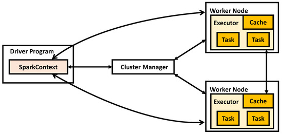
Figure 1.
Spark running framework.
The Driver runs the main function of the Spark application and creates the SparkContext. The SparkContext is responsible for communication with the Cluster Manager, handling tasks such as resource acquisition, task assignment, and monitoring.The Cluster Manager is responsible for requesting and managing the resources needed to run the application on Worker Nodes. The Executor is a process running on a Worker Node where the application is executed. It is responsible for running tasks and storing data in memory or on disk.
A Spark application is divided into jobs, stages and tasks. Their definitions are given as follows:
- (1)
- Application: a Spark application written by the user contains one or more jobs.
- (2)
- Job: a set of stages executed as a result of an action operation. During the execution of a Spark application, each action operation triggers the creation and submission of a job.
- (3)
- Stage: a set of tasks that perform the same computation in parallel based on partitions of input data.
- (4)
- Task: unit of execution in a stage. A task is a single data processing on a data partition.
In different cluster environments, the process of Spark submission is basically the same. The driver starts to execute the main function after all the executors are registered. When it executes an action operation, it triggers a job and starts to divide the stages according to the wide dependencies. Each stage generates the corresponding taskSet, and then the driver distributes tasks to the specified executors for execution.
There are two kinds of RDD operations in Spark: namely, transformation operations and action operations. The transformation operations refer to the operation of creating a new RDD from the existing RDD and returning the new RDD. The transformation operations are lazily evaluated. They do not immediately trigger the execution of the actual conversion and only records the conversion relationship between RDDs. Only when an action operation is triggered can the transformation operations be truly executed and the calculation result be returned. Spark submits the operator graph to the DAGScheduler when an action operation is called. DAGScheduler divides DAG into stages according to wide dependencies. The dependencies between RDDs can be divided into narrow dependencies and wide dependencies, as shown in Figure 2. Narrow dependencies mean that a partition of each parent RDD is used by at most one partition of the child RDD. Wide dependencies mean that each partition of the parent RDD can be used by multiple partitions of the child RDD, which are also known as shuffle dependencies.
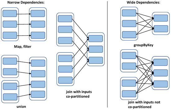
Figure 2.
Dependency types.
4. Translation from Spark to MSVL
In this section, we realize the translation from Spark programs to MSVL programs and introduce it from the aspects of data storage, function translation and DAG-based formalization.
4.1. Data Storage Structure
RDD is the most basic data processing model in Spark. Spark provides rich transformation and action operations for RDD. The data in the RDD can only be updated through the transformation operations to generate a new RDD based on the original RDD. The data set in the RDD is logically and physically divided into multiple partitions. In a stage, one partition of the parent RDD is used by at most one partition of the child RDD, and the partitions in an RDD execute a series of transformation operations in parallel. The data in each partition can be executed in a separate task. The number of partitions and the number of tasks correspond one to one.
MSVL supports multiple data types to build data structures. Based on the Spark RDD data feature, we can use the MSVL-type struct to build special data structures for storing data. We define two structures, ReadData and KeyValue, to process data in the read stage and non-read stage, respectively, where the read stage refers to the stage containing the textFile operation.
struct ReadData { char *data[10] and int value[10] and int order }; struct KeyValue { char *data and int value and int order }; |
In the struct ReadData, data[0] is used to store a line of data read from the data file. When data[0] is handled by the split function, data[0] is split, and the split data are saved in data[i] (0 ≤ i < 10). Here, data[0] is used to avoid memory waste. For the key–value pairs type in Spark, we define the array value to store the number of data occurrences. In a stage, data are processed in a pipeline way. To this end, we define an order to represent which function processes the data. For the non-read stage, the main task is to complete the data operation. To achieve that, we define the structure KeyValue, where data is used to store data, value represents the number of data occurrences, and order represents which function processes the data. Partitions in an RDD are executed in parallel. To this end, we define two arrays struct ReadData lineData[N] and struct KeyValue finaldata[M] for the read stage and non-read stage, respectively. Here, N and M are both integer constants, which are typically chosen to be slightly larger than the parallelism of the function. This choice aims to prevent any impact on the parallelism of the function and the size of the transformed program.
Stages are divided according to wide dependencies. That is to say, a shuffle occurs in two directly connected stages. Shuffling can cause data disruption and reorganization. For the conversion of data between directly connected stages A and B, we define structures CollectData and PrepData, where CollectData is used to collect the processed data in stage A and PrepData is used to preprocess the data for the next stage B.
struct CollectData { char *data and int value and int idle }; struct PrepData { char *data and int value[100] and int idle }; |
The struct CollectData is used to complete data collection. In the struct CollectData, data is used to store data, value represents the number of data occurrences and idle represents the status of memory, where idle = 0 means the memory is free, and idle = 1 means that the data have been stored but not used. The struct PrepData is used to complete data preprocessing. In the struct PrepData, data is used to store data, and array value is used to store the number of the respective occurrences of the same data. idle also indicates the status of the memory. We define two arrays, struct CollectData end_Data1[L] and struct PrepData end_Data[L], to complete data collection and preprocessing separately, where L is a constant and is usually set to the largest possible number to avoid some data not being collected.
4.2. Translation from Spark Operations to MSVL Functions
The RDD operations are divided into two types: transformation operations and action operations. The action operations actually calculate the dataset, which are the basis for Spark to divide jobs. Stages are divided according to wide dependencies. In a stage, the partitions in an RDD are processed in parallel. MSVL not only supports function definitions and statements that are similar to imperative languages, such as assignment, condition, and loop statements, but it also supports non-deterministic and concurrent programming, such as selection and parallelism statements. This means that corresponding MSVL functions can be written for Spark RDD operations. Most operational translation ideas are the same. First, the execution condition is evaluated, and then the internal logic is executed when the conditions are met. Due to space constraints, we briefly introduce the translations of several operations here.
4.2.1. Translation of textFile Operation
During the execution of an MSVL program, if it encounters C language library function calls, the MSVL interpreter automatically calls the corresponding C functions and returns the execution result. Thus, when writing the function corresponding to textFile operation, we can call C functions such as fopen(), fclose(), fgets(), etc. The operation is a transformation operation that reads data from a file as a collection of lines. Function 1 shows the MSVL function corresponding to textFile operation.
MSVL Function 1: ReadWords(char *) |
1 frame() and 2 ( 3 FILE* fopen(, “r”) and skip; 4 int 0, 0 and skip; 5 while (feof() = 0){ 6 0; 0; 7 await( = 1 OR ⋯ OR = 1); 8 while ( N AND = 0){ 9 if( = 1) then { 1}else { + 1} 10 }; 11 fgets() and skip; 12 + 1 13 }; 14 1 15 ) |
The MSVL function is the first function executed. The function reads data from file . When there is an idle memory, i.e., (0 ≤ i < N), at most one line of characters is read from the file and stored in , where is a global constant, and then the is added by 1, which indicates that the data are ready to be executed by the second function. This process is repeated until the file is read completely (Lines 5–13). After reading all data, the global variable is set to 1, indicating that the has been completely read (Line 14).
4.2.2. Translation of Shuffle
A job consists of multiple stages, and each stage has multiple transformation operations. The transformation operations are categorized into two types based on their dependencies: narrow transformations and wide transformations. Wide transformations are the basis of stage division. It means that each partition of the parent RDD can be used by multiple child RDD partitions, and a partition of each child RDD usually uses all parent RDD partitions. This property of wide transformations results in shuffling, which refers to shuffling the data between stages. For this reason, we define the shuffle function of MSVL based on its properties to handle data shuffling between two stages. Although the data types processed in different stages are different, the principle remains the same. We present the function in the read stage in Function 2.
MSVL Function 2: shuffle(int , char ) |
1 frame() and 2 ( 3 int 0, 0 and skip; 4 while(1 OR⋯OR 1 OR 5 await( OR ⋯ OR = ); 6 0; 0; 7 while ( AND = 0){ 8 if( = ) then { 1} else { + 1} 9 }; 10 Collect(i); 11 1; 12 }; 13 Pretreat(); 14 0; 15 0 16 ) |
In Function 2, indicates the number of operations in the current stage plus 1, and represents the name of the first operation in the next stage. The data in (0 ≤ i < N) in the current stage are collected by the function after processing, and then is set to 1. This process is repeated until all data in the current stage are processed (Lines 4–12). After collection, the collected data are preprocessd by the function (Line 13). The data preprocessing function differs for different wide transformations. For example, for the operation, the data are aggregated, and these data with the same key are stored in (0 ≤ j < L). The values corresponding to the same key are saved in array of array . Finally, we set both and to 0 (Lines 14–15), where the global variable indicates the reading position of array in the next stage.
4.2.3. Translation of reduceByKey Operation
The is a wide transformation operation, and its function signature is . The operation aggregates values with the same key based on the anonymous function passed in and returns a new RDD. We use MSVL statements to write the corresponding function based on the characteristics of the operation. The function is not executed until the function completes data preprocessing.
MSVL Function 3: ReduceByKey(int n) |
1 frame() and 2 ( 3 int 0, 0 and skip; 4 while ( = 0){ 5 Bakery(); 6 await( = 1 OR ⋯ OR = 1 OR =1); 7 0; 0; 8 while ( AND = 0){ 9 if( = 1 AND = 0) then { 1}else { + 1} 10 }; 11 1; 12 reduceImplicit(); 13 + 1; 14 0 15 }; 16 ) |
The code for the function is shown in Function 3. As this operation has wide dependencies, the function is executed first in the current stage. When the functions are executed in parallel, in order to prevent the same functions from performing the same processing on (0 ≤ i < M) and obtain mutually exclusive access to global variable , we use the algorithm and array to implement it. The is used for locking, where n represents the function ID, array is a global variable that represents the queue number, and array is also the global variable that represents whether the number is being retrieved (Line 5). When there is a free memory block ( = 1 (0 ≤ i < M)) and the data block is not locked by a function ( = 0), the data block is locked by the function (Line 11) and data processing is performed through the function . After processing is completed, we add 1 to and unlock the locked data . This process is repeated until array is fully read (Lines 4–15).
MSVL Function 4: reduceImplicit(int , int n) |
1 frame() and 2 ( 3 int , 0 and skip; 4 ; 5 + 1; 6 0; 7 if(=1)then{ 8 ; 9 while( 0){ 10 + ; 11 + 1 12 }; 13 0 14 }else{ 15 1 16 } 17 ) |
For different anonymous functions, we automatically generate corresponding reduceImplicit functions. Taking the anonymous function (_+_) as an example, we generate as shown in Function 4. In Function 4, the parameter represents which data are processed, and the parameter n represents the ID of the function. We use to save the value of , where is a global variable representing which element in array is read (Lines 4–5). Then, we unlock these resources (Line 6). If the data to be read from array exist, the data in are saved in , and values are aggregated and saved in . Then, the of the data is set to 0 (Lines 7–13). If the data to be read from array do not exist, the global variable is set to 1, indicating that array has been completely read (Lines 14–16).
4.3. DAG-Based Formalization
When an action operation is performed, a new DAG is generated. Each operation generates a new RDD. The original RDD forms a DAG after a series of transformations. According to the different dependency relationships between RDDs, the DAG can be divided into different stages. To formalize Spark programs based on the DAG, we have developed a tool called S2M, whose architecture is shown in Figure 3. The formalization process for Spark programs based on the DAG consists of four main steps: extraction of required information, formalization of operations within stages, formalization between stages, and function replacement and supplementation.
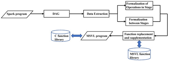
Figure 3.
Architecture of S2M.
4.3.1. Data Extraction
This section is mainly about extracting the information between RDD operations in stages and the information between stages from the DAG of a Spark application. We use Python to implement the extraction for obtaining the required information from the SVG tag in the DAG UI interface of the application.
In a DAG, each blue rectangle corresponds to a Spark operation, and the nodes in each rectangle represent the RDDs created under the corresponding operation. The RDDs are connected by arrows. For each stage in a DAG, we need to extract the name of operation and nodes in each blue rectangle as well as the nodes connected by the arrows connecting blue rectangles (operations). Each blue rectangle may have one or more nodes. For each stage, we define an array where each element holds a blue rectangle information, and the element is stored in tuple , where the first element in the tuple is the name of the operation and the second element called is the set of nodes. For arrows in a stage, we construct an array to store the nodes connected by the arrows connecting blue rectangles. The elements are stored in tuples . For information extraction between stages, we construct an array to store the connecting nodes of the arrows connected between stages. The elements are also stored in the format of . In addition, we create an array to save the number of lines in the code file for each operation in the DAG. This allows us to extract the anonymous functions in each incoming operation.
4.3.2. Formalization of Operations in Stages
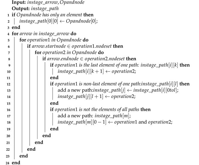
To extract the formalization of operations within a stage, we first obtain the execution paths in the stage, where a path refers to the order of operations execution directly connected by arrows. Then, we process these paths to complete the formalization of RDD operations in the stage.
After we obtain the name and nodes of each operation (blue rectangle) in a stage, as well as the nodes connected by the arrows connecting RDDs, we determine the two operations that are directly connected by determining which operation the and of an arrow are in. The acquisition of execution paths during a stage is presented in Algorithm 1, where each element in is an execution path in a stage. If there is only one operation in a stage, this operation is added to a path (Lines 1–3). Then, we access each arrow of connection operations (Line 4) and look for the operations where the and of the arrows are located (Lines 5–8). There are three situations at this time: the first is if the operation (operation1) where is located is the last element in a path; then, the operation (operation2) where is located is directly added to that path (Lines 9–11). The second is if is not the last element in a path; then, we copy the path from the beginning to to a new path and add to the new path (Lines 12–16). The third is if is not in any paths; then, a new path is added and we add both and to this path (Lines 17–21).
| Algorithm 1: Execution paths of RDD operations in a stage |
 |
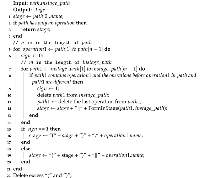
To formalize operations within a stage, we process the execution paths in that stage. Algorithm 2 outlines this process, where is the first path of , stores all paths obtained through Algorithm 1, and stage stores the formalization of operations in a stage. Firstly, we assign the name of the first operation in the first path() to the stage, and if there is only one operation in , we exit the function directly (Lines 1–4). Then, we sequentially access the remaining operations () in (Line 5). For each accessed, we access other paths to find the path () containing this , and these two paths are different in the part before . If such a path exists, we remove it from all paths () and perform the same processing on the parts of the path before . After processing is completed, these two paths are parallel in the parts before (Lines 7–14), and is executed only after these paths are executed (Lines 15–17). If such a path does not exist, and the previous operations are executed in parallel (Lines 18–20). After visiting the first path, we obtain the formal relationships within the stage.
| Algorithm 2: FormInStage( |
 |
4.3.3. Formalization between Stages
The formalization between stages is similar to the formalization of operations in a stage. First, we need to obtain the paths between directly connected stages and then process these paths to achieve formalization between stages. For obtaining paths between stages, we first define an array to hold the execution paths between stages, where each element in is an array representing a sequential execution path between stages. Then, we process the connecting arrows between stages stored in , where each element connects two directly connected stages. The process is similar to Algorithm 1, which sequentially traverses each arrow in . For the two stages of arrow connection (), if there is a path in that contains and is the last element of the path, is added to the end of the path. If there is a path in that contains and is the first element of the path, is added to the first element of the path. For other situations, we add a new path and sequentially add and . After processing all arrows between stages, we obtain the sequential execution paths between stages and store it in .
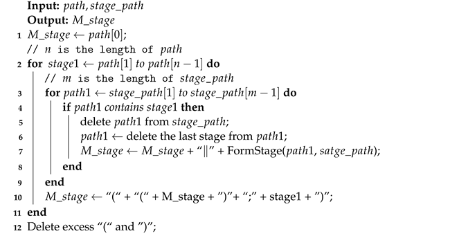
After we obtain the execution paths between stages, we process them to achieve formalization between stages, as shown in Algorithm 3, where is the first path in . Firstly, we assign the first stage in to the output (Line 1). Then, we sequentially access each stage () in (Line 2). For each , we search for other paths that also contain . If such paths exist, paths before are parallel, and we also perform recursive operations on paths (Lines 3–9). After processing paths containing , the execution relationship between and the previous one is sequential (Line 10). Finally, we remove parentheses that do not affect the execution order (Line 12).
| Algorithm 3: FormStage() |
 |
4.3.4. Function Replacement and Supplementation
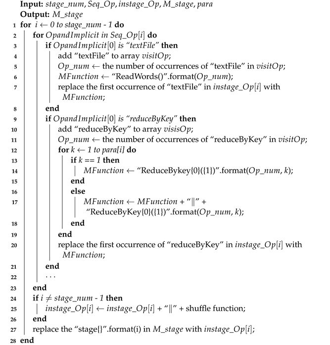
Because the same operation may occur multiple times, the internal processing logic may also differ. Therefore, we need to differentiate them by assigning different names to operations that may occur multiple times. In addition, operations in the same stage are executed in parallel, so we need to parallelize the transformed MSVL function and set its ID. One example is the MSVL function Map() corresponding to the map operation: we process it as Map(1) ‖⋯‖ Map(n), where n represents the ID of the function. Additionally, for each wide transformation operation, we add a function before the MSVL function to complete data collection and preprocessing, as shown in Algorithm 4.
In Algorithm 4, is the number of stages. stores the operation names and anonymous functions for each stage after formalization. stores the formalization of operations in each stage. stores formalization between stages. The array para stores the parallelism of all stages. The format method is used to format strings. We process the formalized operations in each stage (Lines 1–2). If this operation is , we add it to the array , which records the processed operations. Then, we check the number of times the operation has already occurred, change the MSVL function corresponding to the operation based on the number of occurrences, and replace the operation in the formalization of operations of this stage (Lines 3–8). If this operation is , the is added to the array and the number of occurrences is recorded. Then, we perform parallel processing on the corresponding MSVL function based on the parallelism of this stage, replacing the operation with parallelized MSVL function in the formalization of operations of this stage (Lines 9–21). After formalizing a stage, we add the corresponding shuffle function based on the wide dependency operation of the next stage connected to it (Lines 24–26), and we replace the corresponding stage in the formalization of the stage with the formal operations of this stage after processing (Line 27).
| Algorithm 4: Formalization of Spark programs |
 |
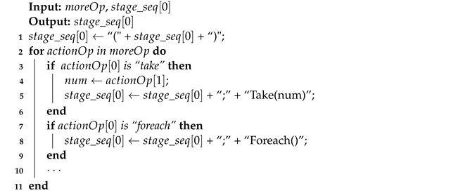
When an action operation is encountered, a job submission is triggered, and the Driver program submits the job to the DAGScheduler, which constructs the job into a DAG. However, in a program, two action operations may occur in succession, and we need to specifically handle such cases. To address this, we need to determine where the action operations in the DAG are located in the program. For subsequent action operations, we use sequential construction to formalize them, as shown in Algorithm 5. The variable stores action operations that have not yet been added to DAGs, where each element stores the name and anonymous function of an action operation. and are MSVL functions corresponding to the action operations take and foreach, respectively.
| Algorithm 5: Supplement to the MSVL |
 |
5. Case Study: TopN
In this section, we demonstrate our work by implementing the analysis of click stream log data using Spark. Subsequent sections provide a detailed description of the translation process. We established a Spark cluster environment with five cores using virtual machines. By executing a TopN case, we obtained its Directed Acyclic Graph (DAG). The SVG label information of the DAG was input into the S2M tool to formalize the TopN program.
5.1. Application Programs
The aim of this case study is to analyze clickstream log data using Spark and find the top five URLs with the most visits. Figure 4 displays the Scala code for the TopN application.
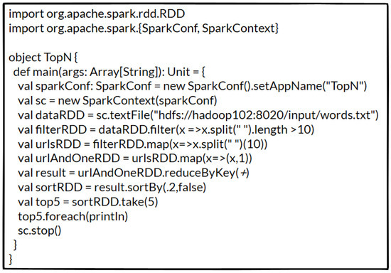
Figure 4.
Code of TopN application.
The application begins by reading data from the hdfs text file. The variable dataRDD stores multiple lines of text content after the operation is executed. Next, we filter out any dirty data in using , where is a lambda expression where the left side is the parameter and the right side is the function to be executed by the lambda. means that the data are divided according to spaces, and when the length of the divided data is greater than 10, it is retained in the . We then use to traverse every data item in and retain only the eleventh data item because it represents the URL address. Further, we map the data to the form of a tuple (x, 1) using the lambda expression , where x is the key and 1 indicates that x appears once. Next, we perform the operation on the resulting RDD, which aggregates the value of the same key. Finally, we sort the RDD in descending order using and take the top five items using the operation.
5.2. Formalization
We first extract the formalization of RDD operations within stages and the formalization between stages according to the DAG. To execute the application, we built a Spark cluster environment and obtained the DAG of the application, which is shown in Figure 5. This figure illustrates how Spark executes the application, where each blue rectangle in the stage represents an RDD generated by an association operation and arrows indicate the relationships between RDDs.
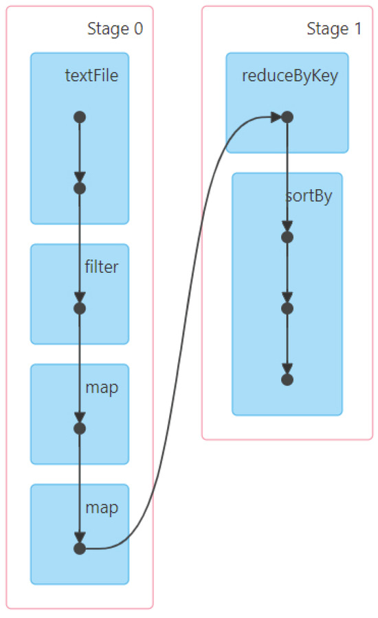
Figure 5.
DAG of TopN application.
Based on the steps described in Section 3, we extract the name of the operation and nodes from each blue rectangle in each stage. Then, we extract the location of each RDD operation in the code file to facilitate the extraction of anonymous function in each RDD operation. Next, we process the execution order of RDD operations within each stage. The formalizations of RDD operations within and are as follows:
After processing the formalizations of RDD operations within stages, we begin to process the execution relationship between stages. We extract the start and end nodes of the connecting arrows between stages and then obtain the formalization between and based on the node relationship in stage_stage. The formalization between stages is shown below:
Once we obtain the formalization between RDD operations within stages and between stages, we formalize the entire application using Algorithm 4 to replace function names and Algorithm 5 to add action operations that are not displayed in the DAG. The formalized result is shown in Figure 6.
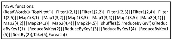
Figure 6.
The formalized result.
The parallelism depends on the default configuration of the Spark framework. In our simulated environment, the number of cores is set to five. Therefore, we configure the parallelism of the functions Filter, Map1, Map2 and ReduceByKey1 to be 5, meaning that each of them can process five data pieces in parallel. Map1 and Map2 distinguish between two different execution logics. For instance, Map1 is used to process (_*2), while Map2 is used to process (_2). Since the take and foreach operations are not displayed in the DAG, they are handled specifically through Algorithm 5 and added to the translated MSVL program.
6. Technical Discussion
MSVL is a framework temporal logic language, constituting an executable subset of PTL. Programs written in MSVL can be utilized for modeling, simulation, and property verification. PPTL, the propositional part of PTL, is capable of expressing fully regular properties, demonstrating greater expressive power than LTL and CTL. The code-level runtime verification tool UMC4M is employed to verify systems written in MSVL and to perform verification based on properties described in PPTL. Due to the unified framework logic of MSVL and PPTL, property verification significantly reduces time overhead.
In previous research on the validation of Spark programs, there has been a greater emphasis on the correctness verification of Spark programs with limited attention given to the verification of their temporal properties. To employ UMC4M for formal verification of Spark programs, particularly focusing on verifying the temporal properties of Spark programs, the key lies in the conversion of Spark programs into MSVL programs. This paper, based on the DAG of Spark programs, transforms them into MSVL programs, presenting a novel approach for the verification of temporal properties in Spark programs.
7. Conclusions
Spark, as a pivotal technology in big data processing, necessitates the validation of its temporal properties. To facilitate the verification of the temporal characteristics of Spark programs using the runtime verification tool UMC4M, the formal modeling of Spark programs through MSVL programs becomes imperative. In this paper, we present a translator, S2M, designed to convert Spark programs into MSVL programs. Consequently, by translating Spark programs into MSVL programs, existing tools can be employed to validate the temporal properties of Spark programs. This transformation effectively shifts the problem of checking the satisfiability of a Spark program to the problem of checking the satisfiability of an MSVL program. However, our current implementation addresses the fundamental transformation from Spark programs to MSVL programs. Further research is required to handle intricate transformations. In the future, we plan to refine the S2M tool for implementing complex transformations and validating the temporal properties of Spark programs using the verification tool UMC4M.
Author Contributions
Conceptualization, K.F. and M.W.; methodology, K.F.; software, K.F.; validation, K.F. and M.W.; investigation, K.F.; resources, K.F.; writing—original draft preparation, K.F.; writing—review and editing, M.W.; supervision, M.W. All authors have read and agreed to the published version of the manuscript.
Funding
This research was funded by Hebei Natural Science Foundation under grant No. F2020201018, Science and Technology Research Project of Higher Education in Hebei Province under grant No. QN2021020 and Advanced Talents Incubation Program of the Hebei University under grant No. 521000981346.
Data Availability Statement
The data presented in this study are available in this article.
Conflicts of Interest
The authors declare no conflict of interest.
Abbreviations
The list of abbreviations and symbols is shown below.
| Symbols | Definition |
| c | Constant |
| x | Variable |
| e | Arithmetic expressions |
| The previous state of variable e | |
| The next state of variable e | |
| The call of the state function g | |
| The call to an external function | |
| b | Boolean expression |
| Positive immediate assignment | |
| Next-state assignment | |
| Conjunction | |
| One unit of time over an interval | |
| ; | Sequential execution |
| Parallel execution | |
| Execution upon satisfaction of boolean expression b | |
| N | Constant |
| M | Constant |
| L | Constant |
| Constant | |
| Global variable | |
| Acronyms | Full Form |
| MSVL | Modeling, Simulation and Verification Language |
| PPTL | Propositional Projection Temporal Logic |
| RDD | Resilient Distributed Datasets |
| DAG | Directed Acyclic Graph |
| PTL | Projection Temporal Logic |
| CTL | Computing Tree Logic |
| LTL | Linear-time Temporal Logic |
References
- Ketu, S.; Mishra, P.K.; Agarwal, S. Performance analysis of distributed computing frameworks for big data analytics: Hadoop vs. spark. Comput. Sist. 2020, 24, 669–686. [Google Scholar] [CrossRef]
- Zhang, J.; Lin, M. A comprehensive bibliometric analysis of Apache Hadoop from 2008 to 2020. Int. J. Intell. Comput. Cybern. 2023, 16, 99–120. [Google Scholar] [CrossRef]
- Zaharia, M.; Xin, R.S.; Wendell, P.; Das, T.; Armbrust, M.; Dave, A.; Meng, X.; Rosen, J.; Venkataraman, S.; Franklin, M.J.; et al. Apache spark: A unified engine for big data processing. Commun. ACM 2016, 59, 56–65. [Google Scholar] [CrossRef]
- Chambers, B.; Zaharia, M. Spark: The Definitive Guide: Big Data Processing MADE Simple; O’Reilly Media: Sebastopol, CA, USA, 2018. [Google Scholar]
- Kalia, K.; Gupta, N. Analysis of hadoop MapReduce scheduling in heterogeneous environment. Ain Shams Eng. J. 2021, 12, 1101–1110. [Google Scholar] [CrossRef]
- Hedayati, S.; Maleki, N.; Olsson, T.; Ahlgren, F.; Seyednezhad, M.; Berahmand, K. MapReduce scheduling algorithms in Hadoop: A systematic study. J. Cloud Comput. 2023, 12, 143. [Google Scholar] [CrossRef]
- Ghazi, M.R.; Gangodkar, D. Hadoop, MapReduce and HDFS: A developers perspective. Procedia Comput. Sci. 2015, 48, 45–50. [Google Scholar] [CrossRef]
- Liu, J.; Li, J.; Li, W.; Wu, J. Rethinking big data: A review on the data quality and usage issues. Isprs J. Photogramm. Remote. Sens. 2016, 115, 134–142. [Google Scholar] [CrossRef]
- Wang, M.; Tian, C.; Duan, Z. Full regular temporal property verification as dynamic program execution. In Proceedings of the 2017 IEEE/ACM 39th International Conference on Software Engineering Companion (ICSE-C), Buenos Aires, Argentina, 20–28 May 2017; pp. 226–228. [Google Scholar]
- Wang, M.; Tian, C.; Zhang, N.; Duan, Z. Verifying full regular temporal properties of programs via dynamic program execution. IEEE Trans. Reliab. 2018, 68, 1101–1116. [Google Scholar] [CrossRef]
- Duan, Z. An Extended Interval Temporal Logic and a Framing Technique for Temporal Logic Programming. Ph.D. Thesis, Newcastle University, Newcastle, UK, 1996. [Google Scholar]
- Duan, Z. Temporal Logic and Temporal Logic Programming; Science Press: Sydney, Australia, 2005. [Google Scholar]
- Yang, K.; Duan, Z.; Tian, C.; Zhang, N. A compiler for MSVL and its applications. Theor. Comput. Sci. 2018, 749, 2–16. [Google Scholar] [CrossRef]
- Zhang, N.; Duan, Z.; Tian, C. A mechanism of function calls in MSVL. Theor. Comput. Sci. 2016, 654, 11–25. [Google Scholar] [CrossRef]
- Duan, Z.; Tian, C.; Zhang, L. A decision procedure for propositional projection temporal logic with infinite models. Acta Inform. 2008, 45, 43–78. [Google Scholar] [CrossRef]
- Duan, Z.; Tian, C. A practical decision procedure for propositional projection temporal logic with infinite models. Theor. Comput. Sci. 2014, 554, 169–190. [Google Scholar] [CrossRef]
- Yang, X.; Wang, X. A Practical Method based on MSVL for Verification of Social Network. In Proceedings of the 2021 8th International Conference on Dependable Systems and Their Applications (DSA), Yinchuan, China, 5–6 August 2021; pp. 383–389. [Google Scholar]
- Zhao, L.; Wu, L.; Gao, Y.; Wang, X.; Yu, B. Formal Modeling and Verification of Convolutional Neural Networks based on MSVL. In Proceedings of the 2022 9th International Conference on Dependable Systems and Their Applications (DSA), Wulumuqi, China, 4–5 August 2022; pp. 280–289. [Google Scholar]
- Wang, M.; Li, S. Formalizing Spark Applications with MSVL. In Proceedings of the International Workshop on Structured Object-Oriented Formal Language and Method, Singapore, 1 March 2021; Springer: Cham, Switzerland, 2020; pp. 193–204. [Google Scholar]
- Luo, N.; Yu, Z.; Bei, Z.; Xu, C.; Jiang, C.; Lin, L. Performance modeling for spark using svm. In Proceedings of the 2016 7th International Conference on Cloud Computing and Big Data (CCBD), Macau, China, 16–18 November 2016; pp. 127–131. [Google Scholar]
- Grossman, S.; Cohen, S.; Itzhaky, S.; Rinetzky, N.; Sagiv, M. Verifying equivalence of spark programs. In Proceedings of the Computer Aided Verification: 29th International Conference, CAV 2017, Heidelberg, Germany, 24–28 July 2017; Part II 30. Springer: Berlin/Heidelberg, Germany; 2017; pp. 282–300. [Google Scholar]
- Beckert, B.; Bingmann, T.; Kiefer, M.; Sanders, P.; Ulbrich, M.; Weigl, A. Relational equivalence proofs between imperative and MapReduce algorithms. In Proceedings of the Verified Software. Theories, Tools, and Experiments: 10th International Conference, VSTTE 2018, Oxford, UK, 18–19 July 2018; Revised Selected Papers 10. Springer: Berlin/Heidelberg, Germany, 2018; pp. 248–266. [Google Scholar]
- Yin, J.; Zhu, H.; Fei, Y.; Fang, Y. Modeling and Verifying Spark on YARN Using Process Algebra. In Proceedings of the 2019 IEEE 19th International Symposium on High Assurance Systems Engineering (HASE), Hangzhou, China, 3–5 January 2019; pp. 208–215. [Google Scholar]
- Baresi, L.; Bersani, M.M.; Marconi, F.; Quattrocchi, G.; Rossi, M. Using formal verification to evaluate the execution time of Spark applications. Form. Asp. Comput. 2020, 32, 33–70. [Google Scholar] [CrossRef]
- de Souza Neto, J.B.; Martins Moreira, A.; Vargas-Solar, G.; Musicante, M.A. TRANSMUT-Spark: Transformation mutation for Apache Spark. Softw. Testing, Verif. Reliab. 2022, 32, e1809. [Google Scholar] [CrossRef]
- Dietsch, D.; Heizmann, M.; Langenfeld, V.; Podelski, A. Fairness modulo theory: A new approach to LTL software model checking. In Proceedings of the Computer Aided Verification: 27th International Conference, CAV 2015, San Francisco, CA, USA, 18–24 July 2015; Proceedings Part I 27. Springer: Berlin/Heidelberg, Germany, 2015; pp. 49–66. [Google Scholar]
- Brockschmidt, M.; Cook, B.; Ishtiaq, S.; Khlaaf, H.; Piterman, N. T2: Temporal property verification. In Proceedings of the Tools and Algorithms for the Construction and Analysis of Systems: 22nd International Conference, TACAS 2016, Held as Part of the European Joint Conferences on Theory and Practice of Software, ETAPS 2016, Eindhoven, The Netherlands, 2–8 April 2016; Proceedings 22. Springer: Berlin/Heidelberg, Germany, 2016; pp. 387–393. [Google Scholar]
- Cook, B.; Khlaaf, H.; Piterman, N. On automation of CTL* verification for infinite-state systems. In Proceedings of the International Conference on Computer Aided Verification, San Francisco, CA, USA, 18–24 July 2015; Springer: Berlin/Heidelberg, Germany, 2015; pp. 13–29. [Google Scholar]
- Cook, B.; Koskinen, E. Making prophecies with decision predicates. In Proceedings of the 38th Annual ACM SIGPLAN-SIGACT Symposium on Principles of Programming Languages, Austin, TX, USA, 26–28 January 2011; pp. 399–410. [Google Scholar]
- Duan, Z.; Yang, X.; Koutny, M. Framed temporal logic programming. Sci. Comput. Program. 2008, 70, 31–61. [Google Scholar] [CrossRef]
- Wang, X.; Tian, C.; Duan, Z.; Zhao, L. MSVL: A typed language for temporal logic programming. Front. Comput. Sci. 2017, 11, 762–785. [Google Scholar] [CrossRef]
Disclaimer/Publisher’s Note: The statements, opinions and data contained in all publications are solely those of the individual author(s) and contributor(s) and not of MDPI and/or the editor(s). MDPI and/or the editor(s) disclaim responsibility for any injury to people or property resulting from any ideas, methods, instructions or products referred to in the content. |
© 2023 by the authors. Licensee MDPI, Basel, Switzerland. This article is an open access article distributed under the terms and conditions of the Creative Commons Attribution (CC BY) license (https://creativecommons.org/licenses/by/4.0/).