Article

The Role of Physical Layer Security in IoT: A Novel Perspective

Università di Firenze, Department of Information Engineering, Via di Santa Marta 3, 50139 Firenze, Italy
*
Author to whom correspondence should be addressed.
Information 2016, 7(3), 49; https://doi.org/10.3390/info7030049
Submission received: 16 June 2016 / Revised: 22 July 2016 / Accepted: 27 July 2016 / Published: 2 August 2016
(This article belongs to the Special Issue Physical Layer Security in Wireless Networks)

Abstract

:
This paper deals with the problem of securing the configuration phase of an Internet of Things (IoT) system. The main drawbacks of current approaches are the focus on specific techniques and methods, and the lack of a cross layer vision of the problem. In a smart environment, each IoT device has limited resources and is often battery operated with limited capabilities (e.g., no keyboard). As a consequence, network security must be carefully analyzed in order to prevent security and privacy issues. In this paper, we will analyze the IoT threats, we will propose a security framework for the device initialization and we will show how physical layer security can effectively boost the security of IoT systems.

1. Introduction

With the ever increasing use of the Internet of Things (IoT) paradigm, Wireless Sensor Networks (WSNs), Wireless Sensor and Actuator Networks (WSAN), Body Area Network (BANs), and other kinds of small devices are becoming part of a connected environment, whose overall goal is to enhance our life quality. The possible use-cases span from smart buildings to workplaces and medical centers.
Spacing from small data collection sensors to actuators for door opening and even safety applications, IoT uses IPv6 protocol as a building block to enable device-to-device and device-to-human communications. The pervasive spread of sensors constitutes a valid help to the users’ life, and the Machine-to-Machine (M2M) applications enable effective and powerful intelligent environments. However, if not properly secured, the communications between these devices pose security or safety risks.
IoT devices have strong restrictions in terms of computation capabilities, a widespread distribution, and they are connected to the internet. As a consequence, they make up a whole new class of things that could be attacked by spiteful people. From one side, the IoT suffers from the kind of attacks of the legacy connected devices, i.e., computers, Local Area Networks (LANs), etc. From the other side, it has to cope with new kinds of weaknesses, i.e., privacy related ones. There are some aspects of the latter ones that can be used by an attacker to trace the user behavior and undermine the user’s privacy. This paper focuses on these problems and provides a novel approach to enhance the data security and privacy by using classical cryptography along with state-of-the-art physical network security.
The standards provide some cryptographic methods to protect the IoT traffic, but cryptography is only a technique. Securing a system means understanding and preventing the possible threats without hindering the users’ experience and the system usability. Moreover, the limited devices resources often require some tradeoffs, which must be considered when studying system security.
As an example, the IEEE 802.15.4 standard [1] foresees ciphering the payload, but the headers containing layer 2 addresses the source and destination of the packets are not encrypted. An eavesdropper can collect this information without having to decrypt the packets. Moreover, the standard does not fully describe many security-related mechanisms, as we will outline in the following. This can severely hinder any effort in securing the network.
In order to effectively provide a comprehensive security and privacy solution, it is necessary to analyze the scenario and its threats. Although similar, a smart building is different from a smart work environment. The solutions, especially the ones involving classical cryptography and physical layer security, must be tailored for the specific threats. The goal is to provide a cost-effective solution, while also taking into account the energy requirement of the various solutions (many devices can be battery-operated).
This paper is structured as follows. In Section 2, we will present other works about privacy and security in IoT systems, in Section 3, we will describe our reference scenario and perform its threat analysis. In Section 4, our method for achieving better privacy is proposed, and, in Section 5, the security achievements will be evaluated. The implementation efforts are briefly described in Section 6, while conclusions are drawn in Section 7.

2. State-of-the-Art

The usual method to enforce the security requirements of a system is to resort to cryptographic methods. These techniques aim at obfuscating the information in the transmission, making the receiver unable to infer the content of a received message, unless resorting to very high computational power. Information obfuscation is usually performed at layer 2 or above.
Other methods try to hide the transmission at the physical layer. This was historically achieved with particular techniques that spread the signal under the noise threshold of the illicit receiver. However, recently, physical layer security scope has been extended to also include more interesting properties. We will now briefly outline the most relevant elements for our research.

2.1. Classic Security

The security of IoT systems is very fragmented. Without lack of generality, we will refer in the following to the IEEE 802.15.4 standard [1]. Other systems have different, although similar, cryptographic methods.
The standard states that there are seven (+1) possible ciphering mechanisms: no security (the +1), encryption with AES-CTR (Advanced Encryption Standard - Counter), authentication with AES-CBC (Cipher Block Chaining)-MAC (three Message Authentication Code (MAC) lengths, 32/64/128 bits), and authentication + encryption with AES-CCM (Counter with CBC-MAC), three MAC lengths, as before. For further details, the reader can refer to [1,2].
The underlying algorithm, AES, is widely proven to be secure and robust. The issue is in the key management. Usually, this task is left to the upper layers that are in charge to set the correct parameters for the MAC layer cryptography.
The standard does not propose any key management schemes. The most common solution is to use a Pre-Shared Key (PSK), installed a priori in the nodes. This approach is not scalable: adding and removing devices from the network requires (usually) to update the firmware in all the devices in order to change the keys. Moreover, an attacker can steal a device and acquire the key by physically accessing a device.
Another option is to use a configuration system to install the keys during the device bootstrap. However, since the communications in this phase are not protected, it is possible that an attacker could eavesdrop the keys.
Many other works have been proposed that address the key management using Elliptic Curve 79 Cryptography (ECC) as in [3,4] and related works. Recently, the evolution of the hardware characteristics of the sensors and the optimization of the ECC algorithms, including the hardware acceleration in chipset such as the Texas Instruments CC2538, has made possible to use this technology into the IoT devices.
The actual deployment of ECC systems is controversial due to the high consumptions of both energy and memory, and the cost and complexity to maintain the certification authority infrastructure. However, the ECC allows a more fine grained authentication of the sensors and the possibility to generate dynamic keys to be used in AES. Indeed, we will use this cryptographic system as described further in the paper.

2.2. Physical-Layer Security

Security at the physical layer was mainly intended in the past as the use of a spread spectrum technique (frequency hopping, direct sequence coding, etc.) in order to avoid eavesdropping. These physical layer techniques aimed at hiding the mere existence of a node or the fact that communication was even taking place. The main issue is that once the adversary knows the details of the communication system, the whole security is undermined. As a matter of fact, spread spectrum techniques are not considered anymore as security systems but rather as fading countermeasures.
It is well known that classical encryption techniques have only unproven complexity-based secrecy [5]. We also know that strong information-theoretic secrecy or perfect secrecy is achievable by quantum cryptography based on some special quantum effects such as intrusion detection and impossibility of signal clone [6]. Unfortunately, the dependence on such effects results in extremely low transmission efficiency because weak signals have to be used. In addition, other limitations such as change in polarization, lack of digital signatures, need of a dedicated channel, short distance and tolerable errors make these techniques not yet efficiently implementable [7].
One of the recent attempts to specify secret channel capacity is [8], where the MIMO (multiple input multiple output) secret channel capacity is analyzed under the assumption that the adversary does not know even his own channel. However, such techniques are not simple, due to the fact that they need a high number of antennas on both sides of the radio link to operate.
Existing physical layer security approaches can be classified based on the physical characteristic that is exploited:
  • Secrecy Capacity: the maximum rate achievable between the legitimate transmitter–receiver pair subject to the constraints on information attainable by the unauthorized receiver, i.e., the maximum transmission rate at which the eavesdropper is unable to decode corresponds to the difference between the capacity of the legitimate link and the eavesdropper link.
  • Channel Signature/Fingerprint: security based on the exploitation of one of the channel characteristics. Radio Frequency (RF) characteristics of the legitimate link, e.g., the channel impulse response, are used to produce a shared secret. Use of multiple directional antennas to randomize the transmitted information stream or to inject noise in the direction of the eavesdropper.
  • Spectrum Spreading of Signal Energy: use of a Spread Spectrum (SS) techniques like Direct Sequence Spread Spectrum (DSSS) and Frequency Hopping Spread Spectrum (FHSS).
  • Cooperation: friendly nodes send noisy signals towards the eavesdropper in order to deteriorate its link.
Recently, other techniques that use the channel reciprocity to produce a secret appeared. In [9,10], the fading experienced by the channel between the two legitimate users is used to create a secret dynamically (technically, this technique is not at the physical layer but at the link layer). In [11], artificial noise is used to produce secrecy given a specific zone where security must be assured. In [12,13,14], noise is used as the carrier of the information in a closed-loop scheme. Other recent works [15,16] make use of the cooperation of surrounding friendly nodes to produce a secrecy rate in a transmission link between two nodes in the network. The friendly nodes mainly soil the channel of the adversary nodes. In [17], nodes equipped with multiple antennas use the same logic: they transmit artificial noise selectively in the direction of the adversary, limiting it in the direction of the friend/desired user. Game theory can be used to study the optimization of reliability vs. secrecy for both legitimate nodes and eavesdroppers [18]. A review of cooperative techniques for enhancing the security can be found in [19].
Many of the approaches described above are based on assumptions that make them not easily implementable in a real world: some of those require that a common a priori secret is shared by the legitimate users or exchanged in the start-up phase through insecure channels, and some others assume to know that an eavesdropper is present and where it is located. As a matter of fact, almost all existing results on secret channel capacity are based on some kinds of assumptions that appear impractical [20,21]. It has been a challenge in information theory for decades to find practical ways to realize information-theoretic secrecy.
Perfect secrecy is achievable by using physical layer techniques subject to the condition that the channels are unknown to unauthorized users or the channel of the unauthorized users is more noisy than that of the authorized users. While the traditional encryption techniques rely heavily on the upper-layer operations, it is interesting to know whether the physical layer can have some built-in security to assist the upper-layer security designs. Instead of using an additional channel, the physical layer methods can also be employed to distribute secret keys, to supply location privacy and to supplement upper-layer security algorithms. The application of physical layer security schemes makes it more difficult for attackers to decipher the transmitted information.
In physical layer security for wireless networks, the secrecy rate is defined as the rate at which information can be transmitted secretly from a source to its intended destination. The maximum achievable secrecy rate is named the secrecy capacity. For example, in a Gaussian channel, the secrecy capacity is defined as the difference of the (Shannon) capacity of the channel between the source and the destination and the capacity of the channel between the source and an eavesdropper [5,22]. The secrecy is defined as information-theoretic secrecy, i.e., the adversary’s received signal gives no more information for eavesdropping than purely guessing.
The implementation of this kind of physical layer security techniques, namely the information-theoretical secrecy, is not straightforward nor trivial. First proposals deal with the exploitation of the wireless channel between legitimate users in order to extract a key to be used for encrypting the message [23]. The information-theoretical secrecy ensures that if the extraction is made under the assumption to have an advantage over Eve’s channel, the key is not recoverable by Eve in any way. An exhaustive review of cross-layer techniques for enhancing the security can be found in [23]. In [24], the security issues and solutions are reviewed for what concerns the IoT topic area. The physical-layer security anyway is not taken into account as information-theoretical secrecy. An overview of the challenges facing physical-layer security is reported in [25].
This paper does not deal with key extraction, but the direct use of the results of information-theoretical secrecy to produce a secure link, i.e., under which conditions in practical applications, such as IoT applications, the information-theoretical secrecy can be directly applied, so that the eavesdropper can not recover any information about the message by observing the channel.

3. Scenario and Threat Analysis

As we outlined in the Introduction, the IoT paradigm is used in a wide range of applications and scenarios, ranging from professional (e.g., BAN for e-Health) to recreational (e.g., WSN for sport players tracking). These applications are very different, and each one has its own requirements in terms of data confidentiality, data integrity, etc. Despite the differences, about all the devices used in IoT share some common design features: they are small, battery-operated, and lack a proper input system.
The above-mentioned limitations, along with the need to keep the single device cost low, raise a number of problems in securing the system. Assuming that the data channel could be made secure by a proper cryptographic scheme (and also this assumption is not to be taken for granted), there are two major points where IoT devices are subject to attacks that are substantially different from the normal threats to other networked devices.
The first weakness of IoT devices comes from their configuration (see [26,27]). Devices have a lifecycle (manufacturing, deployment, maintenance, retirement). During each step, it is possible that the user needs to reconfigure some of the device security properties (e.g., device network association, keys, etc.). This reconfiguration process is, of course, an extremely delicate procedure. It must be performed on a secure channel, or an attacker could acquire priority class information.
The second weakness arises from the lack of a well-defined network topology. Most IoT systems are mesh, ad hoc, multi-hop networks. This has the huge benefit of increasing the system resiliency and network lifetime, but it also enables a number of attacks especially targeted to the routing and multi-hop schemes. These attacks are well-known in literature, and it is possible to apply some countermeasures. Nevertheless, detecting and blocking the attacks is still an open issue. The detection is complex, as the global network knowledge is not possible, and the blocking is difficult as well. As a matter of fact, distributed firewalls could be technically feasible, but they would consume precious resources in the devices.
Data encryption can enhance the network security and privacy. However, key management is always an open issue [28]. It must be stressed that key agreement (or key dissemination) is a common problem to all the network layers, from MAC to IP to Application.
Finally, as we mentioned before, the MAC headers are usually not encrypted, allowing attacks to the user’s privacy thanks to correlation attacks.

3.1. Scenario

In order to evaluate the IoT threats and possible countermeasures, we will focus on the professional environment, and, in particular, on e-Health applications.
One of the most promising use-cases of BANs is their application to rehabilitation and continuous patient condition monitoring. Without loss of generality, we will focus on the following use-case: a patient enters a rehabilitation room, where a doctor places some health monitoring devices. During the rehabilitation session, the sensors gather some data and transmit them to a monitor station through a gateway. When the session ends, the doctor removes the sensors from the patient.
The doctor must be able to “install” a device (i.e., activate it on a particular patient) and “decommission” the device (i.e., remove it from the patient). These operations must be secure, fast, and foolproof.
In order to preserve the patient’s privacy, his/her personal data must be encrypted. Moreover, only the professional responsible for the device management (doctor, nurse, etc.) must be able to manage the devices, and he/she must be identifiable by the system, in order to prevent mistakes.
As mentioned before, these requirements could be fulfilled by using appropriate cryptographic schemes. The problem is how to manage the cryptographic material. The solution can be to renew all the cryptographic keys each time a doctor has to use the devices. However, this should be an easy to perform and secure procedure, able to be performed also by unskilled personnel.
Another scenario could be one of goods tracking and delivery: a shipment could be equipped with a tracking sensor (possibly measuring also other data, like vibrations, temperature, etc.). The shipping personnel should be able to access a group of devices to read and/or store data (e.g., the arrival time to a location), possibly with different access rights to the stored data according to the role in the organization (simple driver, manager, etc.).

3.2. Attacker Capabilities

We assume that the attacker is an eavesdropper, i.e., it is interested in acquiring sensitive information by means of passive attacks. In a passive attack, the threat agent does not modify or interfere with the normal communications between the legitimate users. In this way, the attack can go unnoticed for a long time.
Moreover, we assume that the attacker knows everything about the system under attack, and, in particular, its modulation and coding schemes, the used protocols, the channels, etc. This is consistent with the Kerckhoffs’ principle (or the equivalent Shannon’s maxim) stating that the enemy knows the system, and that security is not to be reached by obscurity.
Finally, we limit the attacker’s hardware and software capabilities to the best off-the-shelf hardware and software available.

3.3. Threat Analysis

Usually, the threat analysis is based on the network levels, i.e., MAC/PHY (Physical Layer), Data link, etc., or the attack types. On the contrary, we want to highlight how different device lifetime events can be used by an attacker.

3.3.1. Device Manufacturing

An attack performed during the device manufacturing can install a backdoor or weaken a cryptographic library, enabling the attacker to perform various illicit actions. In this category, we also classify the problems arising from bad device manufacturing, e.g., zero-day bugs, buffer overflows, bad use of libraries, etc. The above threats should be mitigated by an appropriate device manufacturing cycle, including a mandatory Vulnerability Assessment (VA) process for devices carrying sensitive data.

3.3.2. Device Deployment

Device deployment is usually performed by certified technicians. As a consequence, it should not represent a security issue. Nevertheless, some aspects of device management may have to be left to the users. In this case, the system security could be undermined. As an example, a network could rely on the user identity to configure the access grants to some services, and the user identity is verified through an ID card. The system is perfectly safe, assuming that all the users keep their cards private and secured, which may not be always the case.

3.3.3. Device Maintenance

We name the device maintenance just for completeness. All the operations belonging to maintenance (i.e., device firmware upgrade, device substitutions, etc.) should be performed by certified technicians. However, the actual trend is to allow Over The Air (OTA) system upgrades and configuration setup. While this is a very handy feature, it also allows an attacker to take the complete control of a system just by mimicking the upgrade process. It would seem logical that OTA and remote management capabilities should be extremely robust against possible attacks. Sadly, this is not the case. Backdoors have been found in many IoT and commercial internet devices (e.g., home routers), and, in many cases, they had just been ’forgotten’ by the developers.

3.3.4. Device Operations

A number of attacks can be performed during the normal device operations. Typically, they can be classified according to the attacked layer:
  • Physical (L1), e.g., jamming.
  • MAC (L2), e.g., MAC spoofing, etc.
  • Network (L3), e.g., routing attacks, IP spoofing, etc.
  • Upper layers, e.g., man in the middle, etc.
Despite the variety of attacks, a strong enough encryption system can protect the network from the majority of them. However, it must be noted that the encryption of the payload does not protect the headers, e.g., a MAC-level encryption will not encrypt the MAC headers. As a consequence, it is always convenient to move the encryption to the lowest possible layer, in order to prevent attacks based on the observed user’s behavior.
Cryptographic techniques have a computational cost: the harder a scheme is, the more computationally heavy is. Contrary to information-theoretical approaches, cryptography reaches its security by making it unfeasible for the attacker to decrypt a message. This is achieved by balancing the cryptography robustness and the key validity time. As a consequence, keys must be changed as often as possible. However, this is not a simple task in the case of IoT devices.

3.3.5. Device Retirement

Device decommissioning should not represent a security threat, apparently. Indeed, it can be a serious problem if devices are not properly erased. Depending on the cryptographic schemes, a used device could keep relevant data in its memory . In particular, the memory could contain some patient data and some cryptographic keys used by the network. This problem is not limited to normal device decommissioning (e.g., obsolescence, faults, etc.): it applies also to lost devices, i.e., stolen or not found anymore.

3.3.6. Eavesdropping Effects on the System

As stated previously, we will focus our attention on preventing an eavesdropper. As a matter of fact, we assume that the whole system is using cryptographic techniques, and the only weak element is the configuration phase, where keys are negotiated between the devices.
If an attacker is able to successfully decode all the configuration messages, it could (given enough computational power) decrypt the following messages. As a consequence, the attacker could use passive (offline) attacks to recover sensitive data or active (online) attacks, for example, to modify device firmware by installing malicious software.
We will focus our attention on the eavesdropping of the configuration phase because we believe that this is the most important part to secure.
We will not focus in the present paper on the effects of other attack types that can be carried out by a passive eavesdropper, like data correlation. For a discussion of possible privacy enhancement methods, the reader can refer to [29].

4. Proposed Framework

As outlined in the previous sections, the most critical elements are the initial configuration and devices that are stolen and/or compromised. The solution to the first issue is the focus of the present work. The second issue must be addressed through a combination of management procedures (e.g., to track lost devices) and protocols (e.g., key renew, internal memory reset, etc.).
As stated in Section 3.1, we want to configure a device’s cryptographic keys in a secure and error proof way. This can be accomplished by using a master configurator. This device (similar to One Time Password (OTP) devices that are used in online banking) has to provide secure, fresh keys to the devices requesting them.
In our selected scenario, the configurator should be a small form factor device that the doctor keeps in his pocket, e.g., a credit card or a key chain. Furthermore, it has not to be connected to any network. It must operate as a stand alone module, whose only goal is to generate a key and to securely transmit to the intended device.
Our idea is that the configurator generates and signs ECC certificates. When the doctor has to configure some devices, for example a group of BAN sensors, he activates his configurator, gets in range of the device to configure, and presses a button (or similar input) on the configurator in order to transfer the generated certificates to the device.
The system configuration is performed in three steps: (1) the creation of a secure channel; (2) the creation and transmission of the keys; and (3) the switch to a secure higher-bandwidth protocol.
Many methods could be used to create a secure channel. However, we can not rely on cryptography due to the lack (in this phase) of a shared secret or inherently secure channels (e.g., a cable) because they are impractical. As discussed in Section 2, the physical layer techniques can provide some useful approaches to solve the dilemma. Some further requirements are that the system should not require complex hardware (i.e., keep the form factor as small as possible), and that the energy consumption should be as small as possible (i.e., have a long device lifetime). In order to meet these requirements, we chose to use the property of secret capacity and transmission rate (specifically, the security over reliability condition). We define a boundary for the coding ratio and the context (i.e., distance of the parties) in order to allow the communication of the two legitimate entities, while not disclosing any information to the attacker. The actual coding scheme depends to the specific technology used and will not be analyzed because we want to remain as general as possible.
After creating a secure communication channel, the configurator generates two asymmetric key pairs and signs them with its own Certification Authority (CA). This CA signature identifies the configurator and, as a consequence, the doctor. The association between keys, CA and patient information is administratively made in an anonymous way to preserve the patient privacy. It is sufficient to record only the time, the doctor and the patient. From the signature of the keys, it is possible to match the doctor who installed them.
We use two pairs of keys because one is used to authorize the device toward the network and vice versa, while the other key pair is used in the routing algorithm. It is important that, after use, the installed keys will be deleted from the devices. The gateway must be configured as well because it must have a key pair signed by the doctor CA. This ensures that the devices will only communicate with the authorized gateway. The gateway could be either in the hospital or in the patient house, i.e., for home monitoring, but it has to be properly secured (doctor-installed keys, Virtual Private Network (VPN) for the backhaul, trusted firmware) to preserve the patient privacy. Eventually, other parameters like the channel number, addresses or other parameters can also be sent.
All the above-mentioned parameters and keys are sent over the secure channel. In the last step, the devices and the gateway use the keys and configurations to setup a BAN, e.g., by using IEEE 802.15.4, IEEE 802.15.6 or similar.

Secure Channel Analysis

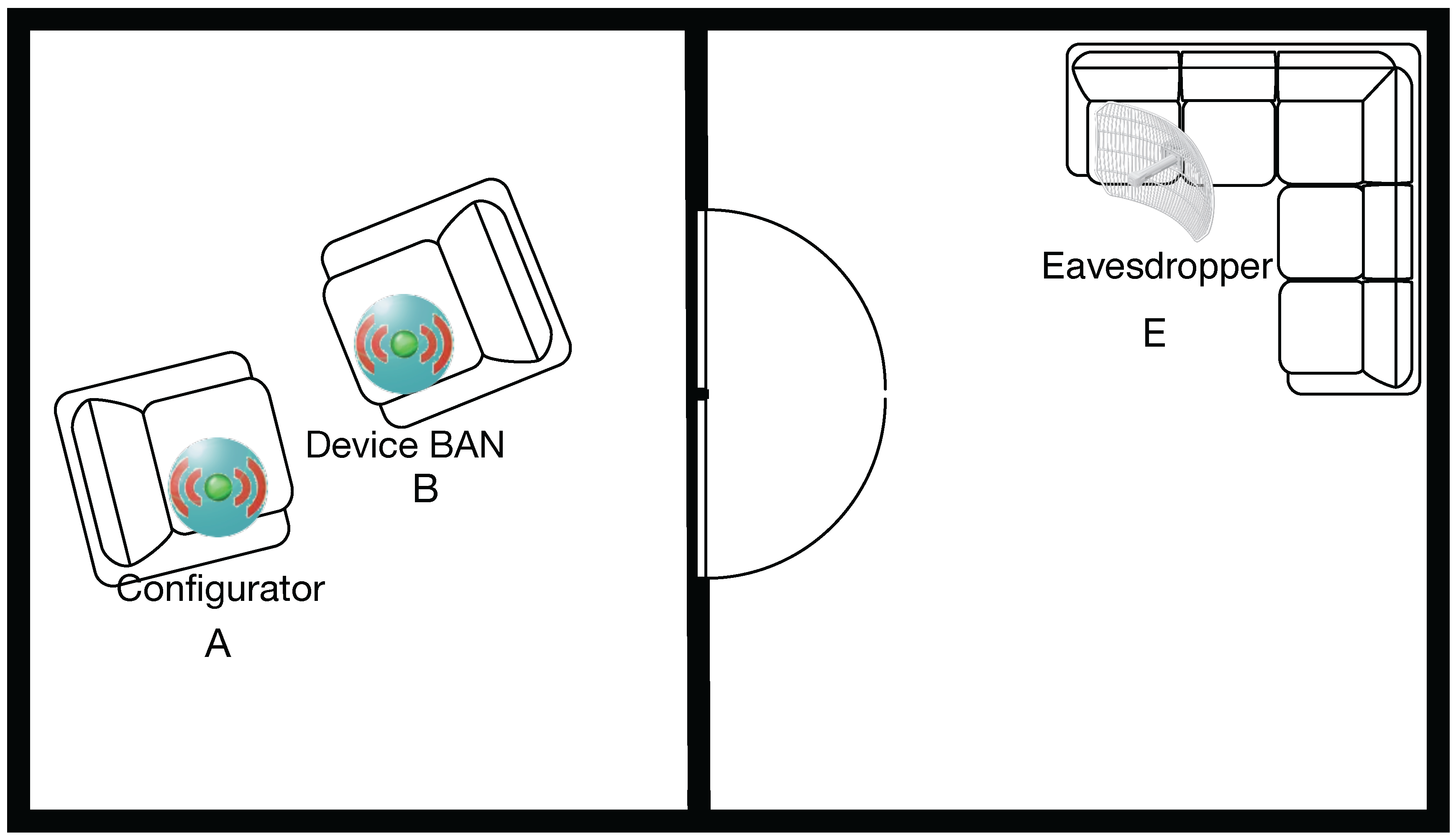
We consider the case where the configurator, A, and the device to be configured, B, want to exchange some secret informations (e.g., cryptographic keys, configuration parameters, etc.). There is also an eavesdropper E that wants to sniff the informations for illicit purposes.
According to [5] (Chapter 5, Remark 5.1), the secrecy capacity C S of a circularly-symmetric Gaussian wiretap channel is the difference between the channel capacity between A and B, C A B , and the one between A and E, C A E :
C S = max 0 , C A B C A E = [ log ( 1 + S N R A B ) log ( 1 + S N R A E ) ] +
The secrecy capacity is the maximum secrecy rate that can be achieved by the legitimate users given the presence/position of an eavesdropper.
In order to obtain a secrecy capacity strictly positive, the quality of the channel between A and B should be better than the channel between A and E. A secure communication is possible if and only if the legitimate receiver has a better Signal to Noise Ratio (SNR) than the eavesdropper. As will be analyzed further in the paper, this means that if the channel capacity (strictly dependent on the SNR) for B is better than the channel capacity of E, it is possible to create a modulation and coding scheme not exposing any information to E because the signal that E can observe from the channel is not enough to recover any information about the message.
In practice, this is likely to happen if the eavesdropper is located farther away from the transmitter than the legitimate receiver and receives attenuated signals. However, also the receiving device quality must be taken into account, as we will see later.
Using this property has some advantages over the other possible physical security methods. It does not require additional hardware, no specific modem, and it can be applied to a variety of existing systems. The main drawback is the low throughput, although this is a common characteristic of the physical layer security techniques, and is the bill to pay for the security of the channel. Due to the low obtainable data rate, this method is employed to send only the keys to be used in the other communication protocols, i.e., IEEE 802.15.4.
In our scenario, the configurator has to send two ECC key pairs to the device, as explained before. In this way, the data to exchange during the setup are relatively low. We assume a maximum of about 2 s for the configuration exchange. Afterwards, the successive communications can be encrypted with the “native” protocol encryption techniques, thus allowing a higher throughput.
From Equation (1), we have that with a rate R that satisfies R < C S , the security over reliability condition, the communication from A to B is secured from an eavesdropper E. Security over reliability means that the rate R must satisfy at the same time the security condition Equation (2) and the quality of service condition, i.e., must be higher than the minimum rate to provide the service. The rate lower bound Equation (3) is given by the amount of information to transmit, about 32 kb, divided by a reasonable amount of time to complete the configuration procedure, about 2 s. This R m i n consists of at least two pairs of ECC public/private keys but can include other configuration parameters as the flag to reset the memory or patient informations. The upper bound is C S , leading to Equation (4):
R < C S
R m i n = 32 kb 2 s 16 kb / s
R m i n < R < C s
The generic channel capacity between two entities x and y is given in Equation (5). C x y is a function of the bandwidth of the signal W and the logarithm of the SNR:
C x y = W log 2 1 + S N R x y = W log 2 1 + P t x · G t x · G r x · λ 2 4 π d x y 2 · W · k · T
The formula expansion is easy to demonstrate, considering that:
S N R x y = P r x x y N
P r x = P t x · G t x · G r x L ( d )
N = W · k · T
L ( d x y ) = 4 π d x y λ 2
In Equations (5)–(9), the noise N is Additive White Gaussian Noise (AWGN) and is a function of the bandwidth W, the Boltzmann constant k and the temperature T. Moreover, we assumed that all the losses due to components other than the transmission and reception (e.g., cables, etc.) are negligible.
The choice of the path loss model has a strong impact on the formula. Without loss of generality, we assume the free space path loss L ( d ) as stated in Equation (9). For this model to hold, the receiver must be in the far field condition. Given the small dimensions of the antenna, the radiation is far field approximately after 2λ from the transmitter, where λ is the wave length. λ is obtained from the central frequency f = c / λ . For a generic 2.4 GHz system, the λ 12.5 cm. This means that the formula of the path loss does not have to take into account the reactive part of the electromagnetic signal irradiated from the antenna, the parts that decrease as d 3 and successive orders (see [30]). It is worth noticing that, for Near Field Communication (NFC), the λ 22 m , thus the far field is ≈ at 44 m.
We want to remark that the results that we obtained can be extended to more complex propagation models and to near field cases.
The actual channel capacity C A B and C A E are represented in Equations (10) and (11), respectively. The differences between these formulas are the antenna gains and the distance of the receiver from the transmitter A. The secret capacity C S is given by Equation (12). The parameters are summarized in Table 1.
C A B = W log 2 1 + P t x · G t x · G r x B · λ 2 4 π d A B 2 · W · k · T
C A E = W log 2 1 + P t x · G t x · G r x E · λ 2 4 π d A E 2 · W · k · T
C S = C A B C A E = W log 2 1 + P t x · G t x · G r x B · λ 2 4 π d A B 2 · W · k · T W log 2 1 + P t x · G t x · G r x E · λ 2 4 π d A E 2 · W · k · T = W log 2 1 + P t x · G t x · G r x B · λ 2 4 π d A B 2 · W · k · T 1 + P t x · G t x · G r x E · λ 2 4 π d A E 2 · W · k · T
As stated in Section 3.2, the attacker knows the communication system used by A and B. In particular, we assume that the frequency, bandwidth, modulation, etc. are known. The two different elements in Equation (12) are the distance d A E and the antenna gain G r x E .
The advantage of B over E is the shorter distance from the transmitter A. However, the attacker can have a better antenna, i.e., the device E could be equipped with a directional antenna, thus having an higher gain with respect to B. As a consequence, even if the attacker is not in close proximity of the system to attack, it can compensate with a better equipment.
The base idea of this paper is to investigate the possibility of practically applying the information-theoretical secrecy technique, which basically comes from a theoretical approach of the information theory topic.
To ensure that Bob’s channel is better than Eve’s one, the most proposed technique in literature is jamming, i.e., injecting noise into the eavesdropper channel. Anyway, these jamming-type techniques are hardly applicable to the real world, because they assume that:
  • there is (for sure) an eavesdropper,
  • its position is known a priori.
There are some jamming techniques that blindly inject noise into the subspace not occupied by the information signal, but this still means more interference for other legitimate nodes and more energy consumption (not for sending information but only for jamming a potential eavesdropper). Furthermore, it is hard to envision that a standardization body (e.g., FCC) will allow jamming the channel, even by legitimate users. There are more limitations to the real-world application of Physical Layer Security. Due to space constraints, we will not discuss further this point. The interested reader can, for example, refer to [25].
The above conditions can not be satisfied in a real system. We propose here a method that given a specific system, in terms of frequency, bandwidth, distance of the legitimate users, etc., gives back the conditions that lead to define a security area. These conditions are the maximum rate of transmission and the minimum distance of Eve to the legitimate parties. In other words, in our approach, we basically use the results of information-theoretical secrecy to derive, in a real practical application, which is the minimum distance that an eavesdropper should stay from legitimate nodes in order to have a minimum secrecy rate. In practice, this results in a warning zone, i.e., the legitimate nodes have to check that an eavesdropper is not present within that minimum distance, if they want to communicate securely with a minimum target rate.

5. Results

In order to evaluate the system secret capacity, we used MATLAB simulations. The simulation parameters are shown in Table 1. In a real use-case, we will not have any information of both the distance and the antenna gain of the attacker; therefore, we fixed the parameter G r x E to a reasonable high value of 10 dB, while G r x B is 1 dB. The 10 dB value corresponds to a good antenna still relatively small to be hidden in some way (e.g., in a suitcase).

5.1. Proposed Framework Results

Equation (12) depends on many parameters, and some of them are unknown as the distance of the eavesdropper d A E and his antenna gain G r x E . As noted before, we fixed G r x E to a value that we consider a good approximation of what could be the real case. The antennas currently available, and with a relatively small form factor, have approximately this value.
We consider a 2.4GHz communication system, which is often used in IoT systems. About the free space loss model, we acknowledge that it is a questionable choice for indoor cases. However, as we will see in the following, the general results hold. As a matter of fact, the important element is to find a minimum distance for which the Equation (4) is satisfied.
Given that the secret capacity can be also expressed in terms of Signal to Noise Ratios (SNRs) of the legitimate user and the eavesdropper, and we are looking for the points where S N R A B > S N R A E , the path loss model will slightly modify the slope of the curves, but it will not subvert the results.
Moreover, in the real environment, the eavesdropper is likely to be in Non Line Of Sight (NLOS) condition, so its SNR will be lower than what we here estimated. As a consequence, by using an optimistic model for the eavesdropper, we find a conservative value that satisfies the secrecy of the communication with an additional margin.
Given the particular scenario, we varied the distances of both B and E, ranging from 1 m to 3 m and from 1 m to 10 m, respectively. We consider that the configurator and the devices to be configured are in the same room, while the attacker is in the next one, with a distance of some meters from the transmitter, as in Figure 1. The secret capacity C S is shown in Figure 2, where the distance d A B is on the x-axis, d A E is on the y-axis and the z-axis represents C S 
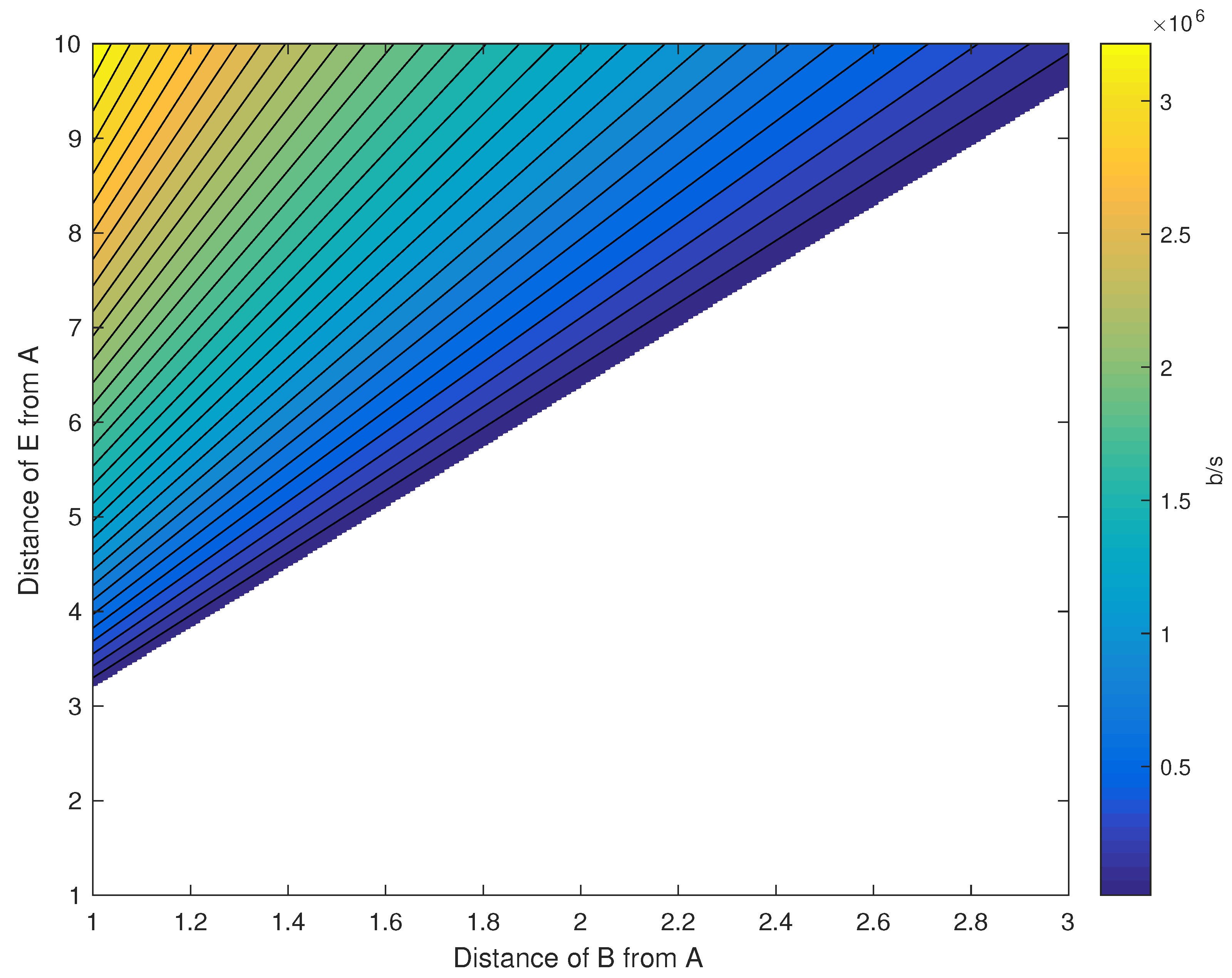
. For the sake of readability, Figure 3 shows the same information in 2D with different colors for different values of C S .
The surface of Figure 2 represents the upper bound of the rate R. The surface is plotted for the values that are bigger than the minimum rate R m i n . In Figure 3, the C S is projected over the 2D plane of the distances d A B and d A E . From the figures, it is clear, for example, that if the distance between the legitimate transmitter (A) and receiver (B) is about 2 m, and they are using the minimum rate, and the eavesdropper should not be closer than about 6 m. A higher rate would require the attacker to be farther away.
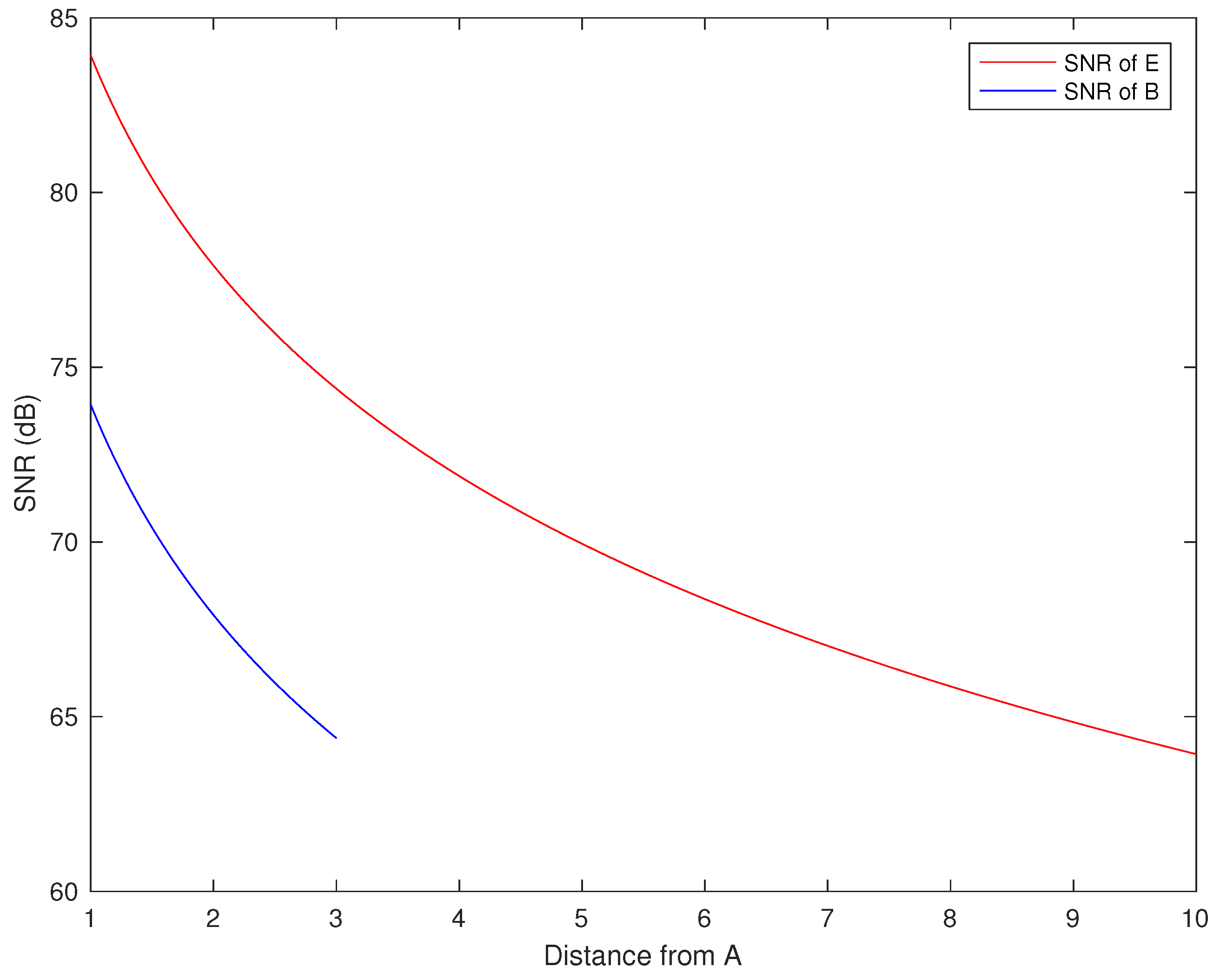
The SNR values for B and E as a function of the distance is shown in Figure 4. Of course, given that the parameters are the same with the exception of the antenna gain, the two curves are shifted by 10 dB.
In order to satisfy the secrecy condition, the SNR of E must be lower than the SNR of B. However, this condition is necessary, but not sufficient. What is evident from this figure is that there is a large region where the secrecy condition is not met by definition, i.e., it is not possible to create a modulation and coding scheme that permits to transmit to B, without E being able to listen to the communication.

5.2. Discussion on the Results

From these results, it is possible to extrapolate two important things. The first is that, for a given distance, d A B there is a minimum distance of E where the minimum rate R m i n can be satisfied and the communication is secure. This implies that A must be sure that E is not close than d A E . For example, with the parameters in Table 1, if B is 2 m from A, then E have to be at least 6.36 m far away to allow a secure transmission using a rate of 16 kb/s.
The second result is that, given a couple of distance ( d A B , d A E ), the acceptable rates are the values between the surface C S and R m i n . This gives a range of values of R for which the communication is still secure. In other words, the surface in Figure 2 divides the space in a secure region, i.e., the points under the surface, and an insecure region, i.e., the points above the surface.
The parameters that define if the communication is in the secure region are the distance d A B that is known, the rate R that can be chosen, the distance d A E that is unknown, and G r x E , which can be guessed according to the technology. For example, if d A B is 2 m and d A E is 10 m, the rate R can be as high as 1.3 Mb/s.
In a real use-case scenario, the outlined findings can be used during the system design and operation phases. During the system design, the developers will have to choose the minimum rate system, and according to the maximum distance allowed between the configurator and the device, choose a suitable modulation and coding scheme fulfilling the previously discussed equations, eventually using a more accurate propagation model. Afterwards, it is possible to evaluate the ‘unsafe’ area according to the eavesdropper’s antenna gain. Every room that is in the unsafe area must be secured by other means, e.g., by limiting the access to the public.
These results can be useful for both the device design and for the building layout. As an example, if we allow only a short distance between the configurator and the device (e.g., 1.5 m), the unsafe zone is limited to about 4.5 m. Of course, it is important to not forget the floors above and below, but this is unavoidable.
All of the results presented so far are based on the assumption that the legitimate configurator A is transmitting and the legitimate device node B is receiving (or is transmitting non-sensitive information). If a secure bidirectional connection is needed, then the safe area is the intersection between the two separate safe areas. Moreover, if the A and B antenna gains are different, one zone could be larger or smaller than the other.

6. Implementation

Evaluating the proposed methodology through a field trial is a complex task. Commercial devices, like OpenMote (OpenMote Technologies, Barcelona, Spain), XBee (Digi International, Minnetonka, MN, USA), or any other off-the-shelf system using the 2.4 GHz bandwidth, suffer from a lack of low-level flexibility. In other terms, the modulation and coding schemes are the ones defined in the standards implemented in the chipset, and it is almost impossible to change them in order to properly implement the chosen physical layer security system.
As a consequence, we are currently developing the proposed solution by using three USRPs (Universal Software Radio Peripheral) to emulate the parties involved [31]. These hardware are Field Programmable Gate Arrays (FPGAs) allowing a high system customization, thus enabling the development of the required modulation and coding schemes. This testbed results will be presented in the future.
Despite its extreme flexibility, we are aware that such a solution is not even remotely feasible for small, low-cost, battery-operated devices. Nevertheless, the proof of concept will be valuable to verify the analytical results, to evaluate the effectiveness of the system, and to develop a proposal for the standardization bodies.

7. Conclusions

In this paper, we analyzed the security of the initialization phase for generic IoT networks. The standards usually lack descriptions of how a device (re)configuration should be made, and this can bring serious security and privacy issues.
We proposed a method that leverages the physical layer secrecy over reliability condition, in order to create a secure channel to configure the devices, without increasing neither the complexity of the system or the needed hardware.
Given the minimum data rate requested by the specific transmission, the transmitter and the receiver have to be sure that an eventually eavesdropper is not located inside the specified range.
We analyzed the formula for the secret capacity under the far field condition and simulated the scenario to obtain numerical results. Furthermore, we demonstrated that if we limit the data rate and the communication range between the legitimate devices to a short distance, then it is feasible to reduce the zone to be secured by access control methods to a few meters.
The outline analysis and methodology will be useful for practical system design and effective device location planning. Future research activities will focus on the near field transmission case like the ones used by NFC.

Author Contributions

Tommaso Pecorella and Luca Brilli analyzed the security issues and designed the proposed solution. Lorenzo Mucchi and Luca Brilli did the physical-layer security mathematical analysis. All the authors reviewed the proposed system concepts and performance analysis. The paper draft, revisions, corrections, and finalization have been made by all the authors.

Conflicts of Interest

The authors declare no conflict of interest.

Abbreviations

The following abbreviations are used in this manuscript:
AWGNAdditive White Gaussian Noise
BANBody Area Network
CACertification Authority
DSSSDirect Sequence Spread Spectrum
ECCElliptic Curve Cryptography
FHSSFrequency Hopping Spread Spectrum
FPGAField Programmable Gate Array
IoTInternet of Things
M2MMachine to Machine
MACMessage Authentication Code
NFCNear Field Communication
NLOSNon Line Of Sight
OTAOver The Air
OTPOne Time Password
PSKPre-Shared Key
SNRSignal to Noise Ratio
SSSpread Spectrum
VAVulnerability Assessment
VPNVirtual Private Network
WSANWireless Sensor and Actuator Network
WSNWireless Sensor Network

References

  1. IEEE Standard for Local and Metropolitan Area Networks–Part 15.4: Low-Rate Wireless Personal Area Networks (LR-WPANs); IEEE Std 802.15.4-2011 (Revision of IEEE Std 802.15.4-2006); IEEE: New York, NY, USA, 2011; pp. 1–314.
  2. Sastry, N.; Wagner, D. Security Considerations for IEEE 802.15.4 Networks. In Proceedings of the 3rd ACM Workshop on Wireless Security, WiSe ’04, Philadelphia, PA, USA, 26 September–1 October 2004; ACM: New York, NY, USA; pp. 32–42.
  3. Piñol, O.P.; Raza, S.; Eriksson, J.; Voigt, T. BSD-based elliptic curve cryptography for the open Internet of Things. In Proceedings of the 2015 7th International Conference on New Technologies, Mobility and Security (NTMS), France, Paris, 27–29 July 2015; pp. 1–5.
  4. Zhang, X.; Ma, S.; Han, D.; Shi, W. Implementation of elliptic curve Diffie-Hellman key agreement scheme on IRIS nodes. In Proceedings of the 2014 International Conference on Intelligent Computing and Internet of Things (ICIT), Harbin, China, 17–18 January 2015; pp. 160–163.
  5. Bloch, M.; Barros, J. Physical-Layer Security: From Information Theory to Security Engineering, 1st ed.; Cambridge University Press: New York, NY, USA, 2011. [Google Scholar]
  6. Bennett, C.H.; Brassard, G. Quantum cryptography: Public key distribution and coin tossing. Theor. Comput. Sci. 2014, 560 Pt 1, 7–11. [Google Scholar] [CrossRef]
  7. Ojha, V.; Sharma, A.; Goar, V.; Trivedi, P. Limitations of Practical Quantum Cryptography. Int. J. Comput. Trends Technol. 2011, 1. [Google Scholar] [CrossRef]
  8. Hero, A.O. Secure space-time communication. IEEE Trans. Inf. Theory 2003, 49, 3235–3249. [Google Scholar] [CrossRef]
  9. Liu, R. Securing Wireless Communications at the Physical Layer; Springer: New York, NY, USA, 2010. [Google Scholar]
  10. Xiao, S.; Gong, W.; Towsley, D. Secure Wireless Communication with Dynamic Secrets. In Proceedings of the 2010 Proceedings IEEE INFOCOM, San Diego, CA, USA, 14–19 March 2010; pp. 1–9.
  11. Chae, S.H.; Choi, W.; Lee, J.H.; Quek, T.Q.S. Enhanced Secrecy in Stochastic Wireless Networks: Artificial Noise With Secrecy Protected Zone. IEEE Trans. Inf. Forensics Secur. 2014, 9, 1617–1628. [Google Scholar] [CrossRef]
  12. Mucchi, L.; Ronga, L.S.; Cipriani, L. A New Modulation for Intrinsically Secure Radio Channel in Wireless Systems. Wirel. Pers. Commun. 2009, 51, 67–80. [Google Scholar] [CrossRef]
  13. Mucchi, L.; Ronga, L.S.; Del Re, E. Physical Layer Cryptography and Cognitive Networks. Wirel. Pers. Commun. 2011, 58, 95–109. [Google Scholar] [CrossRef]
  14. Mucchi, L.; Ronga, L.; Del Re, E.; Chisci, L. Secrecy capacity of the Noise-Loop secure modulation. In Proceedings of the 2014 4th International Conference on Wireless Communications, Vehicular Technology, Information Theory and Aerospace Electronic Systems (VITAE), Aalborg, Denmark, 11–14 May 2014; pp. 1–5.
  15. Bassily, R.; Ekrem, E.; He, X.; Tekin, E.; Xie, J.; Bloch, M.R.; Ulukus, S.; Yener, A. Cooperative Security at the Physical Layer: A Summary of Recent Advances. IEEE Signal Process. Mag. 2013, 30, 16–28. [Google Scholar] [CrossRef]
  16. Chorti, A.; Poor, H.V. Achievable secrecy rates in physical layer secure systems with a helping interferer. In Proceedings of the 2012 International Conference on Computing, Networking and Communications (ICNC), Maui, HI, USA, 30 January–2 February 2012; pp. 18–22.
  17. Hong, Y.W.P.; Lan, P.C.; Kuo, C.C.J. Enhancing Physical-Layer Secrecy in Multiantenna Wireless Systems: An Overview of Signal Processing Approaches. IEEE Signal Process. Mag. 2013, 30, 29–40. [Google Scholar] [CrossRef]
  18. Garnaev, A.; Baykal-Gursoy, M.; Poor, H.V. A Game Theoretic Analysis of Secret and Reliable Communication with Active and Passive Adversarial Modes. IEEE Trans. Wirel. Commun. 2016, 15, 2155–2163. [Google Scholar] [CrossRef]
  19. Bassily, R.; Ekrem, E.; He, X.; Tekin, E.; Xie, J.; Bloch, M.R.; Ulukus, S.; Yener, A. Cooperative Security at the Physical Layer: A Summary of Recent Advances. IEEE Signal Process. Mag. 2013, 30, 16–28. [Google Scholar] [CrossRef]
  20. Maurer, U.M. Secret key agreement by public discussion from common information. IEEE Trans. Inf. Theory 1993, 39, 733–742. [Google Scholar] [CrossRef]
  21. Csiszar, I.; Korner, J. Broadcast channels with confidential messages. IEEE Trans. Inf. Theory 1978, 24, 339–348. [Google Scholar] [CrossRef]
  22. Leung-Yan-Cheong, S.; Hellman, M. The Gaussian wire-tap channel. IEEE Trans. Inf. Theory 1978, 24, 451–456. [Google Scholar] [CrossRef]
  23. Mathur, S.; Reznik, A.; Ye, C.; Mukherjee, R.; Rahman, A.; Shah, Y.; Trappe, W.; Mandayam, N. Exploiting the physical layer for enhanced security [Security and Privacy in Emerging Wireless Networks]. IEEE Wirel. Commun. 2010, 17, 63–70. [Google Scholar] [CrossRef]
  24. Trappe, W.; Howard, R.; Moore, R.S. Low-Energy Security: Limits and Opportunities in the Internet of Things. IEEE Secur. Priv. 2015, 13, 14–21. [Google Scholar] [CrossRef]
  25. Trappe, W. The challenges facing physical layer security. IEEE Commun. Mag. 2015, 53, 16–20. [Google Scholar] [CrossRef]
  26. Fantacci, R.; Pecorella, T.; Viti, R.; Carlini, C. Short Paper: Overcoming IoT Fragmentation through Standard Gateway Architecture. In Proceedings of the IEEE World Forum on Internet of Things (WF-IoT), Seoul, Korea, 6–8 March 2014; pp. 181–182.
  27. Fantacci, R.; Pecorella, T.; Viti, R.; Carlini, C. A network architecture solution for efficient IoT WSN backhauling: Challenges and opportunities. IEEE Wirel. Commun. 2014, 21, 113–119. [Google Scholar] [CrossRef]
  28. Granjal, J.; Monteiro, E.; Silva, J.S. Security for the Internet of Things: A Survey of Existing Protocols and Open Research Issues. IEEE Commun. Surv. Tutor. 2015, 17, 1294–1312. [Google Scholar] [CrossRef]
  29. Brilli, L.; Pecorella, T.; Pierucci, L.; Fantacci, R. A novel 6LoWPAN-ND extension to enhance privacy in IEEE 802.15.4 networks. In Proceedings of the 2016 IEEE Global Communications Conference (GLOBECOM), Washington, DC, USA, 4–9 December 2016. accepted.
  30. Schantz, H.G. Near field propagation law a novel fundamental limit to antenna gain versus size. In Proceedings of the 2005 IEEE Antennas and Propagation Society International Symposium, Washington, DC, USA, 3–8 July 2005; Volume 3A, pp. 237–240.
  31. Networked Software Defined Radio—Products description. Available online: https://www.ettus.com/product/category/USRP-Networked-Series (accessed on 8 July 2016).
Figure 1. The example scenario, a doctor office. The legitimate nodes are marked with letter A and B, respectively. The eavesdropper is marked as E.
Information 07 00049 g001
Figure 2. 3D representation of Secrecy Capacity as a function of user B and attacker E distances from the transmitter node A. The surface represents the maximum rate.
Information 07 00049 g002
Figure 3. 2D representation of Secrecy Capacity as a function of user B and attacker E distances from the transmitter node A. The color represents the maximum rate.
Information 07 00049 g003
Figure 4. Signal-to-Noise Ratio (SNR) of users B and E, subject to the simulation parameters.
Information 07 00049 g004
Table 1. System parameters.
ParameterValue
ptx1 mW
Gtx1
G r x B 1
G r x E 10
W1 MHz
k1.3807·10−23 J·K−1
T290 K
d A B 1 ⋯ 3 m
d A E 1 ⋯ 10 m
f2.4 GHz
R m i n 16 kb/s

