Article

Boundary Layer Stagnation Point Flow and Heat Transfer over a Nonlinear Stretching/Shrinking Sheet in Hybrid Carbon Nanotubes: Numerical Analysis and Response Surface Methodology under the Influence of Magnetohydrodynamics

by
Nazrul Azlan Abdul Samat
1,2,
Norfifah Bachok
1,3,* and
Norihan Md Arifin
1,3
1
Department of Mathematics and Statistics, Faculty of Science, Universiti Putra Malaysia, Serdang 43400, Selangor, Malaysia
2
Department of Management, Faculty of Management and Information Technology, Universiti Sultan Azlan Shah, Kuala Kangsar 33000, Perak, Malaysia
3
Institute of Mathematical Research, Faculty of Science, Universiti Putra Malaysia, Serdang 43400, Selangor, Malaysia
*
Author to whom correspondence should be addressed.
Computation 2024, 12(3), 46; https://doi.org/10.3390/computation12030046
Submission received: 1 February 2024 / Revised: 20 February 2024 / Accepted: 1 March 2024 / Published: 3 March 2024

Abstract

:
The present study aims to offer new numerical solutions and optimisation strategies for the fluid flow and heat transfer behaviour at a stagnation point through a nonlinear sheet that is expanding or contracting in water-based hybrid nanofluids. Most hybrid nanofluids typically use metallic nanoparticles. However, we deliver a new approach by combining single- and multi-walled carbon nanotubes (SWCNTs-MWCNTs). The flow is presumptively steady, laminar, and surrounded by a constant temperature of the ambient and body walls. By using similarity variables, a model of partial differential equations (PDEs) with the magnetohydrodynamics (MHD) effect on the momentum equation is converted into a model of non-dimensional ordinary differential equations (ODEs). Then, the dimensionless first-order ODEs are solved numerically using the MATLAB R2022b bvp4C program. In order to explore the range of computational solutions and physical quantities, several dimensionless variables are manipulated, including the magnetic parameter, the stretching/shrinking parameter, and the volume fraction parameters of hybrid and mono carbon nanotubes. To enhance the originality and effectiveness of this study for practical applications, we optimise the heat transfer coefficient via the response surface methodology (RSM). We apply a face-centred central composite design (CCF) and perform the CCF using Minitab. All of our findings are presented and illustrated in tabular and graphic form. We have made notable contributions in the disciplines of mathematical analysis and fluid dynamics. From our observations, we find that multiple solutions appear when the magnetic parameter is less than 1. We also detect double solutions in the shrinking region. Furthermore, the increase in the magnetic parameter and SWCNTs-MWCNTs volume fraction parameter increases both the skin friction coefficient and the local Nusselt number. To compare the performance of hybrid nanofluids and mono nanofluids, we note that hybrid nanofluids work better than single nanofluids both in skin friction and heat transfer coefficients.

1. Introduction

The need to enhance the transmission of heat over various surfaces of devices has continued to escalate in thermal management systems. Traditionally, base fluids such as water and kerosene work as heat transfer media (HTM) in order to transport heat to the environment. With rising industrial requirements to transfer heat at a faster rate, the innovative idea of mixing nanoparticles (NPs) with a base fluid has encouraged researchers to explore the most effective combinations for the preparation of nanofluids (NFs).
Because NPs have a large surface area with a nanometre scale of size, the investigations into the manipulation of NPs using experimental, theoretical, and numerical methods have still been ongoing since Choi’s pioneering work [1] in this area. The fruitful development in nanotechnology has led to scientists not just suspending single types of NPs with a base fluid but successfully inventing two different types of NPs working with the base fluid. This process produces a new HTM called hybrid nanofluids (HNFs). The addition of HNFs to the flow has significantly improved the flow by promising a high thermal conductivity and, hence, increasing the heat-transmitting process in many applications. Turcu et al. [2] were reported as the first team to produce HNFs by combining NPs from carbon-based and non-metal materials. Reddy et al. [3] enumerated the possible uses of HNFs in numerous fields, including heat exchangers, engine cooling, and solar collectors.
The excellent achievement of HNFs in their narratives can be debated when it comes to determining the most effective amalgamation of NPs. Despite the inherent advantages of HNFs over traditional fluids in terms of heat transfer enhancement, the selection of an appropriate nanoparticle match for heat transfer enhancement in HNFs has been a subject of ongoing assessment and discussion. Concerning this challenge, Devi and Devi, Khashi’ie et al. and Khashi’ie et al. [4,5,6] recommended that researchers vary the mixture of NPs in order to produce the most productive HNFs that could potentially improve the flow and heat transfer behaviour.
Among the best ways to synthesise HNFs is by applying carbon-based materials. Sajid et al. [7] reported that Turcu and his team [2] became the first group to use multi-walled carbon nanotubes (MWCNTs), which are one of the nanoparticles from carbon-based particles that act as the main nanoparticles in HNFs. As CNT materials were identified as suitable materials for environmental applications by Navrotskaya et al. [8], demand for producing HNFs from these materials has increased significantly in nanotechnology. The increase in applying CNTs in HNFs is also supported, notably, by other relevant explorations of CNTs, which found them to contain excellent physical and thermal characteristics. However, there has been less discussion on the experimental and theoretical study of hybrid-based carbon nanotubes, especially in suspending single and multi-walled carbon nanotubes (SWCNTs and MWCNTs) as potential HNFs. The studies conducted by Hanaya et al., Sulochana et al., Aladdin et al. and Tabassum et al. [9,10,11,12] were identified in the literature as actively investigating the feasibility of manipulating hybrid SWCNTs and MWCNTs in order to study flow and heat transfer behaviour over different geometrical surfaces. From their research, all of them concluded that hybrid SWCNTs and MWCNTs performed better than single nanofluids, either SWCNTs or MWCNTs.
The boundary layer analysis near bodies of different geometrical shapes plays a vital role in investigating the flow behaviour of certain fluids. Svorcan et al.’s findings [13] suggest that studying the boundary layer has the potential to aid in the development of highly efficient boundary layer control devices. Due to the high application of shrinking and stretching sheets in cooling systems, researchers have focused attention on these surfaces. In a considerable proportion of the literature, most studies have explored these bodies, taking into account that the boundary velocity varies linearly with the fluid flow. Shateyi et al., Lund et al., Rosca et al., Dinarvand et al. and Samat et al. [14,15,16,17,18] were among the groups that studied the flow characteristics of a sheet linearly moved that was either stretching or shrinking using various mathematical models. In their models, it was assumed that the sheet moved at a linear velocity at the speed of the boundary layer. From our survey, the majority of researchers have been motivated by Crane et al.’s [19] study on the linear velocity along the stretched surface. However, realistically, it is important to explore the nonlinear variation of velocity over these surfaces, as emphasised by Vajravelu et al. [20]. According to Nayakar et al. [21], a stretching or shrinking sheet that moves at a nonlinear velocity will employ at least a quadratic function velocity along the x -axis in a two-dimensional Cartesian coordinate system. The current understanding of the nonlinear velocity change occurring in an expanding or contracting sheet is considered insufficient for comprehensive discourse. This topic needs to be looked into more in the future, especially when it comes to investigating non-Newtonian fluid flow behaviour, like HNFs.
A search of the literature has revealed that the current works of flow over shrinking and stretching sheets have put NFs and HNFs in the spotlight. One of the numerous studies on flow in nanofluids was conducted by Rahman et al., Ragupathi et al. and Saranya et al. [22,23,24]. By taking the effect of magnetohydrodynamics into account in nanofluid flow over a nonlinear shrinking and stretching sheet, they analysed the possible region of non-unique solutions. They reported that the shrinking case contributed to producing multiple solutions while stretching only executed a single solution. The other attempt performed by Mahabaleshwar et al. [25] explained the thermal radiation and mass transpiration reactions in the boundary layer flow of nanofluids containing carbon nanotubes (CNTs) past linear shrinking and stretching sheets, and they found the existence of dual solutions in the skin friction coefficient.
Aly and his team [26] chose to look at the stagnation point flow of HNFs across a sheet that is either stretching or shrinking at a linear velocity because they had some interesting data from HNFs studies. They chose copper and alumina oxide (Cu-Al2O3) as the main composition of HNFs, cooperating with water. They found that the duality solution appeared for defined parameters, and HNFs worked better than single nanofluids both in heat transfer and skin friction coefficients. The different positions of the stretching or shrinking sheet were scrutinised numerically by Khan et al. [27] by dealing with the vertical stretching or shrinking sheet. They observed that the process of separating the boundary layer became slower when the suction parameter increased. Although multidisciplinary research has been carried out on stretching/shrinking sheets, to date, the exploration of the flow of hybrid CNTs over a nonlinear sheet has not yet been organised by any researchers. Additionally, up to now, more work has been conducted on making models of how HNFs flow over a sheet that is linearly stretching or shrinking. Examples include the work by Zainal et al., Waini et al. and Jawad et al. [28,29,30].
The examination of stagnation point flow is currently the most extensively researched area pertaining to the flow characteristics across a surface that is undergoing either stretching or shrinking due to a wide range of industrial processes. In Merkin et al.’s [31] study, they found that the stagnation point was present on all body surfaces, regardless of whether they were subjected to stretching or shrinking. In the stagnation area, as seen in Figure 1, the fluid particles encountered a state of rest velocity in the vicinity of the stretching or shrinking sheet. According to Merkin et al. [31], this phenomenon offers a high transmission rate of heat in this region.
Magnetohydrodynamics (MHD) plays a crucial role in the improvement of many applications, including nuclear reactors, accelerators, and generators. Alekseev et al. and Ragupathi et al. [32,33] describe that MHD is used to explain the motion of electrically conducting and incompressible fluids in the presence of a magnetic field. To the best of our knowledge, not much research has been performed on computing the contribution of the numeric value and properties of the electrical conductivity of nanoparticles that are used in numerical studies that look into how MHD affects fluid dynamics. The comprehensive depiction of the MHD impact on flow motion may be hindered if computational analysis fails to include the electrical conductivity of nanoparticles in the model. The investigation of boundary layer CNTs with an MHD effect was carried out by Mahabaleshwar et al. [34]. This team discovered that MHD produced a positive impact on the fluid flow when the flow passed through a linearly stretching or shrinking sheet. A recent study was undertaken by Mahesh and his colleagues [35], whereby they analysed the flow of carbon nanotubes (CNTs) in the boundary layer over a sheet that is either linearly extending or contracting. The research was performed under the influence of MHD. When the performance of SWCNTs and MWCNTs was compared, it was found that both types of nanotubes had better velocity profiles when the MHD level went up. However, to date, no investigation has yet been conducted on the boundary layer flow of hybrid CNTs (SWCNTs-MWSCNTs) across a nonlinear stretching or shrinking sheet in the presence of the MHD effect.
Motivated by the above studies, our team is planning to extend the original idea proposed by Anuar et al. [36]. The previous work by Anuar et al. [36] presented the analysis of HNFs on different forms of nonlinear velocity over stretching or shrinking sheets. They reported that the greater the value of the polynomial function n , the greater the contribution of detaching the boundary layer at a faster pace. However, this team did not use CNTs and performed optimisation procedures. In this study, we improve Anuar et al.’s model [36] by examining the impact of the MHD effect on the fluid flow characteristics and conducting an optimisation of the heat transfer. To build a different model from others, the MHD effect in that equation is counted together with the effect of the electrical conductivity of CNTs and water. Specifically, we use HNFs differently from the previous model by considering HNFs based on CNTs as the basis of our investigation. The decision made to enhance the prior model has a substantial impact on the new numerical outcome and the flow behaviour of HNFs. The use of MHD has found widespread application in several fields. Reddy et al. [3] have shown that this mechanism significantly influences the magnetic and electrical conductivity characteristics of fluid behaviour. In developing our model, we are taking a different approach from Jaafar et al.’s work [37] in order to investigate the MHD effect on the momentum equation and employ similarity variables that were suggested by Anuar et al. [36] before. In order to develop a highly effective model, our study focuses on the concept of MHD, as discussed in the article by Jaafar et al. and Khashi’ie et al. [37,38]. Because Jaafar et al.’s model [37] did not take the flow at stagnation points into account and Khashi’ie et al. [38] studied a moving plate, our study, which is MHD-influenced, differs from that of Jaafar et al. and Khashi’ie et al. [37,38].
In creating the model, we adhere to the suggestion of Zafar et al. [39] since it is based on the assumption of flow in the laminar phase. Hence, the mathematical study of this model is conducted based on the Tiwari and Das model. Zafar et al. [39] concluded that utilising the Tiwari and Das model was the best option for illustrating the uniform fluid flow of nanofluids compared to other models.
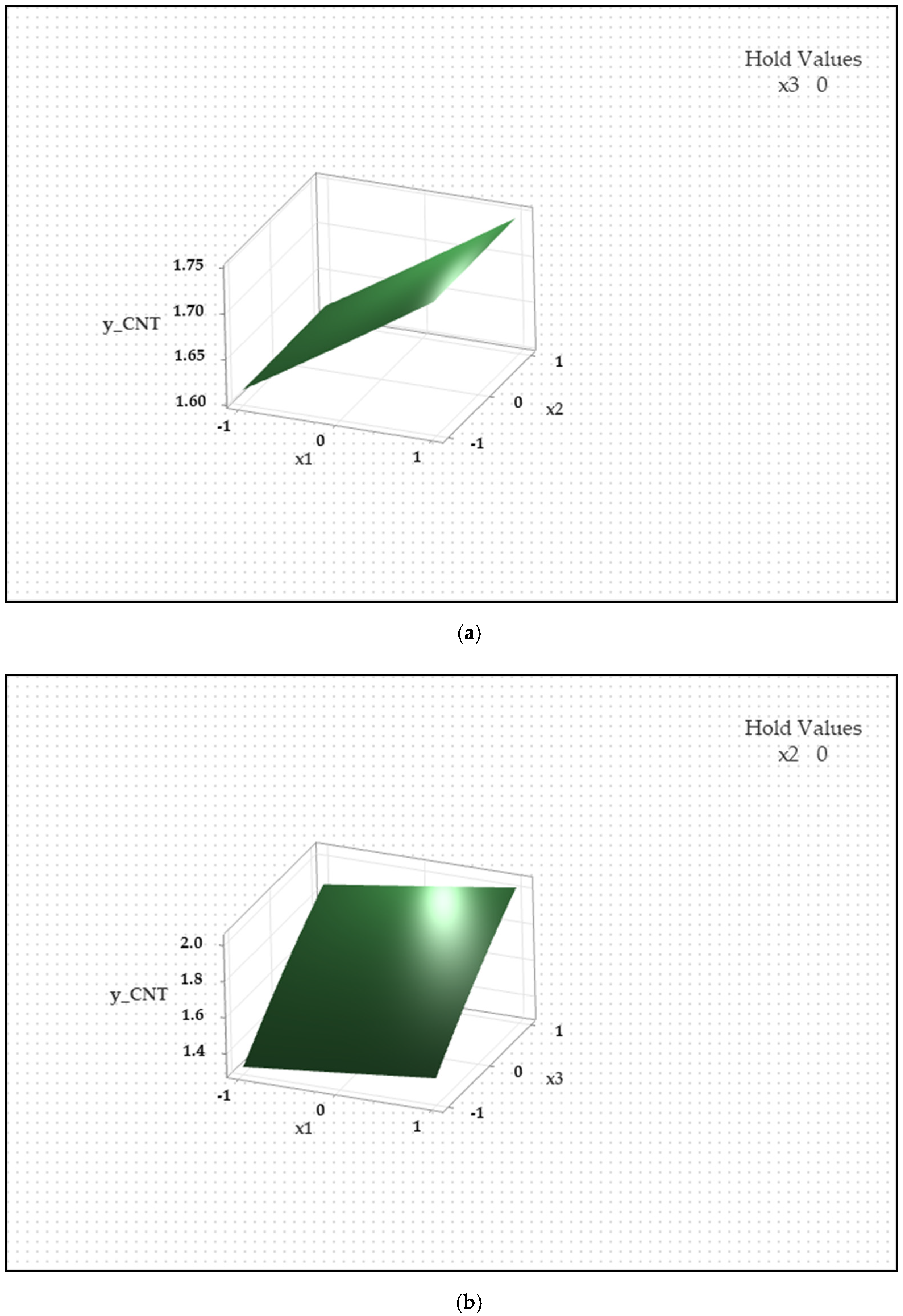
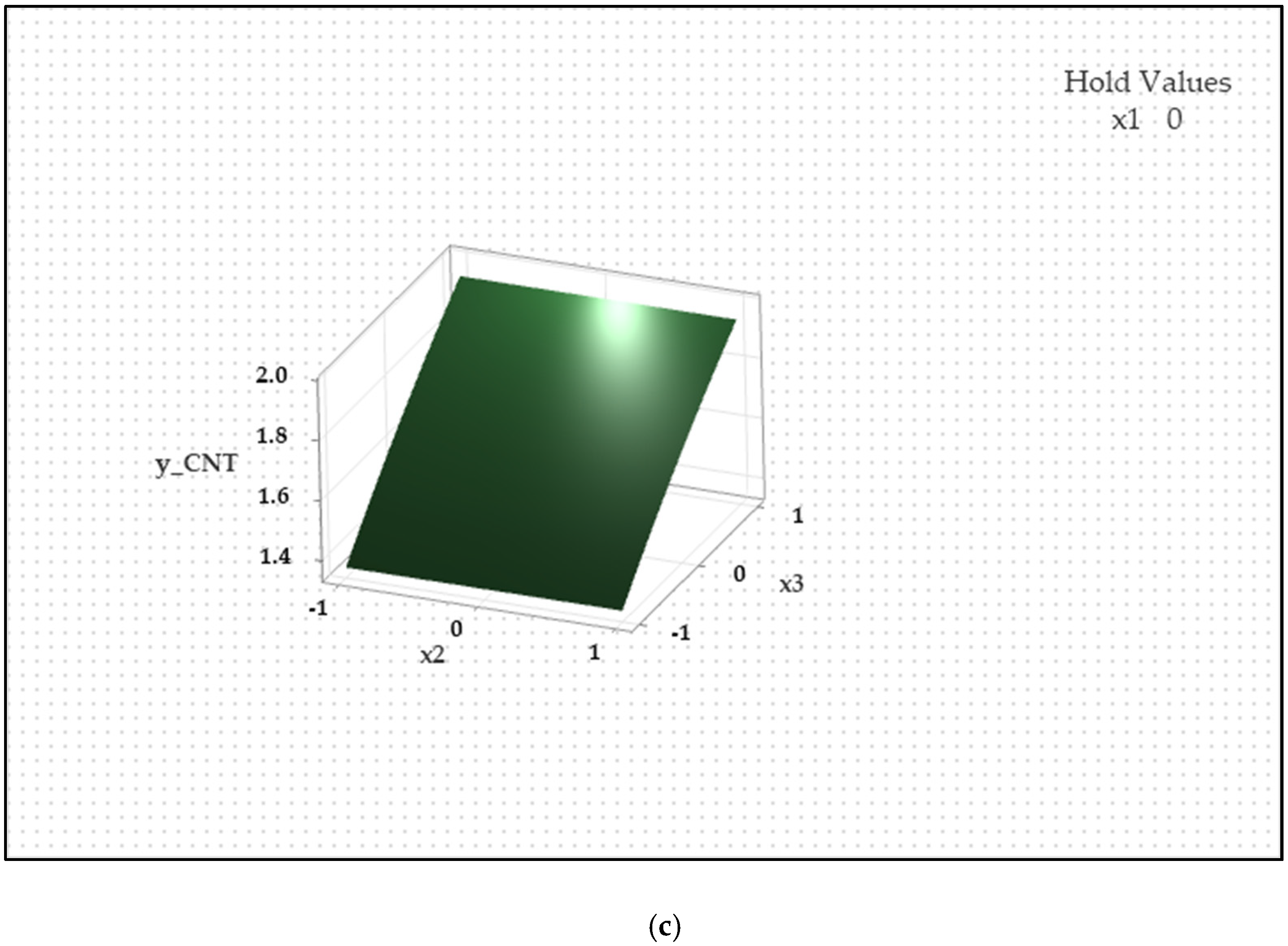
For the purpose of ascertaining the most ideal magnetic parameter for this model, we provide a novel approach to quantifying the maximum heat transfer rate. To achieve optimal heat transfer, we use the response surface methodology (RSM) with the desirability function approach to design the numerical experiment. The use of the RSM approach has not been implemented in the models previously mentioned. The face-centred composite design (CCF) is employed to build a design of experiment (DOE) that incorporates other possible controllable factors. The objective of this DOE is to maximise the heat transmission capacity using a quadratic regression model. Matsui’s study [40] indicates that the quadratic regression model is more adaptable than the linear regression model for assessing the interplay of several factors and responses to predict the best values of these interactions. To conduct the numerical analysis, we use the bvp4c function built in MATLAB, whereas the RSM analysis is carried out using Minitab. Since the integration of numerical approaches with RSM has garnered very little attention from scholars, this is an opportunity for further exploration of this combination. Both the numerical and RSM strategies that are built into this model may contribute to a comprehensive knowledge of the relationship between computational and experimental studies.

2. Formulation of the Model

2.1. Mathematical Formulation

In order to govern the boundary layer equations, which are organised into nonlinear partial differential equations (PDEs), we establish the following assumptions:
  • The flow experiences an incompressible, steady, and laminar flow without a slip effect.
  • The flow is described in two-dimensional (2D) space, with x and y acting as the axes on the cartesian coordinates.
  • The sheet is extended and contracted with the free stream velocity U ( x ) and the stretching or shrinking velocity U w ( x ) .
  • The terms U ( x ) and U w x can be written as U x = a x n and U w x = b x n , where a , b and n are positive constants, such that a , b > 0 and n > 1 .
  • The sheet is surrounded by the constant surface temperature T w and the constant ambient hybrid CNT nanofluids temperature T .
  • Temperature does not affect the thermophysical properties of hybrid CNTs.
  • The size of SWCNTs and MWCNTs is not varied, and there is no issue of agglomeration in the flow.
To design our model, Anuar et al.’s study [36] is adopted, and the effect of the magnetic field on the strength B 0 in the dimensionless unit is taken into consideration in the flow, where B 0 2 x n 1 = B 2 . However, the influence of an induced magnetic field is neglected. By setting u and v as the velocity components that are dependent on x and y , our model with specific boundary conditions is defined as follows:
u x + v y = 0 ,
u u x + v u y = U d U d x + μ h n f ρ h n f 2 u y 2 + σ h n f ρ h n f B 2 U u ,
u T x + v T y = α h n f 2 T y 2 ,
subjected to
u = U w ,   v = 0 ,   T = T w   at   y = 0 , u U ,   T T   as   y .
The variables u and v in Equations (1)–(4) represent the component velocities that are dependent on the Cartesian coordinates x and y . These components are written in non-dimensional units using the following equations:
u = ψ y ,   v = ψ x .
The terms μ h n f , ρ h n f and σ h n f in Equation (2) indicate the dynamic viscosity, density and electrical conductivity of hybrid CNT nanofluids, while α h n f in Equation (3) illustrates the thermal diffusivity of hybrid CNT nanofluids.

2.2. Non-Dimensional Similarity Ordinary Equations

To reduce the complexity of solving the above model, we introduce several similarity variables that were employed by Anuar et al. [36]. These variables play a vital role in transforming the PDEs system into the non-dimensional ordinary differential equations (ODEs) model. Crank [41] asserts that by converting PDEs into ODEs, it is possible to examine the physical system of fluid flow and heat transfer using a less complex system. This claim was supported by Burden and Faires [42] who said that ODEs are more numerically stable than PDEs. The introduction of these similarity variables can be deployed in the following expressions:
η = b n + 1 2 ν f 1 2 y x n 1 2 ,   ψ = 2 b ν f n + 1 1 2 x n + 1 2 f η ,   T = T + T w T θ η .
By inserting Equation (6) into Equations (2)–(5), we discover the following system of ordinary differential equations (ODEs).
A 1 f + f f A 2 f 2 1 + A 3 A 4 1 f = 0 ,
1 P r A 5 θ + f θ = 0 ,
subject to boundary conditions:
f η = ε ,   f η = 0 ,   θ η = 1 ,   at   η = 0 , f ( η ) 1 ,   θ η 0 ,   as   η .
The term A i , for i = 1 , 2 , 3 , 4 , 5 can be recorded as below:
A 1 = μ h n f / μ f ρ h n f / ρ f ,   A 2 = 2 n n + 1 ,   A 3 = σ h n f / σ f ρ h n f / ρ f ,   A 4 = 2 M n + 1 ,   A 5 = k h n f / k f ( ρ C p ) h n f / ( ρ C p ) f ,
where n , M and ε = a / b are the nonlinear, magnetic and stretching/shrinking velocity parameters, respectively, in dimensionless units. f and θ are functions of η . Hence, we can differentiate f with respect to η to obtain f , f and f , and differentiate θ with respect to η to obtain θ and θ . Referring to Jaafar et al. and Khashi’ie et al. [37,38], the term M in Equation (10) can be denoted as M = σ f ρ f B 0 2 b . To measure the physical quantities that can be applied in studying the application of the model, we define the local skin friction coefficient, C f , and the local Nusselt number, N u x , in the following equations:
C f = τ w ρ f U 2 ,
and
N u x = x q w k f ( T w T ) ,
where τ w and q w represent the surface shear stress and the surface heat flux, respectively. The terms τ w and q w can be written as
τ w = μ h n f u y ,   at   y = 0 ,
and
q w = k h n f T y ,   at   y = 0 .
Applying the similarity variables from Equation (6), we obtain the reduced skin friction and heat transfer coefficients, respectively, in Equations (15) and (16) as follows:
C f R e x 1 / 2 = A 6 f 0 ,
and
N u x R e x 1 / 2 = A 7 θ ( 0 ) ,
where A 6 = μ h n f / μ f n + 1 / 2 1 / 2 and A 7 = k h n f / k f n + 1 / 2 1 / 2 . We use the thermophysical properties of A 1 ,   A 2 ,   A 3 , A 4 ,   A 5 ,   A 6 and A 7 from Xue’s model (thermal conductivity), Maxwell’s model (electrical conductivity), Devi and Devi’s model and Bazbouz et al. [43]. The mathematical correlation of the thermal conductivity of hybrid CNTs in this model is also drawn from the most up-to-date research on hybrid CNTs conducted by Aladdin et al. [11] and Haider et al. [44]. The correlations and specific numeric values for the physical properties can be viewed in Table 1 and Table 2.

2.3. Numerical Procedure

For the purpose of being able to numerically solve Equations (7)–(9), the higher-order dimensionless ODEs are altered into first-order ODEs. This approach allows for the model to be entered into the bvp4c function in MATLAB. The transformation process is initiated by establishing the following equations:
f = y 1 ,   f = y 2 ,   f = y 3 , θ = y 4 ,   θ = y 5 .
Therefore, the higher orders of dimensionless f and θ are expressed as follows:
f = 1 A 1 y 1 y 3 A 2 y 2 y 2 1 + A 3 A 4 1 y ( 2 ) , θ = P r A 5 ( y 1 y ( 5 ) ) .
The boundary conditions pointed out in Equation (9) turn into these mathematical expressions:
y a 1 = 0 , y a 2 ε = 0 ,   y a 4 1 = 0 ,   at   η = 0 , y b 2 1 = 0 ,   y b 4 = 0 ,   a s   η .

2.4. Optimisation Procedure

To conduct the optimisation procedures, we apply the Response Surface Methodology (RSM). According to Myres et al. [45], the adoption of RSM can boost the efficiency of experimental and numerical operations by offering optimum solutions based on statistical and mathematical concepts. Researchers such as Benim et al. [46] successfully manipulated the RSM to optimise the aerofoil profiles in wind turbines.
To begin the optimisation process, we first identify three factors or parameters that have the potential to impact the heat transfer performance. According to Equations (7)–(10), the volume fraction, magnetic and nonlinear parameters are selected as the elements in the input set. These parameters are recognised as the most significant inputs that may contribute to the model’s performance. Additionally, the Tiwari and Das model emphasises that the volume parameter is the key factor in determining the fluid flow and heat transmission characteristics. Adhering to this model in developing the mathematical model has become the main reason for choosing this parameter as part of the input set. The matrix of these factors with different levels is illustrated in Table 3. Table 3 is organised according to the relative limitations of each parameter. + 1 = [ 1 ] stands for the highest level, 0 for the middle level and 1 for the lowest level. Numerical simulations are used to produce the output responses of hybrid y h C N T and mono y C N T CNTs nanofluids by systematically altering the values of the factors. We also utilise a face-centred central composite design (CCF) to create an experimental design, with the number of trials N calculated using the formula below:
N = 2 F + 2 F + C ,
where F and C are the number of factors and the centre point, respectively.
After screening the factors and their output variables, we develop the multivariate quadratic regression equations by modifying the quadratic model expressed previously by Myres et al. [45] in order to investigate the relationship between factors and their response variables. These equations are also formed to optimise the heat transfer for both hybrid and mono CNT nanofluids. The regression models of y h C N T and y C N T are written as follows:
y h C N T = β 0 + β 1 ϕ h n f + β 2 M + β 3 n + β 4 ϕ h n f 2 + β 5 M 2 + β 6 n 2 + β 7 ϕ h n f M + β 8 ϕ h n f n + β 9 M n + ϵ ,
and
y C N T = β 0 + β 1 ϕ n f + β 2 M + β 3 n + β 4 ϕ n f 2 + β 5 M 2 + β 6 n 2 + β 7 ϕ n f M + β 8 ϕ n f n + β 9 M n + ϵ .
The terms β 0 , β i ,   i = 1 , 2 , 3 , β j ,   j = 4 , 5 , 6 , β k ,   k = 7 , 8 , 9 and ϵ represent the mean value, the linear coefficients, the interaction between factors coefficients, the quadratic coefficients and the error term, respectively. The mathematical formulation of Equations (21) and (22), which include quadratic components, can be helpful in our analysis to determine the optimal amount of the heat transfer coefficient. According to Myres et al. [45], a quadratic model is suitable for fitting the process of an optimal issue. To determine the value of coefficients in Equations (21) and (22), we use the analysis of variance (ANOVA). The ANOVA data for the y h C N T and y C N T models are computed with the aid of the Minitab program.

3. Results and Discussions

3.1. Numerical Solutions

To validate the programming code developed in the bvp4c function (MATLAB), we compare the data with Anuar et al.’s model [36]. By setting ϕ S W C N T = ϕ M W C N T = M = 0 ,   n = 1 ,   ε = 1.1 , and Pr = 0.7 , the model produces the reduced skin friction f ( 0 ) and the reduced heat transfer θ ( 0 ) as displayed in Table 4. The results presented in Table 4 indicate that the current model and the previous model are in good agreement. The result of this agreement gives us the opportunity to commence our investigation by examining the effects of magnetic fields on the heat transfer and flow characteristics of the hybrid CNTs.
In order to examine the effect of the magnetic parameter M on the flow separation, it is necessary to identify the region in which the duality solution occurs. It is possible to predict the point at which the boundary layer separates from the surface using the dual solution. We assume that the upper solution (the first solution) and the lower solution (the second solution) are the attached and separated flow solutions, respectively. To investigate this region, we set M to vary from 0 to 0.2 and − 1.5 < ε < 1.5 . The Waqas et al. model [47] serves as a guide for changing the variable M . The other parameters are kept at constant values, where P r = 6.2 , ϕ 1 = ϕ S W C N T = 0.01 , ϕ 2 = ϕ M W C N T = 0.01 and n = 2 . The first solution (solid line) and the second solution (dash line) appear when ε c ε < 0 , where ε is in shrinking mode and ε c represents the critical point of producing the dual solutions. These phenomena are visually represented in Figure 2. An additional observation that can be made from this figure is that the boundary layer delays being separated as M increases. Increasing n also results in a noticeable lag in the detachment of boundary layers, as displayed in Figure 3. The aforementioned outcomes are produced through the configuration of various values for n and ε while holding all other variables constant. From Figure 2 and Figure 3, the rise of M and n contributes to the widening range of f ( 0 ) and θ 0 .
The variations in velocity f ( η ) and temperature θ ( η ) profiles for hybrid CNTs nanofluids resulting from the modifications in M and n can be demonstrated in Figure 4 and Figure 5, respectively. In Figure 4, the value of M is modified from 0 to 0.2, while in Figure 5, the value of n is adjusted from 2 to 4. We noticed that both figures (4 and 5) generate the dual solution when the sheet moves at stretching velocity ( ε < 0 ), where the first solution is thinner than the second solution. Figure 4 and Figure 5 also provide strong evidence that the profiles asymptotically meet the boundary constraints specified in Equation (9). The velocity profile f ( η ) for the first solution has an increasing trend as the values of M and n grow. But the rise in the values of M and n leads to a distinct pattern in the profile of f ( η ) for the second solution. To illustrate the thermal boundary layer of the first solution, we discover that an increase in M and n results in a drop in θ ( η ) . However, the value of θ ( η ) for the second solution gets higher as a consequence of the increase in M .
The performance of hybrid CNTs both for the skin friction and heat transfer rate under the impact of M , ϕ 1 = ϕ S W C N T , and ϕ 2 = ϕ M W C N T are discussed in Figure 6. The values of M are set at 0, 0.1 and 0.2, while ϕ 1 and ϕ 2 vary from 0 to 0.1. The values of ϕ 1 and ϕ 2 undergo modifications at low concentrations, as shown by Kumar et al. [48]. They believe that the performance of the transfer is effectively enhanced under low-concentration conditions. The other parameters are held constant, with P r = 6.2 , ε = 0.5 and n = 2 . Based on this figure, we identified that the rise in M , ϕ 1 and ϕ 2 triggers a boost in both the skin friction and heat transfer coefficients. Prior research conducted by Sun et al. [49] demonstrated the enhancement of heat transfer resulting from the application of a magnetic field. According to Shah et al. [50], they stated that the magnetic field induces an increase in heat transfer via the action of Lorentz forces.
With the goal of evaluating the performance of hybrid carbon nanotubes (CNTs) nanofluids with mono-CNTs nanofluids in terms of skin friction and heat transfer, we conduct investigations utilising various values of ϕ 1 , ϕ 2 and M . To choose the most suitable nanoparticles that effectively act as mono-CNTs, we adhere to Samat et al.’s model [51]. They found that SWCNTs were better at transferring heat than MWCNTs. This means that SWCNTs represent mono-CNTs. By leaving P r at 6.2 and n = 2 , we can discover from Figure 7 and Figure 8 that the skin friction and heat transfer coefficients for hybrid CNTs nanofluids and mono-CNTs nanofluids both rise. Furthermore, hybrid carbon nanotubes (CNTs) nanofluids exhibit superior performance compared to mono-CNTs nanofluids in terms of both skin friction and heat transfer coefficients.

3.2. RSM

In order to compute the numerical values of the responses y h C N T and y C N T , we employ a mixture of several parameter levels, including ϕ h n f , ϕ n f , M and n . The distribution of various values of these independent variables and their corresponding responses is shown in Table 5. Employing Equation (20) with F = 3 , C = 6 , we perform 20 trials. The numerical findings arranged in Table 5 are tested using the analysis of variance (ANOVA) in Minitab.
The ANOVA results in analysing the heat transfer coefficients for hybrid CNTs and mono CNTs are displayed in Table 6 and Table 7 and Figure 9, Figure 10, Figure 11, Figure 12, Figure 13 and Figure 14. Both models, y h C N T and y C N T , are considered well-fitting models as their residuals are normally distributed. According to Myres et al. [45], the model is statistically significant if the P -value of the sources is less than 0.05. Since the P -values of the several inputs in Table 6 and Table 7 exceed 0.05, we exclude these factors when establishing the reduced models for hybrid CNTs and mono CNTs. The reduced models for hybrid CNTs and mono CNTs are constructed in Table 8 and Table 9, respectively.
After removing these terms, the ANOVA results in Table 8 and Table 9 show that all the sources have p-values less than 0.05. As a consequence, the reduced models fit statistically to produce the optimal solution for heat transfer y h C N T and y C N T . Therefore, we have productively formulated the final quadratic regression equations of the heat transfer for hybrid CNTs in Equation (23) and mono CNTs in Equation (24). The equations are written as follows:
y h C N T = 1.81639 + 0.129914 ϕ h n f + 0.001125 M + 0.313135 n + 0.004701 ϕ h n f 2 0.027299 n 2 + 0.024337 ϕ h n f n ,
y C N T = 1.67915 + 0.064819 ϕ n f + 0.000988 M + 0.289030 n + 0.000907 ϕ n f 2 0.025219 n 2 + 0.011281 ϕ n f n .
The satisfactory outcomes shown in Table 8 and Table 9 also enable the determination of the ideal solutions for heat transmission in both kinds of nanofluids. Utilising the response optimizer, the rate of heat transfer for hybrid CNTs and mono CNTs is maximised when ϕ h n f , ϕ n f , M and n are at their highest values. With a composite desirability value of 100%, Table 10 and Table 11 reveal that hybrid CNTs have excellent heat transmission performance compared to individual CNTs. In terms of heat transfer, this result shows that the RSM has successfully confirmed the previous computational findings. These findings show that hybrid carbon nanotubes (CNTs) are better than mono CNTs.

4. Conclusions

The investigation of hybrid CNTs flow and heat transfer past a nonlinear stretching or shrinking sheet is successfully performed using the numerical and RSM approaches under the influence of magnetohydrodynamic effects. The model is developed by taking the magnetic and volume fractions of hybrid and mono CNTs, nonlinear, and shrinking or stretching parameters as the leading variables in non-dimensionless units. The similarity equations in the form of non-dimensional ordinary differential equations are solved using the similarity variables method. The bvp4C MATLAB function is employed to numerically compute the first order of the ODEs system. By referring to the mathematical model and using the numerical experiment data, the design of the heat transfer coefficients both for hybrid CNTs and mono CNTs is statistically optimised in Minitab. The design of this optimisation procedure involves three parameters and twenty simulation runs. The findings show that:
  • The multiple solution is generated when the sheet moves nonlinearly in the shrinking region where ε c ε < 0 .
  • The boundary layer of the first solution is thinner than that of the second solution.
  • The model may provide a couple of solutions when the magnetic parameter is below 1.
  • The magnetic and non-linear parameters delay the occurrence of boundary layer separation and expand the range of potential solutions for the reduced skin friction f 0 and the reduced heat transfer θ 0 .
  • The magnetic and hybrid CNTs volume fraction parameters enhance the favourable effect on skin friction and heat transfer coefficients.
  • To maximise the heat transfer rate, the magnetic, nonlinear, and hybrid CNTs volume fractions are set at their greatest values.
  • Hybrid CNTs are superior to mono CNTs for the skin friction coefficient.
  • The numerical analysis and response surface methodology demonstrate that hybrid CNTs are better than mono CNTs with regard to the heat transfer rate.

5. Future Works

Due to some limitations in this model, there are several recommendations to extend the model in the future. They are as follows:
  • The investigation of hybrid nanofluids flow-based carbon nanotubes over a nonlinear stretching/shrinking sheet under an unsteady flow case.
  • The study of hybrid carbon nanotube flow across a nonlinear stretching/shrinking sheet using the 3-Dimension (3D) flow approach.
  • The examination of hybrid nanofluids flow-based carbon nanotubes over a nonlinear stretching/shrinking sheet with distinct effects, including velocity and thermal slip effects.
  • The exploration of hybrid carbon nanotube flow past different geometric configurations, such as a Riga plate.
The suggestions mentioned above for future research could potentially improve the comprehension of the fluid motion and heat transfer characteristics of hybrid nanofluids, particularly for hybrid carbon nanotubes.

Author Contributions

N.A.A.S. contributed to the research concept, the design of the study, the preparation of materials, data collection, the analysis of findings, and the writing of the first draft of the article. N.B. validated the research concept, the design of the study, the preparation of materials, data collection, the analysis of findings, and the review of the first draft of the article. N.M.A. validated the research concept and the design of the study. All authors have read and agreed to the published version of the manuscript.

Funding

This research received no external funding.

Data Availability Statement

The data presented in this study are available on request from the corresponding author.

Acknowledgments

We would like to extend our deepest gratitude to the Malaysian Ministry of Higher Education (MOHE) throughout this journey to complete this article. We also express our gratitude for all the positive and encouraging reviews and comments.

Conflicts of Interest

The authors declare no conflicts of interest.

Abbreviations

NomenclatureGreek Symbols
P r Prandtl number α Thermal diffusivity
T Constant temperature μ Dynamic viscosity
U Constant velocity ρ Density
M Dimensionless magnetic parameter θ Dimensionless temperature
n Dimensionless nonlinear parameter ψ Dimensionless stream function
N u x Local Nusselt number η Dimensionless thickness
R e x Local Reynolds number C p Specific heat for base fluid
C f Skin friction coefficient β Regression coefficients
R e s Response k Thermal conductivity
u , v Velocity components ν Kinematic viscosity
x ,   y Cartesian coordinates system ϕ Dimensionless nanoparticles volume fraction
B 0 Dimensionless magnetic strength ε Dimensionless stretching/shrinking parameter
CNTsCarbon nanotubes ε c Critical value
f Dimensionless function ϵ Error term
F The number of factors
C Center points
Subscripts
w Condition on the sheet wall
Ambient condition
h n f Hybrid nanofluids
n f Nanofluids
f Base fluid
n f Nanofluids
h n f Hybrid Nanofluids
S W C N T Single-walled carbon nanotubes
M W C N T Multi-walled carbon nanotubes
1 Single-walled carbon nanotubes
2 Multi-walled carbon nanotubes
C N T Mono-carbon nanotubes
h C N T Hybrid carbon nanotubes

References

  1. Choi, U.S. Enhancing Thermal Conductivity of Fluids with Nanoparticles, Developments and Application of Non-Newtonian Flows. ASME J. Heat Transf. 1995, 66, 99–105. [Google Scholar]
  2. Turcu, R.; Darabont, A.L.; Nan, A.; Aldea, N.; Macovei, D.; Bica, D.; Vekas, L.; Pana, O.; Soran, M.L.; Koos, A.; et al. New Polypyrrole-Multiwall Carbon Nanotubes Hybrid Materials. J. Optoelectron. Adv. Mater. 2006, 8, 643–647. [Google Scholar]
  3. Reddy, V.S.; Kandasamy, J.; Sivanandam, S. Stefan Blowing Impacts on Hybrid Nanofluid Flow over a Moving Thin Needle with Thermal Radiation and MHD. Computation 2023, 11, 128. [Google Scholar] [CrossRef]
  4. Devi, S.P.A.; Devi, S.S.U. Numerical Investigation of Hydromagnetic Hybrid Cu-Al2O2/Water Nanofluid Flow over a Permeable Stretching Sheet with Suction. Int. J. Nonlinear Sci. Numer. Simul. 2016, 17, 24–257. [Google Scholar] [CrossRef]
  5. Khashi’ie, N.S.; Arifin, N.M.; Nazar, R.; Hafidzuddin, E.H.; Wahi, N.; Pop, I. Magnetohydrodynamics (MHD) Axisymmetric Flow and Heat Transfer of a Hybrid Nanofluid Past a Radially Permeable Stretching/Shrinking Sheet with Joule Heating. Chin. J. Phys. 2020, 64, 251–263. [Google Scholar] [CrossRef]
  6. Khashi’ie, N.S.; Hafidzuddin, E.H.; Md Arifin, N.; Wahi, N. Stagnation Point Flow of Hybrid Nanofluid over a Permeable Vertical Stretching/Shrinking Cylinder with Thermal Stratification Effect. CFD Lett. 2021, 12, 80–94. [Google Scholar]
  7. Sajid, M.U.; Ali, H.M. Thermal Conductivity of Hybrid Nanofluids: A Critical Review. In. J. Heat Mass Transf. 2018, 126, 211–234. [Google Scholar] [CrossRef]
  8. Navrotskaya, A.G.; Aleksandrova, D.D.; Krivoshapkina, E.F.; Sillanpaa, M.; Krivoshapkin, P.V. Hybrid Materials Based on Carbon Nanotubes and Nanofibers for Environmental Applications. Front. Chem. 2020, 8, 00546. [Google Scholar] [CrossRef]
  9. Al-Hanaya, A.M.; Sajid, F.; Abbas, N. Effect of SWCNT and MWCNT on the Flow of Micropolar Hybrid Nanofluid over a Curved Stretching Surface with Induced Magnetic Field. Sci. Rep. 2020, 10, 8488. [Google Scholar] [CrossRef]
  10. Sulochana, C.; Kumar, T.P. Heat Transfer of SWCNT-MWCNT Based Hybrid Nanofluid Boundary Layer Flow with Modified Thermal Conductivity Model. J. Adv. Res. Fluid Mech. Therm. Sci. 2022, 92, 13–24. [Google Scholar] [CrossRef]
  11. Aladdin, N.A.L.; Bachok, N. Duality Solutions in Hydromagnetic Flow of SWCNT-MWCNT/Water Hybrid Nanofluid over Vertical Moving Slender Needle. Mathematics 2021, 9, 2927. [Google Scholar] [CrossRef]
  12. Tabassum, R.; Al-Zubaidi, A.; Rana, S.; Mehmood, R.; Saleem, S. Slanting Transport of Hybrid (MWCNTs-SWCNTs/H2O) Nanofluid Upon a Riga Plate with Temperature Dependent Viscosity and Thermal Jump Condition. Int. Commun. Heat Mass Transf. 2022, 135, 106165. [Google Scholar] [CrossRef]
  13. Svorcan, J.; Wang, J.M.; Griffin, K.P. Current State and Future Trends in Boundary Layer Control on Lifting Surfaces. Adv. Mech. Eng. 2022, 14, 1–23. [Google Scholar] [CrossRef]
  14. Shateyi, S.; Muzara, H. On The Numerical Analysis of Unsteady MHD Boundary Layer Flow of Williamson Fluid over a Stretching Sheet and Heat and Mass Transfers. Computation 2020, 8, 55. [Google Scholar] [CrossRef]
  15. Lund, L.A.; Omar, Z.; Khan, I.; Sherif, E.S.M. Dual Solutions and Stability Analysis of Aa Hybrid Nanofluid over a Stretching/Shrinking Sheet Executing MHD Flow. Symmetry 2020, 12, 276. [Google Scholar] [CrossRef]
  16. Rosca, N.C.; Rosca, A.V.; Aly, E.H.; Pop, I. Flow and Heat Transfer Past a Stretching/Shrinking Sheet Using Modified Buongiorno Nanoliquid Model. Mathematics 2021, 9, 3047. [Google Scholar] [CrossRef]
  17. Dinarvand, S.; Yousefi, M.; Chamkha, A.J. Numerical Simulation of Unsteady Flow toward a Stretching/Shrinking Sheet in Porous Medium Filled with a Hybrid Nanofluid. J. Appl. Comput. Mech. 2022, 8, 11–20. [Google Scholar]
  18. Samat, N.A.A.; Bachok, N.; Arifin, N.M. The Significant Effect of Hydromagnetic on Carbon Nanotubes Based Nanofluids Flow and Heat Transfer Past a Porous Stretching/Shrinking Sheet. J. Adv. Res. Fluid Mech. Therm. Sci. 2023, 106, 51–64. [Google Scholar]
  19. Crane, L.J. Flow Past a Stretching Plate. J. Appl. Math. Phys. 1970, 21, 645–647. [Google Scholar] [CrossRef]
  20. Vajravelu, K.; Mukhopadhyay, S. Flow Past a Shrinking Sheet. In Fluid Flow, Heat and Mass Transfer at Bodies of Different Shapes: Numerical Solutions, 1st ed.; Vajravelu, K., Mukhopadhyay, S., Eds.; Academic Press: Cambridge, UK, 2016; pp. 47–76. [Google Scholar]
  21. Nayakar, S.; Mahabaleshwar, U.; Vinaykumar, P.; Lorenzini, G.; Baleanu, D. Nonlinear Stretching/Shrinking Cooling of a Sheet Involving an MHD Walters’ Liquid B with Suction. Math. Model. Eng. Probl. 2019, 6, 343–348. [Google Scholar] [CrossRef]
  22. Abd Rahman, N.H.; Bachok, N.; Rosali, H. MHD Stagnation Point Flow over a Nonlinear Stretching/Shrinking Sheet in Nanofluids. J. Adv. Res. Fluid Mech. Therm. Sci. 2020, 76, 139–152. [Google Scholar] [CrossRef]
  23. Ragupathi, P.; Saranya, S.; Hakeem, A.K.A. Second-Order Slip and Thermal Jump Effects on MHD Flow of Nanosecond Grade Fluid Flow Over a Stretching Sheet. In Advances in Fluid Dynamics. Selected Proceedings of the International Conference on Applications of Fluid Dynamics (ICAFD 2018); Springer: Singapore, 2021; pp. 457–467. [Google Scholar]
  24. Saranya, S.; Ragupathi, P.; Al-Mdallal, Q. Analysis of Bio-Convective Heat Transfer over an Unsteady Curved Stretching Sheet Using the Shifted Legendre Collocation Method. Case Stud. Therm. Eng. 2022, 39, 102433. [Google Scholar] [CrossRef]
  25. Mahabaleshwar, U.S.; Sneha, K.N.; Souayeh, B. Flow Due to a Porous Stretching/Shrinking Sheet with Thermal Radiation and Mass Transpiration. Heat Tranf. 2022, 51, 5441–5546. [Google Scholar] [CrossRef]
  26. Aly, E.M.; Pop, I. MHD Flow and Heat Transfer Near Stagnation Point over a Stretching/Shrinking Surface with Partial Slip and Viscous Dissipation: Hybrid Nanofluid Versus Nanofluid. Powder Technol. 2020, 367, 192–205. [Google Scholar] [CrossRef]
  27. Khan, U.; Zaib, A.; Bakar, S.A.; Ishak, A. Stagnation-Point Flow of a Hybrid Nanoliquid over a Non-Isothermal Stretching/Shrinking Sheet with Characteristics of Inertial and Microstructure. Case Stud. Therm. Eng. 2021, 26, 101150. [Google Scholar] [CrossRef]
  28. Zainal, N.A.; Waini, I.; Khashi’ie, N.S.; Kasim, A.R.M.; Naganthran, K.; Nazar, R.; Pop, I. Stagnation Point Hybrid Nanofluid Flow Past a Stretching/Shrinking Sheet Driven by Arrhenius Kinetics and Radiation Effect. Alex. Eng. J. 2023, 68, 29–38. [Google Scholar] [CrossRef]
  29. Waini, I.; Ishak, A.; Pop, I. Hybrid Nanofluid Flow and Heat Transfer Past a Permeable Stretching/Shrinking Surface with a Convective Boundary Condition. J. Phys. Conf. Ser. 2019, 1366, 012022. [Google Scholar] [CrossRef]
  30. Jawad, M.; Jan, R.; Boulaaras, S.; Amin, I.; Shah, N.A.; Idris, S.A. Unsteady Electrohydrodynamic Stagnation Point Flow of Hybrid Nanofluid Past a Convective Heated Stretch/Shrink Sheet. Adv. Math. Phys. 2021, 2021, 6229706. [Google Scholar] [CrossRef]
  31. Merkin, J.H.; Pop, I. Stagnation Point Flow Past a Stretching/Shrinking Sheet Driven by Arrhenius Kinetics. Appl. Math. Comput. 2018, 337, 583–590. [Google Scholar] [CrossRef]
  32. Alekseev, V.; Tang, Q.; Vasilyeva, M.; Chung, E.T.; Efendiev, Y. Mixed Generalized Multiscale Finite Element Method for a Simplified Magnetohydrodynamics Problem in Perforated Domains. Computation 2020, 8, 58. [Google Scholar] [CrossRef]
  33. Ragupathi, P.; Saranya, S.; Hakeem, A.K.A.; Ganga, B. Numerical Analysis on the Three-Dimensional Flow and Heat Transfer of Multiple Nanofluids Past a Riga Plate. J. Phys. Conf. Ser. 2021, 1850, 012044. [Google Scholar] [CrossRef]
  34. Mahabaleshwar, U.S.; Sneha, K.N.; Chan, A.; Zeidan, D. An Effect of MHD Fluid Flow Heat Transfer Using CNTs with Thermal Radiation and Heat Source/Sink Across a Stretching/Shrinking Sheet. Int. Commun. Heat Mass Transf. 2022, 135, 106080. [Google Scholar] [CrossRef]
  35. Mahesh, R.; Mahabaleshwar, U.S.; Sofos, F. Influence of Carbon Nanotube Suspensions on Casson Fluid Flow over a Permeable Shrinking Membrane: An Analytical Approach. Sci Rep. 2023, 13, 3369. [Google Scholar] [CrossRef] [PubMed]
  36. Anuar, N.S.; Bachok, N.; Md Arifin, N.; Rosali, H. Numerical Solution of Stagnation Point Flow and Heat Transfer over a Nonlinear Stretching/Shrinking Sheet in Hybrid Nanofluid: Stability Analysis. J. Adv. Res. Fluid Mech. Therm. Sci. 2020, 76, 85–98. [Google Scholar] [CrossRef]
  37. Jaafar, A.; Waini, I.; Jamaludin, A.; Nazar, R.; Pop, I. MHD Flow and Heat Transfer of a Hybrid Nanofluid Past a Nonlinear Surface Stretching/Shrinking with Effects of Thermal Radiation and Suction. Chin. J. Phys. 2022, 79, 13–27. [Google Scholar] [CrossRef]
  38. Khashi’ie, N.S.; Arifin, N.M.; Pop, I. Magnetohydrodynamics (MHD) Boundary Layer Flow of Hybrid Nanofluid over a Moving Plate with Joule Heating. Alex. Eng. J. 2022, 61, 1938–1945. [Google Scholar] [CrossRef]
  39. Zafar, M.; Sakidin, H.; Sheremet, M.; Dzulkarnain, I.B.; Hussain, A.; Nazar, R.; Khan, J.A.; Irfan, M.; Said, Z.; Afzal, F.; et al. Recent Development and Future Prospective of Tiwari and Das Mathematical Model in Nanofluid Flow for Different Geometries: A Review. Processes 2023, 11, 834. [Google Scholar] [CrossRef]
  40. Matsui, H. Quadratic Regression for Functional Response Models. Econom. Stat. 2020, 13, 125–136. [Google Scholar] [CrossRef]
  41. Crank, J. The Mathematics of Diffusion, 2nd ed.; Oxford University Press: New York, NY, USA, 1975. [Google Scholar]
  42. Burden, R.L.; Faires, J.D. Numerical Analysis, 9th ed.; Cengage Learning: Boston, MA, USA, 2010. [Google Scholar]
  43. Bazbouz, M.B.; Aziz, A.; Copic, D.; Volder, M.D.; Welland, M.E. Fabrication of High Specific Electrical Conductivity and High Ampacity Carbon Nanotube/Copper Composite Wires. Adv. Electro. Mater. 2021, 7, 202001213. [Google Scholar] [CrossRef]
  44. Haider, S.M.A.; Ali, B.; Wang, Q.; Zhao, C. Rotating Flow and Heat Transfer of Single-Wall Carbon Nanotube and Multi-Wall Carbon Nanotube Hybrid Nanofluid with Base Fluid Water over a Stretching Sheet. Energies 2022, 15, 6060. [Google Scholar] [CrossRef]
  45. Myres, R.H.; Montgomery, D.C.; Anderson-Cook, C.M. Response Surface Methodology: Process and Product Optimization Using Designed Experiments, 3rd ed.; John Wiley & Sons: Hoboken, NJ, USA, 2009. [Google Scholar]
  46. Benim, A.C.; Diederich, M.; Pfeiffelmann, B. Aerodynamic Optimization of Airfoil Profiles for Small Horizontal Axis Wind Turbines. Computation 2018, 6, 34. [Google Scholar] [CrossRef]
  47. Waqas, H.; Wakif, A.; Al-Mdallal, Q.; Zaydan, M.; Farooq, U.; Hussain, M. Significance of Magnetic Field and Activation Energy on the Features of Stratified Mixed Radiative-Convective Couple-Stress Nanofluid Flows with Motile Microorganisms. Alex. Eng. J. 2022, 61, 1425–1436. [Google Scholar] [CrossRef]
  48. Kumar, J.P.; Umavathi, J.C.; Dhone, A.S. Forced Convection of Magnetohydrodynamic (MHD)—Boundary Layer Flow Past Thin Needle with Variable Wall Temperature Using Casson Nanofluid. J. Nanofluids 2023, 12, 271–279. [Google Scholar] [CrossRef]
  49. Sun, B.; Guo, Y.; Yang, D.; Li, H. The Effect of Constant Magnetic Field on Convective Heat Transfer of Fe3O4/Water Magnetic Nanofluid in Horizontal Circular Tubes. Appl. Therm. Eng. 2020, 171, 114920. [Google Scholar] [CrossRef]
  50. Shah, Z.; Hajizadeh, M.R.; Ikramullah; Alreshidi, N.A.; Deebani, W.; Shutaywi, M. Entropy Optimization and Heat Transfer Modeling for Lorentz Forces Effect on Solidification of NEPCM. Int. Commun. Heat Mass Transf. 2020, 117, 104715. [Google Scholar] [CrossRef]
  51. Samat, N.A.A.; Bachok, N.; Arifin, N.M. Carbon Nanotubes (CNTs) Nanofluids Flow and Heat Transfer under MHD Effect over a Moving Surface. J. Adv. Res. Fluid Mech. Therm. Sci. 2023, 103, 165–178. [Google Scholar] [CrossRef]
Figure 1. The schematic model of stagnation point flow over nonlinear (a) stretching sheet and (b) shrinking sheet.
Computation 12 00046 g001
Figure 2. Variation of solutions (a) f ( 0 ) ; (b) θ ( 0 ) using different values of ε and M in hybrid SWCNTs-MWCNTs water-based nanofluids.
Computation 12 00046 g002
Figure 3. Variation of solutions (a) f ( 0 ) ; (b) θ ( 0 ) using different values of ε and n in hybrid SWCNTs-MWCNTs water-based nanofluids.
Computation 12 00046 g003
Figure 4. Variation of solutions (a) velocity; (b) temperature profiles using different values of M in hybrid SWCNTs-MWCNTs water-based nanofluids.
Computation 12 00046 g004
Figure 5. Variation of solutions (a) velocity; (b) temperature profiles using different values of n in hybrid SWCNTs-MWCNTs water-based nanofluids.
Computation 12 00046 g005
Figure 6. Variation of solutions (a) skin friction; (b) heat transfer coefficients using different values of M and ϕ in hybrid SWCNTs-MWCNTs water-based nanofluids.
Computation 12 00046 g006
Figure 7. Comparison performance of hybrid CNTs and mono CNTs in (a) skin friction; (b) heat transfer coefficients using different values of ϕ 1 = ϕ S W C N T and ϕ 2 = ϕ M W C N T .
Computation 12 00046 g007
Figure 8. Comparison performance of hybrid CNTs and mono CNTs in (a) skin friction; (b) heat transfer coefficients using different values of M .
Computation 12 00046 g008
Figure 9. (a) Normal probability plot; (b) residual histogram for hybrid CNTs.
Computation 12 00046 g009aComputation 12 00046 g009b
Figure 10. Contour plots for the interaction of (a) x 1 and x 2 ; (b) x 1 and x 3 ; (c) x 2 and x 3 for hybrid CNTs.
Computation 12 00046 g010aComputation 12 00046 g010b
Figure 11. Surface plots for the interaction of (a) x 1 and x 2 ; (b) x 1 and x 3 ; (c) x 2 and x 3 for hybrid CNTs.
Computation 12 00046 g011aComputation 12 00046 g011b
Figure 12. (a) Normal probability plot; (b) residual histogram for mono CNTs.
Computation 12 00046 g012aComputation 12 00046 g012b
Figure 13. Contour plots for the interaction of (a) x 1 and x 2 ; (b) x 1 and x 3 ; (c) x 2 and x 3 for mono CNTs.
Computation 12 00046 g013aComputation 12 00046 g013b
Figure 14. Surface plots for the interaction of (a) x 1 and x 2 ; (b) x 1 and x 3 ; (c) x 2 and x 3 for mono CNTs.
Computation 12 00046 g014aComputation 12 00046 g014b
Table 1. The thermophysical characteristics and correlations of hybrid CNTs dispersed in water.
CharacteristicsCorrelations
Viscosity μ h n f = μ f 1 ϕ S W C N T 2.5 1 ϕ M W C N T 2.5
Density ρ h n f = 1 ϕ M W C N T 1 ϕ S W C N T ρ f + ϕ S W C N T ρ S W C N T + ϕ M W C N T ρ M W C N T
Heat Capacity ( ρ C p ) h n f = 1 ϕ M W C N T 1 ϕ S W C N T ( ρ C p ) f + ϕ S W C N T ( ρ C p ) S W C N T + ϕ M W C N T ( ρ C p ) M W C N T
Thermal Conductivity k h n f = 1 ϕ M W C N T + 2 ϕ M W C N T k M W C N T k M W C N T k n f ln k M W C N T + k n f k n f 1 ϕ M W C N T + 2 ϕ M W C N T k n f k M W C N T k n f ln k M W C N T + k n f k n f k n f ,
k n f = 1 ϕ S W C N T + 2 ϕ S W C N T k S W C N T k S W C N T k f ln k S W C N T + k f k f 1 ϕ S W C N T + 2 ϕ S W C N T k f k S W C N T k f ln k S W C N T + k f k f k f
Electrical Conductivity σ h n f = σ M W C N T + 2 σ n f 2 ϕ M W C N T σ n f σ M W C N T σ M W C N T + 2 σ n f + ϕ M W C N T σ n f σ M W C N T σ n f ,
σ n f = σ S W C N T + 2 σ f 2 ϕ S W C N T σ f σ S W C N T σ S W C N T + 2 σ f + ϕ S W C N T σ f σ S W C N T σ f
Table 2. The thermophysical characteristics of hybrid CNTs and water at room temperature.
CharacteristicsNanoparticlesBase Fluid
SWCNTsMWCNTsWater
Density, ρ (kg m−3)26001600997.1
Heat Capacity, C p (J kg−1 K−1)4257964179
Thermal Conductivity, k (W m−1 K−1)660030000.613
Electrical Conductivity, σ (S m−1)1.0 × 1083.5 × 1065.0 × 10−2
Table 3. Different levels of values of independent variables (factors).
Factors
ϕ h n f or ϕ n f   [ x 1 ] M   [ x 2 ] n   [ x 3 ]
0.03 [+1]0.3 [+1]5.0 [+1]
0.02 [0]0.2 [0]3.5 [0]
0.01 [−1]0.1 [−1]2.0 [−1]
Note: The symbol [] denotes a coded component.
Table 4. Comparison between the current model and Anuar et al.’s model [36].
n f ( 0 ) θ ( 0 )
Anuar et al.’s Model [36]The Present SolutionAnuar et al.’s Model [36]The Present Solution
1 1.1867 1.1867 0.1828 0.1828
Table 5. Design of experiment of heat transfer in hybrid CNTs and mono CNTs with water-based nanofluids.
RunsUncoded ParametersCoded ParametersResponses
ϕ h n f or ϕ n f M n x 1 x 2 x 3 y h C N T y C N T
10.010.12.0−1−1−11.36411.3112
20.030.12.01−1−11.59401.4178
30.010.32.0−11−11.36661.3136
40.030.32.011−11.59721.4204
50.010.15.0−1−111.94251.8673
60.030.15.01−112.26992.0190
70.010.35.0−1111.94401.8687
80.030.35.01112.27192.0206
90.010.23.5−1001.67951.6145
100.030.23.51001.96271.7457
110.020.13.50−101.81531.6782
120.020.33.50101.81741.6801
130.020.22.000−11.47661.3650
140.020.25.00012.10161.9428
150.020.23.50001.81641.6791
160.020.23.50001.81641.6791
170.020.23.50001.81641.6791
180.020.23.50001.81641.6791
190.020.23.50001.81641.6791
200.020.23.50001.81641.6791
Table 6. Analysis of variance for the full model of heat transfer in hybrid CNTs with water-based nanofluids.
SourceDFAdj SSAdj MS F -Valuep-Value
Model91.184110.131568158,942.790.000
Linear31.176310.392102473,685.110.000
x 1 10.195760.195760236,491.300.000
x 2 10.000010.00001315.300.003
x 3 10.980530.9805331,184,548.720.000
Square30.003070.0010221234.950.000
x 1 × x 1 10.000060.00006173.810.000
x 2 × x 2 10.000000.0000000.000.952
x 3 × x 3 10.002050.0020482473.550.000
2-Way Interaction30.004740.0015801908.330.000
x 1 × x 2 10.000000.0000000.170.691
x 1 × x 3 10.004740.0047385724.070.000
x 2 × x 3 10.000000.0000010.750.408
Error100.000010.000001
Lack-of-Fit50.000010.000002**
Pure Error50.000000.000000
Total191.18412
Note: The symbol * indicates that the data is too small.
Table 7. Analysis of variance for the full model of heat transfer in mono CNTs with water-based nanofluids.
SourceDFAdj SSAdj MS F -Valuep-Value
Model90.8814730.097941611,438.840.000
Linear30.8774070.2924691,825,856.010.000
x 1 10.0420150.042015262,298.050.000
x 2 10.0000100.00001060.930.000
x 3 10.8353820.8353825,215,209.040.000
Square30.0030470.0010166340.680.000
x 1 × x 1 10.0000020.00000214.260.004
x 2 × x 2 10.0000000.0000000.000.962
x 3 × x 3 10.0017480.00174810,915.250.000
2-Way Interaction30.0010190.0003402119.830.000
x 1 × x 2 10. 0000000.0000000.150.711
x 1 × x 3 10.0010180.0010186356.360.000
x 2 × x 3 10.0000000.0000003.000.114
Error100.0000020.000000
Lack-of-Fit50.0000020.000000**
Pure Error50.000000.000000
Total190.881475
Note: The symbol * indicates that the data is too small.
Table 8. Analysis of variance for the reduced model of heat transfer in hybrid CNTs with water-based nanofluids.
SourceDFAdj SSAdj MS F -Valuep-Value
Model61.184110.197352283,895.820.000
Linear31.176310.392102564,049.090.000
x 1 10.195760.195760281,606.290.000
x 2 10.000010.00001318.220.001
x 1 10.980530.9805331,410,522.770.000
Square20.003070.0000712205.800.000
x 1 × x 1 10.000060.000061101.720.000
x 3 × x 3 10.002050.0023853430.590.000
2-Way Interaction30.004740.0047386816.040.000
x 1 × x 3 10.004740.0047386816.040.000
Error130.000010.000001
Lack-of-Fit80.000010.000001**
Pure Error50.000000.000000
Total191.18412
Note: The symbol * indicates that the data is too small.
Table 9. Analysis of variance for the reduced model of heat transfer in mono CNTs with water-based nanofluids.
SourceDFAdj SSAdj MS F -Valuep-Value
Model60.8814730.146912907,150.030.000
Linear30.8774070.2924691,805,932.910.000
x 1 10.0420150.042015259,435.950.000
x 2 10.0000100.00001060.260.000
x 3 10.8353820.8353825,158,302.530.000
Square20.0030470.0015329407.240.000
x 1 × x 1 10.0000030.00000316.250.001
x 3 × x 3 10.0020350.00203512,567.250.000
2-Way Interaction10.0010180.0010186287.000.000
x 1 × x 3 10.0010180.0010186287.000.000
Error130.0000020.000000
Lack-of-Fit80.0000020.000000**
Pure Error50.0000000.000000
Total190.881475
Note: The symbol * indicates that the data is too small.
Table 10. The optimal solution of heat transfer in hybrid CNTs with water-based nanofluids.
Solution ϕ h n f M n y h C N T
Fit
Composite
Desirability
111 12.272301
Table 11. The optimal solution of heat transfer in mono CNTs with water-based nanofluids.
Solution ϕ n f M n y C N T
Fit
Composite
Desirability
111 12.020951
Disclaimer/Publisher’s Note: The statements, opinions and data contained in all publications are solely those of the individual author(s) and contributor(s) and not of MDPI and/or the editor(s). MDPI and/or the editor(s) disclaim responsibility for any injury to people or property resulting from any ideas, methods, instructions or products referred to in the content.

