
Phosphorus-Rich Ruthenium Phosphide Embedded on a 3D Porous Dual-Doped Graphitic Carbon for Hydrogen Evolution Reaction


1
Engineering Division, Euromed Research Institute, EuroMed University of Fes (UEMF), Route de Meknes, Rond-Point de Bensouda, Fès 30070, Morocco
2
Departamento de Química (UPV), Instituto de Tecnología Química (CSIC-UPV), Universitat Politècnica de València, Av. de los Naranjos s/n, 46022 Valencia, Spain
3
Departament de Química Analítica, Universitat de València, Dr. Moliner 50, Burjassot, 46100 Valencia, Spain
*
Authors to whom correspondence should be addressed.
Nanomaterials 2022, 12(20), 3597; https://doi.org/10.3390/nano12203597
Submission received: 19 September 2022
/
Revised: 8 October 2022
/
Accepted: 10 October 2022
/
Published: 13 October 2022
(This article belongs to the Special Issue Carbon-Based Nanomaterials for Visible-Light Photocatalysis and Photoelectrocatalysis)
Abstract
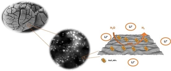
:Metal phosphides have recently emerged as promising electrocatalysts for hydrogen evolution reaction (HER). Herein, we report the synthesis of ruthenium diphosphide embedded on a dual-doped graphitic carbon by pyrolyzing chitosan beads impregnated with ruthenium chloride and phosphorus pentoxide. The as-synthesized RuP2@N-P-C displays a good electrocatalytic activity in acidic, neutral and alkaline media. We show that the HER activity of the electrocatalyst can be tuned by varying the concentration of Li+ cations. Co-diffusion effects on H+ exerted by Li+ on HER in the porous carbon matrix have been observed.
1. Introduction
With the exhaustion of fossil fuels and ongoing global warming, referring to clean and sustainable energy resources is of paramount importance [1,2]. Hydrogen (H2), a carbon-free and clean energy is regarded as an attractive energy vector for transportation and for the chemical storage of green electricity [3,4]. The current production of hydrogen by steam reforming of natural gas consumes fossil fuels and emits equivalent amounts of carbon dioxide (CO2) contributing to the greenhouse effect [5,6]. Implementation of the industrial, large scale hydrogen production by electrocatalytic water splitting with renewable electricity is set to overcome these issues as it is a carbon-zero process allowing for the production of green hydrogen [7].
To this date, Pt-based electrocatalysts constitute the most active catalysts for hydrogen evolution reaction (HER) [8]. Unfortunately, however, the towering cost and scarcity of this element is one of the bottlenecks limiting the massive production of green hydrogen [9]. Most of the studies focusing on the remarkable activity of Pt are carried out in acidic media, yet Pt-based electrocatalysts display about two orders of magnitude lowered activity in alkaline media due to sluggish kinetics [10]. Ruthenium (Ru), a relatively cheaper metal has demonstrated respectable activity in HER with minute overpotentials and extremely low on-set potentials [11,12,13] ascribed to similar metal-hydrogen bonding to that of Pt and decreased water activation barrier [14]. To boost the HER activity, a modulation of the adsorption of reaction intermediates (hydrogen) to the active sites of the electrocatalysts is necessary. For Ru-based electrocatalysts, a strong adsorption of H on Ru surface is generally observed leading to a poor HER activity [15].
As a new class of materials, metal phosphides (MPs) have recently attracted great attention as electrocatalysts for HER and organic molecule electro-oxidation reactions due to their low cost and high activities [16,17,18]. Depending on the phosphorus content, MPs exhibit different activities in HER [19]. Compared to metal (M) rich MPs, phosphorus-rich MPs possess lower conductivities due to abundant P-P bonds and M-P bonds and lower density of M-M bonds [19]. Accordingly, RuP nanoparticles demonstrated superior electrocatalytic activity compared to RuP2 due to the abundance of electrocatalytic active sites and better conductivity [20]. One of the means to enhance the conductivity of P-rich MPs is to support them on carbon materials such as graphene and activated carbons [21]. The support generally exposes more active sites and boosts the electrical conductivity facilitating electron transfer [22]. Most of the strategies used for the synthesis of RuPx supported on carbon matrices rely on the use of phosphines, or sodium hypophosphite and are generally not straightforward since several steps are needed to carry out phosphorization [23,24].
Biopolymers such as chitosan (CS) and sodium alginate have the ability to be shaped into three dimensional nanofibrillated microspheres thanks to their pH switchable solubility [25]. The hydrogels resulting from precipitation of these biopolymers in alkaline (CS) or acidic (alginic acid) aqueous solutions, when dehydrated with ethanol, can be dried using CO2 supercritical conditions and thus allow the obtainment of aerogels with a large surface area and open macroporous network [26]. Pyrolysis of aerogels has been greatly explored to prepare porous graphitic catalysts with intrinsic defects [27,28,29] on which metallic nanoparticles are grown in situ. Since CS and alginic acid based microspheres have excellent abilities to adsorb phosphates [30,31], P-doped or N,P-dual doped porous graphitic carbon could be easily synthesized through pyrolysis of biopolymers on which phosphates are adsorbed or grafted [21,32].
Recently, a phosphate ester obtained from dissolution of phosphorus pentoxide (P2O5) in methanol was revealed as an excellent precursor to prepare noncovalent phosphorylated graphene oxide and the resulting material displayed improved hole transport in polymer solar cells [33]. Inspired by this approach, we used P2O5 dissolved in ethanol as P source to grow MPs in situ during pyrolysis of metal containing CS microspheres. The strategy herein reported allows the synthesis of RuP2 nanoparticles supported in highly porous N,P-codoped graphitic carbon (RuP2@N-P-C). The electrocatalytic effect exerted by RuP2 nanoparticles embedded in nitrogen and phosphorus dual doped graphitic carbon on the hydrogen evolution reaction (HER) was studied at acidic, basic and neutral pHs using usual protocols [34,35,36,37]. In acidic media, the catalytic effect of RuP2@N-P-C was significantly increased in the presence of Li+ ions in the electrolyte. This effect, also known in literature, but of unclear explanation [38,39,40], is studied here focusing the attention on co-diffusion H+-Li+ effects based on voltammetric and electrochemical impedance spectroscopy (EIS) data.
2. Materials and Methods
2.1. Synthesis of RuP2@N-P-C
CS MMW (1000 mg; ACROS) was dissolved in 50 mL of 1.25 vol% acetic acid solution. A complete dissolution was obtained after 21 h of stirring at room temperature. CS beads were formed by dropping the solution through a 0.8 mm syringe into 4 M NaOH solution. CS beads were kept in the alkaline solution for 3 h followed by extensive washings until neutral pH. Forty-two g of the hydrogels obtained were then immersed into a 3.7 mM aqueous RuCl3 solution for 24 h. The Ru-containing alcogels were obtained by exchanging water with ethanol at increasing ethanol/water ratios (10/90; 30/70; 50/50; 70/30; 90/10; and 100% ethanol). Impregnation of Ru containing alcogels with phosphate was carried out by immersing for 24 h the alcogels in a solution of 700 mg of phosphorus pentoxide (P2O5) dissolved in 100 mL of ethanol. Dry Ru-phosphate CS aerogels were obtained using an automated CO2 critical point dryer. The aerogels were pyrolyzed under Ar atmosphere at 5 °C/min until reaching a temperature of 900 °C that was maintained for 1 h. A content of Ru and P of 6.73% and 8.93%, respectively was determined by ICP-OES by dispersing 8 mg of RuP2 @N-P-C in 8 mL of aqua regia and heating at 100 °C for 24 h to completely dissolve Ru and P.
2.2. Characterization
Chemical elemental analysis of the electrocatalyst was determined by combustion chemical analysis using a CHNS FISONS elemental analyzer. Specific surface area of RuP2@N-P-C was determined by N2 adsorption isotherms using a Micromeritics 2010 instrument. Field Emission Scanning Electron Microscopy (FESEM) images were acquired using a ZEISS ULTRA 55 microscope equipped with an X-ray detector (EDS). Scanning Transmission Electron Microscopy (STEM) images were acquired using a JEOL JEM 2100F Field Emission Transmission Electron Microscope of 200 kV equipped with an X-ray detector. X-Ray diffraction patterns were recorded using a Cubix Pro PANanalytical diffractometer. Raman spectra were recorded using a 514 nm laser excitation on a Renishaw Raman spectrophotometer equipped with a LEICA microscope. XP spectra were measured on a SPECS spectrometer using a monochromatic X-Ray source (Al and Mg) operating at 200 W.
2.3. Electrochemical Measurements
Electrochemical measurements were performed in a conventional three-electrode electrochemical cell using an Ag/AgCl (3 M NaCl) reference electrode and a Pt wire auxiliary electrode. The working electrode was a catalyst-modified glassy carbon electrode (BAS, MF 2012, geometrical area 0.071 cm2, GCE). Voltammetric and EIS experiments were carried out with a CH 660I potentiostatic device (Cambria Scientific, Llwynhendy, Llanelli, Wales, UK). EIS measurements were carried out by superimposing different bias potentials to a sinusoidal excitation of 5 mV peak-to-peak amplitude in the 0.1 to 105 Hz frequency range. Air-saturated 0.5 M H2SO4 and 1.0 M KOH aqueous solutions were used as electrolytes. The modification of the GCEs was initiated by polishing mechanically the bare GCE with 0.5 μm diamond down to 0.05 μm alumina slurry to obtain a mirror-like surface and then washed with Milli-Q water, ethanol and acetone and allowed to dry. Then, 10 μL of a suspension of the RuP2@N-P-C catalyst (5 mg·mL−1) in acetone plus nafion was dropped on the GCE and it was allowed to dry at air.
3. Results and Discussion
Synthesis and Characterization of RuP2@N-P-C
RuP2 nanoparticles embedded on graphitic porous N-P dual doped graphene were synthesized following a straightforward procedure. Briefly, an acidic chitosan (CS) solution was dropped into a concentrated NaOH solution to form CS microspheres of millimetric size. CS beads were then washed with water to neutralize the pH and the resulting hydrogels were impregnated with a RuCl3 solution. CS hydrogels were immersed in RuCl3 for 24 h, instead of dissolving CS in the metallic solution as an instantaneous gelation occurs when acetic acid is added to the CS suspension with Ru3+, thus, hindering the formation of microspheres in the subsequent steps because of the solution viscosity. Subsequently, the RuCl3/CS hydrogels were converted into alcogels by exchanging water with ethanol gradually at increasing ethanol/water ratios (from 10% to 100% ethanol). The as-obtained alcogels were then immersed for 24 h in a P2O5 solution dissolved in ethanol. Superior adsorption efficiency of phosphate ions into CS matrix is a result of electrostatic interactions of protonated groups of CS and phosphate anions [31]. Drying under supercritical CO2 conditions is in general preferred as it preserves the porosity of the beads preventing their shrinkage and collapse of their structure, thus affording light-weight and high surface area aerogels [26,41]. Scheme 1 illustrates the preparation process of the material.
We first proceeded to prepare N,P-dual doped graphitic carbon beads without the addition of metals to see the effect of P doping on the surface area. Upon pyrolysis, highly porous graphitic 3D N,P-dual doped carbons are obtained. Figure S1 shows the structure of the beads obtained upon pyrolysis of CS beads containing phosphate ions. As it can be seen, N,P-dual doped graphitic carbon (N-P-C) contains domains of large porosity similar to KOH-treated carbons obtained from pyrolysis of CS [42,43]. Adding P to CS hydrogels was found to help increase the specific surface area due to the formation of P2O5 that facilitates the gasification of carbon and distorts the graphitic structure [44]. We found that upon pyrolysis of phosphate-containing CS microspheres, the surface area increases from 241 m2∙g−1 for undoped CS beads to 817 m2∙g−1. The increase observed upon pyrolysis of the beads verifies the role of P2O5 as both a porogen agent and a dopant. Figure S2 shows the isotherm of N2 adsorption-desorption of N-P-C. Figure S3 shows the scanning transmission electron microscopy (STEM) images in bright field mode of N-P-C. The presence of holes in the layered material reveals the presence of a hierarchical porosity. To confirm the presence of the P element in the structure of N-P-C, 31P solid-state nuclear magnetic resonance (ss 31P NMR) spectroscopy was used. As it can be seen in Figure S4, the presence of a broad peak centered around −4.3 ppm reveals the presence of various polyphosphate species [32,45].
The addition of Ru results in a decrease of the surface area (765 m2∙g−1), however the P amount contained in the material increases. Incorporation of multivalent cations into CS matrix generally leads to enhanced adsorption of phosphate ions explaining the increase in P content in RuP2@N-P-C [31]. Table 1 summarizes the chemical composition of RuP2@N-P-C and N-P-C as determined by elemental analysis and inductively coupled plasma-optical emission spectroscopy (ICP-OES).
High-resolution field-emission scanning electron microscopy (HRFESEM) was used to examine the morphology of the as-obtained porous materials. As shown in Figure 1, RuP2@N-P-C beads are shaped similarly to a Bristlecone pine. At high magnifications, a fibrillated morphology is revealed (Figure 1c). Associated energy-dispersive X-ray spectroscopy (EDX) images (Figure 1d and Figure S5) reveal that Ru, P and C elements are evenly distributed on the surface.
X-Ray diffraction was used to characterize the crystal structure of RuP2@N-P-C. As displayed in the XRD pattern of RuP2@NPC (Figure S6), the peaks depicted at 23°, 30.4°, 35°, 36.1°, 38.5°, 39.2°, 46.1°, 47.1°, 47.5°, 49.9°, 50.2°, 54.9°, 56.2°, 56.9°, 59.9°, 65.1°, 68.6°, 72.1°, 73.6°, 74.5° and 76.2° correspond to the (110), (020), (012), (101), (021), (111), (022), (112), (121), (013), (211), (031), (103), (122), (113), (200), (123), (202), (024), (114) and (041) planes of the orthorhombic RuP2 phase, respectively [46,47].
Raman spectroscopy was used to assess the graphitization of the carbon obtained upon pyrolysis. Typical peaks observed around 2700, 1595 and 1354 cm−1 in the Raman spectrum of RuP2@N-P-C (Figure S7) correspond to the 2D, G and D bands, respectively. The ID/IG ratio of 0.85 found for RuP2@N-P-C indicates the formation of a graphitized carbon instead of amorphous carbon [48,49].
X-Ray Photoelectron Spectroscopy was conducted to assess the surface chemical state as well as the surface elemental composition of RuP2@NPG. XPS analysis of RuP2@NPG reveals the presence of C, Ru, N, O and P. Figure 2 shows the high resolution XPS of the different elements present in RuP2@NPG. In the C1s spectrum, the peak centered at 284.5 eV corresponds to C=C, while the ones at 285.6, 286.5 and 289.1 eV correspond to C-N/C-P, C-O and O-C=O, respectively [50,51]. Ru3d5/2 and Ru3d3/2 occur at shifted binding energies than the ones expected at 280.2 eV and 284.4 eV. The experimental N1s peak can be deconvoluted into four components at 398.2, 400.1, 401.4 and 403.7 eV which are attributed to pyridinic N, pyrrolic N, graphitic N and oxidized N, respectively [51,52,53]. The components of the P2p spectrum at 130.1, 133 and 134.2 eV correspond to P-Ru, P-C and P-O, respectively [51,54]. The latter peak might be due to the presence of residual phosphates or from oxidized P-O species resulting from incomplete P reduction or formed during air exposure [52]. In the Ru3p spectrum, the peaks centered at 462.6 and 485.1 eV correspond to Ru3p3/2 and Ru3p1/2, respectively. The peaks observed at 463.9 and 487.8 eV correspond to oxidized RuP2 species due to unavoidable air exposure [53,54]. Regarding oxygen atoms, the experimental O1s peak can be deconvoluted into two components at 531 eV and 532.5 eV which are attributed to P-O and C-O bonds, respectively [45,55].
High-resolution transmission electron microscopy (HRTEM) images reveal the layered nature of RuP2@N-P-C as well as the presence of nanoparticles of different sizes. (Figure 3a). HRTEM was used to further confirm the nature of ruthenium phosphide formed. Figure 3c evidences the presence of lattice fringes with a spacing of 0.258 nm corresponding to the (011) plane of orthorhombic RuP2 [47]. Figure S8 shows the EDX spectrum of one of the nanoparticles analyzed. It was found that the elements composing the nanoparticle are Ru and P. Dark-field STEM (DF-STEM) images (Figure S9) reveal that RuP2 nanoparticles of different sizes are evenly distributed on the N-P-C support. The average size of the nanoparticles determined by measuring a statistically relevant number of nanoparticles from HRFESEM and DF-STEM images is 8.7 nm ± 4.7 nm.
4. Electrochemistry
Figure 4 shows the negative-going linear potential scan voltammograms (LSVs) recorded at 5 mV.s−1 for GCEs modified with RuP2@N-P-C (black) and Pt/C (red) in contact with 0.50 M H2SO4 solution under stirring. One can see that the catalytic effect of HER exerted by RuP2@N-P-C, although comparable to that of 20% Pt/C, does not improve the onset potential. The Tafel analysis of the rising portion of the voltammetric wave, however, yields satisfactory values of the onset potential (−225 ± 5 vs. RHE), Tafel slope (27.1 ± 0.6 mV.decade−1), the exchange current ((1.0 ± 0.3) × 10−2 mA.cm−2), and the overpotential at a current density of 10 mA cm−2 (−300 ± 10 mV vs. RHE), when compared with other catalysts (see Table S1) in recent literature [34,35]. In contrast, in contact with 1.0 M KOH the performance of the RuP2@N-P-C- catalyst is clearly lower with that of Pt/C, as can be seen in Figure S10.
The difference in the electrocatalytic performance of RuP2@N-P-C in acidic and alkaline media can be rationalized on considering that the initial step (Volmer step) of HER in acidic media,
involves the adsorption of the generated H atom onto the surface of the catalyst active site (denoted by C* in Equation (1)) [35]. In alkaline media, the concentration of hydrogen ions is drastically diminished and the Volmer step are likely to include a water-dissociation step [36,37],
H+ aq + e− + C* → H-C*
H2O + e− + C* → H-C* + OH−aq
Accordingly, in alkaline electrolytes, the cleavage of water O–H bond and the transport of OH− from the catalyst surface to the electrolyte would be part of the limiting step in the overall HER process [38].
Similar considerations can be applied to the subsequent step in the Volmer-Heyrovsky pathway which can be represented as,
in acidic (Equation (3)) and alkaline (Equation (4)) media, respectively. In the Volmer-Tafel pathway, however, the second step
should be minimally influenced by pH changes.
H-C* + H+ aq + e− → H2 + C*
H-C* + H2O + e− → H2 + C* + OH−aq
H-C* + H-C* → H2 + C*
In this context, the importance of interfacial interactions has been emphasized [38] and the impact of alkali ions in HER at Pt and PtNi surfaces has been reported [39,40]. Accordingly, we explored the influence of Li+ ions on the catalytic activity of RuP2@N-P-C. This effect can be clearly seen under quiescent conditions, as is illustrated in Figure S11. Here, the negative-going LSVs of RuP2@N-P-C-modified GCE in contact with 0.50 M H2SO4 and 0.50 M H2SO4 + 0.15 M LiClO4 solutions are depicted. Although the voltammograms show irregular features due to the formation of H2 bubbles at relatively high overpotentials, one can see that the currents are markedly enhanced in the presence of Li+ ions in the electrolyte. Figure 5 show the Tafel plots for 0.50 M H2SO4 + 0.15 M LiClO4 and 0.50 M H2SO4 + 0.03 M LiClO4 solutions, in both cases with satisfactory linearity in the ln(j) vs. E plots.
Experimental data at different concentrations of Li+ reveal that the Tafel slope and the exchange current density increase with the concentration of alkali metal cation, whereas the onset potential remains essentially unchanged. Pertinent data can be seen in Table S1. Experiments at relatively large potential scan rates produced sigmoidal curves interrupted by the sharp transients associated to the formation of H2 bubbles over the electrode surface. This can be seen in Figure S12 where the CV of RuP2@N-P-C-modified glassy carbon electrode recorded under quiescent conditions in contact with 0.50 M H2SO4 + 0.27 M LiClO4 solution is presented. Qualitatively, the recorded CV response agrees with that theoretically described for electrocatalytic processes involving species in solution phase for large values of the rate constant k [56]:
In this equation, c denotes the concentration of the electroactive species, D its diffusion coefficient and E1/2 the half-wave potential. At sufficiently high cathodic potentials, the above equation can be simplified to [56,57]:
i.e., the current tends to a limiting value (ilim) regardless the potential scan rate. Figure S13 illustrates the variation in the limiting current and the half-wave potential with the concentration of Li+ in 0.5 M H2SO4 solutions.
Although the situation studied here involves a solid catalyst (i.e., differs from the electrocatalysis by species in solution), the above consideration can in principle be taken as a reasonable initial approximation. For our purposes, there are different aspects to emphasize:
(a) The HER process at RuP2@N-P-C, a porous material, will involve some restricted diffusion of hydrogen ions in solution through the external region of the solid in order to be adsorbed onto the different active sites. This is supported by abundant literature describing the differences observed between continuous and discrete monolayers and multilayers of catalysts such as MoS2 [58].
(b) The diffusion of different ionic species through the layers of porous catalysts can be taken as analogous to that occurring in redox polymers [59,60,61,62] in which co-diffusion effects have to be considered [63,64,65,66]. As a result, different diffusive behaviors can operate.
(c) Co-diffusion effects can be rationalized pm considering that, in solution phase, H+ and Li+ are (mainly) in the form of H3O+ and Li(H2O)n+ ions. Then, their penetration into the pores of the solid involves more or less extensive de-hydration. This process, and the subsequent ionic diffusion through the pores of the solid, could be particularly favorable for Li+. Accordingly, although H+ diffusion is faster Li+ diffusion in the electrolyte, the transport of H+ through the porous material could be facilitated by the presumably faster diffusion of Li+ in the solid.
In this scenario, two extreme diffusive behaviors can be considered for the diffusion through two phases, electrolyte and porous catalyst: full coupling and absence of coupling between phases. The first situation operates at low electrolyte concentrations and the system experiences a Cottrell-type behavior with an effective diffusion coefficient, Deff, given by:
where Dsolid, Delectrolyte, represent the diffusion coefficients of the diffusing species through the solid and the electrolyte and csolid, celectrolyte, the respective concentrations. At high electrolyte concentrations and short times (typically shorter than 10–20 ms [59,60]), the flux of the diffusing species will be the sum of the independent diffusive contributions in each phase. Then, the system will display a Cottrell-type behavior characterized by the product between an effective concentration, ceff, and the effective diffusion coefficient, Deff, given by the expression:
These situations have been studied for microparticulate films of dinuclear alkynyl-diphosphine Au(I) complexes [67] and Prussian blue [68].
The above expressions are analogue to those proposed for the co-diffusion of two electroactive species (A, B) in a unique phase [63,64,65,66]. Coupled diffusion is described by:
Here, DA, DB, represent the diffusion coefficients of the species A and B in the electrolyte and cA, cB, their respective concentrations in this phase. When no coupled diffusion occurs,
These situations have been experimentally tested for the particular case in which the A and B species are linked by an interconversion reaction [69].
A second effect on HER electrocatalysis associated to the presence of Li+ ions in the electrolyte can be considered: the co-adsorption. The effect of OH−, H2O and cations co-adsorption on Pt surfaces has been studied with regard of HER [70,71,72]. Here, a variety of factors have been balanced (formation of adducts, destabilization of OHads, partial charge retention, etc.), but further research is needed to achieve a complete view of this matter [38].
Qualitatively, these approaches can be applied to explain the accelerating effect of Li+ ions on HER at porous catalysts. Focusing our attention to the diffusive effects, and at the expense of the development of a detailed theoretical model, it is pertinent to note that if no coupling diffusion of H+ and Li+ ions occurs, no influence of Li+ on the HER process should take place. If coupled diffusion occurs, and if the diffusion of Li+ is faster than that of H+ through the porous film, the effect of Li+ would be the increase in the effective (co)diffusion of the system. Assuming that co-diffusion is operative, Equations (6) and (7) can be approximated by:
where DH+, DLi+ are the diffusion coefficients of H+ and Li+ and cH+, cLi+ their respective concentrations in the electrolyte. Then, in experiments performed varying the concentration of Li+ at a constant concentration of hydrogen ions such as in Figure S13, taking iºlim = nFADH+1/2cH+k1/2, we obtain,
At large Li+ concentrations, Equation (14) tends to a linear variation in f(ilim) on the square root of the concentration of Li+ in the electrolyte. Figure 6 shows the variation in the f(ilim) ratio with the square root of the Li+ concentration resulting from voltammetric data such as depicted in Figure S12. One can see that the values at high Li+ concentrations can reasonably be fitted to a straight line. The slope of the linear plot (2.30 ± 0.05) permits to evaluate a (DLi+/DH+)1/2 ratio of 4.6. This result implies that the diffusion is faster for Li+ than for H+, an effect that can be understood assuming that the rate-determining step of the diffusional process is that occurring through the porous phosphide material. In short, this means that the porous material can accommodate more efficiently Li+ ions than adsorb hydrogen ions. At this stage, our results suggest that, despite the approximate character of the previous theoretical considerations, at least a part of the contribution of Li+ ions to promote HER at RuP2@N-P-C-modified GCEs can be attributed to co-diffusion effects. A more detailed understanding of Li+ effect obviously requires further research to elucidate influence of adsorption and ion trapping processes.
EIS data were consistent with the foregoing set of considerations. When bias potentials separated from the proton discharge are applied, light differences were obtained RuP2@N-P-C-modified GCEs immersed into 0.50 M H2SO4 and 0.50 M H2SO4 + 0.14 M LiClO4 solutions (Figure 7 and Supplementary Information, Figure S14). However, when the bias potential approaches those where the HER starts, the presence of Li+ ions in the electrolyte determines a decrease in the total impedance values at low frequencies. The Nyquist plots show two overlapping capacitive loops which can be fitted to the equivalent circuit shown in Figure S15. Remarkably, the negative increase in the bias potential does not alter significantly the high-frequency loop but determines important changes in the low-frequency region where the capacitive effects tend to vanish on increasing the hydrogen evolution. The charge transfer resistance values significantly decrease, and this decrease is larger as the Li+ concentration is, as can be seen in Figure S16 of supplementary Information for different bias potentials.
5. Conclusions
In this contribution, simultaneous P-doping and growth of crystalline ruthenium diphosphide was achieved through a straightforward approach consisting on the pyrolysis of Ru3+-CS beads on which phosphate anions were previously co-adsorbed. Upon pyrolysis, highly porous N,P-dual-doped defective graphitic carbon on which crystalline RuP2 nanoparticles are embedded was obtained. RuP2@N-P-C films deposited onto GCEs exert an electrocatalytic effect on HER in acidic media. This effect is significantly increased upon addition of Li+ ions to the electrolyte. Voltammetric experiments at variable concentrations of this alkali cation suggest that co-diffusion effects, Li+ diffusing faster than hydrogen ions through the porous catalyst can be responsible, at least partially, for this effect. The sustainable procedure proposed could be applied to prepare other non-precious metal phosphides supported on dual-doped highly porous graphitic carbons. Future studies should rely on the use of in situ/operando techniques [73] to further elucidate the dynamic changes occurring in the electrocatalysts during HER.
Supplementary Materials
The following supporting information can be downloaded at: https://www.mdpi.com/article/10.3390/nano12203597/s1, Figure S1. FESEM images of N,P-dual doped porous graphitic carbon (N-P-C). Figure S2. N2 adsorption-desorption isotherm of N-P-C. Figure S3. Bright Field STEM images of N-P-C. Figure S4. 31P SS NMR spectrum of N-P-C. Figure S5. FESEM image and associated EDX mapping of RuP2@N-P-C. Figure S6. XRD pattern of RuP2@N-P-C. Figure S7. Raman spectrum of RuP2@N-P-C. Figure S8. EDX spectrum of RuP2@N-P-C. Figure S9. Dark-field STEM images of RuP2@N-P-C. Figure S10. Negative-going LSVs of RuP2@N-P-C (red) and Pt/C-modified (black) glassy carbon electrodes under stirring conditions (650 rpm) in contact with 1.0 M KOH. Potential scan rate 5 mV.s−1. Figure S11. Negative-going LSVs of RuP2@N-P-C modified GCE in contact with 0.50 M H2SO4 (red) and 0.50 M H2SO4 + 0.15 M LiClO4 under quiescent conditions. Potential scan rate 2 mV.s−1. Figure S12. CV of RuP2@N-P-C-modified glassy carbon electrode recorded under quiescent conditions in contact with 0.50 M H2SO4 + 0.27 M LiClO4 solution. Potential scan initiated at 0.30 V vs. RHE in the negative direction; potential scan rate 50 mV.s−1. The arrows mark the ascending (initial cathodic scan) and descending (subsequent positive-going scan) branches of the CV. Figure S13. Variation in: (a) the limiting current and (b) the half-wave potential with the concentration of Li+ in CVs at RuP2@N-P-C-modified GCEs recorded under quiescent conditions in contact with 0.50 M H2SO4 + LiClO4 solutions. Potential scan initiated at 0.30 V vs. RHE in the negative direction; potential scan rate 50 mV.s−1. Figure S14. Nyquist plots of RuP2@N-P-C-modified GCEs recorded under quiescent conditions in contact with 0.50 M H2SO4 and 0.50 M H2SO4 + 0.14 M LiClO4 solutions. Bias potential 0.40 V vs. RHE. The inset shows the magnified view of the high frequency region. Figure S15. Nyquist plots of RuP2@N-P-C-modified GCEs recorded under quiescent conditions in contact with a) 0.50 M H2SO4 and b) 0.50 M H2SO4 + 0.14 M LiClO4 solutions. Bias potential 0.20 V vs. RHE. Experimental data points (black circles) are superimposed to the theoretical impedance spectra (continuous lines) based on the fit of experimental data to the equivalent circuit in c). This equivalent circuit contains the solution resistance (Rs) in series with two parallel RC units, the first one contains the charge transfer resistance (Rct) and the double-layer capacitance (Cdl); the second can be associated to the porous RuP2@N-P-C modifier. Its impedance is constituted by a porous resistance (Rpor) and a non-ideal capacitance element, represented by a constant phase element (Qpor). Table S1. Comparison of the catalytic parameters of RuP2@N-P-C with other HER catalysts. Figure S16. Variation in the Rpor determined after fitting the experimental impedance spectra recorded at RuP2@N-P-C-modified GCEs in contact with 0.50 M H2SO4 plus LiClO4 solutions with the Li+ concentration at different bias potentials.
Author Contributions
Conceptualization, A.A., A.D.-C. and H.G.; methodology, A.A. and A.D.-C.; software, A.A. and A.D.-C.; validation, A.D.-C. and H.G.; formal analysis, A.A. and A.D.-C.; investigation, A.A. and A.D.-C.; resources, A.D.-C. and H.G.; data curation, A.A. and A.D.-C.; writing—original draft preparation, A.A. and A.D.-C.; writing—review and editing, A.A., A.D.-C. and H.G.; supervision, A.D.-C. and H.G.; funding acquisition, A.D.-C. and H.G. All authors have read and agreed to the published version of the manuscript.
Funding
Financial support by the Spanish Ministry of Science and Innovation (PDI2022- 126071OB-C21 and Severo Ochoa) and the Generalitat Valenciana (Prometeo 2021-038) are gratefully acknowledged. A.A. thanks assistance from Erasmus+ for partial support of her stay at Valencia. The European Commission is acknowledged for partial funding through the ECO2Fuel project.
Data Availability Statement
Not applicable.
Acknowledgments
UEMF is acknowledged for financial support. A.A. thanks UEMF and UPV for an Erasmus+ 2019-1-ES01-KA107-062073 Scholarship.
Conflicts of Interest
The authors declare no conflict of interest. The funders had no role in the design of the study; in the collection, analyses, or interpretation of data; in the writing of the manuscript; or in the decision to publish the results.
References
- McGlade, C.; Ekins, P. The geographical distribution of fossil fuels unused when limiting global warming to 2 °C. Nature 2015, 517, 187–190. [Google Scholar] [CrossRef] [PubMed] [Green Version]
- Welsby, D.; Price, J.; Pye, S.; Ekins, P. Unextractable fossil fuels in a 1.5 °C world. Nature 2021, 597, 230–234. [Google Scholar] [CrossRef] [PubMed]
- Hosseini, S.E.; Wahid, M.A. Hydrogen production from renewable and sustainable energy resources: Promising green energy carrier for clean development. Renew. Sustain. Energy Rev. 2016, 57, 850–866. [Google Scholar] [CrossRef]
- Turner, J.A. Sustainable Hydrogen Production. Science 2004, 305, 972–974. [Google Scholar] [CrossRef] [PubMed]
- Boretti, A.; Banik, B.K. Advances in Hydrogen Production from Natural Gas Reforming. Adv. Sustain. Syst. 2021, 2, 2100097. [Google Scholar] [CrossRef]
- LeValley, T.L.; Richard, A.R.; Fan, M. The progress in water gas shift and steam reforming hydrogen production technologies—A review. Int. J. Hydrog. Energy 2014, 39, 16983–17000. [Google Scholar] [CrossRef]
- Wang, S.; Lu, A.; Zhong, C.-J. Hydrogen production from water electrolysis: Role of catalysts. Nano Converg. 2021, 8, 4. [Google Scholar] [CrossRef]
- Tiwari, J.N.; Sultan, S.; Myung, C.W.; Yoon, T.; Li, N.; Ha, M.; Harzandi, A.M.; Park, H.J.; Kim, D.Y.; Chandrasekaran, S.S.; et al. Multicomponent electrocatalyst with ultralow Pt loading and high hydrogen evolution activity. Nat. Energy 2018, 3, 773–782. [Google Scholar] [CrossRef]
- Zou, X.; Zhang, Y. Noble metal-free hydrogen evolution catalysts for water splitting. Chem. Soc. Rev. 2015, 44, 5148–5180. [Google Scholar] [CrossRef]
- Mahmood, N.; Yao, Y.; Zhang, J.-W.; Pan, L.; Zhang, X.; Zou, J.-J. Electrocatalysts for Hydrogen Evolution in Alkaline Electrolytes: Mechanisms, Challenges, and Prospective Solutions. Adv. Sci. 2018, 5, 1700464. [Google Scholar] [CrossRef]
- Mahmood, J.; Li, F.; Jung, S.-M.; Okyay, M.S.; Ahmad, I.; Kim, S.-J.; Park, N.; Jeong, H.Y.; Baek, J.-B. An efficient and pH-universal ruthenium-based catalyst for the hydrogen evolution reaction. Nat. Nanotechnol. 2017, 12, 441–446. [Google Scholar] [CrossRef]
- Tiwari, J.N.; Harzandi, A.M.; Ha, M.; Sultan, S.; Myung, C.W.; Park, H.J.; Kim, D.Y.; Thangavel, P.; Singh, A.N.; Sharma, P.; et al. High-Performance Hydrogen Evolution by Ru Single Atoms and Nitrided-Ru Nanoparticles Implanted on N-Doped Graphitic Sheet. Adv. Energy Mater. 2019, 9, 1900931. [Google Scholar] [CrossRef]
- Tiwari, J.N.; Dang, N.K.; Sultan, S.; Thangavel, P.; Jeong, H.Y.; Kim, K.S. Multi-heteroatom-doped carbon from waste-yeast biomass for sustained water splitting. Nat. Sustain. 2020, 3, 556–563. [Google Scholar] [CrossRef]
- Bae, S.-Y.; Mahmood, J.; Jeon, I.-Y.; Baek, J.-B. Recent advances in ruthenium-based electrocatalysts for the hydrogen evolution reaction. Nanoscale Horiz. 2020, 5, 43–56. [Google Scholar] [CrossRef]
- Yang, Y.; Wu, D.; Yu, Y.; Li, J.; Rao, P.; Jia, C.; Liu, Z.; Chen, Q.; Huang, W.; Luo, J.; et al. Bridge the activity and durability of Ruthenium for hydrogen evolution reaction with the RuOC link. Chem. Eng. J. 2022, 433, 134421. [Google Scholar] [CrossRef]
- Shi, Y.; Zhang, B. Recent advances in transition metal phosphide nanomaterials: Synthesis and applications in hydrogen evolution reaction. Chem. Soc. Rev. 2016, 45, 1529–1541. [Google Scholar] [CrossRef]
- Tiwari, J.N.; Dang, N.K.; Park, H.J.; Sultan, S.; Kim, M.G.; Haiyan, J.; Lee, Z.; Kim, K.S. Remarkably enhanced catalytic activity by the synergistic effect of palladium single atoms and palladium–cobalt phosphide nanoparticles. Nano Energy 2020, 78, 105166. [Google Scholar] [CrossRef]
- Yu, Z.; Wei, X.-K.; Xu, J.; Li, Y.; Araujo, A.; Faria, J.L.; Dunin-Borkowski, R.E.; Liu, L. Multifunctional Noble Metal Phosphide Electrocatalysts for Organic Molecule Electro-Oxidation. ACS Appl. Energy Mater. 2021, 4, 1593–1600. [Google Scholar] [CrossRef]
- Zhao, X.; Kong, X.; Liu, Z.; Li, Z.; Xie, Z.; Wu, Z.; He, F.; Chang, X.; Yang, P.; Zheng, J.; et al. The cutting-edge phosphorus-rich metal phosphides for energy storage and conversion. Nano Today 2021, 40, 101245. [Google Scholar] [CrossRef]
- Chang, Q.; Ma, J.; Zhu, Y.; Li, Z.; Xu, D.; Duan, X.; Peng, W.; Li, Y.; Zhang, G.; Zhang, F.; et al. Controllable Synthesis of Ruthenium Phosphides (RuP and RuP2) for pH-Universal Hydrogen Evolution Reaction. ACS Sustain. Chem. Eng. 2018, 6, 6388–6394. [Google Scholar] [CrossRef]
- Wang, J.; Kong, H.; Zhang, J.; Hao, Y.; Shao, Z.; Ciucci, F. Carbon-based electrocatalysts for sustainable energy applications. Prog. Mater. Sci. 2021, 116, 100717. [Google Scholar] [CrossRef]
- Kweon, D.H.; Okyay, M.S.; Kim, S.-J.; Jeon, J.-P.; Noh, H.-J.; Park, N.; Mahmood, J.; Baek, J.-B. Ruthenium anchored on carbon nanotube electrocatalyst for hydrogen production with enhanced Faradaic efficiency. Nat. Commun. 2020, 11, 1278. [Google Scholar] [CrossRef] [Green Version]
- Liu, T.; Wang, S.; Zhang, Q.; Chen, L.; Hu, W.; Li, C.M. Ultrasmall Ru2P nanoparticles on graphene: A highly efficient hydrogen evolution reaction electrocatalyst in both acidic and alkaline media. Chem. Commun. 2018, 54, 3343–3346. [Google Scholar] [CrossRef] [PubMed]
- Teller, H.; Krichevski, O.; Gur, M.; Gedanken, A.; Schechter, A. Ruthenium Phosphide Synthesis and Electroactivity toward Oxygen Reduction in Acid Solutions. ACS Catal. 2015, 5, 4260–4267. [Google Scholar] [CrossRef]
- El Kadib, A. Chitosan as a Sustainable Organocatalyst: A Concise Overview. ChemSusChem 2015, 8, 217–244. [Google Scholar] [CrossRef] [PubMed]
- El Kadib, A. Green and Functional Aerogels by Macromolecular and Textural Engineering of Chitosan Microspheres. Chem. Rec. 2020, 20, 753–772. [Google Scholar] [CrossRef]
- Primo, A.; Sánchez, E.; Delgado, J.M.; García, H. High-yield production of N-doped graphitic platelets by aqueous exfoliation of pyrolyzed chitosan. Carbon 2014, 68, 777–783. [Google Scholar] [CrossRef]
- Anouar, A.; Ramírez Grau, R.; Katir, N.; Franconetti, A.; El Kadib, A.; Primo, A.; García, H. Nanometer-thick defective graphene films decorated with oriented ruthenium nanoparticles. Higher activity of 101 vs 002 plane for silane-alcohol coupling and hydrogen transfer reduction. J. Catal. 2022, 407, 342–352. [Google Scholar] [CrossRef]
- Wang, J.; Kim, J.; Choi, S.; Wang, H.; Lim, J. A Review of Carbon-Supported Nonprecious Metals as Energy-Related Electrocatalysts. Small Methods 2020, 4, 2000621. [Google Scholar] [CrossRef]
- Liu, X.; Zhang, L. Removal of phosphate anions using the modified chitosan beads: Adsorption kinetic, isotherm and mechanism studies. Powder Technol. 2015, 277, 112–119. [Google Scholar] [CrossRef]
- Eltaweil, A.S.; Omer, A.M.; El-Aqapa, H.G.; Gaber, N.M.; Attia, N.F.; El-Subruiti, G.M.; Mohy-Eldin, M.S.; Abd El-Monaem, E.M. Chitosan based adsorbents for the removal of phosphate and nitrate: A critical review. Carbohydr. Polym. 2021, 274, 118671. [Google Scholar] [CrossRef] [PubMed]
- Anouar, A.; Grirrane, A.; Álvarez, E.; Katir, N.; Primo, A.; Garcia, H.; El Kadib, A. Nanosized copper stabilized on ternary P, N, S-doped graphene from chitosan shellfish waste: Preparation and catalysis of single and double A3-type amine coupling. Mater. Today Sustain. 2022, 18, 100109. [Google Scholar] [CrossRef]
- Chen, X.; Liu, Q.; Zhang, M.; Ju, H.; Zhu, J.; Qiao, Q.; Wang, M.; Yang, S. Noncovalent phosphorylation of graphene oxide with improved hole transport in high-efficiency polymer solar cells. Nanoscale 2018, 10, 14840–14846. [Google Scholar] [CrossRef]
- Gao, M.-R.; Liang, J.-X.; Zheng, Y.-R.; Xu, Y.-F.; Jiang, J.; Gao, Q.; Li, J.; Yu, S.-H. An efficient molybdenum disulfide/cobalt diselenide hybrid catalyst for electrochemical hydrogen generation. Nat. Commun. 2015, 6, 5982. [Google Scholar] [CrossRef] [Green Version]
- Ding, Q.; Song, B.; Xu, P.; Jin, S. Efficient Electrocatalytic and Photoelectrochemical Hydrogen Generation Using MoS2 and Related Compounds. Chem 2016, 1, 699–726. [Google Scholar] [CrossRef] [Green Version]
- Zheng, Y.; Jiao, Y.; Vasileff, A.; Qiao, S.-Z. The Hydrogen Evolution Reaction in Alkaline Solution: From Theory, Single Crystal Models, to Practical Electrocatalysts. Angew. Chem. Int. Ed. 2018, 57, 7568–7579. [Google Scholar] [CrossRef] [PubMed]
- Subbaraman, R.; Tripkovic, D.; Strmcnik, D.; Chang, K.-C.; Uchimura, M.; Paulikas, A.P.; Stamenkovic, V.; Markovic, N.M. Enhancing Hydrogen Evolution Activity in Water Splitting by Tailoring Li+-Ni(OH)2-Pt Interfaces. Science 2011, 334, 1256–1260. [Google Scholar] [CrossRef]
- Dubouis, N.; Grimaud, A. The hydrogen evolution reaction: From material to interfacial descriptors. Chem. Sci. 2019, 10, 9165–9181. [Google Scholar] [CrossRef] [Green Version]
- Liu, E.; Li, J.; Jiao, L.; Doan, H.T.T.; Liu, Z.; Zhao, Z.; Huang, Y.; Abraham, K.M.; Mukerjee, S.; Jia, Q. Unifying the Hydrogen Evolution and Oxidation Reactions Kinetics in Base by Identifying the Catalytic Roles of Hydroxyl-Water-Cation Adducts. J. Am. Chem. Soc. 2019, 141, 3232–3239. [Google Scholar] [CrossRef]
- Weber, D.J.; Janssen, M.; Oezaslan, M. Effect of Monovalent Cations on the HOR/HER Activity for Pt in Alkaline Environment. J. Electrochem. Soc. 2019, 166, F66–F73. [Google Scholar] [CrossRef]
- Anouar, A.; Katir, N.; El Kadib, A.; Primo, A.; García, H. Palladium Supported on Porous Chitosan–Graphene Oxide Aerogels as Highly Efficient Catalysts for Hydrogen Generation from Formate. Molecules 2019, 24, 3290. [Google Scholar] [CrossRef] [PubMed] [Green Version]
- Primo, A.; Forneli, A.; Corma, A.; García, H. From Biomass Wastes to Highly Efficient CO2 Adsorbents: Graphitisation of Chitosan and Alginate Biopolymers. ChemSusChem 2012, 5, 2207–2214. [Google Scholar] [CrossRef] [PubMed]
- Zhu, Y.-P.; Liu, Y.; Liu, Y.-P.; Ren, T.-Z.; Chen, T.; Yuan, Z.-Y. Direct Synthesis of Phosphorus-Doped Mesoporous Carbon Materials for Efficient Electrocatalytic Oxygen Reduction. ChemCatChem 2015, 7, 2903–2909. [Google Scholar] [CrossRef]
- Liu, G.; Liu, Z.; Li, J.; Zeng, M.; Li, Z.; He, L.; Li, F. Chitosan/phytic acid hydrogel as a platform for facile synthesis of heteroatom-doped porous carbon frameworks for electrocatalytic oxygen reduction. Carbon 2018, 137, 68–77. [Google Scholar] [CrossRef]
- Anouar, A.; Katir, N.; Mamede, A.-S.; Aboulaich, A.; Draoui, K.; Royer, S.; El Kadib, A. Synthesis and multifaceted use of phosphorylated graphene oxide: Growth of titanium dioxide clusters, interplay with gold nanoparticles and exfoliated sheets in bioplastics. Mater. Chem. Front. 2019, 3, 242–250. [Google Scholar] [CrossRef]
- Pu, Z.; Amiinu, I.S.; Kou, Z.; Li, W.; Mu, S. RuP2-Based Catalysts with Platinum-like Activity and Higher Durability for the Hydrogen Evolution Reaction at All pH Values. Angew. Chem. Int. Ed. 2017, 56, 11559–11564. [Google Scholar] [CrossRef]
- Guo, Z.; Li, J.; Qi, H.; Sun, X.; Li, H.; Tamirat, A.G.; Liu, J.; Wang, Y.; Wang, L. A Highly Reversible Long-Life Li–CO2 Battery with a RuP2-Based Catalytic Cathode. Small 2019, 15, 1803246. [Google Scholar] [CrossRef]
- He, J.; Anouar, A.; Primo, A.; García, H. Quality Improvement of Few-Layers Defective Graphene from Biomass and Application for H2 Generation. Nanomaterials 2019, 9, 895. [Google Scholar] [CrossRef] [Green Version]
- Wang, J.; Gao, Y.; You, T.L.; Ciucci, F. Bimetal-decorated nanocarbon as a superior electrocatalyst for overall water splitting. J. Power Sources 2018, 401, 312–321. [Google Scholar] [CrossRef]
- Wu, H.; Geng, J.; Ge, H.; Guo, Z.; Wang, Y.; Zheng, G. Egg-Derived Mesoporous Carbon Microspheres as Bifunctional Oxygen Evolution and Oxygen Reduction Electrocatalysts. Adv. Energy Mater. 2016, 6, 1600794. [Google Scholar] [CrossRef]
- Wang, J.; Ciucci, F. In-situ synthesis of bimetallic phosphide with carbon tubes as an active electrocatalyst for oxygen evolution reaction. Appl. Catal. B 2019, 254, 292–299. [Google Scholar] [CrossRef]
- Pu, Z.; Zhao, J.; Amiinu, I.S.; Li, W.; Wang, M.; He, D.; Mu, S. A universal synthesis strategy for P-rich noble metal diphosphide-based electrocatalysts for the hydrogen evolution reaction. Energy Environ. Sci. 2019, 12, 952–957. [Google Scholar] [CrossRef]
- Zhou, F.; Sa, R.; Zhang, X.; Zhang, S.; Wen, Z.; Wang, R. Robust ruthenium diphosphide nanoparticles for pH-universal hydrogen evolution reaction with platinum-like activity. Appl. Catal. B 2020, 274, 119092. [Google Scholar] [CrossRef]
- Luo, Q.; Xu, C.; Chen, Q.; Wu, J.; Wang, Y.; Zhang, Y.; Fan, G. Synthesis of ultrafine ruthenium phosphide nanoparticles and nitrogen/phosphorus dual-doped carbon hybrids as advanced electrocatalysts for all-pH hydrogen evolution reaction. Int. J. Hydrog. Energy 2019, 44, 25632–25641. [Google Scholar] [CrossRef]
- Li, Y.; Li, S.; Wang, Y.; Wang, J.; Liu, H.; Liu, X.; Wang, L.; Liu, X.; Xue, W.; Ma, N. Electrochemical synthesis of phosphorus-doped graphene quantum dots for free radical scavenging. Phys. Chem. Chem. Phys. 2017, 19, 11631–11638. [Google Scholar] [CrossRef]
- Nicholson, R.S.; Shain, I. Theory of Stationary Electrode Polarography -Single Scan and Cyclic Methods Applied to Reversible, Irreversible, and Kinetic Systems. Anal. Chem. 1964, 36, 706–723. [Google Scholar] [CrossRef]
- SavÉAnt, J.M.; Vianello, E. Recherches sur les courants catalytiques en polarographie—Oscillographique à balayage linéaire de tension. Etude Théorique. In Advances in Polarography; Longmuir, I.S., Ed.; Pergamon: Oxford, UK, 1960; pp. 367–374. [Google Scholar]
- Li, G.; Zhang, D.; Qiao, Q.; Yu, Y.; Peterson, D.; Zafar, A.; Kumar, R.; Curtarolo, S.; Hunte, F.; Shannon, S.; et al. All The Catalytic Active Sites of MoS2 for Hydrogen Evolution. J. Am. Chem. Soc. 2016, 138, 16632–16638. [Google Scholar] [CrossRef]
- Andrieux, C.P.; Hapiot, P.; Savéant, J.M. Electron-transfer coupling of diffusional pathways: Theory for potential step chronoamperometry and chronocoulometry. J. Electroanal. Chem. Interf. Electrochem. 1984, 172, 49–65. [Google Scholar] [CrossRef]
- Miller, C.J.; Majda, M. Microporous aluminum oxide films at electrodes part II. studies of electron transport in the Al2O3 matrix derivatized by adsorption of poly(4-vinylpyridine). J. Electroanal. Chem. Interf. Electrochem. 1986, 207, 49–72. [Google Scholar] [CrossRef]
- Miller, C.J.; Majda, M. Microporous aluminum oxide films at electrodes. Dynamics of ascorbic acid oxidation mediated by ferricyanide ions bound electrostatically in bilayer assemblies of octadecyltrichlorosilane and an octadecylviologen amphiphile. Anal. Chem. 1988, 60, 1168–1176. [Google Scholar] [CrossRef]
- Guidelli, R.; Cozzi, D. Homogeneous chemical equilibria in polarography. II. Examples. J. Phys. Chem. 1967, 71, 3027–3034. [Google Scholar] [CrossRef]
- De Jong, H.G.; Van Leeuwen, H.P.; Holub, K. Voltammetry of metal complex systems with different diffusion coefficients of the species involved: Part I. Analytical approaches to the limiting current for the general case including association/dissociation kinetics. J. Electroanal. Chem. Interf. Electrochem. 1987, 234, 1–16. [Google Scholar] [CrossRef]
- Evans, D.H. Multicomponent diffusion with chemical reactions and its effect in voltammetry. J. Electroanal. Chem. Interf. Electrochem. 1989, 258, 451–456. [Google Scholar] [CrossRef]
- Blauch, D.N.; Anson, F.C. Effects of interconversion and electron transfer on voltammetric responses for two-component systems with differing diffusion coefficients. J. Electroanal. Chem. Interf. Electrochem. 1991, 309, 313–318. [Google Scholar] [CrossRef]
- Oldham, K.B. Steady-state microelectrode voltammetry as a route to homogeneous kinetics. J. Electroanal. Chem. Interf. Electrochem. 1991, 313, 3–16. [Google Scholar] [CrossRef]
- Doménech-Carbó, A.; Koshevoy, I.O.; Montoya, N.; Pakkanen, T.A.; Doménech-Carbó, M.T. Solvent-Independent Electrode Potentials of Solids Undergoing Insertion Electrochemical Reactions: Part II. Experimental Data for Alkynyl–diphosphine Dinuclear Au(I) Complexes Undergoing Electron Exchange Coupled to Anion Exchange. J. Phys. Chem. C 2012, 116, 25984–25992. [Google Scholar] [CrossRef]
- Doménech-Carbó, A.; Scholz, F.; Montoya, N. Solvent-Independent Electrode Potentials of Solids Undergoing Insertion Electrochemical Reactions: Part III. Experimental Data for Prussian Blue Undergoing Electron Exchange Coupled to Cation Exchange. J. Phys. Chem. C 2012, 116, 25993–25999. [Google Scholar] [CrossRef]
- Doménech, A.; García-España, E.; Navarro, P.; Reviriego, F. Electrochemical determination of the stability of complexes formed by proton-ionizable ligands of 3,5-disubstituted 1H-pyrazole with phenethylamine. Talanta 2000, 51, 625–636. [Google Scholar] [CrossRef]
- van der Niet, M.J.T.C.; Garcia-Araez, N.; Hernández, J.; Feliu, J.M.; Koper, M.T.M. Water dissociation on well-defined platinum surfaces: The electrochemical perspective. Catal. Today 2013, 202, 105–113. [Google Scholar] [CrossRef]
- McCrum, I.T.; Janik, M.J. pH and Alkali Cation Effects on the Pt Cyclic Voltammogram Explained Using Density Functional Theory. J. Phys. Chem. C 2016, 120, 457–471. [Google Scholar] [CrossRef]
- Chen, X.; McCrum, I.T.; Schwarz, K.A.; Janik, M.J.; Koper, M.T.M. Co-adsorption of Cations as the Cause of the Apparent pH Dependence of Hydrogen Adsorption on a Stepped Platinum Single-Crystal Electrode. Angew. Chem. Int. Ed. 2017, 56, 15025–15029. [Google Scholar] [CrossRef] [PubMed]
- Wang, J.; Gao, Y.; Kong, H.; Kim, J.; Choi, S.; Ciucci, F.; Hao, Y.; Yang, S.; Shao, Z.; Lim, J. Non-precious-metal catalysts for alkaline water electrolysis: Operando characterizations, theoretical calculations, and recent advances. Chem. Soc. Rev. 2020, 49, 9154–9196. [Google Scholar] [CrossRef] [PubMed]
Scheme 1.
Schematic illustration of the synthesis of RuP2@NPC, (i) impregnation of CS hydrogels with RuCl3 solution; (ii) impregnation of Ru containing CS beads with P2O5; (iii) supercritical drying of CS-Ru-Phosphate beads and (iv) pyrolysis at 900 °C under inert atmosphere.
Scheme 1.
Schematic illustration of the synthesis of RuP2@NPC, (i) impregnation of CS hydrogels with RuCl3 solution; (ii) impregnation of Ru containing CS beads with P2O5; (iii) supercritical drying of CS-Ru-Phosphate beads and (iv) pyrolysis at 900 °C under inert atmosphere.

Figure 1.
FESEM images (a–c) of RuP2@N-P-C at different magnifications and EDS layered image (d) showing the even distribution of C, Ru and P elements.
Figure 1.
FESEM images (a–c) of RuP2@N-P-C at different magnifications and EDS layered image (d) showing the even distribution of C, Ru and P elements.
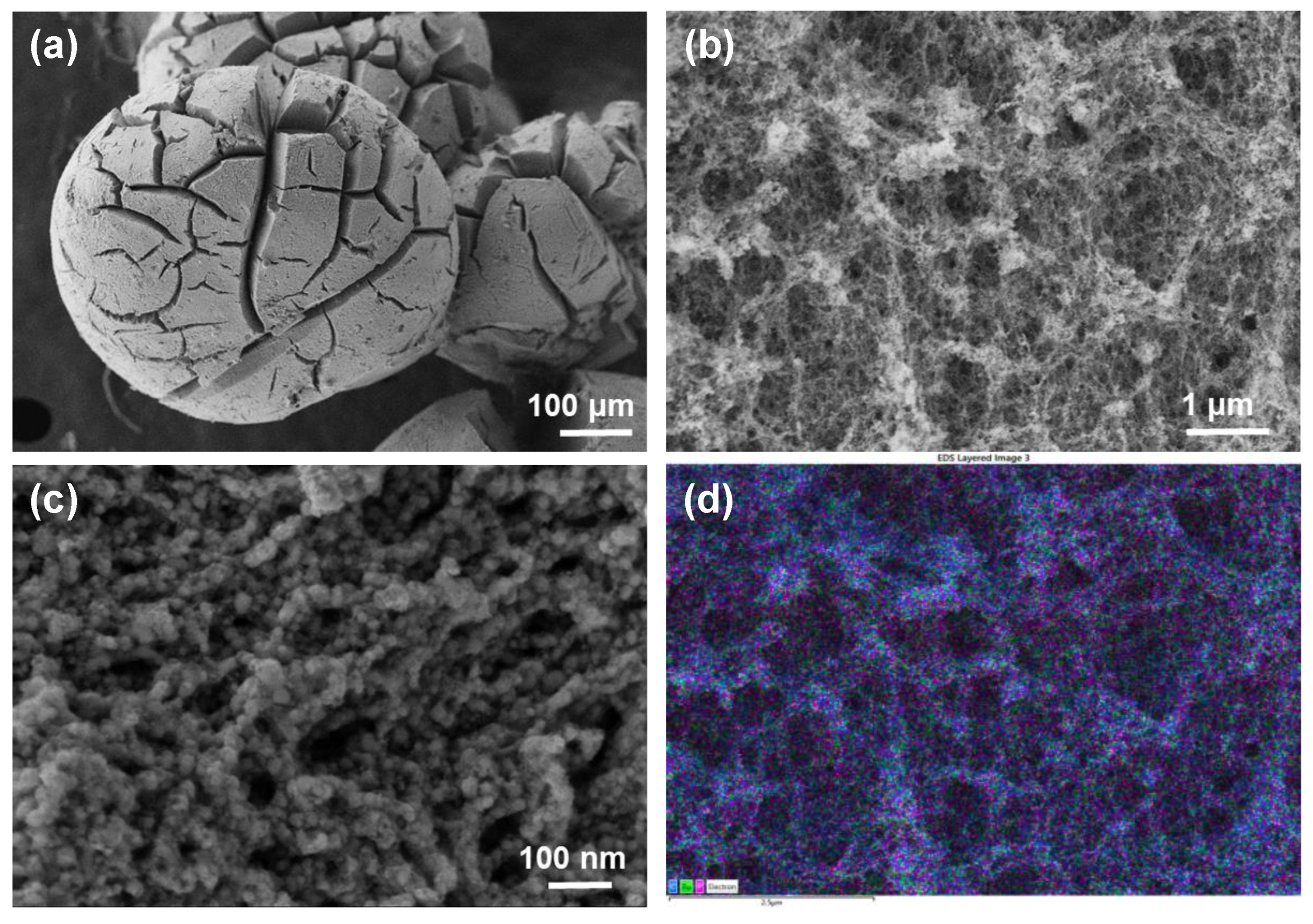
Figure 2.
(a) XPS survey spectrum of RuP2@N-P-C. High-resolution XPS spectra of (b) C 1s, (c) N 1s, (d) P 2p and (e) Ru 3p and (f) O 1s.
Figure 2.
(a) XPS survey spectrum of RuP2@N-P-C. High-resolution XPS spectra of (b) C 1s, (c) N 1s, (d) P 2p and (e) Ru 3p and (f) O 1s.

Figure 3.
(a–c) HRTEM images of RuP2@N-P-C at different magnifications. The inset in the image (b) corresponds to the FFT spectrum of the electron diffraction from one RuP2 nanoparticle supported on N-P-C.
Figure 3.
(a–c) HRTEM images of RuP2@N-P-C at different magnifications. The inset in the image (b) corresponds to the FFT spectrum of the electron diffraction from one RuP2 nanoparticle supported on N-P-C.
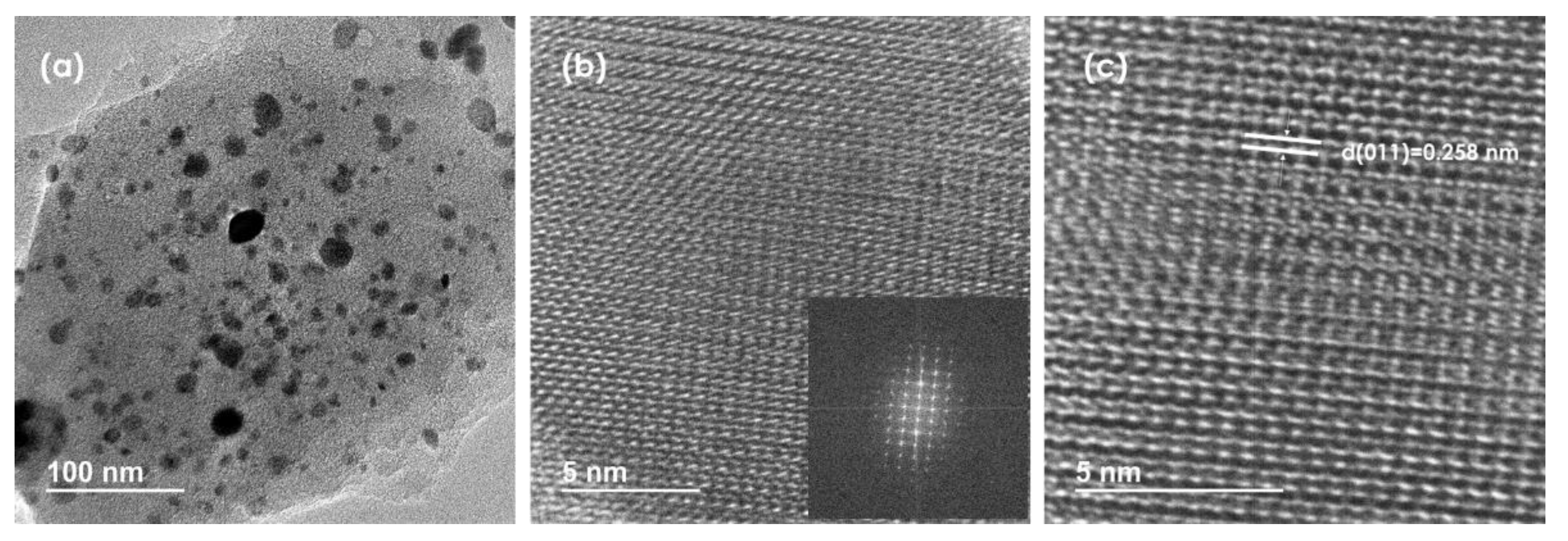
Figure 4.
Negative-going LSVs of RuP2@N-P-C- (black) and Pt/C-modified (red) glassy carbon electrodes under stirring conditions (650 rpm) in contact with 0.50 M H2SO4. Potential scan rate 5 mV.s−1.
Figure 4.
Negative-going LSVs of RuP2@N-P-C- (black) and Pt/C-modified (red) glassy carbon electrodes under stirring conditions (650 rpm) in contact with 0.50 M H2SO4. Potential scan rate 5 mV.s−1.

Figure 5.
Tafel plots from the foot of the voltammetric curves recorded at RuP2@N-P-C-modified GCEs immersed into 0.50 M H2SO4 + 0.15 M LiClO4 (solid circles) and 0.50 M H2SO4 + 0.03 M LiClO4 solutions (circles). Potential scan rate 2 mV.s−1. Averaged values from three replicate measurements.
Figure 5.
Tafel plots from the foot of the voltammetric curves recorded at RuP2@N-P-C-modified GCEs immersed into 0.50 M H2SO4 + 0.15 M LiClO4 (solid circles) and 0.50 M H2SO4 + 0.03 M LiClO4 solutions (circles). Potential scan rate 2 mV.s−1. Averaged values from three replicate measurements.
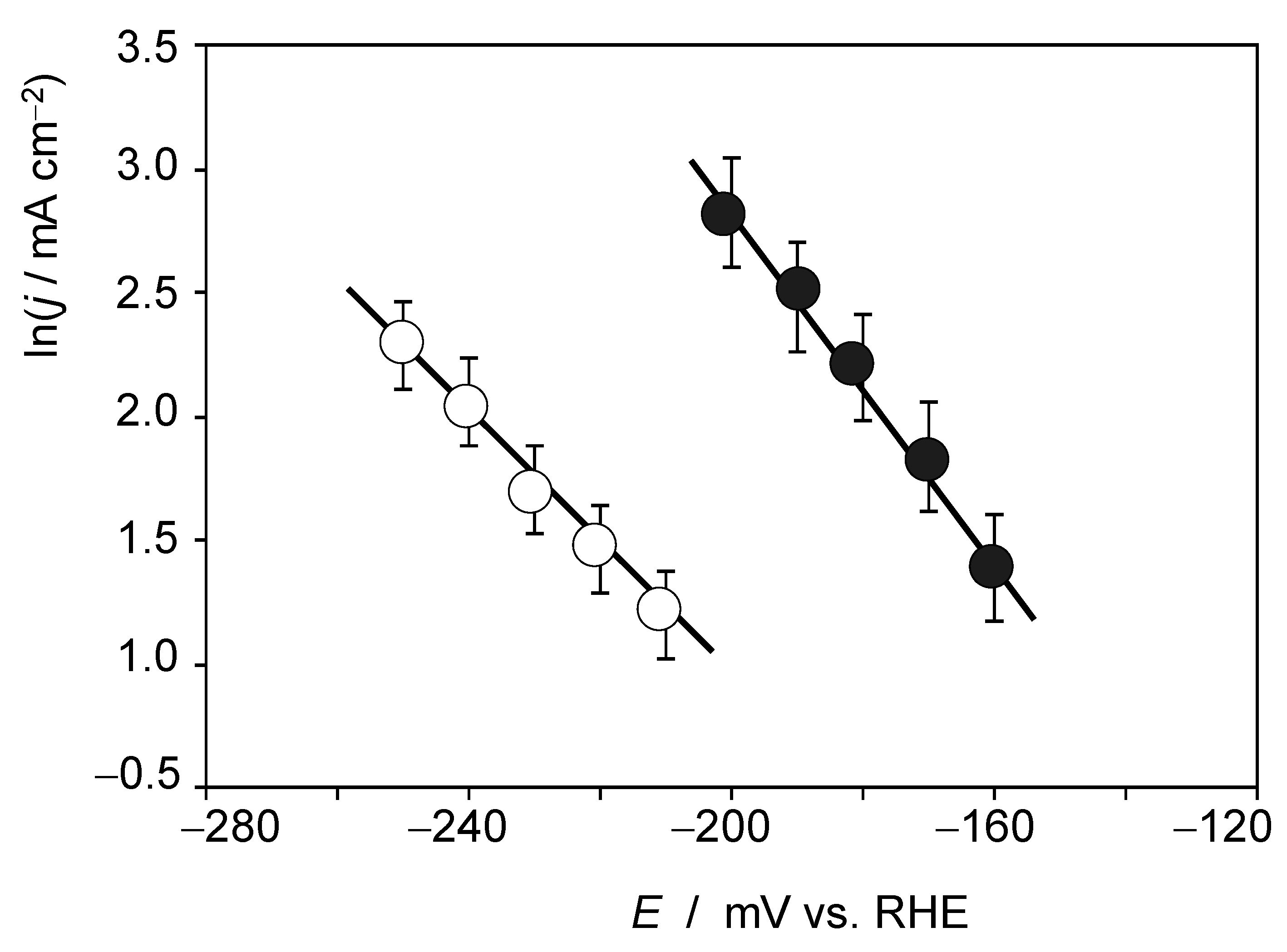
Figure 6.
Variation in the f(ilim) ratio with the square root of the Li+ concentration in CVs at RuP2@N-P-C-modified GCEs recorded under quiescent conditions in contact with 0.50 M H2SO4 + LiClO4 solutions in conditions such as those in Figure S12. The continuous line corresponds to the polynomial fit of the entire set of data while the dotted line defines the straight line fitting for the values at high concentrations of Li+.

Figure 7.
Impedance spectra of RuP2@N-P-C-modified GCEs in contact with (a,b) 0.50 M H2SO4 and (c,d) 0.50 M H2SO4 + 0.14 M LiClO4 solutions at different bias potentials. (a,c) Nyquist plots of Zreal vs. −Zimag; (b,d) Bode plots of −ϕ vs. logf.
Figure 7.
Impedance spectra of RuP2@N-P-C-modified GCEs in contact with (a,b) 0.50 M H2SO4 and (c,d) 0.50 M H2SO4 + 0.14 M LiClO4 solutions at different bias potentials. (a,c) Nyquist plots of Zreal vs. −Zimag; (b,d) Bode plots of −ϕ vs. logf.


Table 1.
Chemical composition and surface area of N-P-C and RuP2@N-P-C.
| Sample | C (%) | N (%) | P (%) | Ru (%) | H (%) | Surface Area (m2/g) |
|---|---|---|---|---|---|---|
| N-P-C | 59.6 | 1.9 | 3.1 | - | 0.5 | 817 |
| RuP2@N-P-C | 53.1 | 2 | 8.9 | 6.7 | 0.78 | 765 |
Publisher’s Note: MDPI stays neutral with regard to jurisdictional claims in published maps and institutional affiliations. |
© 2022 by the authors. Licensee MDPI, Basel, Switzerland. This article is an open access article distributed under the terms and conditions of the Creative Commons Attribution (CC BY) license (https://creativecommons.org/licenses/by/4.0/).
Share and Cite
MDPI and ACS Style
Anouar, A.; Doménech-Carbó, A.; Garcia, H. Phosphorus-Rich Ruthenium Phosphide Embedded on a 3D Porous Dual-Doped Graphitic Carbon for Hydrogen Evolution Reaction. Nanomaterials 2022, 12, 3597. https://doi.org/10.3390/nano12203597
AMA Style
Anouar A, Doménech-Carbó A, Garcia H. Phosphorus-Rich Ruthenium Phosphide Embedded on a 3D Porous Dual-Doped Graphitic Carbon for Hydrogen Evolution Reaction. Nanomaterials. 2022; 12(20):3597. https://doi.org/10.3390/nano12203597
Chicago/Turabian StyleAnouar, Aicha, Antonio Doménech-Carbó, and Hermenegildo Garcia. 2022. "Phosphorus-Rich Ruthenium Phosphide Embedded on a 3D Porous Dual-Doped Graphitic Carbon for Hydrogen Evolution Reaction" Nanomaterials 12, no. 20: 3597. https://doi.org/10.3390/nano12203597
Note that from the first issue of 2016, this journal uses article numbers instead of page numbers. See further details here.