
Improving Cycle Life of Zinc–Air Batteries with Calcium Ion Additive in Electrolyte or Separator


1
Key Laboratory of Advanced Ceramics and Machining Technology (Ministry of Education), School of Materials Science and Engineering, Tianjin University, No. 135 Yaguan Road, Tianjin 300072, China
2
Tianjin Key Laboratory of Composite and Functional Materials, School of Materials Science and Engineering, Tianjin University, No. 135 Yaguan Road, Tianjin 300072, China
3
Joint School of National University of Singapore and Tianjin University, International Campus of Tianjin University, Fuzhou 350207, China
*
Author to whom correspondence should be addressed.
Nanomaterials 2023, 13(12), 1864; https://doi.org/10.3390/nano13121864
Submission received: 10 May 2023
/
Revised: 7 June 2023
/
Accepted: 11 June 2023
/
Published: 15 June 2023
(This article belongs to the Special Issue Editorial Board Members’ Collection Series: Synthesis and Applications of Nanomaterials for Renewable Energies)
Abstract
:The electrolyte carbonation and the resulting air electrode plugging are the primary factors limiting the cycle life of aqueous alkaline zinc–air batteries (ZABs). In this work, calcium ion (Ca2+) additives were introduced into the electrolyte and the separator to resolve the above issues. Galvanostatic charge–discharge cycle tests were carried out to verify the effect of Ca2+ on electrolyte carbonation. With the modified electrolyte and separator, the cycle life of ZABs was improved by 22.2% and 24.7%, respectively. Ca2+ was introduced into the ZAB system to preferentially react with CO32− rather than K+ and then precipitated granular CaCO3 prior to K2CO3, which was deposited on the surface of the Zn anode and air cathode to form a flower-like CaCO3 layer, thereby prolonging its cycle life.
1. Introduction
Zinc–air batteries (ZABs) have been considered for a stationary energy storage application due to their high theoretical energy densities, abundant resources, low cost, and the environmental compatibility of Zn [1,2,3,4,5,6]. Its semi-open structure, however, inevitably led to the carbonation of electrolyte, and carbon dioxide came from the air as well as the oxidization of C element in air cathode at a high discharge voltage according to Equations (1) and (2) [7,8,9]. It would significantly reduce the cycle life of ZABs and restrict further commercialization [7,8,10,11].
Therefore, mitigating the carbonation of alkaline electrolytes is crucial for the application of alkaline ZABs, and numerous attempts have been carried out to resolve the above issues. An aqueous chloride-based electrolyte has been provided to obtain a long cycle life of over 400 h but with a relatively low overpotential of less than 1.1 V [12]. Various near-neutral electrolytes have also been tested to exhibit better recyclability but suffer from a lower current density and battery capacity due to the inhibition of oxygen evolution reactions (OERs) and the hydrogen evolution reaction (HER) [13,14,15,16,17,18,19,20]. A “water-in-salt” (WIS) gel polymer electrolyte was proposed to achieve a long cycle life, but only with lower operating power [21]. Additionally, both H2SO4 and ZnSO4 were believed to induce the abrupt loss of battery capacity [22,23,24].
The above investigation of existing literature implied that the inefficient inhibition for the carbonation of alkaline electrolytes has severely limited the cycle life of ZABs, and new regulation strategies should be explored. Alkali earth metal cations, such as Ca2+ and Mg2+, exhibited strong adsorption capacity for carbonate ions compared with K+, which means that alkali earth metal cations were more likely to adsorb and bind more carbonate ions than K+ in alkaline electrolytes [25,26,27,28,29,30,31,32,33,34,35,36].
Herein, calcium hydroxide (Ca(OH)2) additive was introduced to modify the electrolyte as well as the membrane by the addition of Ca2+, which were both assembled in the batteries to evaluate its effect. A series of charge–discharge cycle tests were performed, and then each component of the cycled ZAB was also analyzed, including the anode, air cathode, and separator. The morphology and structure were systematically characterized by X-ray diffraction (XRD), Fourier-transform infrared (FTIR), and scanning electron microscopy (SEM). Electrochemical measurements were also conducted to investigate the performance evolution of the air cathode after cycling. In addition, the conductivity of the electrolyte and the concentration of CO32− were also measured to facilitate the analysis of the mechanism of additives.
2. Experimental Section
2.1. Materials
The Zn anode was an 80 × 40 × 1 mm zinc sheet, ground with 800 and 1500 mesh sandpapers in sequence, cleaned and dried with deionized water. Commercial Co3O4/CB air cathode with a 4.5 mg cm−2 mass-loading of submicron-scaled Co3O4 (300 nm) powder was selected, where carbon black (CB, XC-72R) powders and polytetrafluoroethylene (PTFE) were used as the conductive additive and the binders, respectively [37]. A basic electrolyte consisting of 6 M KOH and 0.2 M ZnO with 0.2 M Ca(OH)2 was used as the additive. In addition, Ca(OH)2 was added to the α-Al2O3 ceramic separator to achieve a modified separator, and the detailed composition is listed in Table 1.
Figure 1 shows the schematic of the separator preparation mold, which consists of two parts, as shown in Figure 1a, and Figure 1b exhibits the schematic after assembly. The slurry was dropped onto polypropylene (pp) film on the mold surface and then dried and turned over to repeat the above process until a satisfactory separator was obtained.
2.2. Design and Assembly of ZAB
A typical ZAB mold was applied in this work with the distance between the air cathode and the Zn anode of 1 cm and the active area of the electrode of 4.5 cm2 [38,39,40,41,42,43]. In addition, another set of electrolytic cells was installed to explore the effect of the separator on the cycle life of ZABs, as shown in Figure 2, which consisted of an electrolytic cell and a separator fixing plate (Figure 2a). When installing (Figure 2b), the separator was placed into the electrolytic cell and then pressed tightly with the separator fixing plate. When assembling the battery, both sides of the electrolytic cell were fastened to ensure it was completely sealed without liquid leakage during the test.
2.3. Methods
Galvanostatic charge–discharge cycle tests were measured at a current density of 10 mA cm−2 with a cut-off voltage higher than 5 V or lower than 0 V, using a battery testing system, CT2001A (LanHe Instrument Technology Co., Ltd., Wuhan, China). The cyclic voltammetry (CV), electrochemical impedance spectroscopy (EIS), and linear sweep voltammetry (LSV) were performed at a scan rate of 2 mV s−1 with a voltage range of 0 to ±1 V vs. the saturated calomel electrode (SCE) in the solution of 1 M KOH with O2 saturated, which were carried out by electrochemical workstation (PARSTAT 4000A, Princeton Applied Research, Oak Ridge, TN, USA). All the tests were carried out at room temperature (25 °C) in the atmosphere environment.
X-ray diffraction (XRD, Bruker D8 advanced, Bremen, Germany) was used to analyze the phase composition of the electrodes after cycle testing with a scanning angle from 10° to 90°. Surface morphologies of the electrodes were characterized by field-emission scanning electron microscopy (SEM, JSM-7800F, with EDS, JEOL, Tokyo, Japan). Additionally, the composition was analyzed using a Fourier-transform infrared (FTIR) (FTIR-650, Tianjin Guangdong Co., Ltd., Tianjin, China) with a wavelength range from 4000 to 400 cm−1 and a resolution of 4 cm−1.
The concentration of carbonate ion (CO32−) in the electrolyte was measured by chemical titration. The conductivity of the electrolyte was tested by a REX DDSJ-308F conductivity meter with a platinum electrode of 5 × 5 mm at 28.6 °C (obtained from the conductivity meter) in the atmospheric environment of 101.1 kPa.
3. Results and Discussion
3.1. Charge–Discharge Cycle Performance
To investigate the effect of Ca2+ on the cycle life, ZABs with a modified electrolyte and separator were evaluated with galvanostatic charge–discharge cycle tests; the corresponding results are shown in Figure 3. In addition, a reference ZAB without additives was subjected to the same test as the experimental group. ZABs with a modified electrolyte and separator cycled for 99 h and 101 h, respectively, while the reference one only ran for 81 h, indicating that the addition of the Ca(OH)2 additive into the electrolyte and separator improved the cycle life by 22.2% and 24.7%, respectively [11,37,44,45]. It should be noted that the improvement effect of the modified electrolyte is similar to that of the modified separator, owing to the solubility limitation of Ca(OH)2 in the aqueous electrolyte.
3.2. Morphology and Structure of ZAB Components
To better understand the improvement mechanism of the Ca2+ additive on the cycle life of ZABs, the batteries were disassembled to characterize their components, including the Zn anode, air cathodes, electrolyte, and separator.
Surface morphologies of cycled Zn anodes with a modified electrolyte and separator are shown in Figure 4 and Figure 5, respectively, with the corresponding XRD patterns. The surface of the Zn anodes after cycling was relatively flat with a uniformly distributed convex structure (Figure 4a and Figure 5a). After partial amplification, it can be seen in Figure 4b that the convex structure was a flower-like structure, while the 3D microporous structure was formed by alternating stacking of nanoparticle and lamellar structures, as shown in Figure 5b. The corresponding element distributions of cycled Zn anodes are shown in Figures S1 and S2, where the element of Ca was uniformly distributed while elements of Zn and K elements were locally enriched at the surface bumps. The detailed element content results are listed in Tables S1 and S2, and it could be found that the concentration of Ca element on the surface of the Zn anode was relatively low, consistent with the low content of Ca2+ additive in the modified electrolyte and separator. In Figure 4c and Figure 5c, the peaks are found to correspond quite well with Zn at 36.3° (0 0 2), 39.0° (1 0 0), 43.2° (1 0 1), and 54.3° (1 0 2) (JCPDS No. 87-0713). Moreover, the peaks matched well at 31.8° (1 0 0) and 36.3° (1 0 1) assigning to ZnO (JCPDS No. 36-1451), indicating the generation of ZnO on the anode surface after cycling [46], confirming the corrosion and passivation of Zn anode during galvanostatic charge–discharge process [47]. Important to note that characteristic peaks of CaCO3 (JCPDS No. 76-0606) are detected at 23.0° (0 2 0), 26.2° (1 1 1), 27.2° (0 2 1), 31.1° (0 0 2), 32.7° (1 2 1), 76.6° (2 0 4), 82.3° (1 6 2) and 86.4° (2 3 4), indicating the formation of CaCO3 after cycling [26,27,28]. It could be concluded that CO32– was adsorbed and combined with Ca2+ to form CaCO3 during cycling when adding Ca(OH)2 into the electrolyte and separator [26,27,28,29,30], which generated flower-like CaCO3 layer to provide the transport channel of OH−, thereby improving the cycle life of ZABs [48].
Surface morphologies of the air cathode after cycling with a modified electrolyte and separator are shown in Figure 6 and Figure 7, respectively, with the corresponding XRD patterns. The lamellar convex structure was evenly distributed on the surface of the air cathode, as shown in Figure 6a and Figure 7a, and the lamellar convex structure and fine particles were alternately distributed, as shown in Figure 6b and Figure 7b. According to the element distribution characterization (Figures S3 and S4) and the detailed element content (Tables S3 and S4), the element of K was densely distributed on the surface of the air cathode with relatively higher coverage, while the element of Ca was enriched around spherical particles in a small amount. In addition, elements of C and O were accumulated at the enrichment sites of K and Ca, and the element of Co was only observed in local areas. In Figure 6c and Figure 7c, the peaks are consistent with Co3O4 (JCPDS No. 74-2120) at 19.0° (1 1 1), 31.3° (2 2 0), 36.8° (3 1 1), 44.8° (4 0 0), 59.3° (5 1 1), and 65.2° (4 4 0). Additionally, the peaks detected at 25.1° (0 0 2), 31.0° (1 0 2), 31.6° (1 1 0), and 38.8° (2 0 1) are assigned to the K2CO3 (JCPDS No. 27-1348), and the peaks of CaCO3 can be clearly observed at 23.0° (0 2 0), 26.2° (1 1 1), 27.2° (0 2 1), 31.1° (0 0 2), 32.7° (1 2 1), 72.4° (1 2 4), and 77.1° (0 5 3) (JCPDS No. 76-0606). It could be demonstrated that K2CO3 and CaCO3 were generated during charge–discharge cycling [7,8,11,26,27,28,37]. Considering the voltage loss (i.e., iR drop) caused by the electrolyte solution between the working electrode and the reference electrode, corrected ORR and OER performance of the cycled air cathode by iR compensation was investigated in Figure 8, and both of them were significantly decreased after cycling, and its performance with a modified electrolyte deteriorated more than the one with a modified separator [8,11,26,27,28,29,30,49,50]. After cycling, the micropores of the air cathode could easily be blocked by the generated lamellar K2CO3, hindering the diffusion of O2 through the air cathode to participate in ORR and OER reaction, resulting in the remarkable decrease in ORR and OER performance of air cathode. In comparison, the flower-like porous structure formed by granular CaCO3 on the surface of the air cathode could provide gas diffusion channels, and thus both ORR and OER activity of the air cathode could be improved to a certain extent, exhibiting a relatively low decrease in the performance.
The conductivity and concentration of CO32− in the electrolyte were measured to clarify the effect of Ca2+, and the detailed values are summarized in Table 2 and Table 3. Prior cycling, the conductivity increased by 2.5% from 63.26 × 10⁻² S cm−1 to 64.85 × 10⁻² S cm−1 when adding 0.2 mol L−1 Ca(OH)2. After cycling, the conductivity of the modified electrolyte decreased by 36.1% to 41.46 × 10⁻² S cm−1, while the responding value with the modified separator decreased by 39.3% to 38.43 × 10⁻² S cm−1, which was attributed to the increased resistance caused by the consumption of conductive ions as well as the production of CaCO3 [26,27,28]. Remarkable changes were detected in the concentration of CO32− when adding Ca(OH)2, which significantly decreased from 6.182 mol L−1 to 0.800 mol L−1 or 0.547 mol L−1 after cycling with the modified electrolyte or separator, respectively, as shown in Table 3 [8,11,44]. Ca2+ was introduced into the ZAB system to preferentially react with CO32− rather than K+, resulting in the precipitation of granular CaCO3 prior to K2CO3 [51], alleviating the blocking effect of micropores on the air electrode surface induced by the carbonation of alkaline electrolyte. Moreover, the modified separator would continuously release Ca2+ to the electrolyte to consume CO32− during the charge–discharge process, maintaining a relatively low concentration of CO32− in the electrolyte to achieve sustained long-term improvement [48].
Surface morphologies of the modified separator on both sides were investigated before and after cycling, as shown in Figure 9, and the corresponding XRD patterns are exhibited in Figure 10. Prior to cycling, the fresh separator (Figure 9a) is relatively flat, with micropores, whiskers, and nano-spherical structures scattered and uniformly distributed on its surface. After cycling, small spherical structures were observed on the separator when contacting the Zn anode (Figure 9b), forming a loose 3D structure with micropores and whiskers alternately appearing and uniformly distributed on the surface, while at the side contacting the air cathode (Figure 9c), a relatively smoother surface could be found with layered and nano-spherical structures. Combining with the element distribution characterization (Figures S5–S7) and the detailed element content (Tables S5–S7), elements of C, O, Al, K, Ca, and Zn were uniformly distributed on both sides of the separator. Additionally, elements of Ti and Zr were enriched in the surface bumps, and the distribution of Ca, C, and O elements overlapped, indicating the formation of CaCO3. According to XRD results in Figure 10, the peaks detected at 31.8° (1 0 0) and 36.3° (1 0 1) at the side of the separator contacting the Zn anode referred to ZnO (JCPDS No.36-1451), and the peaks at 26.2° (1 1 1), 27.2° (0 2 1), 33.1° (0 1 2), 37.8° (1 1 2), 42.9° (1 2 2), and 45.9° (2 2 1) are related with CaCO3 (JCPDS No. 76-0606), indicating the generation of ZnO and CaCO3 during cycling [26,27,28]. By comparing the infrared spectrum of Ca(OH)2 and CaCO3 in Figure S8, it could be found that the peak of OH− at 3642 cm−1 became weaker with enhanced peaks of C–O at 1432 cm−1 and 876 cm−1 after cycling, implying the formation of CaCO3 to consume CO2 by the absorption of Ca2+ [29,31,33,34,36,48].
3.3. Mechanism of Ca2+ Additive to Improve the Cycle Life of ZABs
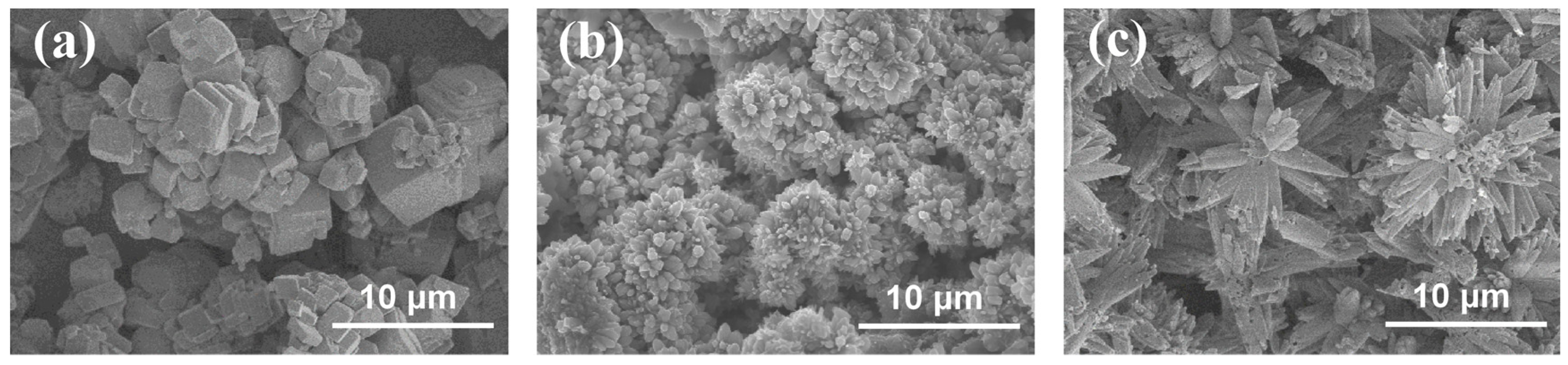
To clarify the mechanism of the Ca2+ additive in improving the cycle life of ZABs, the morphologies of the CaCO3 crystal on the surface of the Zn anode and the air cathode were further characterized by the flower-like structures [48] shown in Figure 11b,c, respectively, exhibiting significant differences from that of the CaCO3 calcite particles (Figure 11a). It could be concluded that such flower-like-shaped CaCO3 films with large gaps between the crystals provided ion transport channels for electrochemical reactions during the charge and discharge processes, which prevented the blockage of the air cathode by lamellar K2CO3 crystals [26,27,28,29,30]. This phenomenon occurred mainly due to the strong electrostatic attraction coordinating unsaturated Ca2+ in the surface of CaCO3 to CO32− [25]. Besides that, CaCO3 exhibited relatively lower solubility compared with that of K2CO3, resulting in the preferential combination of Ca2+ with CO32− in the electrolyte to produce CaCO3 prior to K2CO3 [52]. It could alleviate the carbonation of the electrolyte as well as the blockage of the air cathode [26,27,28,29,30], effectively improving the cycle life of ZABs [48].
4. Conclusions
In order to alleviate the carbonation of electrolytes to improve the cycle life of ZABs, Ca2+ was introduced to modify the electrolyte and the separator. Galvanostatic charge–discharge cycling tests were conducted with morphology and structure analysis of various battery components; subsequently, it could be found that the cycle life of ZABs was improved obviously by 22.2% and 24.7% with the Ca(OH)2-modified electrolyte and separator, respectively. When adding Ca(OH)2 into the electrolyte and the separator, CO32− was adsorbed to combine with Ca2+ to form CaCO3 during cycling. The generated CaCO3 deposited on the Zn anode and air cathode to produce a flower-like CaCO3 layer, which provided ion transport channels for electrochemical reactions during charge–discharge cycles and alleviated the blockage of the air cathode by lamellar K2CO3 crystals, thereby improving the cycle life of ZABs.
Supplementary Materials
The following supporting information can be downloaded at: https://www.mdpi.com/article/10.3390/nano13121864/s1. Figure S1: Element distribution of Zn anode after cycle testing of ZAB with modified electrolyte: (a) Ca, (b) Zn, (c) C, (d) O and (e) K. Figure S2: Element distribution of Zn anode after cycle testing of ZAB with modified separator: (a) Ca, (b) Zn, (c) C, (d) O and (e) K. Figure S3: Element distribution of air cathode after cycle testing of ZAB with modified electrolyte: (a) Ca, (b) Co, (c) C, (d) O and (e) K. Figure S4: Element distribution of air cathode after cycle testing of ZAB with modified separator: (a) Ca, (b) Co, (c) C, (d) O and (e) K. Figure S5: Element distribution of the modified separator before cycle testing of ZAB: (a) C, (b) O, (c) Al, (d) K, (e) Ca, (f) Ti and (g) Zr. Figure S6: Element distribution of the modified separator at the side contacting with Zn anode after cycle testing of ZAB: (a) C, (b) O, (c) Al, (d) K, (e) Ca, (f) Ti, (g) Zn and (h) Zr. Figure S7: Element distribution of the modified separator at the side contacting with air cathode after cycle testing of ZAB: (a) C, (b) O, (c) Al, (d) K, (e) Ca, (f) Ti, (g) Co and (h) Zr. Figure S8: FT-IR patterns of the modified separator (a) before and (b) after cycle testing of ZAB. Tabel S1: Element content of Zn anode after cycle testing of ZAB with modified electrolyte. Tabel S2: Element content of Zn anode after cycle testing of ZAB with modified separator. Tabel S3: Element content of air cathode after cycle testing of ZAB with modified electrolyte. Tabel S4: Element content of air cathode after cycle testing of ZAB with modified separator. Tabel S5: Element content of the modified separator before cycle testing of ZAB. Tabel S6: Element content of the modified separator at the side contacting with Zn anode after cycle testing of ZAB. Tabel S7: Element content of the modified separator at the side contacting with air cathode after cycle testing of ZAB.
Author Contributions
Conceptualization, W.H. and D.Z.; methodology, D.Z.; software, D.Z.; validation, W.H. and D.Z.; formal analysis, D.Z.; investigation, D.Z.; resources, W.H.; data curation, D.Z.; writing—original draft preparation, D.Z.; writing—review and editing, W.H.; visualization, W.H.; project administration, D.Z. and W.H.; funding acquisition, W.H. All authors have read and agreed to the published version of the manuscript.
Funding
This work was supported by the National Natural Science Foundation of Guangdong Province (No. U1601216).
Data Availability Statement
Not applicable.
Acknowledgments
We appreciate the excellent technical assistance provided by Cheng (Tianjin University).
Conflicts of Interest
The authors declare no conflict of interest.
References
- Lutkenhaus, J.L.; Flouda, P. Structural batteries take a load off. Sci. Robot. 2020, 5, eabd7026. [Google Scholar] [CrossRef] [PubMed]
- Li, Y.; Dai, H. Recent advances in zinc–air batteries. Chem. Soc. Rev. 2014, 43, 5257–5275. [Google Scholar] [CrossRef] [PubMed] [Green Version]
- Liu, X.; Yuan, Y.; Liu, J.; Liu, B.; Chen, X.; Ding, J.; Han, X.; Deng, Y.; Zhong, C.; Hu, W. Utilizing solar energy to improve the oxygen evolution reaction kinetics in zinc–air battery. Nat. Commun. 2019, 10, 4767. [Google Scholar] [CrossRef] [PubMed] [Green Version]
- Yang, Z.; Zhang, J.; Kintner-Meyer, M.C.W.; Lu, X.; Choi, D.; Lemmon, J.P.; Liu, J. Electrochemical energy storage for green grid. Chem. Rev. 2011, 111, 3577–3613. [Google Scholar] [CrossRef] [PubMed]
- Li, Y.; Gong, M.; Liang, Y.; Feng, J.; Kim, J.E.; Wang, H.; Hong, G.; Zhang, B.; Dai, H. Advanced zinc-air batteries based on high-performance hybrid electrocatalysts. Nat. Commun. 2013, 4, 1805. [Google Scholar] [CrossRef] [Green Version]
- Nie, Y.; Xu, X.; Wang, X.; Liu, M.; Gao, T.; Liu, B.; Li, L.; Meng, X.; Gu, P.; Zou, J. CoNi alloys encapsulated in N-doped carbon nanotubes for stabilizing oxygen electrocatalysis in zinc-air battery. Nanomaterials 2023, 13, 1788. [Google Scholar] [CrossRef]
- Chang, J.; Wang, G.; Yang, Y. Recent advances in electrode design for rechargeable zinc–air batteries. Small Sci. 2021, 1, 2100044. [Google Scholar] [CrossRef]
- He, Y.; Shang, W.; Ni, M.; Huang, Y.; Zhao, H.; Tan, P. In-situ observation of the gas evolution process on the air electrode of Zn-air batteries during charging. Chem. Eng. J. 2022, 427, 130862. [Google Scholar] [CrossRef]
- Wang, M.; Huang, X.; Yu, Z.; Zhang, P.; Zhai, C.; Song, H.; Xu, J.; Chen, K. A stable rechargeable aqueous Zn-air battery enabled by heterogeneous MoS2 cathode catalysts. Nanomaterials 2022, 12, 4069. [Google Scholar] [CrossRef]
- Shang, W.; Yu, W.; Liu, Y.; Li, R.; Dai, Y.; Cheng, C.; Tan, P.; Ni, M. Rechargeable alkaline zinc batteries: Progress and challenges. Energy Storage Mater. 2020, 31, 44–57. [Google Scholar] [CrossRef]
- Zhong, Y.; Liu, B.; Zhao, Z.; Shen, Y.; Liu, X.; Zhong, C. Influencing factors of performance degradation of zinc–air batteries exposed to air. Energies 2021, 14, 2607. [Google Scholar] [CrossRef]
- Iruin, E.; Mainar, A.R.; Enterría, M.; Ortiz-Vitoriano, N.; Blázquez, J.A.; Colmenares, L.C.; Rojo, T.; Clark, S.; Horstmann, B. Designing a manganese oxide bifunctional air electrode for aqueous chloride-based electrolytes in secondary zinc-air batteries. Electrochim. Acta 2019, 320, 134557. [Google Scholar] [CrossRef]
- Li, M.; Liu, B.; Fan, X.; Liu, X.; Liu, J.; Ding, J.; Han, X.; Deng, Y.; Hu, W.; Zhong, C. Long-shelf-life polymer electrolyte based on tetraethylammonium hydroxide for flexible zinc–air batteries. ACS Appl. Mater. Interfaces 2019, 11, 28909–28917. [Google Scholar] [CrossRef] [PubMed]
- Li, Y.; Fan, X.Y.; Liu, X.; Qu, S.; Zhong, C. Long-battery-life flexible zinc–air battery with near-neutral polymer electrolyte and nanoporous integrated air electrode. J. Mater. Chem. A 2019, 7, 25449–25457. [Google Scholar] [CrossRef]
- Song, Z.; Ding, J.; Liu, B.; Liu, X.; Han, X.; Deng, Y.; Hu, W.; Zhong, C. A rechargeable Zn–air battery with high energy efficiency and long life enabled by a highly water-retentive gel electrolyte with reaction modifier. Adv. Mater. 2020, 32, 1908127. [Google Scholar] [CrossRef]
- Song, Z.; Ding, J.; Liu, B.; Liu, X.; Han, X.; Deng, Y.; Hu, W.; Zhong, C. Zinc–air batteries: A rechargeable Zn-air battery with high energy efficiency and long life enabled by a highly water-retentive gel electrolyte with reaction modifier (Adv. Mater. 22/2020). Adv. Mater. 2020, 32, 2070172. [Google Scholar] [CrossRef]
- Tran, T.N.T.; Clark, M.P.; Xiong, M.; Chung, H.J.; Ivey, D.G. A tri-electrode configuration for zinc-air batteries using gel polymer electrolytes. Electrochim. Acta 2020, 357, 136865. [Google Scholar] [CrossRef]
- Yi, J.; Liang, P.; Liu, X.; Wu, K.; Liu, Y.; Wang, Y.; Xia, Y.; Zhang, J. Challenges, mitigation strategies and perspectives in development of zinc-electrode materials and fabrication for rechargeable zinc–air batteries. Energy Environ. Sci. 2018, 11, 3075–3095. [Google Scholar] [CrossRef] [Green Version]
- Yan, X.; Tong, Y.; Liu, Y.; Li, X.; Qin, Z.; Wu, Z.; Hu, W. Highly reversible Zn anodes through a hydrophobic interface formed by electrolyte additive. Nanomaterials 2023, 13, 1547. [Google Scholar] [CrossRef]
- Lorca, S.; Torres, J.; Serrano, J.L.; Pérez, J.; Abad, J.; Santos, F.; Fernández Romero, A.J. Bifunctional P-containing RuO2 catalysts prepared from surplus Ru Co-ordinationcomplexes and applied to Zn/air batteries. Nanomaterials 2023, 13, 115. [Google Scholar] [CrossRef]
- Zhang, Y.; Wu, D.; Huang, F.; Cai, Y.; Li, Y.; Ke, H.; Lv, P.; Wei, Q. “Water-in-Salt” nonalkaline gel polymer electrolytes enable flexible zinc-air batteries with ultra-long operating time. Adv. Funct. Mater. 2022, 32, 2203204. [Google Scholar] [CrossRef]
- Kim, S.H.; Oh, S.M. Degradation mechanism of layered MnO2 cathodes in Zn/ZnSO4/MnO2 rechargeable cells. J. Power Sources 1998, 72, 150–158. [Google Scholar] [CrossRef]
- Yamamoto, T.; Shoji, T. Rechargeable Zn|ZnSO4|MnO2-type cells. Inorg. Chim. Acta 1986, 117, L27–L28. [Google Scholar] [CrossRef]
- Tan, X.; Guo, G.; Wang, K.; Zhang, H. Synthesis and electrochemical performance of the orthorhombic V2O5·nH2O nanorods as cathodes for aqueous zinc batteries. Nanomaterials 2022, 12, 2530. [Google Scholar] [CrossRef]
- Herries, J.J. An In-Situ Fourier Transform Infrared Spectroscopy Investigation of the Adsorption of Organic and Inorganic Adsorbates at the Mineral Oxide Surface; University of Wyoming: Laramie, WY, USA, 2003. [Google Scholar]
- Baltrusaitis, J.; Schuttlefield, J.D.; Zeitler, E.; Jensen, J.H.; Grassian, V.H. Surface reactions of carbon dioxide at the adsorbed water-oxide interface. J. Phys. Chem. C 2007, 111, 14870–14880. [Google Scholar] [CrossRef]
- Palmer, S.J.; Frost, R.L.; Nguyen, T. Hydrotalcites and their role in coordination of anions in Bayer liquors: Anion binding in layered double hydroxides. Coord. Chem. Rev. 2009, 253, 250–267. [Google Scholar] [CrossRef] [Green Version]
- Lis, D.; Backus, E.H.; Hunger, J.; Parekh, S.H.; Bonn, M. Liquid flow along a solid surface reversibly alters interfacial chemistry. Science 2014, 344, 1138–1142. [Google Scholar] [CrossRef]
- Lefèvre, G. In situ Fourier-transform infrared spectroscopy studies of inorganic ions adsorption on metal oxides and hydroxides. Adv. Colloid Interface Sci. 2004, 107, 109–123. [Google Scholar] [CrossRef] [Green Version]
- Baltrusaitis, J.; Schuttlefield, J.; Zeitler, E.; Grassian, V.H. Carbon dioxide adsorption on oxide nanoparticle surfaces. Chem. Eng. J. 2011, 170, 471–481. [Google Scholar] [CrossRef]
- Du, H.; Williams, C.T.; Ebner, A.D.; Ritter, J.A. In situ FTIR spectroscopic analysis of carbonate transformations during adsorption and desorption of CO2 in K-Promoted HTlc. Chem. Mater. 2010, 22, 3519–3526. [Google Scholar] [CrossRef]
- Baltrusaitis, J.; Grassian, V.H. Surface reactions of carbon dioxide at the adsorbed water-iron oxide interface. J. Phys. Chem. B 2005, 109, 12227–12230. [Google Scholar] [CrossRef] [PubMed]
- Su, C.; Suarez, D.L. In situ infrared speciation of adsorbed carbonate on aluminum and iron oxides. Clays Clay Miner. 1997, 45, 814–825. [Google Scholar] [CrossRef]
- Nakamoto, K.; Fujita, J.; Tanaka, S.; Kobayashi, M. Infrared spectra of metallic complexes. IV. Comparison of the infrared spectra of unidentate and bidentate metallic complexes. J. Am. Chem. Soc. 1957, 79, 4904–4908. [Google Scholar] [CrossRef]
- Rimsza, J.M.; Sorte, E.G.; Alam, T.M. Hydration and hydroxylation of MgO in solution: NMR identification of proton-containing intermediate phases. ACS Omega 2019, 4, 1033–1044. [Google Scholar] [CrossRef]
- Miller, J.D.; Hiskey, J.B. Electrokinetic behavior of fluorite as influenced by surface carbonation. J. Colloid Interface Sci. 1972, 41, 567–573. [Google Scholar] [CrossRef]
- Li, Z.; Han, W.; Jia, P.; Li, X.; Jiang, Y.; Ding, Q. Co3O4 nanoneedle array grown on carbon fiber paper for air cathodes towards flexible and rechargeable Zn-air batteries. Nanomaterials 2021, 11, 3321. [Google Scholar] [CrossRef] [PubMed]
- Zhang, D.; Hu, W. Study on failure mechanism on rechargeable alkaline zinc–air battery during charge/discharge cycles at different depths of discharge. Front. Chem. 2023, 11, 1121215. [Google Scholar] [CrossRef] [PubMed]
- Wang, K.; Pei, P.; Wang, Y.; Liao, C.; Wang, W.; Huang, S. Advanced rechargeable zinc-air battery with parameter optimization. Appl. Energy 2018, 225, 848–856. [Google Scholar] [CrossRef]
- Ma, H.; Wang, B.; Fan, Y.; Hong, W. Development and characterization of an electrically rechargeable zinc-air battery stack. Energies 2014, 7, 6549–6557. [Google Scholar] [CrossRef] [Green Version]
- Muller, S.; Haas, O. Development of a 100 W rechargeable bipolar zinc/oxygen battery. J. Appl. Electrochem. 1998, 28, 305–310. [Google Scholar] [CrossRef]
- An, T.; Ge, X.; Tham, N.N.; Sumboja, A.; Liu, Z.; Zong, Y. Facile one-pot synthesis of CoFe alloy nanoparticles decorated N-Doped carbon for high-performance rechargeable zinc–air battery stacks. ACS Sustain. Chem. Eng. 2018, 6, 7743–7751. [Google Scholar] [CrossRef]
- Hong, W. A Horizontal three-electrode structure for zinc-air batteries with long-term cycle life and high performance. Int. J. Electrochem. Sci. 2016, 11, 3843–3851. [Google Scholar] [CrossRef]
- Song, Z.; Ding, J.; Liu, B.; Shen, Y.; Liu, J.; Han, X.; Deng, Y.; Zhong, C.; Hu, W. Investigation of failure mechanism of rechargeable zinc–air batteries with Poly(acrylic acid) alkaline gel electrolyte during discharge–charge cycles at different current densities. Chem. Eng. J. 2022, 429, 132331. [Google Scholar] [CrossRef]
- Wang, L.; Xu, Z.; Peng, T.; Liu, M.; Zhang, L.; Zhang, J. Bifunctional single-atom cobalt electrocatalysts with dense active sites prepared via a silica xerogel strategy for rechargeable zinc–air batteries. Nanomaterials 2022, 12, 381. [Google Scholar] [CrossRef]
- Beverskog, B.; Puigdomenech, I. Revised pourbaix diagrams for zinc at 25–300 °C. Corros. Sci. 1997, 39, 107–114. [Google Scholar] [CrossRef]
- Thangavel, S.; Chen, P.T.; Yan, W.M.; Yang, C.J.; Huang, K.D. Protection efficiencies of surface-active inhibitors in zinc-air batteries. Int. J. Energy Res. 2020, 44, 11883–11893. [Google Scholar] [CrossRef]
- Kang, L.; Cui, M.; Jiang, F.; Gao, Y.; Luo, H.; Liu, J.; Liang, W.; Zhi, C. Nanoporous CaCO3 coatings enabled uniform Zn stripping/plating for long-life zinc rechargeable aqueous batteries. Adv. Energy Mater. 2018, 8, 1801090. [Google Scholar] [CrossRef]
- Zheng, W. iR compensation for electrocatalysis studies: Considerations and recommendations. ACS Energy Lett. 2023, 8, 1952–1958. [Google Scholar] [CrossRef]
- Tan, H.; Liu, X.; Wang, M.; Huang, H.; Huang, P. Co3O4 supported on graphene-like carbon by one-step calcination of cobalt phthalocyanine for efficient oxygen reduction reaction under alkaline medium. Nanomaterials 2023, 13, 1241. [Google Scholar] [CrossRef]
- Yang, S.; Kim, K. Observation of water consumption in Zn–air secondary batteries. J. Electrochem. Sci. Technol. 2019, 10, 381–386. [Google Scholar] [CrossRef]
- Hodgman, C. Handbook of Chemistry and Physics; CRC Press: Boca Raton, FL, USA, 1924. [Google Scholar]
Figure 1.
Schematic of the separator preparation mold. (a) Schematic diagram of each component, (b) Schematic diagram of the assembled mold.
Figure 1.
Schematic of the separator preparation mold. (a) Schematic diagram of each component, (b) Schematic diagram of the assembled mold.

Figure 2.
Schematic of electrolytic cell mold that can be installed with a separator. (a) Schematic diagram of each component, (b) Schematic diagram of the assembled mold.
Figure 2.
Schematic of electrolytic cell mold that can be installed with a separator. (a) Schematic diagram of each component, (b) Schematic diagram of the assembled mold.
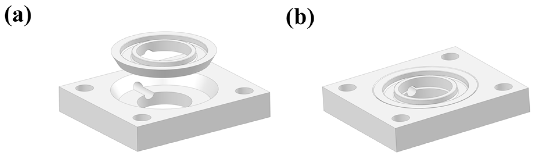
Figure 3.
Galvanostatic charge–discharge cycles of zinc–air batteries.
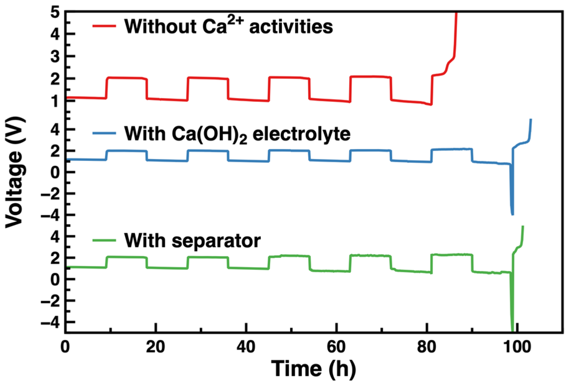
Figure 4.
Surface morphology (a,b) and XRD patterns (c) of Zn anode after galvanostatic charge–discharge cycles of ZAB with modified electrolyte.
Figure 4.
Surface morphology (a,b) and XRD patterns (c) of Zn anode after galvanostatic charge–discharge cycles of ZAB with modified electrolyte.
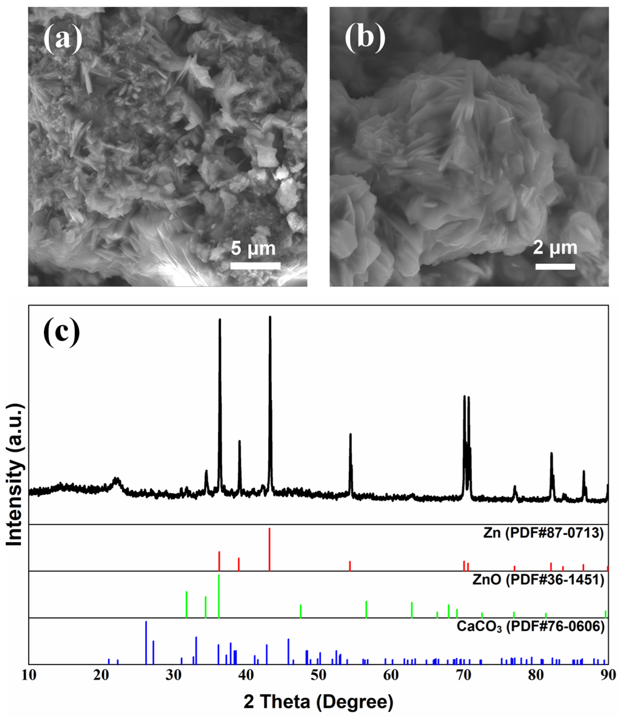
Figure 5.
Surface morphology (a,b) and XRD patterns (c) of Zn anode after galvanostatic charge–discharge cycles of ZAB with modified separator.
Figure 5.
Surface morphology (a,b) and XRD patterns (c) of Zn anode after galvanostatic charge–discharge cycles of ZAB with modified separator.

Figure 6.
Surface morphology (a,b) and XRD patterns (c) of air cathode after galvanostatic charge–discharge cycles of ZAB with modified electrolyte.
Figure 6.
Surface morphology (a,b) and XRD patterns (c) of air cathode after galvanostatic charge–discharge cycles of ZAB with modified electrolyte.

Figure 7.
Surface morphology (a,b) and XRD patterns (c) of air cathode after galvanostatic charge–discharge cycles of ZAB with modified separator.
Figure 7.
Surface morphology (a,b) and XRD patterns (c) of air cathode after galvanostatic charge–discharge cycles of ZAB with modified separator.
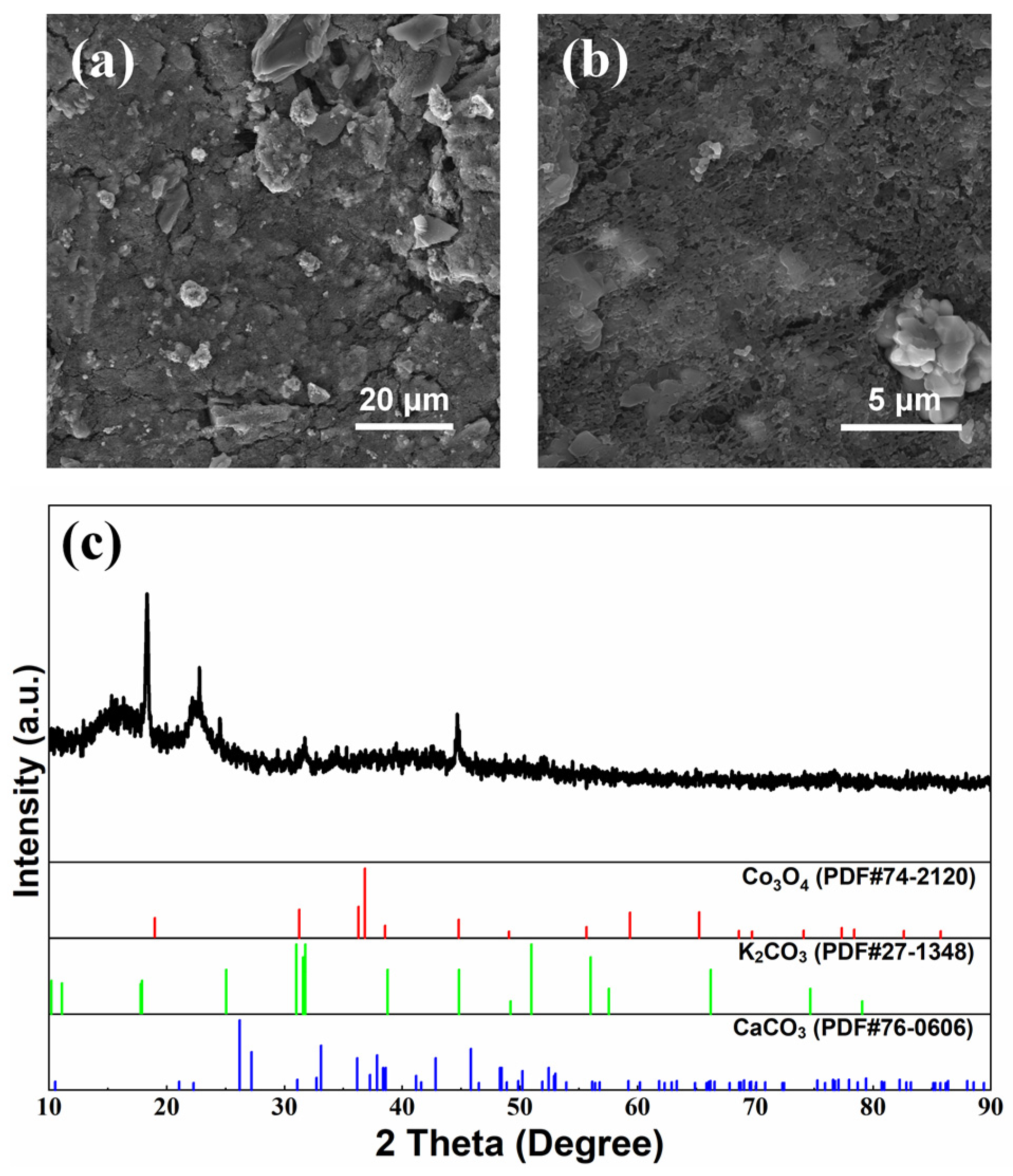
Figure 8.
(a) ORR and (b) OER curves of air cathode after charge-discharge cycles of ZAB.
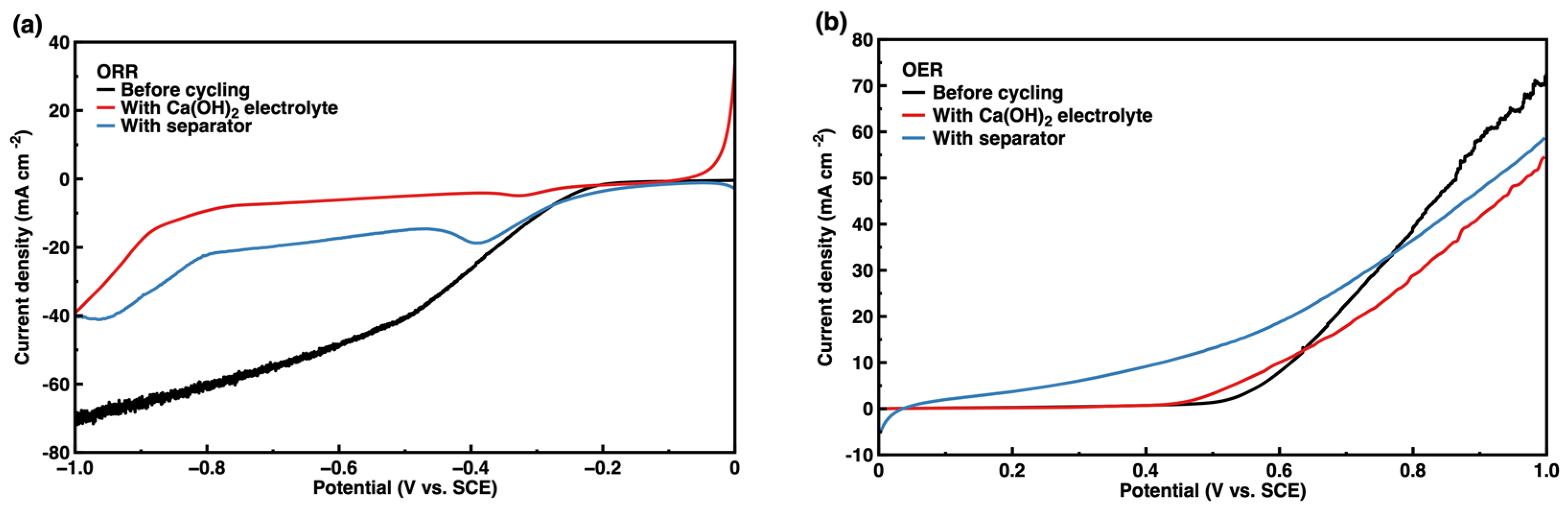
Figure 9.
Surface morphology of the separator (a) before cycling and after cycling on different sides contacting the (b) Zn anode and (c) air cathode.
Figure 9.
Surface morphology of the separator (a) before cycling and after cycling on different sides contacting the (b) Zn anode and (c) air cathode.
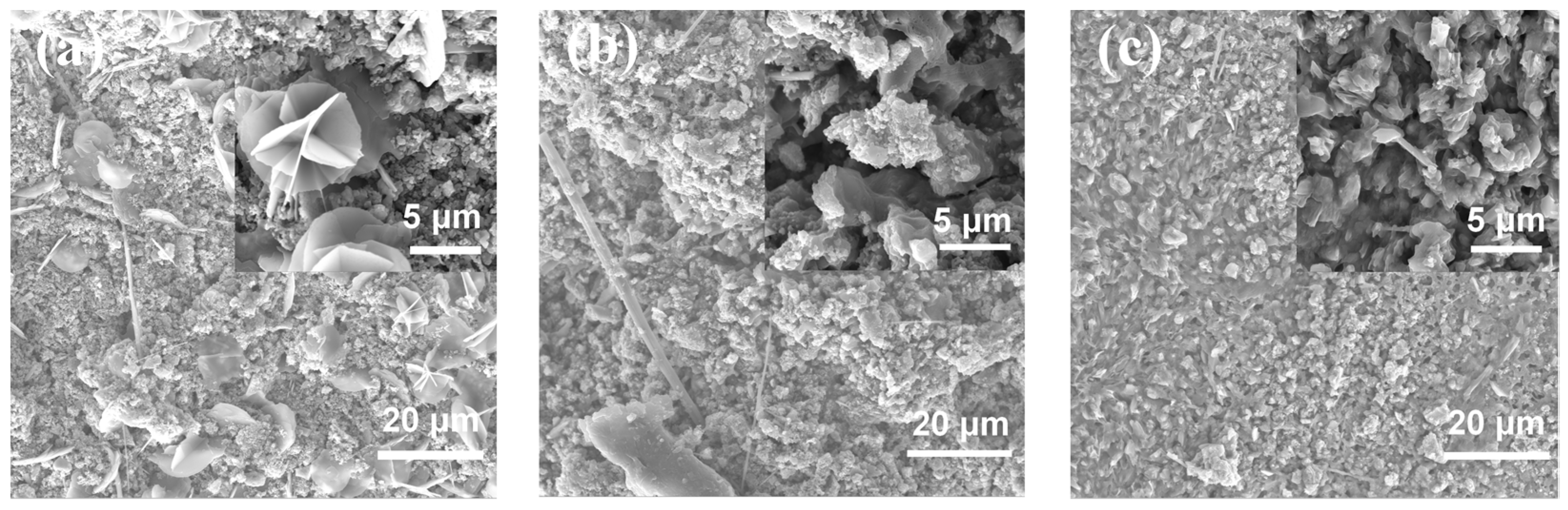
Figure 10.
XRD patterns of the fresh separator (black line) before galvanostatic charge–discharge cycles of ZAB, and side to Zn anode (red line) and side to air cathode (blue line) after testing.
Figure 10.
XRD patterns of the fresh separator (black line) before galvanostatic charge–discharge cycles of ZAB, and side to Zn anode (red line) and side to air cathode (blue line) after testing.

Figure 11.
Morphologies of (a) CaCO3 calcspar and the CaCO3 on the surface of (b) Zn anode and (c) air cathode after galvanostatic charge–discharge cycles of ZAB with modified electrolyte.
Figure 11.
Morphologies of (a) CaCO3 calcspar and the CaCO3 on the surface of (b) Zn anode and (c) air cathode after galvanostatic charge–discharge cycles of ZAB with modified electrolyte.

Table 1.
Composition of the modified separator.
| Composition | Weight/g | Purity | Brand |
|---|---|---|---|
| α-Al2O3 | 30.0 | 99.99% | Xinjiang Joinworld |
| Ca(OH)2 | 10.0 | 95% | Meryer |
| ZrO2 | 10.0 | 99% | Sigma-Aldrich |
| K2O·nTiO2 | 5.0 | 98% | 9dingchem |
| PVA-124 | 1.0 | AR | Meryer |
| CMC | 1.0 | 98% | Chemreagent |
| C12H25SO4Na | 0.5 | 99% | Sigma-Aldrich |
Table 2.
Conductivity of the ZAB electrolyte.
| State | Conductivity/×10−2 S cm−1 | |
|---|---|---|
| Before cycling | Basic electrolyte | 63.26 |
| Modified electrolyte | 64.85 | |
| After cycling | 41.46 | |
| Modified separator | 38.43 |
Table 3.
Concentration of CO32− in ZAB electrolyte after cycling.
| Without Ca2+ Additive | Modified Electrolyte | Modified Separator | |
|---|---|---|---|
| Concentration of CO32−/mol L−1 | 6.182 | 0.800 | 0.547 |
Disclaimer/Publisher’s Note: The statements, opinions and data contained in all publications are solely those of the individual author(s) and contributor(s) and not of MDPI and/or the editor(s). MDPI and/or the editor(s) disclaim responsibility for any injury to people or property resulting from any ideas, methods, instructions or products referred to in the content. |
© 2023 by the authors. Licensee MDPI, Basel, Switzerland. This article is an open access article distributed under the terms and conditions of the Creative Commons Attribution (CC BY) license (https://creativecommons.org/licenses/by/4.0/).
Share and Cite
MDPI and ACS Style
Zhang, D.; Hu, W. Improving Cycle Life of Zinc–Air Batteries with Calcium Ion Additive in Electrolyte or Separator. Nanomaterials 2023, 13, 1864. https://doi.org/10.3390/nano13121864
AMA Style
Zhang D, Hu W. Improving Cycle Life of Zinc–Air Batteries with Calcium Ion Additive in Electrolyte or Separator. Nanomaterials. 2023; 13(12):1864. https://doi.org/10.3390/nano13121864
Chicago/Turabian StyleZhang, Donghao, and Wenbin Hu. 2023. "Improving Cycle Life of Zinc–Air Batteries with Calcium Ion Additive in Electrolyte or Separator" Nanomaterials 13, no. 12: 1864. https://doi.org/10.3390/nano13121864
Note that from the first issue of 2016, this journal uses article numbers instead of page numbers. See further details here.