
Heat Treatment and Dynamic Mechanical Analysis Strain Sweep Effects on the Phase Structure and Morphology of an Fe-28Mn-6Si-5Cr Shape Memory Alloy
 , ,
, ,  ,
,  ,
,  and
and
Abstract
:1. Introduction
2. Materials and Methods
3. Results
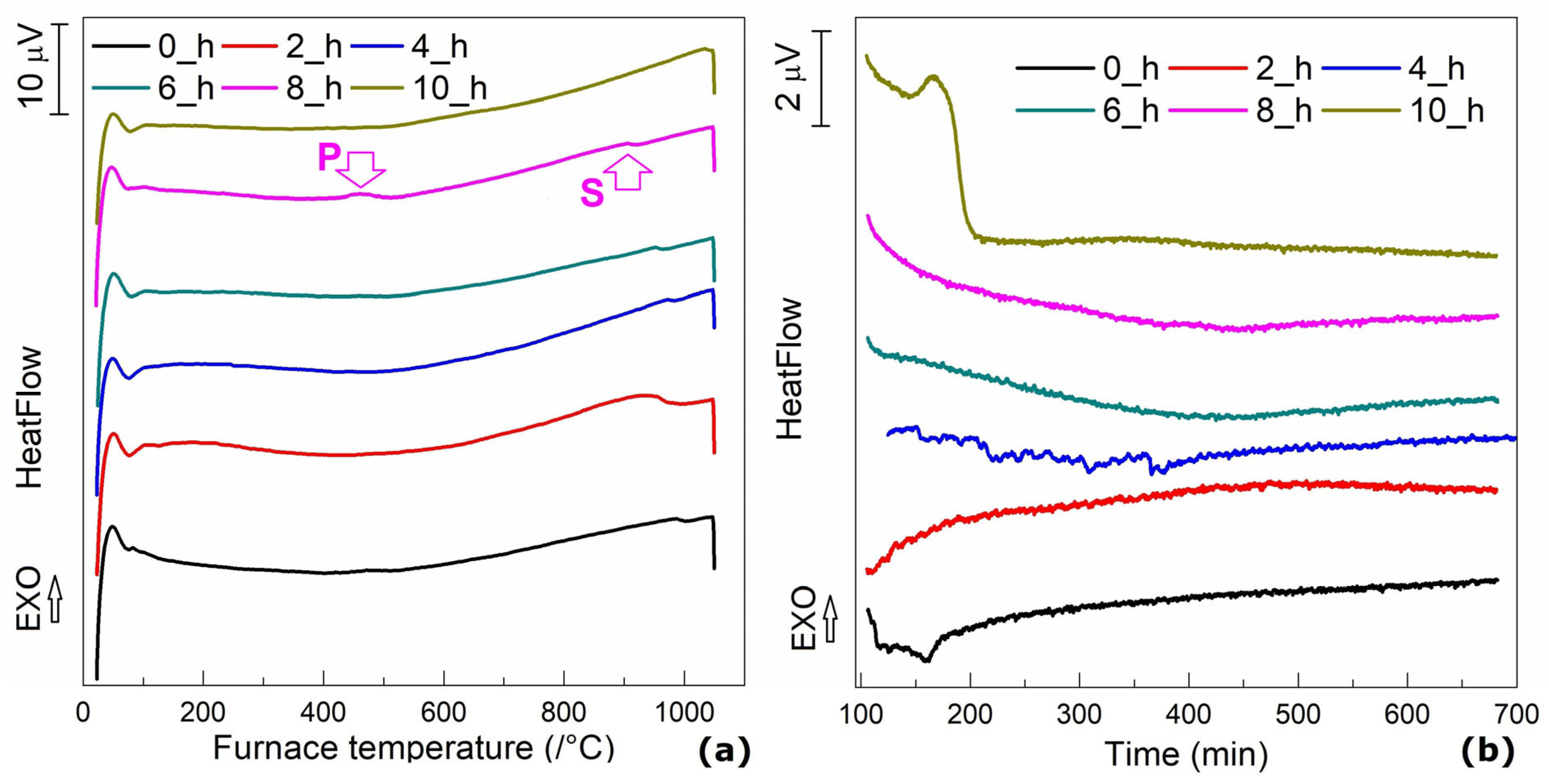
3.1. DSC Evaluation
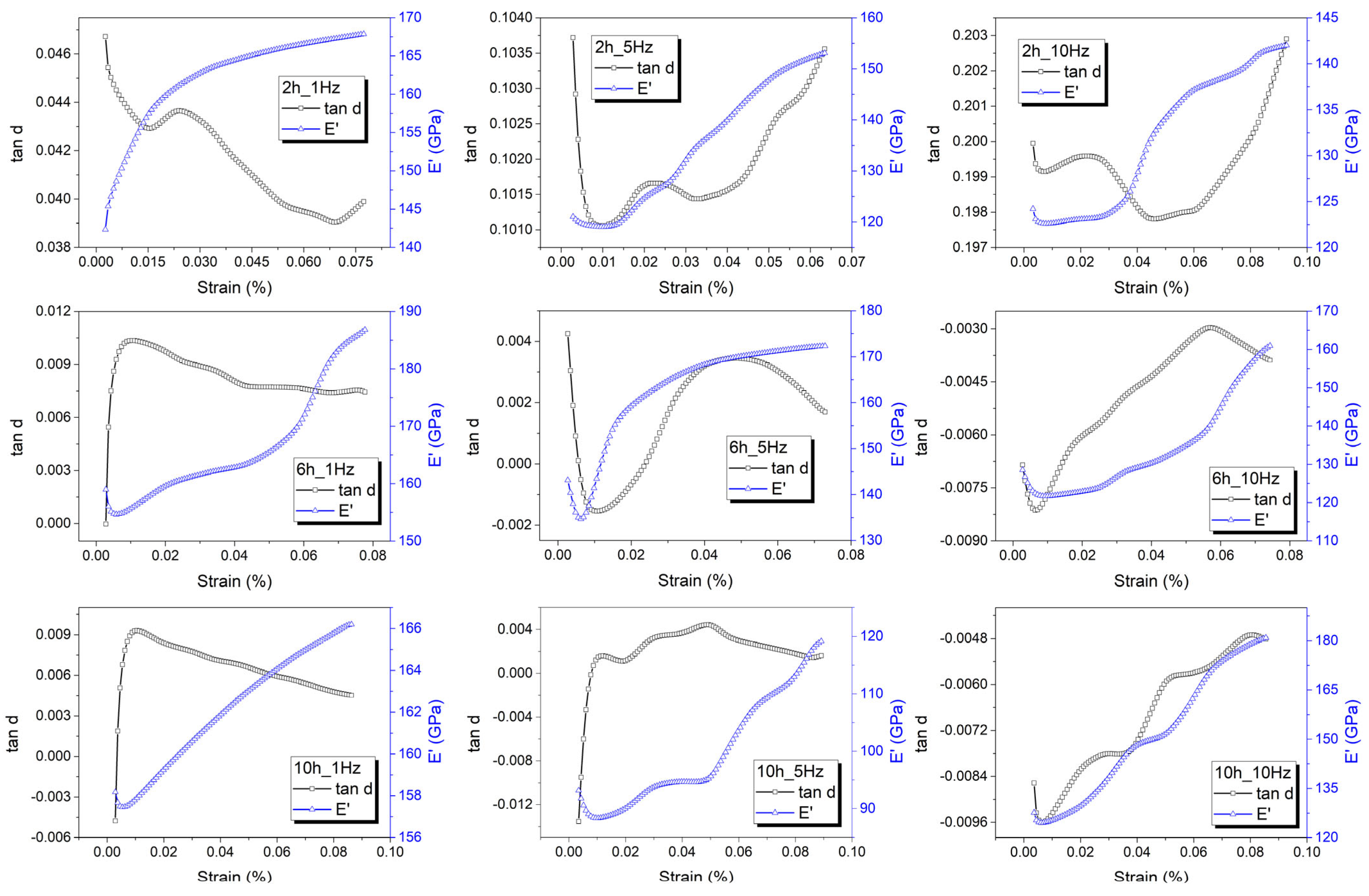
3.2. DMA Evaluation
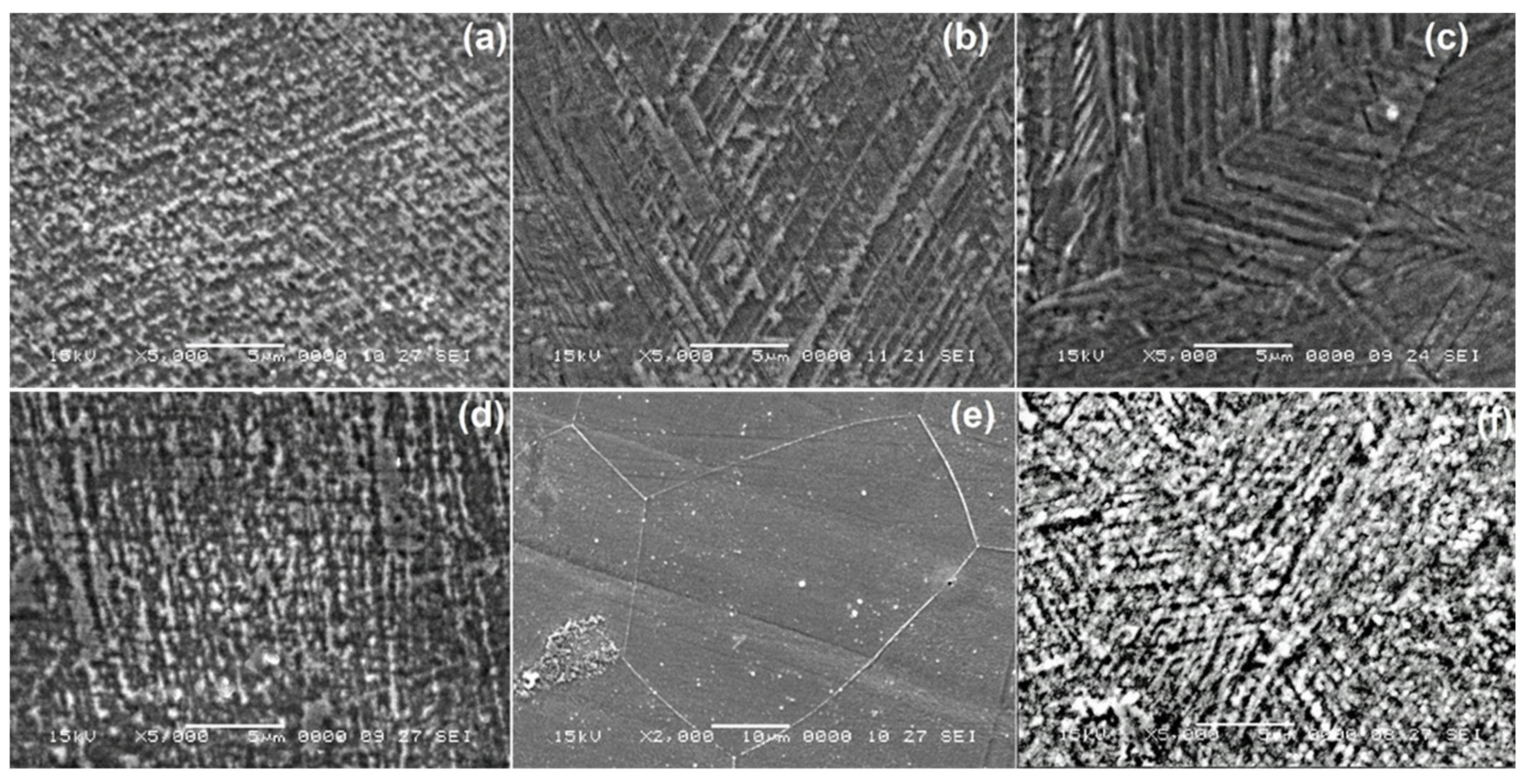
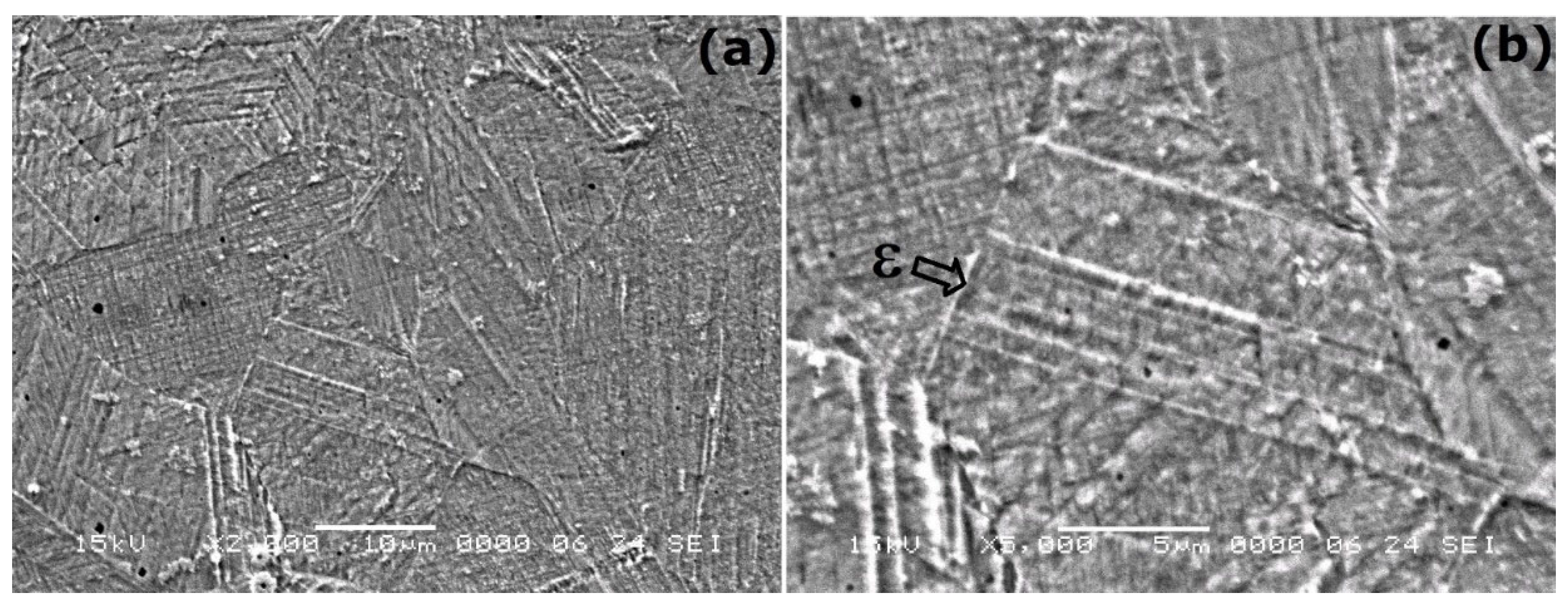
3.3. SEM Investigations
- (i)
- The grain size tends to increase with an increasing holding time due to coalescence enhancement as an effect of minimizing grain boundary energy at the solid–solid interface [28].
- (ii)
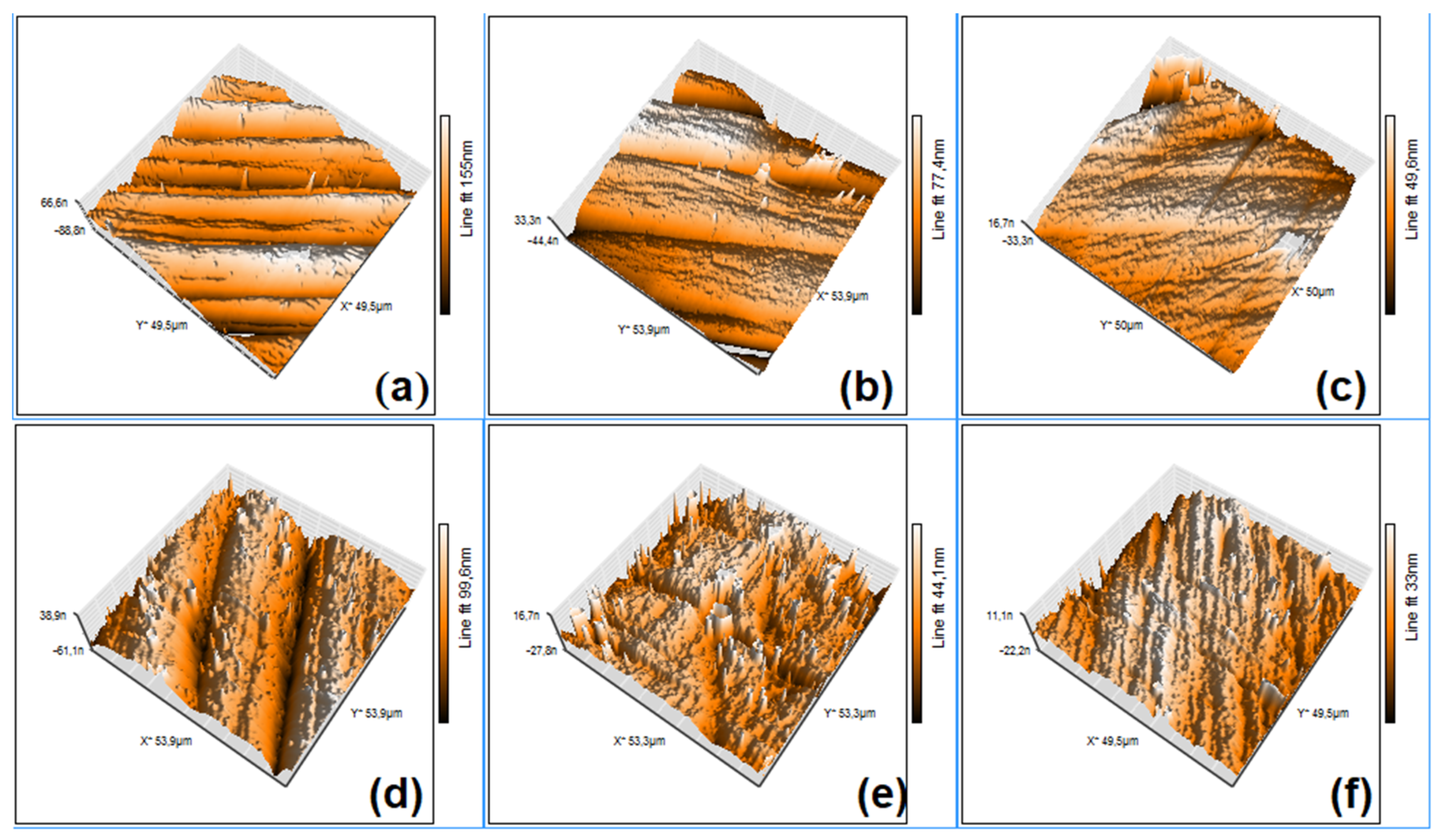
- Stress-induced martensite plates become shorter with increasing the frequency of DMA-SS-3PB. Straight thin plates are visible only at the specimen solutions treated for 2 h (Figure 5a,d,g).
3.4. XRD Investigations
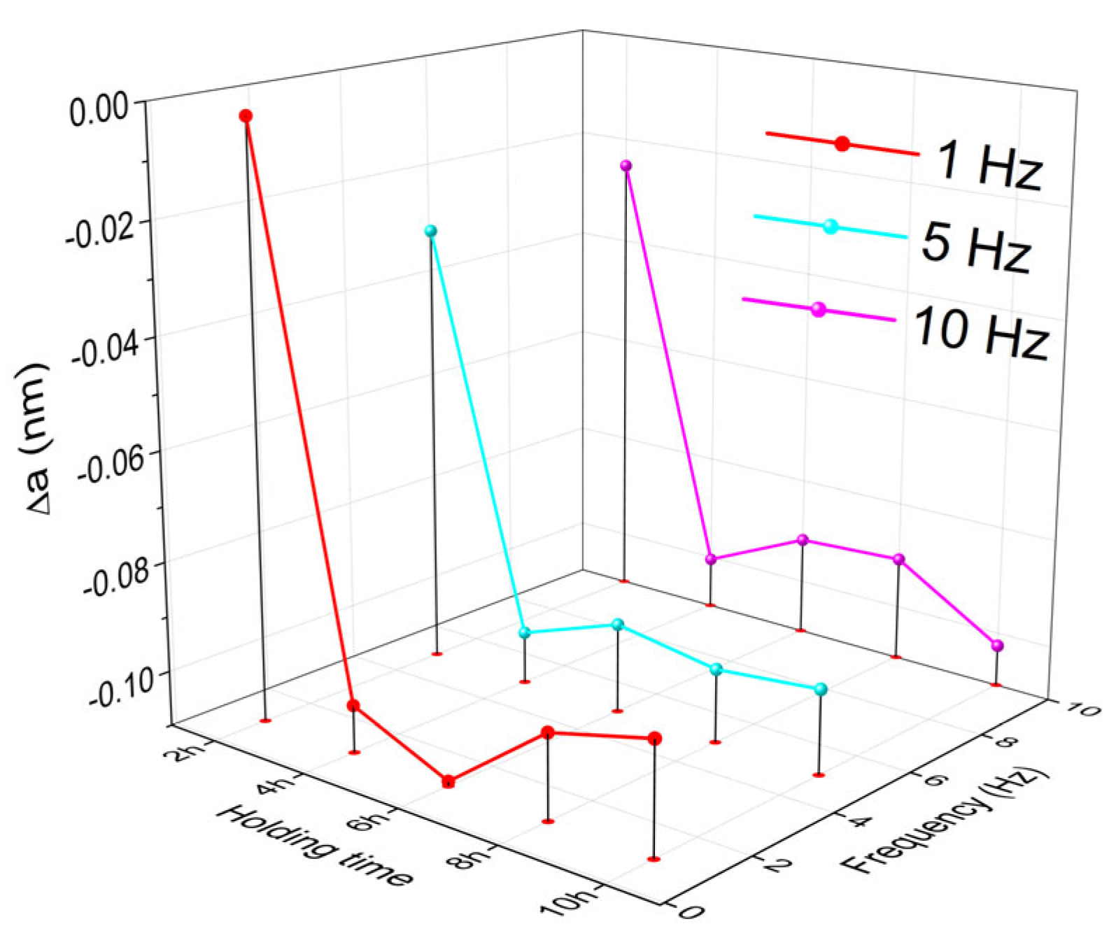
3.5. AFM Observations
4. Discussion
5. Conclusions
- A precipitation phenomenon was identified by DSC in the specimens that were solution-treated for 8 and 10 h;
- Dynamical deformations by RT strain sweeps caused work hardening and a general increase in the storage modulus;
- At the precipitate-free specimens, which were solution-treated for 2 and 4 h, internal friction ranged between 0.1 and 0.2;
- Neither in the initial hot-rolled specimens nor in the specimens that were solution-treated between 6 and 10 h, the martensite plates were not visible on SEM micrographs;
- The application of RT strain sweeps caused the occurrence of stress-induced martensite or the fragmentation of the thermally induced one;
- In solution-treated specimens, the increase in the holding time (from 2 to 10 h) was more effective than the increase in the deformation frequency (from 1 to 10 Hz) in the refinement of martensite plates;
- After 10 h of holding at 1050 °C and the strain sweep application at a frequency of 10 Hz, the martensite plates reached the minimum mean values of their width (659 nm) and height (382 nm) and became preferably oriented;
- The recorded XRD patterns indicated that after the dynamic deformation, most of the microstructure comprises mostly α’-bcc martensite, which was due to the high amount of dynamical deformation induced by the RT strain sweep;
- A holding time increase from 2 to 10 h enhanced the compression of the parameter of the cubic unit cell by approx. 30%, which changed the crystallization system from cubic to tetragonal-centered cubic.
- A new mechanical treatment has been introduced for Fe-Mn-Si-based SMAs, based on RT isothermal dynamic bending, which is able to reinforce the storage modulus and refine the martensitic structure.
Supplementary Materials
Author Contributions
Funding
Data Availability Statement
Conflicts of Interest
References
- Maki, T. Ferrous shape memory alloys. In Shape Memory Materials; Otsuka, K., Wayman, C.M., Eds.; University Press: Cambridge, UK, 1998; pp. 117–132. [Google Scholar]
- Cao, B.; Iwamoto, T. A new method to measure volume resistivity during tension for strain sensitivity deformation and transformation behaviour of Fe28Mn6Si5Cr shape memory alloy. Int. J. Mech. Sci. 2018, 156–157, 445–454. [Google Scholar] [CrossRef]
- Dong, Z.Z.; Kajiwara, S.; Kikuchi, T.; Sawaguchi, T. Effect of pre-deformation at room temperature on shape memory properties of stainless type Fe–15Mn–5Si–9Cr–5Ni–(0.5–1.5)NbC alloys. Acta Mater. 2005, 53, 5009–5018. [Google Scholar] [CrossRef]
- Sato, A.; Chishima, E.; Soma, K.; Mori, T. Shape memory effect in γ↔ε transformation in Fe-30Mn-1Si alloy single crystals. Acta Metall. Mater. 1982, 30, 1177–1183. [Google Scholar] [CrossRef]
- Kajiwara, S. Characteristic features of shape memory effect and related transformation behavior in Fe-based alloys. Mat. Sci. Eng. A 1999, 273–275, 67–88. [Google Scholar] [CrossRef]
- Arruda, G.J.; Buono, V.T.L.; Andrade, M.S. The influence of deformation on the microstructure and transformation temperatures of Fe–Mn–Si–Cr–Ni shape memory alloys. Mater. Sci. Eng. A 1999, 273–275, 528–532. [Google Scholar] [CrossRef]
- Otsuka, H.; Yamada, H.; Maruyama, T.; Tanahashi, H.; Matsuda, S.; Murakami, M. Effects of alloying additions on Fe-Mn-Si shape memory alloys. ISIJ Int. 1990, 30, 675–679. [Google Scholar] [CrossRef] [Green Version]
- Kajiwara, S.; Baruj, A.; Kikuchi, T.; Shinya, N. Low-cost high-quality Fe-based shape memory alloys suitable for pipe joints. In Smart Structures and Materials; Lagoudas, D.C., Ed.; SPIE: Bellingham, WA, USA, 2003; Volume 5053, pp. 250–261. [Google Scholar]
- Farjami, S.; Hiraga, K.; Kubo, H. Shape memory effect and crystallographic investigation in VN containing Fe-Mn-Si-Cr alloys. Mater. Trans. 2005, 55, 930–935. [Google Scholar] [CrossRef] [Green Version]
- Maruyama, T.; Kurita, T.; Kozaki, S.; Andou, K.; Farjami, S.; Kubo, H. Innovation in producing crane rail fishplate using Fe-Mn-Si-Cr based shape memory alloy. Mater. Sci. Technol. 2008, 25, 908–912. [Google Scholar] [CrossRef]
- Sawaguchi, T.; Kikuchi, T.; Ogawa, K.; Yin, F.X.; Kajiwara, S.; Kushibe, A.; Ogawa, T. Internal Friction of Fe-Mn-Si-Based Shape Memory Alloys Containing Nb and C and Their Application as a Seismic Damping Material. Key Eng. Mater. 2006, 319, 53–58. [Google Scholar] [CrossRef]
- Paleu, V.; Gurău, G.; Comăneci, R.I.; Sampath, V.; Gurău, C.; Bujoreanu, L.G. A new application of Fe-28Mn-6Si-5Cr (mass%) shape memory alloy, for self-adjustable axial preloading of ball bearings. Smart Mater. Struct. 2018, 27, 075026. [Google Scholar] [CrossRef]
- Sawaguchi, T.; Sahu, P.; Kikuchi, T.; Ogawa, K.; Kajiwara, S.; Kushibe, A.; Higashino, M.; Ogawa, T. Vibration mitigation by the reversible fcc/hcp martensitic transformation during cyclic tension–compression loading of an Fe–Mn–Si-based shape memory alloy. Scripta Mater. 2006, 55, 1885–1890. [Google Scholar] [CrossRef]
- Bidaux, J.-E.; Schaller, R.; Benoit, W. Study of hcp-fcc phase transition in Cobalt by acoustic measurements. Acta Metall. 1989, 37, 803–811. [Google Scholar] [CrossRef]
- De, A.K.; Cabanas, N.; De Cooman, B.C. Fcc-hcp Transformation-Related Internal Friction in Fe-Mn Alloys. Int. J. Mater. Res. 2002, 93, 228–235. [Google Scholar] [CrossRef]
- Van Humbeeck, J.; Stoiber, J.; Delaey, L.; Gotthardt, R. The high damping capacity of shape-memory alloys. Int. J. Mater. Res. 1995, 86, 176–183. [Google Scholar] [CrossRef]
- Wetton, R.E. Thermomechanical methods. In Handbook of Thermal Analysis and Calorimetry; Brown, M.E., Ed.; Principles and Practice; Elsevier Science: Amsterdam, The Neverlands, 1998; Volume 1, pp. 363–399. [Google Scholar]
- Bulbuc, V.; Pricop, B.; Maxim, F.; Popa, M.; Cimpoesu, N.; Bujoreanu, L.G. Influence of dynamic three point bending on the work hardening capacity of T105Mn120 manganese steel. J. Mater. Eng. Perform. 2018, 27, 6127–6135. [Google Scholar] [CrossRef]
- Bulbuc, V.; Pricop, B.; Maxim, F.; Popa, M.; Cimpoesu, N.; Bujoreanu, L.-G. Variation of damping behaviour of T105Mn120 castings, used for railway safety systems, as an effect of extreme loading conditions. Mater. Today Proc. 2019, 19, 949–955. [Google Scholar] [CrossRef]
- Chung, C.Y.; Chen, S.; Hsu, T.Y. Thermomechanical training behavior and its dynamic mechanical analysis in an Fe-Mn-Si shape memory alloy. Mater. Char. 1996, 37, 227–236. [Google Scholar] [CrossRef]
- Dong, Z.Z.; Sawaguchi, T.; Kikuchi, T.; Yin, F.; Ogawa, K.; Sahu, P.; Kajiwara, S. Internal friction study on fcc/hcp martensitic transformations in thermomechanically treated Fe–28Mn–6Si–5Cr–0.53Nb–0.06C (mass%) alloys. Mater. Sci. Eng. A. 2006, 552, 505–508. [Google Scholar] [CrossRef]
- Popa, M.; Pricop, B.; Mihalache, E.; Bujoreanu, L.G. Storage modulus and internal friction variations in a Fe-28Mn-6Si-5Cr (mass. %) shape memory alloy analyzed by three point-bending DMA. IOP Conf. Series Mater. Sci. Eng. 2017, 227, 012099. [Google Scholar] [CrossRef] [Green Version]
- Popa, M.; Lohan, N.-M.; Popa, F.; Pricop, B.; Bujoreanu, L.-G. Holding-temperature effects on thermally and stress induced martensitic transformations in an FeMnSiCr SMA. Mater. Today: Proc. 2019, 19, 956–962. [Google Scholar] [CrossRef]
- Tasaki, W.; Sawaguchi, T.; Tsuchiya, K. EBSD analysis of dual γ/ε phase microstructures in tensile-deformed Fe-Mn-Si shape memory alloy. J. Alloy. Compd. 2019, 797, 529–536. [Google Scholar] [CrossRef]
- Suru, M.G.; Bujoreanu, L.-G. Comparative topographic study of surface micro-relief of primary martensite plates in shape memory alloys with different crystalline structures. Mat.-Wiss. U. Werkstofftech. 2012, 53, 973–978. [Google Scholar] [CrossRef]
- Zlá, S.; Smetana, B.; Žaludová, M.; Dobrovská, J.; Vodárek, V.; Konečná, K.; Matějka, V.; Francová, H. Determination of thermophysical properties of high temperature alloy IN713LC by thermal analysis. J. Therm. Anal. Calorim. 2012, 110, 211–219. [Google Scholar] [CrossRef] [Green Version]
- Sawaguchi, T.; Bujoreanu, L.G.; Kikuchi, T.; Ogawa, K.; Yin, F. Effects of Nb and C in solution and in NbC form on the transformation-related internal friction of Fe–17Mn (mass%) alloys. ISIJ Int. 2008, 58, 99–106. [Google Scholar] [CrossRef]
- Han, C.; Jiang, P.; Geng, S.; Gao, S.; Mi, G.; Wang, C. Multiphase-field simulation of grain coalescence behavior and its effectson solidification cracking susceptibility during welding of Al-Cu alloys. Mater. Design 2021, 211, 1101561. [Google Scholar] [CrossRef]
- Yang, Y.; Leinenbach, C.; Shahverdi, M. Simulation and experimental characterization of VC precipitation and recovery stress formation in an FeMnSi-based shape memory alloy. J. Alloy. Comp. 2023, 950, 168856. [Google Scholar] [CrossRef]
- Cullity, B.D. Elements of X-ray Diffraction; Addison-Wesley Publishing Company: Boston, MA, USA, 1956; pp. 37–52. [Google Scholar]
- Sawaguchi, T.; Bujoreanu, L.G.; Kikuchi, T.; Ogawa, K.; Koyama, M.; Murakami, M. Mechanism of reversible transformation-induced plasticity of Fe–Mn–Si shape memory alloys. Scripta Mater. 2008, 59, 826–829. [Google Scholar] [CrossRef]


| Specimen | Plate Group No. | Plate No. | Dimension | Average Value | Standard Deviation | Specimen | Plate Group No. | Plate No. | Dimension | Average Value | Standard Deviation |
|---|---|---|---|---|---|---|---|---|---|---|---|
| 2 h–1 Hz | 1 | 1 | w11 | 16,244 | 770.2 | 2 h–10 Hz | 1 | 1 | w11 | 791 | 89.3 |
| h11 | 8639 | 675.8 | h11 | 571 | 147 | ||||||
| 2 | w12 | 19,184 | 582.9 | 2 | w12 | 626 | 66.1 | ||||
| h12 | 11,404 | 463.4 | h12 | 458 | 106.3 | ||||||
| 3 | w13 | 7376 | 800.7 | 3 | w13 | 3037 | 353.6 | ||||
| h13 | 4174 | 585 | h13 | 1803 | 369.6 | ||||||
| 4 | w14 | 6797 | 2997.5 | 4 | w14 | 446 | 46.4 | ||||
| h14 | 4856 | 699.6 | h14 | 278 | 19.4 | ||||||
| 5 | w15 | 5538 | 470.7 | 5 | w15 | 597 | 120.8 | ||||
| h15 | 3921 | 344.2 | h15 | 264 | 74.6 | ||||||
| 2 | 1 | w21 | 4795 | 431.4 | 2 | 1 | w21 | 686 | 140.2 | ||
| h21 | 2798 | 219.3 | h21 | 404 | 133.7 | ||||||
| 2 | w22 | 4776 | 128.3 | 2 | w22 | 687 | 111.4 | ||||
| h22 | 2972 | 216.2 | h22 | 437 | 107.4 | ||||||
| 3 | w23 | 4961 | 350.8 | 3 | w23 | 837 | 123.9 | ||||
| h23 | 3478 | 455.2 | h23 | 462 | 50.1 | ||||||
| 4 | w24 | 2225 | 258.6 | 4 | w24 | 8173 | 1257.5 | ||||
| h24 | 1267 | 275.6 | h24 | 6040 | 898.9 | ||||||
| 5 | w25 | 11,878 | 794.5 | 5 | w25 | 13,300 | 645.9 | ||||
| h25 | 7030 | 641.9 | h25 | 7539 | 852.5 | ||||||
| 3 | 1 | w31 | 14,440 | 460.4 | 3 | 1 | w31 | 10,412 | 820.7 | ||
| h31 | 8279 | 721 | h31 | 6912 | 603.3 | ||||||
| 2 | w32 | 6519 | 435.5 | 2 | w32 | 11,463 | 2182.3 | ||||
| h32 | 4303 | 571.7 | h32 | 6475 | 658.2 | ||||||
| 3 | w33 | 2302 | 345.1 | 3 | w33 | 669 | 247.7 | ||||
| h33 | 1696 | 102.4 | h33 | 432 | 168.6 | ||||||
| 4 | w34 | 6403 | 510.7 | 4 | w34 | 661 | 122.9 | ||||
| h34 | 3960 | 89 | h34 | 288 | 72.4 | ||||||
| 5 | w35 | 7784 | 306.6 | 5 | w35 | 544 | 69.9 | ||||
| h35 | 3852 | 262.2 | h35 | 369 | 55.6 | ||||||
| 4 | 1 | w41 | 9855 | 534.8 | 4 | 1 | w41 | 738 | 243.7 | ||
| h41 | 5458 | 648.7 | h41 | 475 | 184.1 | ||||||
| 2 | w42 | 4131 | 272 | 2 | w42 | 606 | 187.7 | ||||
| h42 | 3237 | 287.3 | h42 | 366 | 127.4 | ||||||
| 3 | w43 | 3764 | 420.4 | 3 | w43 | 563 | 194.1 | ||||
| h43 | 4041 | 949.4 | h43 | 335 | 193.1 | ||||||
| 4 | w44 | 6286 | 421.4 | 4 | w44 | 397 | 54.4 | ||||
| h44 | 3700 | 372.3 | h44 | 237 | 47.6 | ||||||
| 5 | w45 | 10,320 | 264 | 5 | w45 | 328 | 86.4 | ||||
| h45 | 5889 | 254 | h45 | 264 | 77.3 | ||||||
| 5 | 1 | w51 | 7146 | 674.9 | 5 | 1 | w51 | 399 | 84.6 | ||
| h51 | 394 | 422.2 | h51 | 218 | 22.9 | ||||||
| 2 | w52 | 4085 | 240.7 | 2 | w52 | 340 | 68.3 | ||||
| h52 | 3456 | 188.6 | h52 | 221 | 27.6 | ||||||
| 3 | w53 | 4066 | 531.2 | 3 | w53 | 432 | 60.5 | ||||
| h53 | 2574 | 1312.5 | h53 | 254 | 64 | ||||||
| 4 | w54 | 2361 | 206.6 | 4 | w54 | 448 | 57.7 | ||||
| h54 | 1891 | 160.5 | h54 | 230 | 39.4 | ||||||
| 5 | w55 | 3631 | 318.7 | 5 | w55 | 660 | 40.5 | ||||
| h55 | 2245 | 251.3 | h55 | 311 | 47.3 | ||||||
| 10 h–1 Hz | 1 | 1 | w11 | 6355 | 1265.5 | 10 h–10 Hz | 1 | 1 | w11 | 848 | 128.6 |
| h11 | 4225 | 166.5 | h11 | 505 | 106.4 | ||||||
| 2 | w12 | 3896 | 440.7 | 2 | w12 | 939 | 73 | ||||
| h12 | 2574 | 181.8 | h12 | 454 | 49 | ||||||
| 3 | w13 | 2999 | 516.8 | 3 | w13 | 713 | 96.6 | ||||
| h13 | 1608 | 169.6 | h13 | 937 | 61 | ||||||
| 4 | w14 | 2460 | 320.9 | 4 | w14 | 744 | 66 | ||||
| h14 | 1732 | 225.8 | h14 | 476 | 24.2 | ||||||
| 5 | w15 | 2529 | 480.5 | 5 | w15 | 859 | 42.7 | ||||
| h15 | 1432 | 311.4 | h15 | 480 | 28.7 | ||||||
| 2 | 1 | w21 | 3665 | 361.4 | 2 | 1 | w21 | 673 | 13.2 | ||
| h21 | 2801 | 70.8 | h21 | 381 | 53.2 | ||||||
| 2 | w22 | 3056 | 210.1 | 2 | w22 | 658 | 82.5 | ||||
| h22 | 2273 | 187.9 | h22 | 391 | 32 | ||||||
| 3 | w23 | 1059 | 55.8 | 3 | w23 | 737 | 82 | ||||
| h23 | 526 | 54 | h23 | 402 | 40.1 | ||||||
| 4 | w24 | 983 | 57.5 | 4 | w24 | 999 | 127.2 | ||||
| h24 | 501 | 66.8 | h24 | 516 | 85.2 | ||||||
| 5 | w25 | 763 | 81.9 | 5 | w25 | 842 | 100.3 | ||||
| h25 | 433 | 49.7 | h25 | 485 | 65.6 | ||||||
| 3 | 1 | w31 | 620 | 185.9 | 3 | 1 | w31 | 695 | 40.5 | ||
| h31 | 380 | 118.5 | h31 | 429 | 28.8 | ||||||
| 2 | w32 | 694 | 74.4 | 2 | w32 | 694 | 66 | ||||
| h32 | 416 | 25.5 | h32 | 430 | 30.4 | ||||||
| 3 | w33 | 619 | 88.9 | 3 | w33 | 808 | 80.5 | ||||
| h33 | 361 | 47 | h33 | 527 | 101.9 | ||||||
| 4 | w34 | 740 | 72 | 4 | w34 | 782 | 22.6 | ||||
| h34 | 381 | 39.5 | h34 | 417 | 28.5 | ||||||
| 5 | w35 | 866 | 80.6 | 5 | w35 | 664 | 140.1 | ||||
| h35 | 471 | 43.8 | h35 | 327 | 73.3 | ||||||
| 4 | 1 | w41 | 791 | 49.5 | 4 | 1 | w41 | 327 | 24.8 | ||
| h41 | 428 | 50 | h41 | 188 | 24.7 | ||||||
| 2 | w42 | 936 | 48.7 | 2 | w42 | 350 | 37.5 | ||||
| h42 | 466 | 41.5 | h42 | 194 | 22.4 | ||||||
| 3 | w43 | 2032 | 110.2 | 3 | w43 | 824 | 210 | ||||
| h43 | 1044 | 57 | h43 | 387 | 65.9 | ||||||
| 4 | w44 | 798 | 166.3 | 4 | w44 | 706 | 31.1 | ||||
| h44 | 533 | 146.8 | h44 | 336 | 41.5 | ||||||
| 5 | w45 | 1779 | 150.6 | 5 | w45 | 707 | 57.1 | ||||
| h45 | 911 | 90.1 | h45 | 345 | 42.5 | ||||||
| 5 | 1 | w51 | 1235 | 51.4 | 5 | 1 | w51 | 326 | 67.2 | ||
| h51 | 775 | 63.7 | h51 | 144 | 20 | ||||||
| 2 | w52 | 1118 | 169.6 | 2 | w52 | 311 | 52.1 | ||||
| h52 | 687 | 61.2 | h52 | 188 | 42.3 | ||||||
| 3 | w53 | 948 | 94.3 | 3 | w53 | 714 | 34.9 | ||||
| h53 | 524 | 37.4 | h53 | 339 | 20.7 | ||||||
| 4 | w54 | 884 | 50.1 | 4 | w54 | 870 | 54.6 | ||||
| h54 | 518 | 59.3 | h54 | 395 | 57.7 | ||||||
| 5 | w55 | 665 | 65.8 | 5 | w55 | 340 | 74.4 | ||||
| h55 | 406 | 23.9 | h55 | 177 | 40 |
| Specimen | 2 h–1 Hz | 2 h–10 Hz | 10 h–1 Hz | 10 h–10 Hz |
|---|---|---|---|---|
| wmean | 6913 | 2298 | 1664 | 659 |
| hmean | 4119 | 1417 | 1037 | 382 |
Disclaimer/Publisher’s Note: The statements, opinions and data contained in all publications are solely those of the individual author(s) and contributor(s) and not of MDPI and/or the editor(s). MDPI and/or the editor(s) disclaim responsibility for any injury to people or property resulting from any ideas, methods, instructions or products referred to in the content. |
© 2023 by the authors. Licensee MDPI, Basel, Switzerland. This article is an open access article distributed under the terms and conditions of the Creative Commons Attribution (CC BY) license (https://creativecommons.org/licenses/by/4.0/).
Share and Cite
Popa, M.; Popa, F.; Pricop, B.; Cimpoeșu, N.; Lohan, N.-M.; Kicsi, G.; Istrate, B.; Bujoreanu, L.-G. Heat Treatment and Dynamic Mechanical Analysis Strain Sweep Effects on the Phase Structure and Morphology of an Fe-28Mn-6Si-5Cr Shape Memory Alloy. Nanomaterials 2023, 13, 1250. https://doi.org/10.3390/nano13071250
Popa M, Popa F, Pricop B, Cimpoeșu N, Lohan N-M, Kicsi G, Istrate B, Bujoreanu L-G. Heat Treatment and Dynamic Mechanical Analysis Strain Sweep Effects on the Phase Structure and Morphology of an Fe-28Mn-6Si-5Cr Shape Memory Alloy. Nanomaterials. 2023; 13(7):1250. https://doi.org/10.3390/nano13071250
Chicago/Turabian StylePopa, Mihai, Florin Popa, Bogdan Pricop, Nicanor Cimpoeșu, Nicoleta-Monica Lohan, Gabriel Kicsi, Bogdan Istrate, and Leandru-Gheorghe Bujoreanu. 2023. "Heat Treatment and Dynamic Mechanical Analysis Strain Sweep Effects on the Phase Structure and Morphology of an Fe-28Mn-6Si-5Cr Shape Memory Alloy" Nanomaterials 13, no. 7: 1250. https://doi.org/10.3390/nano13071250