
Self-Assembled Monolayer-Based Hole-Transporting Materials for Perovskite Solar Cells


Abstract
1. Introduction
2. SAM-Based HTMs
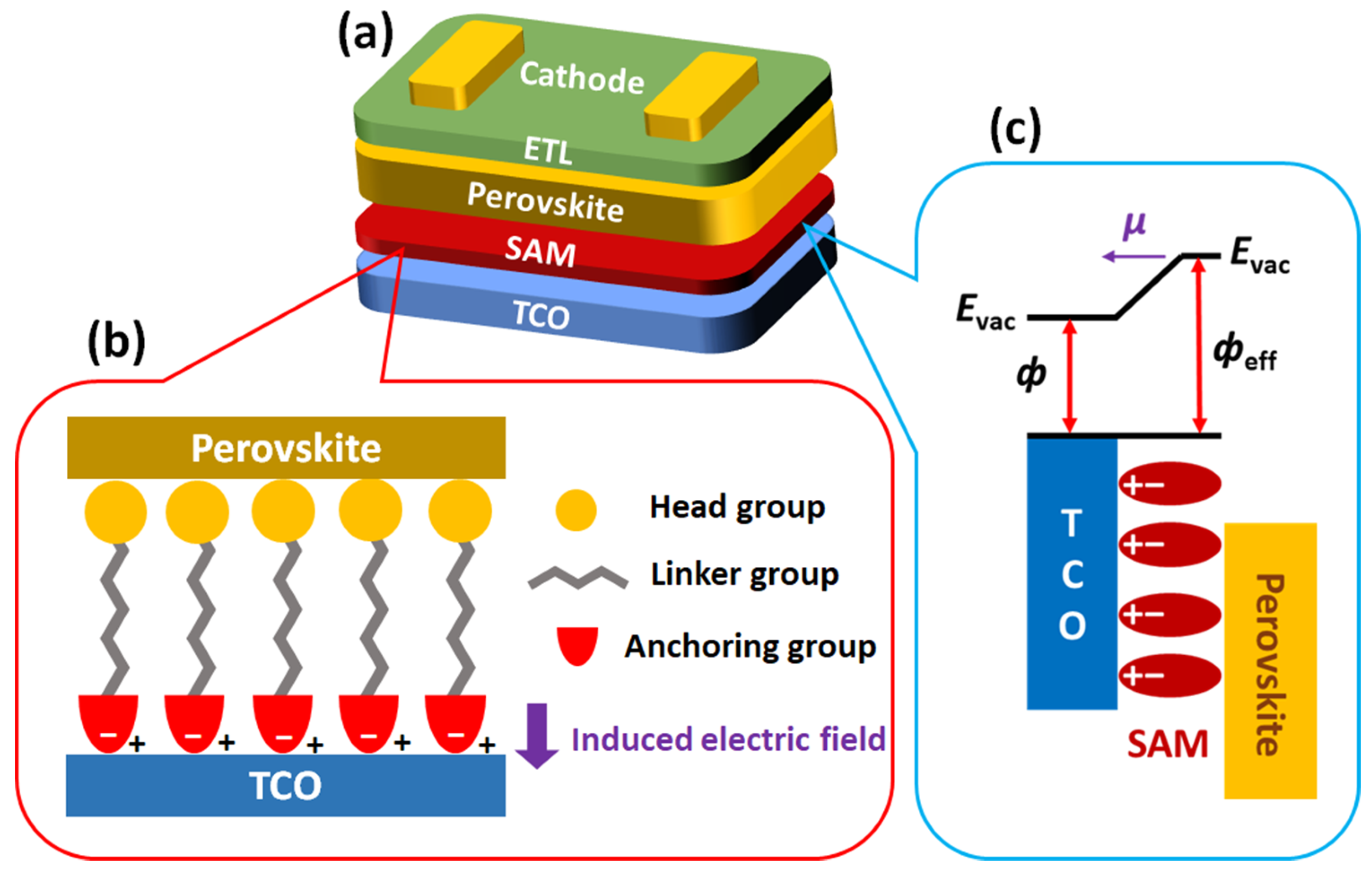
2.1. Structure and Characteristics of SAM-Based HTMs
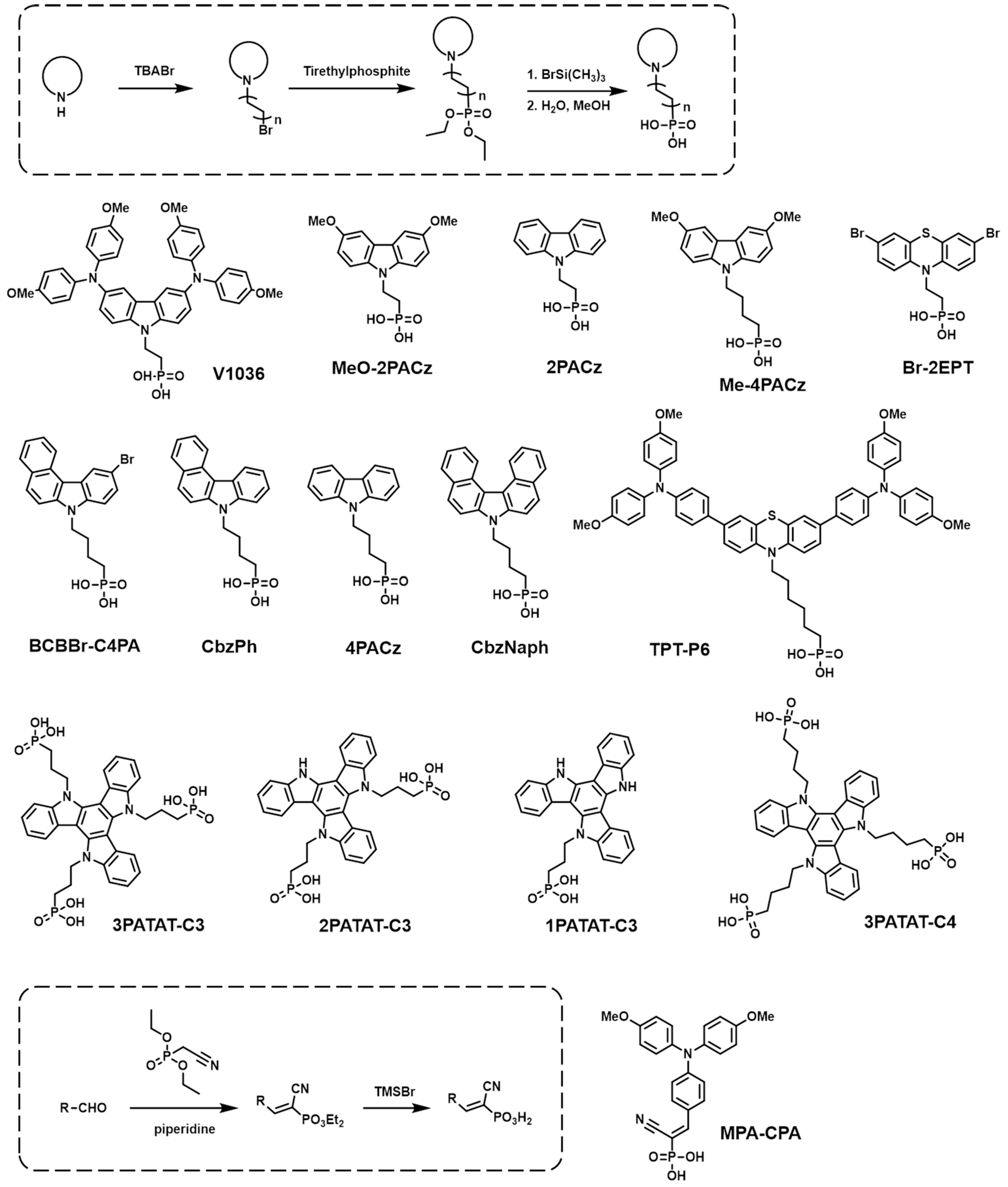
2.2. PA-Based SAMs
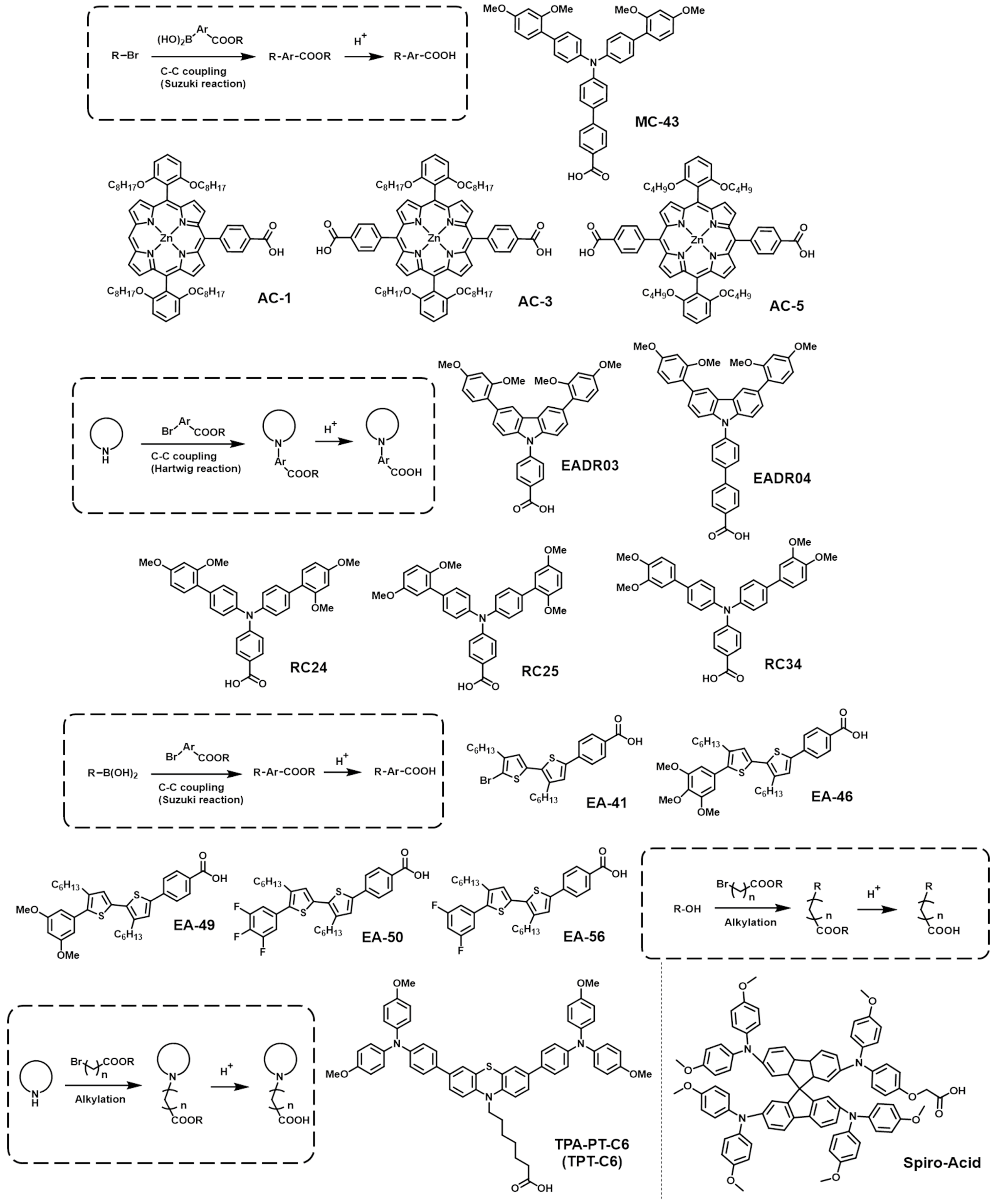
2.3. CA-Based SAMs
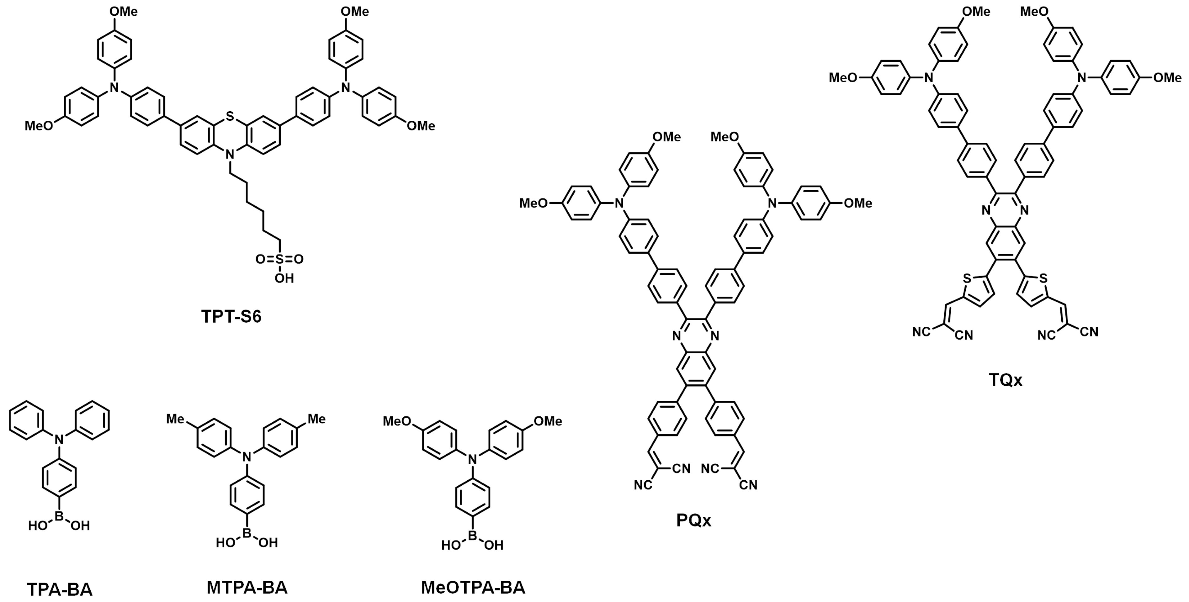
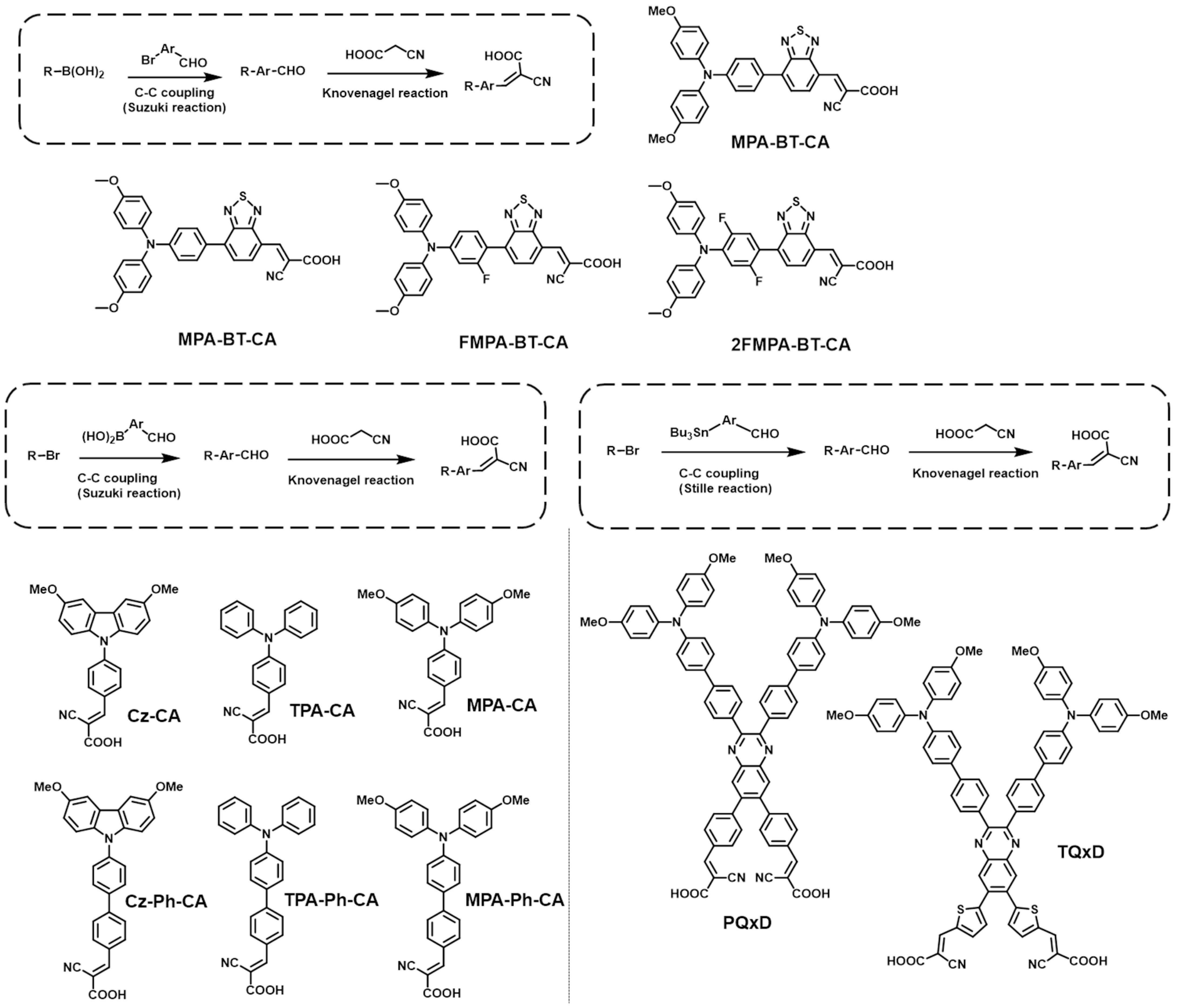
2.4. CAA-Based SAMs

| HTM | Device Structure | VOC [V] | JSC [mA/cm−2] | FF [%] | PCE [%] | Device Stability a | Refs. |
|---|---|---|---|---|---|---|---|
| MPA-BT-CA | ITO/MPA-BT-CA/(FA0.17MA0.94PbI3.11)0.95(PbCl2)0.05/C60/BCP/Ag | 1.13 | 22.25 | 84.8 | 21.24 | 98%, 14 d, RT e,g | [82] |
| MPA-BT-CA | ITO/MPA-BT-CA/(FA0.17MA0.94PbI3.11)0.95(PbCl2)0.05 /C60/BCP/Cu | 1.10 | 22.73 | 82.3 | 20.70 | 67%, 120 h, RT d,g | [84] |
| FMPA-BT-CA | ITO/FMPA-BT-CA/(FA0.17MA0.94PbI3.11)0.95(PbCl2)0.05/C60/BCP/Cu | 1.15 | 23.33 | 83.3 | 22.37 | ≈80%, 120 h, RT d,g | |
| 2FMPA-BT-CA | ITO/2FMPA-BT-CA/(FA0.17MA0.94PbI3.11)0.95(PbCl2)0.05/C60/BCP/Cu | 1.14 | 22.81 | 83.1 | 21.68 | >74%, 120 h, RT d,g | |
| Cz-CA | ITO/Cz-CA/Cs0.05(FA0.92MA0.08)0.95Pb(I0.92Br0.08)3/PCBM/C60/Ag | ~1.06 | ~23.2 | ~83.0 | ~20.0 | - | [85] |
| Cz-Ph-CA | ITO/MPA-Ph-CA/Cs0.05(FA0.92MA0.08)0.95Pb(I0.92Br0.08)3/PCBM/C60/Ag | ~1.11 | ~23.0 | ~83.0 | ~20.2 | - | |
| TPA-CA | ITO/TPA-CA/Cs0.05(FA0.92MA0.08)0.95Pb(I0.92Br0.08)3/PCBM/C60/Ag | ~1.06 | ~22.4 | ~81.0 | ~17.5 | - | |
| TPA-Ph-CA | ITO/TPA-Ph-CA/Cs0.05(FA0.92MA0.08)0.95Pb(I0.92Br0.08)3/PCBM/C60/Ag | ~1.12 | ~23.0 | ~82.5 | ~20.0 | -- | |
| MPA-CA | ITO/MPA-CA/Cs0.05(FA0.92MA0.08)0.95Pb(I0.92Br0.08)3 /PCBM/C60/Ag | ~1.10 | ~23.5 | ~81.0 | ~20.5 | - | |
| MPA-Ph-CA | ITO/MPA-Ph-CA/Cs0.05(FA0.92MA0.08)0.95Pb(I0.92Br0.08)3/PCBM/C60/Ag | 1.139 | 23.55 | 84.02 | 22.53 | 95%, 800 h, 45 °C c,f | |
| PQxD | ITO/PQxD/FASnI3/C60/BCP/Ag | 0.542 | 19.28 | 68.1 | 7.1 | ≈90%,1600 h b,f | [86] |
| TQxD | ITO/TQxD/FASnI3/C60/BCP/Ag | 0.574 | 21.05 | 68.8 | 8.3 | ≈90%,1600 h b,f |
2.5. Other SAMs
3. Conclusions and Outlook
Author Contributions
Funding
Institutional Review Board Statement
Informed Consent Statement
Data Availability Statement
Conflicts of Interest
References
- Zhang, H.; Pfeifer, L.; Zakeeruddin, S.M.; Chu, J.; Grätzel, M. Tailoring passivators for highly efficient and stable perovskite solar cells. Nat. Rev. Chem. 2023, 7, 632–652. [Google Scholar] [CrossRef] [PubMed]
- Park, S.M.; Wei, M.; Xu, J.; Atapattu, H.R.; Eickemeyer, F.T.; Darabi, K.; Grater, L.; Yang, Y.; Liu, C.; Teale, S.; et al. Engineering ligand reactivity enables high-temperature operation of stable perovskite solar cells. Science 2023, 381, 209–215. [Google Scholar] [CrossRef] [PubMed]
- Fakharuddin, A.; Gangishetty, M.K.; Abdi-Jalebi, M.; Chin, S.-H.; bin Mohd Yusoff, A.R.; Congreve, D.N.; Tress, W.; Deschler, F.; Vasilopoulou, M.; Bolink, H.J. Perovskite light-emitting diodes. Nat. Electron. 2022, 5, 203–216. [Google Scholar] [CrossRef]
- Kim, J.S.; Heo, J.-M.; Park, G.-S.; Woo, S.-J.; Cho, C.; Yun, H.J.; Kim, D.-H.; Park, J.; Lee, S.-C.; Park, S.-H.; et al. Ultra-bright, efficient and stable perovskite light-emitting diodes. Nature 2022, 611, 688–694. [Google Scholar] [CrossRef] [PubMed]
- Liu, A.; Zhu, H.; Bai, S.; Reo, Y.; Caironi, M.; Petrozza, A.; Dou, L.; Noh, Y.-Y. High-performance metal halide perovskite transistors. Nat. Electron. 2023, 6, 559–571. [Google Scholar] [CrossRef]
- Lin, C.-F.; Huang, K.-W.; Chen, Y.-T.; Hsueh, S.-L.; Li, M.-H.; Chen, P. Perovskite-Based X-ray Detectors. Nanomaterials 2023, 13, 2024. [Google Scholar] [CrossRef] [PubMed]
- Petrović, M.; Chellappan, V.; Ramakrishna, S. Perovskites: Solar cells & engineering applications—Materials and device developments. Sol. Energy 2015, 122, 678–699. [Google Scholar] [CrossRef]
- Wu, T.; Qin, Z.; Wang, Y.; Wu, Y.; Chen, W.; Zhang, S.; Cai, M.; Dai, S.; Zhang, J.; Liu, J. The main progress of perovskite solar cells in 2020–2021. Nano-Micro Lett. 2021, 13, 152. [Google Scholar] [CrossRef]
- Maafa, I.M. All-inorganic perovskite solar cells: Recent advancements and challenges. Nanomaterials 2022, 12, 1651. [Google Scholar] [CrossRef]
- Jeong, W.; Ha, S.R.; Jang, J.W.; Jeong, M.-K.; Hussain, M.D.W.; Ahn, H.; Choi, H.; Jung, I.H. Simple-Structured Low-Cost Dopant-Free Hole-Transporting Polymers for High-Stability CsPbI2Br Perovskite Solar Cells. ACS Appl. Mater. Interfaces 2022, 14, 13400–13409. [Google Scholar] [CrossRef]
- Paulus, F.; Tyznik, C.; Jurchescu, O.D.; Vaynzof, Y. Switched-On: Progress, Challenges, and Opportunities in Metal Halide Perovskite Transistors. Adv. Funct. Mater. 2021, 31, 2101029. [Google Scholar] [CrossRef]
- Zhang, Y.; Zhao, Z.; Liu, Z.; Tang, A. The Scale Effects of Organometal Halide Perovskites. Nanomaterials 2023, 13, 2935. [Google Scholar] [CrossRef]
- Li, G.; Wang, Y.; Huang, L.; Sun, W. Research Progress of High-Sensitivity Perovskite Photodetectors: A Review of Photodetectors: Noise, Structure, and Materials. ACS Appl. Electron. Mater. 2022, 4, 1485–1505. [Google Scholar] [CrossRef]
- Lu, X.; Li, J.; Zhang, Y.; Han, Z.; He, Z.; Zou, Y.; Xu, X. Recent progress on perovskite photodetectors for narrowband detection. Adv. Photonics Res. 2022, 3, 2100335. [Google Scholar] [CrossRef]
- Yang, T.; Gao, L.; Lu, J.; Ma, C.; Du, Y.; Wang, P.; Ding, Z.; Wang, S.; Xu, P.; Liu, D.; et al. One-stone-for-two-birds strategy to attain beyond 25% perovskite solar cells. Nat. Commun. 2023, 14, 839. [Google Scholar] [CrossRef] [PubMed]
- Correa-Baena, J.-P.; Saliba, M.; Buonassisi, T.; Grätzel, M.; Abate, A.; Tress, W.; Hagfeldt, A. Promises and challenges of perovskite solar cells. Science 2017, 358, 739–744. [Google Scholar] [CrossRef]
- Kim, J.Y.; Lee, J.-W.; Jung, H.S.; Shin, H.; Park, N.-G. High-Efficiency Perovskite Solar Cells. Chem. Rev. 2020, 120, 7867–7918. [Google Scholar] [CrossRef]
- Sabbah, H.; Arayro, J.; Mezher, R. Simulation and Investigation of 26% Efficient and Robust Inverted Planar Perovskite Solar Cells Based on GA0.2FA0.78SnI3-1%EDAI2 Films. Nanomaterials 2022, 12, 3885. [Google Scholar] [CrossRef]
- Li, H.; Zhang, W. Perovskite Tandem Solar Cells: From Fundamentals to Commercial Deployment. Chem. Rev. 2020, 120, 9835–9950. [Google Scholar] [CrossRef]
- Wu, X.; Li, B.; Zhu, Z.; Chueh, C.-C.; Jen, A.K.Y. Designs from single junctions, heterojunctions to multijunctions for high-performance perovskite solar cells. Chem. Soc. Rev. 2021, 50, 13090–13128. [Google Scholar] [CrossRef]
- Ašmontas, S.; Mujahid, M. Recent Progress in Perovskite Tandem Solar Cells. Nanomaterials 2023, 13, 1886. [Google Scholar] [CrossRef]
- Patil, P.; Sangale, S.S.; Kwon, S.-N.; Na, S.-I. Innovative Approaches to Semi-Transparent Perovskite Solar Cells. Nanomaterials 2023, 13, 1084. [Google Scholar] [CrossRef]
- Lye, Y.-E.; Chan, K.-Y.; Ng, Z.-N. A Review on the Progress, Challenges, and Performances of Tin-Based Perovskite Solar Cells. Nanomaterials 2023, 13, 585. [Google Scholar] [CrossRef]
- Isikgor, F.H.; Zhumagali, S.T.; Merino, L.V.; De Bastiani, M.; McCulloch, I.; De Wolf, S. Molecular engineering of contact interfaces for high-performance perovskite solar cells. Nat. Rev. Mater. 2023, 8, 89–108. [Google Scholar] [CrossRef]
- Kojima, A.; Teshima, K.; Shirai, Y.; Miyasaka, T. Organometal halide perovskites as visible-light sensitizers for photovoltaic cells. J. Am. Chem. Soc. 2009, 131, 6050–6051. [Google Scholar] [CrossRef]
- Chi, W.; Banerjee, S.K. Stability Improvement of Perovskite Solar Cells by Compositional and Interfacial Engineering. Chem. Mater. 2021, 33, 1540–1570. [Google Scholar] [CrossRef]
- Azmi, R.; Lee, C.L.; Jung, I.H.; Jang, S.Y. Simultaneous improvement in efficiency and stability of low-temperature-processed perovskite solar cells by interfacial control. Adv. Energy Mater. 2018, 8, 1702934. [Google Scholar] [CrossRef]
- Ashiri, R. Highly-transparent Perovskite Thin Films Obtained by a Wet Chemical Processing Method. Non-Met. Mater. Sci. 2019, 1, 22–27. [Google Scholar] [CrossRef]
- AlZoubi, T.; Mourched, B.; Al Gharram, M.; Makhadmeh, G.; Abu Noqta, O. Improving Photovoltaic Performance of Hybrid Organic-Inorganic MAGeI3 Perovskite Solar Cells via Numerical Optimization of Carrier Transport Materials (HTLs/ETLs). Nanomaterials 2023, 13, 2221. [Google Scholar] [CrossRef]
- Liu, H.; Xiang, L.; Gao, P.; Wang, D.; Yang, J.; Chen, X.; Li, S.; Shi, Y.; Gao, F.; Zhang, Y. Improvement strategies for stability and efficiency of perovskite solar cells. Nanomaterials 2022, 12, 3295. [Google Scholar] [CrossRef]
- Jeong, M.-K.; Kang, J.; Park, D.; Yim, S.; Jung, I.H. A conjugated polyelectrolyte interfacial modifier for high performance near-infrared quantum-dot photodetectors. J. Mater. Chem. C 2020, 8, 2542–2550. [Google Scholar] [CrossRef]
- Azmi, R.; Lee, U.-H.; Wibowo, F.T.A.; Eom, S.H.; Yoon, S.C.; Jang, S.-Y.; Jung, I.H. Performance improvement in low-temperature-processed perovskite solar cells by molecular engineering of porphyrin-based hole transport materials. ACS Appl. Mater. Interfaces 2018, 10, 35404–35410. [Google Scholar] [CrossRef]
- Lee, U.H.; Azmi, R.; Sinaga, S.; Hwang, S.; Eom, S.H.; Kim, T.W.; Yoon, S.C.; Jang, S.Y.; Jung, I.H. Diphenyl-2-pyridylamine-Substituted Porphyrins as Hole-Transporting Materials for Perovskite Solar Cells. ChemSusChem 2017, 10, 3780–3787. [Google Scholar] [CrossRef]
- Azmi, R.; Nam, S.Y.; Sinaga, S.; Akbar, Z.A.; Lee, C.-L.; Yoon, S.C.; Jung, I.H.; Jang, S.-Y. High-performance dopant-free conjugated small molecule-based hole-transport materials for perovskite solar cells. Nano Energy 2018, 44, 191–198. [Google Scholar] [CrossRef]
- Wali, Q.; Iftikhar, F.J.; Khan, M.E.; Balilonda, A.; Aamir, M.; Fan, W.; Yang, S. High efficiency (>20%) and stable inverted perovskite solar cells: Current progress and future challenges. J. Mater. Chem. C 2022, 10, 12908–12928. [Google Scholar] [CrossRef]
- Xu, L.; Li, Y.; Zhang, C.; Liu, Y.; Zheng, C.; Lv, W.; Li, M.; Chen, Y.; Huang, W.; Chen, R. Improving the efficiency and stability of inverted perovskite solar cells by CuSCN-doped PEDOT: PSS. Sol. Energy Mater. Sol. Cells 2020, 206, 110316. [Google Scholar] [CrossRef]
- Yu, Z.; Sun, L. Inorganic hole-transporting materials for perovskite solar cells. Small Methods 2018, 2, 1700280. [Google Scholar] [CrossRef]
- Yao, Y.; Cheng, C.; Zhang, C.; Hu, H.; Wang, K.; De Wolf, S. Organic hole-transport layers for efficient, stable, and scalable inverted perovskite solar cells. Adv. Mater. 2022, 34, 2203794. [Google Scholar] [CrossRef]
- Anrango-Camacho, C.; Pavón-Ipiales, K.; Frontana-Uribe, B.A.; Palma-Cando, A. Recent advances in hole-transporting layers for organic solar cells. Nanomaterials 2022, 12, 443. [Google Scholar] [CrossRef] [PubMed]
- Yin, X.; Song, Z.; Li, Z.; Tang, W. Toward ideal hole transport materials: A review on recent progress in dopant-free hole transport materials for fabricating efficient and stable perovskite solar cells. Energy Environ. Sci. 2020, 13, 4057–4086. [Google Scholar] [CrossRef]
- Wang, Z.; Fan, P.; Zhang, D.; Yang, G.; Yu, J. Enhanced efficiency and stability of p-i-n perovskite solar cells using PMMA doped PTAA as hole transport layers. Synth. Met. 2020, 265, 116428. [Google Scholar] [CrossRef]
- Li, P.; Omer Mohamed, M.I.; Xu, C.; Wang, X.; Tang, X. Electrical property modified hole transport layer (PEDOT:PSS) enhance the efficiency of perovskite solar cells: Hybrid co-solvent post-treatment. Org. Electron. 2020, 78, 105582. [Google Scholar] [CrossRef]
- Safari, Z.; Zarandi, M.B.; Giuri, A.; Bisconti, F.; Carallo, S.; Listorti, A.; Esposito Corcione, C.; Nateghi, M.R.; Rizzo, A.; Colella, S. Optimizing the interface between hole transporting material and nanocomposite for highly efficient perovskite solar cells. Nanomaterials 2019, 9, 1627. [Google Scholar] [CrossRef] [PubMed]
- Wang, S.; Guo, H.; Wu, Y. Advantages and challenges of self-assembled monolayer as a hole-selective contact for perovskite solar cells. Mater. Futures 2023, 2, 012105. [Google Scholar] [CrossRef]
- Jiang, X.; Yu, Z.; Zhang, Y.; Lai, J.; Li, J.; Gurzadyan, G.G.; Yang, X.; Sun, L. High-Performance Regular Perovskite Solar Cells Employing Low-Cost Poly(ethylenedioxythiophene) as a Hole-Transporting Material. Sci. Rep. 2017, 7, 42564. [Google Scholar] [CrossRef] [PubMed]
- Zhang, F.; Yao, Z.; Guo, Y.; Li, Y.; Bergstrand, J.; Brett, C.J.; Cai, B.; Hajian, A.; Guo, Y.; Yang, X.; et al. Polymeric, Cost-Effective, Dopant-Free Hole Transport Materials for Efficient and Stable Perovskite Solar Cells. J. Am. Chem. Soc. 2019, 141, 19700–19707. [Google Scholar] [CrossRef]
- Batdelger, A.; Lee, S.G.; Park, S.G. Formation of Single-Chain Anionic Bolaamphiphiles on Indium Tin Oxide Surfaces through Self-Assembly To Improve Optoelectronic Device Performance. ChemElectroChem 2023, 10, e202300040. [Google Scholar] [CrossRef]
- Almasabi, K.; Zheng, X.; Turedi, B.; Alsalloum, A.Y.; Lintangpradipto, M.N.; Yin, J.; Gutiérrez-Arzaluz, L.; Kotsovos, K.; Jamal, A.; Gereige, I.; et al. Hole-Transporting Self-Assembled Monolayer Enables Efficient Single-Crystal Perovskite Solar Cells with Enhanced Stability. ACS Energy Lett. 2023, 8, 950–956. [Google Scholar] [CrossRef]
- Wang, Z.; Lin, H.; Zhang, X.; Li, J.; Chen, X.; Wang, S.; Gong, W.; Yan, H.; Zhao, Q.; Lv, W. Revealing molecular conformation–induced stress at embedded interfaces of organic optoelectronic devices by sum frequency generation spectroscopy. Sci. Adv. 2021, 7, eabf8555. [Google Scholar] [CrossRef]
- Azmi, R.; Hadmojo, W.T.; Sinaga, S.; Lee, C.L.; Yoon, S.C.; Jung, I.H.; Jang, S.Y. High-efficiency low-temperature ZnO based perovskite solar cells based on highly polar, nonwetting self-assembled molecular layers. Adv. Energy Mater. 2018, 8, 1701683. [Google Scholar] [CrossRef]
- Kim, S.Y.; Cho, S.J.; Byeon, S.E.; He, X.; Yoon, H.J. Self-assembled monolayers as interface engineering nanomaterials in perovskite solar cells. Adv. Energy Mater. 2020, 10, 2002606. [Google Scholar] [CrossRef]
- Ali, F.; Roldán-Carmona, C.; Sohail, M.; Nazeeruddin, M.K. Applications of self-assembled monolayers for perovskite solar cells interface engineering to address efficiency and stability. Adv. Energy Mater. 2020, 10, 2002989. [Google Scholar] [CrossRef]
- Kim, G.-H.; García de Arquer, F.P.; Yoon, Y.J.; Lan, X.; Liu, M.; Voznyy, O.; Yang, Z.; Fan, F.; Ip, A.H.; Kanjanaboos, P.; et al. High-Efficiency Colloidal Quantum Dot Photovoltaics via Robust Self-Assembled Monolayers. Nano Lett. 2015, 15, 7691–7696. [Google Scholar] [CrossRef]
- Asyuda, A.; Gärtner, M.; Wan, X.; Burkhart, I.; Saßmannshausen, T.; Terfort, A.; Zharnikov, M. Self-Assembled Monolayers with Embedded Dipole Moments for Work Function Engineering of Oxide Substrates. J. Phys. Chem. C 2020, 124, 8775–8785. [Google Scholar] [CrossRef]
- Casalini, S.; Bortolotti, C.A.; Leonardi, F.; Biscarini, F. Self-assembled monolayers in organic electronics. Chem. Soc. Rev. 2017, 46, 40–71. [Google Scholar] [CrossRef] [PubMed]
- Lin, Y.; Firdaus, Y.; Isikgor, F.H.; Nugraha, M.I.; Yengel, E.; Harrison, G.T.; Hallani, R.; El-Labban, A.; Faber, H.; Ma, C.; et al. Self-Assembled Monolayer Enables Hole Transport Layer-Free Organic Solar Cells with 18% Efficiency and Improved Operational Stability. ACS Energy Lett. 2020, 5, 2935–2944. [Google Scholar] [CrossRef]
- Lange, I.; Reiter, S.; Pätzel, M.; Zykov, A.; Nefedov, A.; Hildebrandt, J.; Hecht, S.; Kowarik, S.; Wöll, C.; Heimel, G. Tuning the work function of polar zinc oxide surfaces using modified phosphonic acid self-assembled monolayers. Adv. Funct. Mater. 2014, 24, 7014–7024. [Google Scholar] [CrossRef]
- Boissezon, R.; Muller, J.; Beaugeard, V.; Monge, S.; Robin, J.-J. Organophosphonates as anchoring agents onto metal oxide-based materials: Synthesis and applications. RSC Adv. 2014, 4, 35690–35707. [Google Scholar] [CrossRef]
- Ambrosio, F.; Martsinovich, N.; Troisi, A. What is the best anchoring group for a dye in a dye-sensitized solar cell? J. Phys. Chem. Lett. 2012, 3, 1531–1535. [Google Scholar] [CrossRef]
- Magomedov, A.; Al-Ashouri, A.; Kasparavičius, E.; Strazdaite, S.; Niaura, G.; Jošt, M.; Malinauskas, T.; Albrecht, S.; Getautis, V. Self-Assembled Hole Transporting Monolayer for Highly Efficient Perovskite Solar Cells. Adv. Energy Mater. 2018, 8, 1801892. [Google Scholar] [CrossRef]
- Al-Ashouri, A.; Magomedov, A.; Roß, M.; Jošt, M.; Talaikis, M.; Chistiakova, G.; Bertram, T.; Márquez, J.A.; Köhnen, E.; Kasparavičius, E.; et al. Conformal monolayer contacts with lossless interfaces for perovskite single junction and monolithic tandem solar cells. Energy Environ. Sci. 2019, 12, 3356–3369. [Google Scholar] [CrossRef]
- Al-Ashouri, A.; Köhnen, E.; Li, B.; Magomedov, A.; Hempel, H.; Caprioglio, P.; Márquez, J.A.; Morales Vilches, A.B.; Kasparavicius, E.; Smith, J.A. Monolithic perovskite/silicon tandem solar cell with >29% efficiency by enhanced hole extraction. Science 2020, 370, 1300–1309. [Google Scholar] [CrossRef] [PubMed]
- Ullah, A.; Park, K.H.; Nguyen, H.D.; Siddique, Y.; Shah, S.F.A.; Tran, H.; Park, S.; Lee, S.I.; Lee, K.K.; Han, C.H.; et al. Novel Phenothiazine-Based Self-Assembled Monolayer as a Hole Selective Contact for Highly Efficient and Stable p-i-n Perovskite Solar Cells. Adv. Energy Mater. 2021, 12, 2103175. [Google Scholar] [CrossRef]
- Wang, W.; Liu, X.; Wang, J.; Chen, C.; Yu, J.; Zhao, D.; Tang, W. Versatile Self-Assembled Molecule Enables High-Efficiency Wide-Bandgap Perovskite Solar Cells and Organic Solar Cells. Adv. Energy Mater. 2023, 13, 2300694. [Google Scholar] [CrossRef]
- Jiang, W.; Li, F.; Li, M.; Qi, F.; Lin, F.R.; Jen, A.K.Y. π-Expanded Carbazoles as Hole-Selective Self-Assembled Monolayers for High-Performance Perovskite Solar Cells. Angew. Chem. Int. Ed. 2022, 61, e202213560. [Google Scholar] [CrossRef] [PubMed]
- Li, E.; Liu, C.; Lin, H.; Xu, X.; Liu, S.; Zhang, S.; Yu, M.; Cao, X.M.; Wu, Y.; Zhu, W.H. Bonding Strength Regulates Anchoring-Based Self-Assembly Monolayers for Efficient and Stable Perovskite Solar Cells. Adv. Funct. Mater. 2021, 31, 2103847. [Google Scholar] [CrossRef]
- Zhang, S.; Ye, F.; Wang, X.; Chen, R.; Zhang, H.; Zhan, L.; Jiang, X.; Li, Y.; Ji, X.; Liu, S. Minimizing buried interfacial defects for efficient inverted perovskite solar cells. Science 2023, 380, 404–409. [Google Scholar] [CrossRef] [PubMed]
- Truong, M.A.; Funasaki, T.; Ueberricke, L.; Nojo, W.; Murdey, R.; Yamada, T.; Hu, S.; Akatsuka, A.; Sekiguchi, N.; Hira, S. Tripodal Triazatruxene Derivative as a Face-On Oriented Hole-Collecting Monolayer for Efficient and Stable Inverted Perovskite Solar Cells. J. Am. Chem. Soc. 2023, 145, 7528–7539. [Google Scholar] [CrossRef]
- Ha, Y.E.; Jo, M.Y.; Park, J.; Kang, Y.-C.; Yoo, S.I.; Kim, J.H. Inverted Type Polymer Solar Cells with Self-Assembled Monolayer Treated ZnO. J. Phys. Chem. C 2013, 117, 2646–2652. [Google Scholar] [CrossRef]
- Shi, Y.; Tan, L.; Chen, L.; Chen, Y. Alternative alcohol-soluble conjugated small molecule electrolytes for high-efficiency inverted polymer solar cells. Phys. Chem. Chem. Phys. 2015, 17, 3637–3646. [Google Scholar] [CrossRef]
- Arkan, E.; Yalcin, E.; Unal, M.; Arkan, M.Z.Y.; Can, M.; Tozlu, C.; Demic, S. Effect of functional groups of self assembled monolayer molecules on the performance of inverted perovskite solar cell. Mater. Chem. Phys. 2020, 254, 123435. [Google Scholar] [CrossRef]
- Zuo, L.; Chen, Q.; De Marco, N.; Hsieh, Y.-T.; Chen, H.; Sun, P.; Chang, S.-Y.; Zhao, H.; Dong, S.; Yang, Y. Tailoring the interfacial chemical interaction for high-efficiency perovskite solar cells. Nano Lett. 2017, 17, 269–275. [Google Scholar] [CrossRef] [PubMed]
- Yalcin, E.; Kara, D.A.; Karakaya, C.; Yigit, M.Z.; Havare, A.K.; Can, M.; Tozlu, C.; Demic, S.; Kus, M.; Aboulouard, A. Functionalized organic semiconductor molecules to enhance charge carrier injection in electroluminescent cell. Opt. Mater. 2017, 69, 283–290. [Google Scholar] [CrossRef]
- Yalcin, E.; Can, M.; Rodriguez-Seco, C.; Aktas, E.; Pudi, R.; Cambarau, W.; Demic, S.; Palomares, E. Semiconductor self-assembled monolayers as selective contacts for efficient PiN perovskite solar cells. Energy Environ. Sci. 2019, 12, 230–237. [Google Scholar] [CrossRef]
- Li, E.; Bi, E.; Wu, Y.; Zhang, W.; Li, L.; Chen, H.; Han, L.; Tian, H.; Zhu, W.H. Synergistic Coassembly of Highly Wettable and Uniform Hole-Extraction Monolayers for Scaling-up Perovskite Solar Cells. Adv. Funct. Mater. 2019, 30, 1909509. [Google Scholar] [CrossRef]
- Aktas, E.; Phung, N.; Köbler, H.; González, D.A.; Méndez, M.; Kafedjiska, I.; Turren-Cruz, S.-H.; Wenisch, R.; Lauermann, I.; Abate, A.; et al. Understanding the perovskite/self-assembled selective contact interface for ultra-stable and highly efficient p–i–n perovskite solar cells. Energy Environ. Sci. 2021, 14, 3976–3985. [Google Scholar] [CrossRef]
- Aktas, E.; Pudi, R.; Phung, N.; Wenisch, R.; Gregori, L.; Meggiolaro, D.; Flatken, M.A.; De Angelis, F.; Lauermann, I.; Abate, A.; et al. Role of Terminal Group Position in Triphenylamine-Based Self-Assembled Hole-Selective Molecules in Perovskite Solar Cells. ACS Appl. Mater. Interfaces 2022, 14, 17461–17469. [Google Scholar] [CrossRef] [PubMed]
- Han, J.; Kwon, H.; Kim, E.; Kim, D.-W.; Son, H.J.; Kim, D.H. Interfacial engineering of a ZnO electron transporting layer using self-assembled monolayers for high performance and stable perovskite solar cells. J. Mater. Chem. A 2020, 8, 2105–2113. [Google Scholar] [CrossRef]
- Hung, C.M.; Mai, C.L.; Wu, C.C.; Chen, B.H.; Lu, C.H.; Chu, C.C.; Wang, M.C.; Yang, S.D.; Chen, H.C.; Yeh, C.Y. Self-Assembled Monolayers of Bi-Functionalized Porphyrins: A Novel Class of Hole-Layer-Coordinating Perovskites and Indium Tin Oxide in Inverted Solar Cells. Angew. Chem. Int. Ed. 2023, 135, e202309831. [Google Scholar] [CrossRef]
- Li, W.; Cariello, M.; Méndez, M.; Cooke, G.; Palomares, E. Self-Assembled Molecules for Hole-Selective Electrodes in Highly Stable and Efficient Inverted Perovskite Solar Cells with Ultralow Energy Loss. ACS Appl. Energy Mater. 2023, 6, 1239–1247. [Google Scholar] [CrossRef]
- Wu, T.; Wang, Y.; Dai, Z.; Cui, D.; Wang, T.; Meng, X.; Bi, E.; Yang, X.; Han, L. Efficient and stable CsPbI3 solar cells via regulating lattice distortion with surface organic terminal groups. Adv. Mater. 2019, 31, 1900605. [Google Scholar] [CrossRef] [PubMed]
- Wang, Y.; Liao, Q.; Chen, J.; Huang, W.; Zhuang, X.; Tang, Y.; Li, B.; Yao, X.; Feng, X.; Zhang, X. Teaching an old anchoring group new tricks: Enabling low-cost, eco-friendly hole-transporting materials for efficient and stable perovskite solar cells. J. Am. Chem. Soc. 2020, 142, 16632–16643. [Google Scholar] [CrossRef]
- Charisiadis, A.; Stangel, C.; Nikolaou, V.; Roy, M.S.; Sharma, G.D.; Coutsolelos, A.G. A supramolecular assembling of zinc porphyrin with a π-conjugated oligo (phenylenevinylene)(oPPV) molecular wire for dye sensitized solar cell. RSC Adv. 2015, 5, 88508–88519. [Google Scholar] [CrossRef]
- Liao, Q.; Wang, Y.; Hao, M.; Li, B.; Yang, K.; Ji, X.; Wang, Z.; Wang, K.; Chi, W.; Guo, X.; et al. Green-Solvent-Processable Low-Cost Fluorinated Hole Contacts with Optimized Buried Interface for Highly Efficient Perovskite Solar Cells. ACS Appl. Mater. Interfaces 2022, 14, 43547–43557. [Google Scholar] [CrossRef] [PubMed]
- Zhang, S.; Wu, R.; Mu, C.; Wang, Y.; Han, L.; Wu, Y.; Zhu, W.-H. Conjugated Self-Assembled Monolayer as Stable Hole-Selective Contact for Inverted Perovskite Solar Cells. ACS Mater. Lett. 2022, 4, 1976–1983. [Google Scholar] [CrossRef]
- Afraj, S.N.; Kuan, C.H.; Lin, J.S.; Ni, J.S.; Velusamy, A.; Chen, M.C.; Diau, E.W.G. Quinoxaline-Based X-Shaped Sensitizers as Self-Assembled Monolayer for Tin Perovskite Solar cells. Adv. Funct. Mater. 2023, 33, 2213939. [Google Scholar] [CrossRef]
- Song, D.; Narra, S.; Li, M.-Y.; Lin, J.-S.; Diau, E.W.-G. Interfacial Engineering with a Hole-Selective Self-Assembled Monolayer for Tin Perovskite Solar Cells via a Two-Step Fabrication. ACS Energy Lett. 2021, 6, 4179–4186. [Google Scholar] [CrossRef]
- Guo, H.; Liu, C.; Hu, H.; Zhang, S.; Ji, X.; Cao, X.-M.; Ning, Z.; Zhu, W.-H.; Tian, H.; Wu, Y. Neglected acidity pitfall: Boric acid-anchoring hole-selective contact for perovskite solar cells. Natl. Sci. Rev. 2023, 10, nwad057. [Google Scholar] [CrossRef]
- Farag, A.; Feeney, T.; Hossain, I.M.; Schackmar, F.; Fassl, P.; Küster, K.; Bäuerle, R.; Ruiz-Preciado, M.A.; Hentschel, M.; Ritzer, D.B. Evaporated Self-Assembled Monolayer Hole Transport Layers: Lossless Interfaces in p-i-n Perovskite Solar Cells. Adv. Energy Mater. 2023, 13, 2203982. [Google Scholar] [CrossRef]


| HTM | Device Structure | VOC [V] | JSC [mA/cm−2] | FF [%] | PCE [%] | Device Stability a | Refs. |
|---|---|---|---|---|---|---|---|
| V1036 | ITO/V1036/C4/Cs0.05(MA0.17FA0.83)0.95Pb(I0.83Br0.17)3/C60/BCP/Cu | 1.09 | 21.9 | 81.0 | 17.8 | ~94%, 180 d, RT b,f | [60] |
| MeO-2PACz | ITO/MeO–2PACz/Cs0.05(MA0.17FA0.83)0.95Pb(I0.83Br0.17)3/C60/BCP/Cu | 1.144 | 22.2 | 79.3 | 19.2 | >97%, 11 h, ~40 °C c,f | [61] |
| 2PACz | ITO/2PACz/C4/Cs0.05(MA0.17FA0.83)0.95Pb(I0.83Br0.17)3/C60/BCP/Cu | 1.188 | 21.9 | 80.2 | 20.9 | ~97%, 11 h, ~40 °C c,f | |
| Me-4PACz | ITO/Me-4PACz/Cs0.05(FA0.77MA0.23)0.95Pb(I0.77Br0.23)3/C60/SnO2/Ag | 1.15 | 20.3 | 84 | 20.0 | 95.5%, 300 h, RT c,d,g | [62] |
| Br-2EPT | ITO/Br–2EPT/Cs0.05(FA0.92MA0.08)0.95Pb(I0.92Br0.08)3/C60/BCP/Cu | 1.09 | 25.11 | 82.0 | 22.44 | 107.4%, 100 h, RT c,e,g | [63] |
| BCBBr-C4PA | ITO/BCBBr-C4PA/FA0.8Cs0.2Pb(I0.6Br0.4)3/C60/ALD-SnO2/Cu | 1.286 | 17.54 | 82.61 | 18.63 | >90%, 250 h c,f | [64] |
| CbzPh | ITO/CbzPh/Cs0.05MA0.15FA0.80PbI3/C60/BCP/Ag | 1.17 | 23.43 | 73.06 | 19.2 | 91%, 120 h c,f | [65] |
| CbzNaph | ITO/CbzNaph/Cs0.05MA0.15FA0.80PbI3/C60/BCP/Ag | 1.17 | 24.69 | 83.39 | 24.1 | 97%, 120 h c,f | |
| 4PACz | ITO/4PACz/Cs0.05MA0.15FA0.80PbI3/C60/BCP/Ag | 1.07 | 23.20 | 58.43 | 14.5 | 88%, 120 h c,f | |
| TPT-P6 | ITO/TPT-P6/Cs0.05MA0.12FA0.83Pb(I0.85Br0.15)3/C60/BCP/Ag | 1.125 | 23.20 | 80.38 | 20.77 | >90%, 200 h c,d,g | [66] |
| MPA-CPA | ITO/MPA-CPA/Cs0.05(FA0.95MA0.05)0.95Pb(I0.95Br0.05)3/C60/BCP/Ag | 1.20 | 24.8 | 84.5 | 25.16 | >90%, 2000 h, ~45 °C c,d,g | [67] |
| 3PATAT-C3 | ITO/3PATAT-C3/Cs0.05FA0.80MA0.15PbI2.75Br0.25/EDAI2/C60/BCP/Ag | 1.13 | 24.5 | 83 | 23.0 | ~100%, 2000 h, RT b,f | [68] |
| 2PATAT-C3 | ITO/2PATAT-C3/Cs0.05FA0.80MA0.15PbI2.75Br0.25/EDAI2/C60/BCP/Ag | 1.14 | 23.3 | 83 | 22.2 | - | |
| 1PATAT-C3 | ITO/1PATAT-C3/Cs0.05FA0.80MA0.15PbI2.75Br0.25/EDAI2/C60/BCP/Ag | 1.06 | 24.0 | 82 | 21.1 | - | |
| 3PATAT-C4 | ITO/3PATAT-C4/Cs0.05FA0.80MA0.15PbI2.75Br0.25/EDAI2/C60/BCP/Ag | 1.14 | 23.3 | 83 | 22.1 | - |
| HTM | Device Structure | VOC [V] | JSC [mA/cm−2] | FF [%] | PCE [%] | Device Stability a | Refs. |
|---|---|---|---|---|---|---|---|
| MC-43 | ITO/MC-43/Cs0.05(MA0.17FA0.83)0.95Pb(I0.83Br0.17)3/PCBM/Ag | 1.07 | 20.3 | 80.0 | 17.3 | 90%, 20 d b | [74] |
| EA-41 | ITO/EA-41/MAPbI3/PCBM/Ca/Ag | 1.019 | 17.33 | 69.86 | 11.89 | - | [71] |
| EA-46 | ITO/EA-46/MAPbI3/PCBM/Ca/Ag | 1.006 | 15.70 | 62.18 | 10.24 | - | |
| EA-49 | ITO/EA-49/MAPbI3/PCBM/Ca/Ag | 1.024 | 17.95 | 68.15 | 12.03 | - | |
| EA-50 | ITO/EA-50/MAPbI3/PCBM/Ca/Ag | 1.035 | 16.91 | 56.30 | 9.09 | - | |
| EA-56 | ITO/EA-56/MAPbI3/PCBM/Ca/Ag | 1.023 | 15.70 | 56.56 | 8.71 | - | |
| TPA-PT-C6 | ITO/co-assembled TPA-PT-C-6/MAPbI3/PCBM/BCP/Ag | 1.04 | 21.8 | 77.4 | 17.19 | 89%, 120 d c,e,g | [75] |
| EADR03 | ITO/EADR03/Cs0.05FA0.79MA0.16Pb(I0.84Br0.16)3 /LiF/C60/BCP/NaF/Cu | 1.156 | 22.9 | 80.0 | 21.2 | ~95%, 250 h, RT c,f | [76] |
| EADR04 | TO/EADR04/Cs0.05FA0.79MA0.16Pb(I0.84Br0.16)3/ LiF/C60/BCP/NaF/Cu | 1.164 | 22.6 | 80.0 | 21.0 | ~91%, 250 h, RT c,f | |
| RC-24 | ITO/RC-24/CsFAMA/C60/BCP/Cu | 1.12 | 22.3 | 79 | 19.8 | ~97%, 120 s | [77] |
| RC-25 | ITO/RC-25/CsFAMA/C60/BCP/Cu | 1.12 | 22.1 | 79 | 19.6 | ~96%, 120 s | |
| RC-.34 | ITO/RC-34/CsFAMA/C60/BCP/Cu | 1.11 | 22.5 | 79 | 19.7 | ~95%, 120 s | |
| TPT-C6 | ITO/TPT-C6/Cs0.05MA0.12FA0.83Pb(I0.85Br0.15)3/ C60/BCP/Ag | 1.042 | 23.14 | 74.16 | 18.87 | [66] | |
| AC-1 | ITO/AC-1/CsFAMAPb/PCBM/BCP/Ag | 1.084 | 18.83 | 80.49 | 16.43 | 85%, 30 d, RT b,d,g | [79] |
| AC-3 | ITO/AC-3/CsFAMAPb/PCBM/BCP/Ag | 1.108 | 24.27 | 82.56 | 22.20 | 90%, 30 d, RT b,d,g | |
| AC-5 | ITO/AC-5/CsFAMAPb/PCBM/BCP/Ag | 1.130 | 24.42 | 84.05 | 23.19 | 91%, 30 d, RT b,d,g | |
| Spiro-Acid | ITO/Spiro-Acid/Cs0.05(FA0.85MA0.15)0.95Pb(I0.85Br0.15)3 | 0.990 | 22.20 | 82.6 | 18.15 | ≈100%,100 h c,f | [80] |
| HTM | Device Structure | VOC [V] | JSC [mA/cm−2] | FF [%] | PCE [%] | Device Stability a | Refs. |
|---|---|---|---|---|---|---|---|
| TPT-S6 | ITO/TPT-S6/Cs0.05MA0.12FA0.83Pb(I0.85Br0.15)3/C60/BCP/Ag | 0.943 | 21.15 | 73.33 | 16.16 | 50.5~%, 80 d d,g | [66] |
| PQx | ITO/PQx/FASnI3/C60/BCP/Ag | 0.455 | 19.97 | 66.6 | 6.1 | ≈60%, 1600 h b,f | [86] |
| TQx | ITO/TQx/FASnI3/C60/BCP/Ag | 0.546 | 21.30 | 69.0 | 8.0 | ≈90%, 1600 h b,f | |
| MTPA-BA | ITO/MTPA-BA/Cs0.05(FA0.95MA0.05)0.95Pb(I0.95Br0.05)3/PCBM/C60/BCP/Ag | 1.14 | 23.24 | 85.2 | 22.62 | 90%, 20 h 40 °C c,e,g | [88] |
Disclaimer/Publisher’s Note: The statements, opinions and data contained in all publications are solely those of the individual author(s) and contributor(s) and not of MDPI and/or the editor(s). MDPI and/or the editor(s) disclaim responsibility for any injury to people or property resulting from any ideas, methods, instructions or products referred to in the content. |
© 2024 by the authors. Licensee MDPI, Basel, Switzerland. This article is an open access article distributed under the terms and conditions of the Creative Commons Attribution (CC BY) license (https://creativecommons.org/licenses/by/4.0/).
Share and Cite
Yeo, D.; Shin, J.; Kim, D.; Jaung, J.Y.; Jung, I.H. Self-Assembled Monolayer-Based Hole-Transporting Materials for Perovskite Solar Cells. Nanomaterials 2024, 14, 175. https://doi.org/10.3390/nano14020175
Yeo D, Shin J, Kim D, Jaung JY, Jung IH. Self-Assembled Monolayer-Based Hole-Transporting Materials for Perovskite Solar Cells. Nanomaterials. 2024; 14(2):175. https://doi.org/10.3390/nano14020175
Chicago/Turabian StyleYeo, Doyeong, Juyeon Shin, Dabit Kim, Jae Yun Jaung, and In Hwan Jung. 2024. "Self-Assembled Monolayer-Based Hole-Transporting Materials for Perovskite Solar Cells" Nanomaterials 14, no. 2: 175. https://doi.org/10.3390/nano14020175
APA StyleYeo, D., Shin, J., Kim, D., Jaung, J. Y., & Jung, I. H. (2024). Self-Assembled Monolayer-Based Hole-Transporting Materials for Perovskite Solar Cells. Nanomaterials, 14(2), 175. https://doi.org/10.3390/nano14020175