Preparation of Nano-TiO2-Coated SiO2 Microsphere Composite Material and Evaluation of Its Self-Cleaning Property

Beijing Key Laboratory of Materials Utilization of Nonmetallic Minerals and Solid Wastes, National Laboratory of Mineral Materials, School of Materials Science and Technology, China University of Geosciences, Xueyuan Road, Haidian District, Beijing 100083, China
*
Author to whom correspondence should be addressed.
Nanomaterials 2017, 7(11), 367; https://doi.org/10.3390/nano7110367
Submission received: 28 September 2017
/
Revised: 26 October 2017
/
Accepted: 30 October 2017
/
Published: 3 November 2017
(This article belongs to the Special Issue ZnO and TiO2 Based Nanostructures)
Abstract
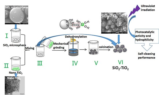
:In order to improve the dispersion of nano-TiO2 particles and enhance its self-cleaning properties, including photocatalytic degradation of pollutants and surface hydrophilicity, we prepared nano-TiO2-coated SiO2 microsphere composite self-cleaning materials (SiO2–TiO2) by co-grinding SiO2 microspheres and TiO2 soliquid and calcining the ground product. The structure, morphology, and self-cleaning properties of the SiO2–TiO2 were characterized. The characterization results showed that the degradation efficiency of methyl orange by SiO2–TiO2 was 97%, which was significantly higher than that obtained by pure nano-TiO2. The minimum water contact angle of SiO2–TiO2 was 8°, indicating strong hydrophilicity and the good self-cleaning effect. The as-prepared SiO2–TiO2 was characterized by the nano-TiO2 particles uniformly coated on the SiO2 microspheres and distributed in the gap among the microspheres. The nano-TiO2 particles were in an anatase phase with the particle size of 15–20 nm. The nano-TiO2 particles were combined with SiO2 microspheres via the dehydroxylation of hydroxyl groups on their surfaces.
1. Introduction
Nano-titanium dioxide (TiO2) is a typical semiconductor material with excellent properties. Moreover, it is stable, cheap, and non-toxic [1,2]. Therefore, it has been widely applied in the environmental protection [3], energy [4], and other fields [5,6]. In addition to the photocatalytic activity of TiO2 under ultraviolet (UV) irradiation, the self-cleaning effect due to photoinduced hydrophilic properties of TiO2 has always been one of the hotspots [7,8]. Its self-cleaning mechanism is generally ascribed to two effects [9,10]. Firstly, under the irradiation of ultraviolet light or ultraviolet in sunlight, the active components induced by the photocatalytic action of TiO2 on the TiO2 self-cleaning film can react with the pollutants adhering to the surface, thus achieving the decomposition of pollutants. Secondly, due to the super-hydrophilicity of the self-cleaning film, the decomposed products can be washed away by rain, so as to maintain the clean material surface [11]. In China and other developing countries, the contents of dust and oily dirt are high in the urban atmosphere and dust and oily dirt tend to adhere to building walls and glass surface to make the surface dirty. Nano-TiO2 self-cleaning materials may be used to coat such surfaces [12,13].
However, some factors restrict the application scope of nano-TiO2 self-cleaning materials. For example, the agglomeration phenomenon and poor dispersivity of TiO2 particles in the application system significantly reduces its self-cleaning effect [14,15]. Coating TiO2 particles on the matrix surface can significantly improve the dispersibility of TiO2 particles and enhance the photocatalytic efficiency and self-cleaning performance under the synergistic effect of the matrix [16,17]. In this way, the aforementioned problems may be solved. Many silicon materials are used as substrates to prepare nano-TiO2 coated composite catalysts, such as quartz tube [18], glass fibers [19], and nano-silica [20]. These catalysts all exhibit the good photocatalytic activity with different functional characteristics. Meanwhile, the micro-nano-morphology of the carrier-based nanoparticles, which are constructed from the surface of the composite self-cleaning material, can also increase the roughness of the self-cleaning film and further improve the super-hydrophilicor super-hydrophobic properties [21,22] Prabhu [23] prepared the reduced graphene oxide (rGO)/TiO2 composite self-cleaning material according to the solvothermal method and improved the visible light absorption efficiency of the composite self-cleaning materials, which exhibited the good photocatalytic efficiency and super-hydrophilic performance under light irradiation. Zhou [24] added the prepared SiO2–TiO2 composite colloidal particles into the fluorocarbon coating and realized more stable self-cleaning performance than that of adding single nano-TiO2 particles under ultraviolet light irradiation, thus suggesting its possible industrial application in outdoor environments. Zhang [25] and Ciprian [26] prepared SiO2–TiO2 composite films by the sol-gel impregnation and freeze-drying deposition method and realized the excellent self-cleaning performance and high transmittance to visible light. In general, the abovementioned preparation methods of nano-TiO2 composite self-cleaning material have some problems, such as the high cost, the complicated process and the difficulty in large-scale production and application. Therefore, it is necessary to select cheap matrix materials and simple composite process. Surolia [27] prepared the TiO2-coated fly ash photocatalyst via the sol-gel method with the cheap fly ash as substrate, exhibiting well photocatalysis degradation performance. Therefore, it is an effective way to improve the efficiency of resource utilization by using natural mineral or industrial by-product as substrate to prepare nano-TiO2-coated photocatalytic material.
In this study, with SiO2 microspheres as the matrix, nano-TiO2-coated SiO2 microsphere composite self-cleaning materials (SiO2–TiO2) were prepared by the wet grinding of SiO2 microspheres and nano-TiO2 soliquid and the subsequent calcination of the ground product. Then, we determined the photocatalytic activity and photoinduced hydrophilicity of SiO2–TiO2, analyzed the structure and morphology, and discussed the mechanism of the interaction between TiO2 and SiO2 particles. The SiO2 microspheres used in this study were recovered from the by-product, silica fume, which was produced during the industrial production of fused zirconia. The SiO2 microspheres mainly exist in the amorphous phase and have regular morphology, high surface activity, and low cost [28,29]. However, during the past years, silica fume was usually applied in cement, concrete and refractory products as an additive and its use efficiency was low [30,31]. To the best of our knowledge, the preparation of functional materials including composite photocatalytic materials with SiO2 microsphere as a matrix was seldom reported. In the study, the spherical shape of the SiO2 microspheres can increase the fluidity of SiO2–TiO2 and promote the film formation process and the micrometer size of the SiO2 can improve the recyclability of nano-TiO2. It is expected that the SiO2 microspheres can exert a synergistic effect on the performance of SiO2–TiO2 and reduce the cost of composite self-cleaning materials [25]. Meanwhile, the mechanical-chemical grinding method used in this study is a simple and non-pollution particle compound method. We prepared the SiO2–TiO2 composite materials with the good photocatalysis activity and self-cleaning effect via a simple composite process with cheap matrix materials. The preparation process exhibits significant economic and environmental values.
2. Methods
2.1. Raw Materials and Reagents
The SiO2 microspheres used in this study were recovered from the by-product, silica fume, which was produced during the industrial production of fused zirconia and was provided by a zirconia production enterprise in Jiaozuo (Jiaozuo, China). The main chemical constituents (mass fraction, %) of SiO2 microspheres were 93.78% SiO2 and 4.96% ZrO2. SiO2 is mainly composed of amorphous phase, exhibiting the microsphere morphology with the particle size of 1–3 μm. The SiO2 particles are aggregated to form the aggregates with the larger particle size. After depolymerizing the aggregates, the SiO2 microspheres exist in a dispersed state.
Tetrabutyl titanate (C16H36O4Ti) from Beijing Chemical Industry Group Co., Ltd. (Beijing, China) was used as the titanium source. Acetylacetone (C5H8O2) supplied by Xi Long Chemical Co., Ltd. (Guangzhou, China) was used as a hydrolysis control agent. Methyl orange (C14H14N3SO3Na) from Beijing Chemical Industry Group Co., Ltd. (Beijing, China) was used as a target pollution for photocatalytic degradation. Ethanol and deionized water are also used as solvents throughout the preparation process.
2.2. Preparation Method
2.2.1. Depolymerization of SiO2 Microspheres
Considering the agglomeration effect of particles in the raw SiO2 microspheres, SiO2 microspheres need to be depolymerized and dispersed before compositing with nano-TiO2. The depolymerization method was described as follows: The SiO2 microsphere materials were added into the ethanol solution to form a suspension. After adding ceramic grinding balls (the ratio of ball to material, 3:1), the suspension was then ground in the mixing mill (CSDM-S3, Beijing Paleozoic Powder Technology Co., Ltd., Beijing, China) for 60 min. Finally, the dispersed SiO2 microspheres were obtained after ball-material separation, filtration, and desiccation.
2.2.2. Preparation of Nano-TiO2 Soliquid
Firstly, 8.5 mL of tetrabutyl titanate was dissolved into 10 mL of ethanol solution. The mixed solution was stirred evenly and marked as Solution A. Then, 1.3 mL of acetylacetone was dissolved into 10 mL of ethanol solution, and the obtained solution was marked as Solution B. Then, Solution B was slowly added into Solution A and 19.35 mL of the mixture of ethanol and water (water 0.85 mL) was also added into Solution A. Afterwards, the mixture was stirred vigorously at room temperature for 12 h and the stirred mixture was aged for 48 h to obtain the nano-TiO2 soliquid. The viscosity of the nano-TiO2 soliquid obtained after 48-h aging was measured to be 2 × 10⁻³ Pa·s by a digital display viscometer (NDJ-8S, Shanghai Precision Instrument and Meter Co., Ltd., Shanghai, China). For comparison, partial nano-TiO2 soliquid was dried and calcined to prepare TiO2 nanoparticles. According to the X-ray diffraction (XRD) data and the Scherrer Equation, the grain size of nano-TiO2 was calculated to be 15–20 nm.
2.2.3. Preparation of SiO2–TiO2
Firstly, the dispersed SiO2 microspheres were added into the ethanol solution, which was stirred to form a suspension. Secondly, the suspension was added into the aged nano-TiO2 soliquid to form the SiO2/TiO2 mixture. Thirdly, the SiO2/TiO2 mixture were stirred by a CSDM-S3 mixing mill (Beijing Gosdel Powder&Technology Co., Ltd., Beijing, China) for 90 min after the addition of a certain amount of grinding balls to obtain the SiO2/TiO2 soliquid composites. Then, the SiO2/TiO2 soliquid composites were put in a SRJX-5-13 chamber electric furnace (Tianjin Taisite Instrument Co., LTD, Tianjin, China) and calcined at 500 °C for 2 h. Finally, the SiO2–TiO2 was prepared.
2.3. Characterization
2.3.1. Evaluation of Self-Cleaning Performance
Photocatalytic Activity
The photocatalytic degradation performance of SiO2–TiO2 was tested with the methyl orange as the target degradation pollutant. The system was irradiated by a mercury lamp (100 W, the main wavelength of 254 nm). Then, 40 mg of SiO2–TiO2 was added to 50 mL of prepared methyl orange dilution (concentration 10 mg/L). In order to reduce the measurement error caused by sample adsorption, the dark reaction was carried out for 0.5 h and then the concentration of methyl orange (C0) in the solution was measured. After turning on the light source, the concentration of methyl orange (C) in solution was measured every 20 min. The photocatalytic degradation performance of the samples was characterized and evaluated based on the change of C/C0.
The concentration of methyl orange was measured according to the following procedure. Firstly, the solution was centrifuged and the absorbance of the supernatant was measured with a Cary 5000 UV–VIS spectrophotometer (USA Varian, Palo Alto, CA, USA). The concentration of methyl orange in the solution was calculated according to the relationship between absorbance and concentration.
Hydrophilicity
The hydrophilicity of the SiO2–TiO2 particles was characterized based on the wetting degree of water on its surface. The wetting degree was reflected by the measured water contact angle on its surface. The SiO2–TiO2 composite powder was pressed into a sheet-like sample by a tableting machine and then the water contact angle was measured by a contact angle meter (JC2000D, Shanghai Zhongchen Digital Technic Apparatus Co. Ltd., Shanghai, China) three times. The measurement results were averaged.
2.3.2. Characterization of Structure and Morphology
We observed the morphology of SiO2–TiO2 by scanning electron microscope (SEM) (S-3500N, Hitachi, Ltd., Tokyo, Japan) and transmission electron microscope (TEM) (FEI Tecnai G2 F20, Portland, OR, USA). The surface functional groups were examined by an infrared spectroscope (Spectrum 100, PerkinElmer Instruments (Shanghai) Co., Ltd., Shanghai, China) with KBr as the medium, and the weights of each sample and KBr were, respectively, 1 and 200 mg. The phase analysis was carried out with an X-ray diffractometer (D/MAX2000, Rigaku Corporation, Tokyo, Japan).The specific surface areas of SiO2 and SiO2–TiO2 were tested by the QuadraSorb SI specific surface area analyzer (Quantachrome Instrument Company, Boynton Beach, FL, USA). In addition, the surface roughness of SiO2 microspheres and SiO2–TiO2 were evaluated using a Mutimode VIII atomic force microscope (Bruke, Fremont, CA, USA).
3. Results and Discussion
3.1. Properties of SiO2–TiO2
3.1.1. Photocatalytic Properties of SiO2–TiO2
Figure 1a represents the degradation behaviors of methyl orange dye during irradiation as a function of time (min) in the presence of SiO2–TiO2 with different TiO2 ratios (the mass ratio of TiO2 to SiO2–TiO2). As shown in Figure 1a, the SiO2 microspheres exhibit no degradation effect on methyl orange, whereas pure TiO2 has a certain degradation effect on methyl orange. All of the prepared SiO2–TiO2 materials exhibit the significantly higher photocatalytic degradation efficiency on methyl orange dye than that of pure nano-TiO2. Among these SiO2–TiO2 samples, with SiO2–TiO2-40 (TiO2 ratio is 40%) as the photocatalyst, after the solution was irradiated for 40 min, the C/Co was reduced to about 0.1 and the degradation efficiency reached 90%. After the 120 min irradiation, the degradation efficiency reached 97%. With the pure nano-TiO2 as the photocatalyst, the degradation efficiencies after 40 and 120 min respectively reached 50% and 90%. The abovementioned results indicated that the photocatalytic activity of nano-TiO2 had been greatly improved when TiO2 coated the surface of SiO2 microspheres. In addition, the TiO2 ratio had a significant effect on the degradation efficiency of SiO2–TiO2. With the increase in the TiO2 ratio from 20% to 40%, the photocatalytic degradation efficiency gradually increased and finally reached its maximum value. When the mass ratio of TiO2 increased to 50%, the degradation efficiency decreased. However, the degradation efficiency of SiO2–TiO2 with different TiO2 ratios was always higher than that of pure nano-TiO2. The phenomenon might be interpreted in two aspects: Firstly, the coating of nano-TiO2 on SiO2 microsphere surface could improve the dispersibility of nano-TiO2, thus resulting in an increase in the number of reactive groups under irradiation and increasing the quantum efficiency. Secondly, SiO2 had a high reflection efficiency on ultraviolet radiation, and the light reflected by SiO2 could be absorbed by TiO2, thus improving the absorption of ultraviolet light by SiO2–TiO2. The specific surface area analysis results showed that the surface area of SiO2 had been significantly incresed from its original value of 5.698 to 44.410 m2/g after TiO2 coating. This result also comfirmed that the SiO2 microspheres had been coated by nano TiO2 effectively.Figure 1b shows the influence of the ratio of grinding ball to materials (B-M) in the grinding process on the photocatalytic activity of SiO2–TiO2. The degradation efficiency of SiO2–TiO2 samples prepared with grinding balls was significantly higher than that of the SiO2–TiO2 prepared without grinding balls (B-M is 0). The degradation effect was the best when the B-M ratio was 5. After 120 min irradiation, the highest degradation efficiency was 95% (C/C0 = 0.05) at the B-M ratio of 5% and 65% at the B-M of 0. The above results showed that the grinding process had an important effect on the performance of SiO2–TiO2. Therefore, the proper B-M ratio should be selected. As shown in Figure 1b, the degradation effect of SiO2–TiO2 is stronger than that of pure nano-TiO2. The result is consistent with the results shown in Figure 1a.
The UV–VIS absorption spectra of bare SiO2 microspheres, nano-TiO2, and SiO2–TiO2-50 were obtained for comparison (Figure 2). The light absorption of SiO2 in a wavelength range between 300 and 400 nm was insignificant, whereas TiO2 absorbed light with the wavelength below 400 nm. The SiO2–TiO2 exhibited the higher light absorption in a wavelength range from 200 to 400 nm than that of pure nano-TiO2, which was completely different from bare SiO2 microspheres. The results indicated that the SiO2–TiO2 had the higher UV absorption due to the high reflection efficiency on ultraviolet radiation by SiO2 microspheres, confirming that SiO2 microspheres were coated by nano-TiO2 particles with similar light absorption properties to TiO2. Meanwhile, this results contribute to the good photocatalytic activity of SiO2–TiO2.
3.1.2. Hydrophilic Properties of SiO2–TiO2
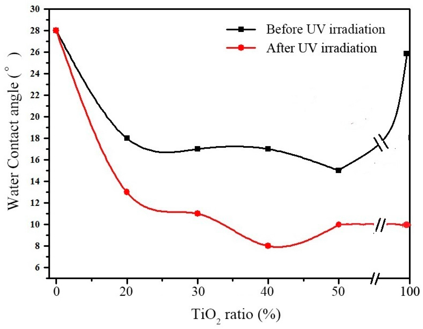
Figure 3 shows the change of water contact angle of SiO2–TiO2 particles with different TiO2 ratios after irradiation by ultraviolet light for 2 h. For the SiO2 microsphere materials, the contact angle was maintained to be 28° after UV irradiation, indicating that the UV light had no effect on its hydrophilicity. The water contact angle of pure TiO2 is 26° before UV irradiation, which is higher than that of SiO2–TiO2, indicating that the coating of TiO2 on SiO2 surface can improve the hydrophilicity of TiO2. The improvement effect may be interpreted as follows. The dispersion of nano-TiO2 was improved and then more active hydroxyl groups on TiO2 surface were exposed. Meanwhile, the water contact angle of pure TiO2 decreased from 26° to 10° after UV irradiation, indicating the photoinduced hydrophilicity of TiO2. The water contact angle of SiO2–TiO2 was 15–18° and decreased to 8–13° after UV irradiation, showing the strong hydrophilicity. The SiO2–TiO2-40 (TiO2 ratio is 40) showed the strongest hydrophilicity and its water contact angles were 17° and 8° before and after UV irradiation respectively. The strong photo-induced hydrophilicity and photocatalytic activity of SiO2–TiO2 indicate its good self-cleaning performance.
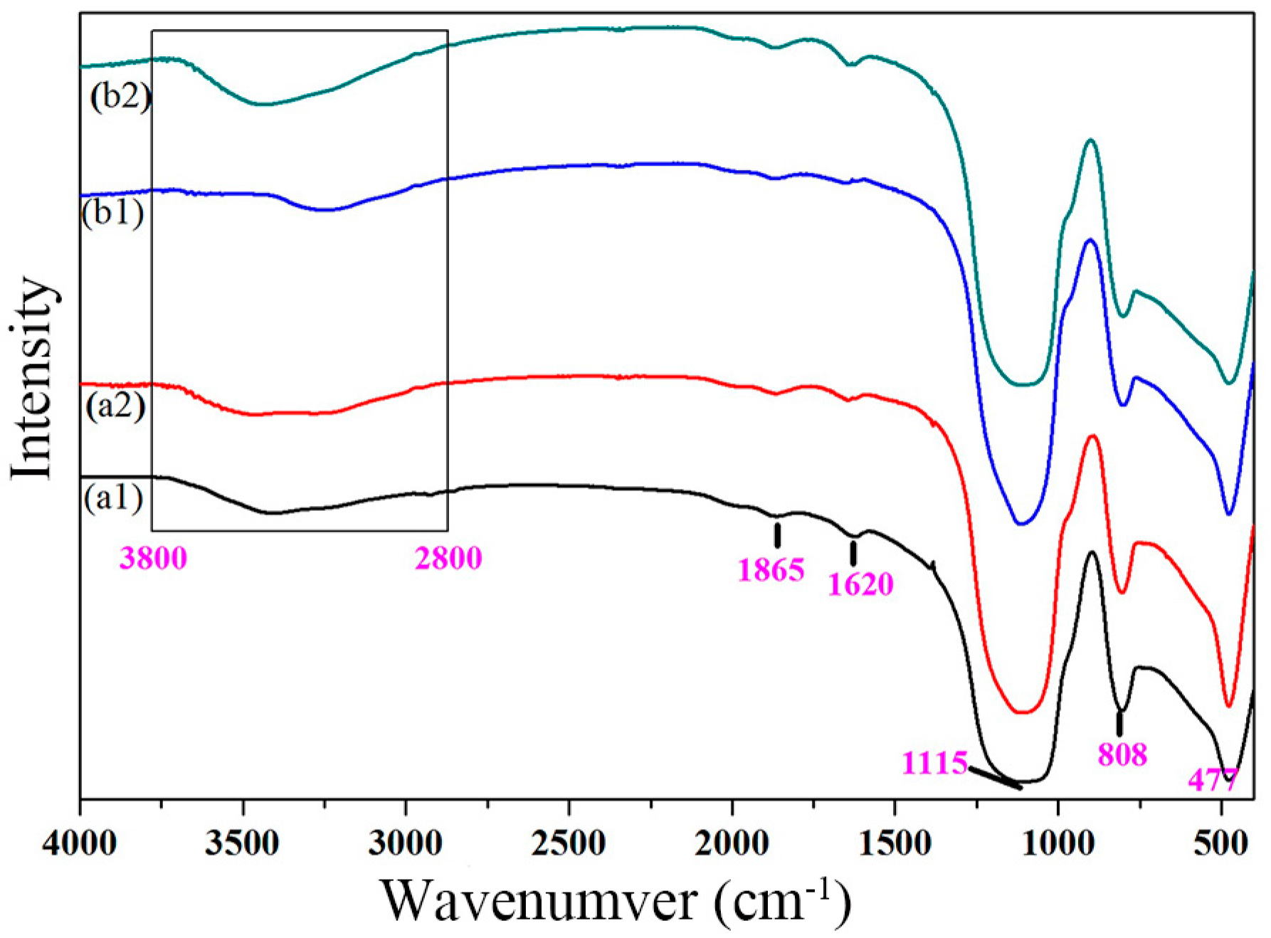
To investigate the mechanism of the photoinduced hydrophilicity of SiO2–TiO2, the infrared spectral analysis was carried out. Figure 4 shows the Fourier transform infrared spectroscopy (FT-IR) spectra of SiO2–TiO2-20 and SiO2–TiO2-30 before and after UV irradiation. The characteristic absorption peaks in the range of 2800–3800 cm−1 and 1620 cm−1 in all the samples were ascribed to the vibration of the hydroxyl groups on the SiO2–TiO2 surface. When the TiO2 ratio was 30%, after the UV irradiation (b2 in Figure 4), the intensity of the absorption peak in the range of 2800–3800 cm−1 in the FTIR spectrum of SiO2–TiO2 was higher than that in the spectrum b1 (before the UV irradiation) and the peak was shifted to the higher wavenumber. Meanwhile, the absorption peak at 1620 cm−1 in b2 was sharper than that in b1. The abovementioned results indicated that the number of hydroxyl groups on the surface of SiO2–TiO2 increased after UV irradiation and that the SiO2–TiO2 exhibited the reaction activity with water. We believed that the production of hydroxyl groups was induced by the photoinduced action of TiO2. The change was consistent with the remarkable enhancement of the surface hydrophilicity of SiO2–TiO2 after UV irradiation in Figure 3.
3.2. Structure and Morphology of SiO2–TiO2
3.2.1. XRD Analysis
Figure 5 shows the XRD patterns of SiO2–TiO2 with different TiO2 ratios. In addition to the diffraction peak of amorphous SiO2 microspheres, the diffraction peaks of the anatase phase also appeared in the XRD patterns of all SiO2–TiO2 samples, and the intensity of diffraction peaks of the anatase phase increased with the increase in the TiO2 ratio. Especially, when the TiO2 ratio was 50%, the complete anatase diffraction peak (JCPDS 21-1272) appeared in the XRD pattern of SiO2–TiO2-50 (Figure 5c) [32]. The abovementioned results indicated that nano-TiO2 existed as an anatase phase. Among all the TiO2 crystal phases, the anatase exhibited the highest photocatalytic activity, which was consistent with the results of photocatalytic activity and photoinduced hydrophilicity of SiO2–TiO2.
3.2.2. Morphology and Element Analysis
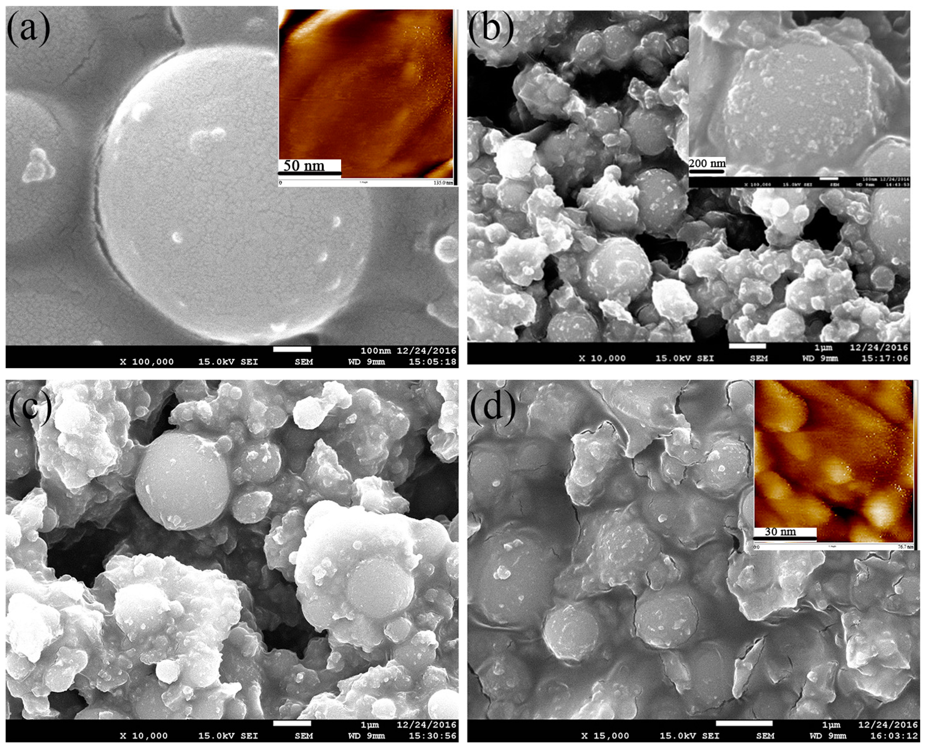
Figure 6 shows the SEM images of SiO2–TiO2 with different TiO2 ratios. In Figure 6a, the exposed surfaces of SiO2 microspheres are smooth without covering. However, the micron-submicron hierarchical structure morphology can be observed in Figure 6b–d. The surface of the SiO2 microspheres became rough and was covered with a certain amount of irregular particles. Meanwhile, with the increase in the TiO2 ratio, the roughness and coverage area of the SiO2 microsphere surface increased accordingly. According to the preparation process, it was presumed that the coating on the surface of the microspheres should be nano-TiO2 particles. The surface roughness of SiO2 microspheres and SiO2–TiO2-50 were evaluated using an atomic force microscope, and the corresponding atomic force microscope (AFM) images were shown in Figure 6a,d (see the built-in images). The tested surface roughness of SiO2 microspheres and SiO2–TiO2 were 1.63 and 18.4 nm, respectively. These results show that the surface roughness of SiO2 increased significantly after it was coated by nano-TiO2, indicating that the surface structure of SiO2 has changed. Additionally, in the magnification image of SiO2–TiO2 shown in Figure 6b, the nano-TiO2 particles not only uniformly coated the surface of the SiO2 microspheres, but also exist in the gap among SiO2 microspheres. In this way, several microspheres were connected together as a whole.
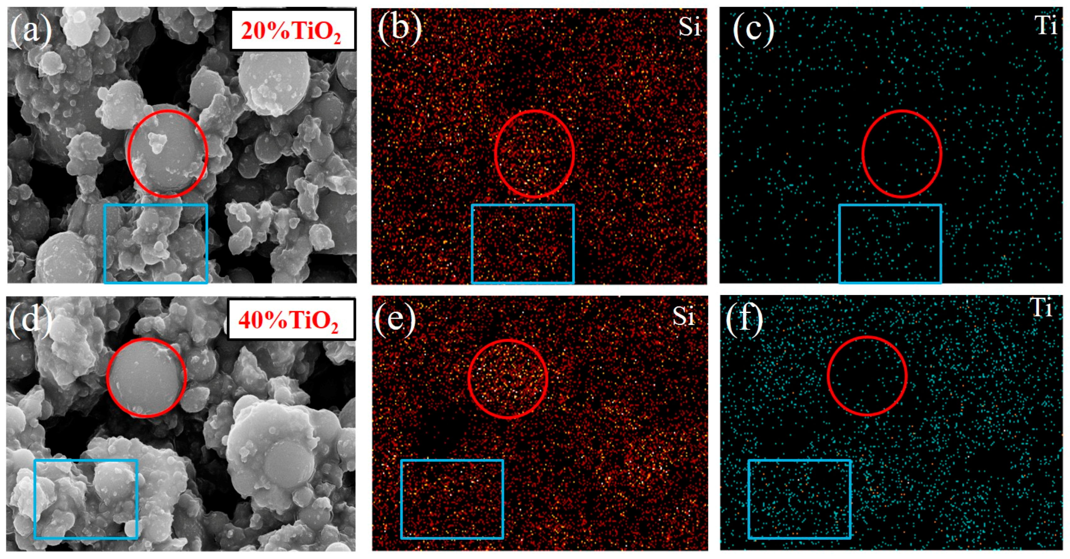
To confirm the composition of the coating on the surface of SiO2 microsphere, a surface scanning analysis of the main elements in the selected part of the SiO2–TiO2 SEM was carried out (Figure 7). The Ti element was almost distributed throughout the scan area, like the distribution of Si element. The distribution density of Ti element is proportional to the TiO2 ratio. This confirmed that the nano-TiO2 particles had coated the surface and were distributed in the gap among SiO2 microsphere. The results were consistent with SEM results (Figure 6).
Figure 8 shows the TEM and high resolution transmission electron microscopy (HRTEM) images of the SiO2–TiO2 samples (TiO2 ratio is 40%). Circular SiO2 microspheres and irregular nano-TiO2 particles surrounding the SiO2 microspheres are observed in Figure 8a, confirming that the nano-TiO2 particles has coated the surface of SiO2 microspheres. In the HRTEM (Figure 8c), the interplanar spacing of the three major facets were measured to be d = 0.352 nm [33], which was consistent with the (101) crystal face of anatase (JCPDS 21-1272). The above results indicated that the nano-TiO2 coating on the surface of SiO2 microspheres was anatase and that the mainly exposed crystal face was (101).
3.3. Mechanism of the Interaction between SiO2 and TiO2 Particles
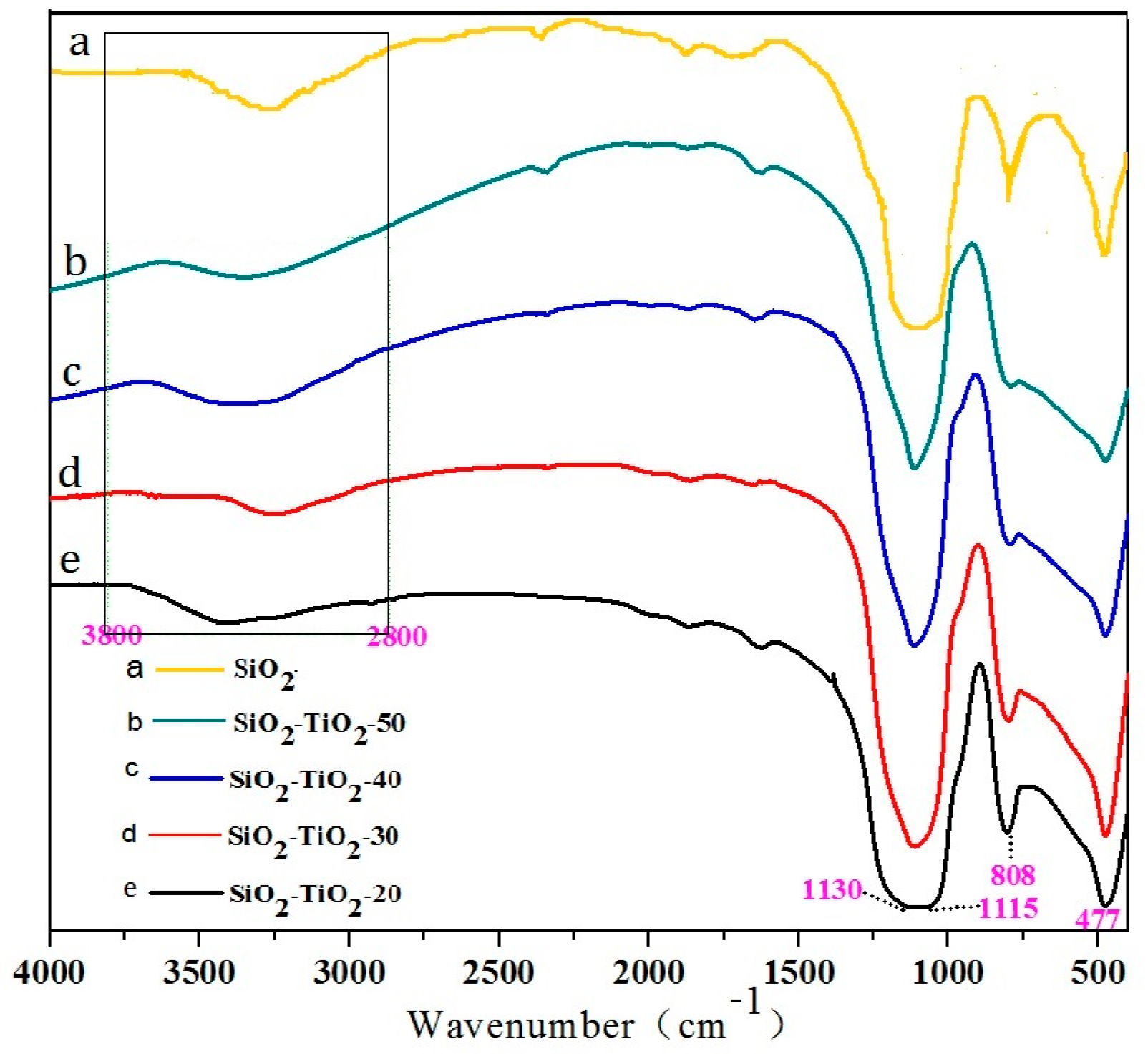
Figure 9 shows the FT-IR spectra of SiO2 and SiO2–TiO2 with different TiO2 ratios. The absorption bands at 1115, 808, and 477 cm−1 are typical absorption bands of Si–O bonds, indicating that the main component of the composite is SiO2 [34].With the increase in the TiO2 ratio, the intensity of absorption bands corresponding to SiO2 decreased, indicating that the nano-TiO2 coated the SiO2 surface. In addition, the absorption bands (3200–3550 cm−1) derived from Si–OH and Ti–OH showed the significant displacement and broadening phenomena when the SiO2 was coated by the nano-TiO2, indicating that the chemical environment had been changed and the association degree of hydroxyl groups on particles surface had increased. It was obviously caused by the formation of hydrogen bonds between Si–OH and Ti–OH or the further dehydroxylation reaction. It should be inferred that the chemical combination between SiO2 microspheres and nano-TiO2 particles was formed through the interaction of hydroxyl groups on their surfaces.
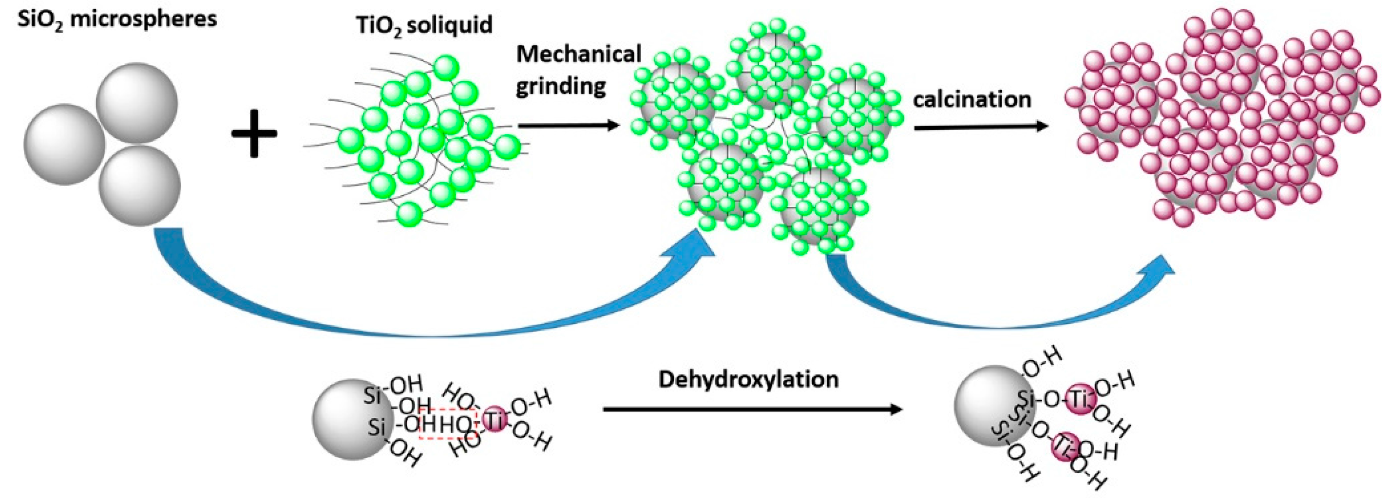
Figure 10 shows the schematic diagram of the bonding mechanism of SiO2–TiO2. Based on the above results, the bonding mechanism can be described as follows: firstly, the SiO2 microspheres were ground in the ethanol medium with grinding balls. The strong grinding force made SiO2 microspheres depolymerization and exposed more hydroxyl groups, thus displaying the higher reactivity. Secondly, the prepared nano-TiO2 soliquid was ground with the activated SiO2 violently, so that the collision probability between particles increased and lead to the contact and reactions between the hydroxyl groups on the SiO2 and TiO2 surfaces. Finally, water produced by the dehydroxylation of the particles was further removed by calcination. The SiO2 and TiO2 particles were bounded by –Si–O–Ti– bonds. The strength of the chemical bond was stronger than that of van der Waals forces and other physical forces, so the coating of nano-TiO2 on SiO2 surface was firm.
4. Conclusions
In the study, with the by-product SiO2 microspheres produced during the industry production of fused-zirconia as the substrates, SiO2–TiO2 particles were prepared by the wet-grinding of SiO2 microspheres and nano-TiO2 and calcination of the ground product. The degradation efficiency of SiO2–TiO2 on methyl orange reached 97%, which was significantly higher than that of pure nano-TiO2. The water contact angle of SiO2–TiO2 was 8°, indicating the strong photoinduced hydrophilicity and the good self-cleaning effect.
The SiO2–TiO2 particles were characterized by the nano-TiO2 uniformly coated on the SiO2 microspheres and distributed in the microsphere gap. The nano-TiO2 particles existed in an anatase phase with the particle size of 15–20 nm and are combined with SiO2 microspheres by the dehydration of hydroxyl groups on particle surfaces.
Author Contributions
Hao Ding, Tongrong Deng and Sijia Sun conceived and designed the experiments; Sijia Sun and Tongrong Deng performed the experiments; Sijia Sun, Tongrong Deng and Wanting Chen analyzed the data; Ying Chen contributed reagents/materials/analysis tools; Sijia Sun and Hao Ding wrote the paper. Authorship must be limited to those who have contributed substantially to the work reported.
Conflicts of Interest
The authors declare no conflict of interest.
References
- Liu, L.; Chen, X. Titanium dioxide nanomaterials: Self-structural modifications. Chem. Rev. 2014, 114, 9890–9918. [Google Scholar] [CrossRef] [PubMed]
- Kormann, C.; Bahnemann, D.W.; Hoffmann, M.R. Preparation and characterization of quantum-size titanium dioxide. J. Phys. Chem. C 1988, 92, 5196–5201. [Google Scholar] [CrossRef]
- Pu, S.; Zhu, R.; Ma, H.; Deng, D.; Pei, X.; Qi, F.; Chu, W. Facile in-situ design strategy to disperse TiO2 nanoparticles on graphene for the enhanced photocatalytic degradation of rhodamine 6G. Appl. Catal. B Environ. 2017, 218, 208–219. [Google Scholar] [CrossRef]
- Preethi, L.K.; Mathews, T.; Nand, M.; Jha, S.N.; Gopinath, C.S.; Dash, S. Band alignment and charge transfer pathway in three phase anatase-rutile-brookite TiO2, nanotubes: An efficient photocatalyst for water splitting. Appl. Catal. B Environ. 2017, 218, 9–19. [Google Scholar] [CrossRef]
- Ye, Z.; Tai, H.; Guo, R.; Yuan, Z.; Liu, C.; Su, Y.; Chen, Z.; Jiang, Y. Excellent ammonia sensing performance of gas sensor based on graphene/titanium dioxide hybrid with improved morphology. Appl. Surf. Sci. 2017, 419, 84–90. [Google Scholar] [CrossRef]
- Fu, H.; Yang, X.; An, X.; Fan, W.; Jiang, X.; Yu, A. Experimental and theoretical studies of V2O5@TiO2 core-shell hybrid composites with high gas sensing performance towards ammonia. Sens. Actuators B Chem. 2017, 252, 103–115. [Google Scholar] [CrossRef]
- Jalvo, B.; Faraldos, M.; Bahamonde, A.; Rosal, R. Antimicrobial and antibiofilm efficacy of self-cleaning surfaces functionalized by TiO2 photocatalytic nanoparticles against staphylococcus aureus and pseudomonas putida. J. Hazard. Mater. 2017, 340, 160–170. [Google Scholar] [CrossRef] [PubMed]
- Tan, B.Y.L.; Tai, M.H.; Juay, J.; Liu, Z.; Sun, D. A study on the performance of self-cleaning oil–water separation membrane formed by various TiO2, nanostructures. Sep. Purif. Technol. 2015, 156, 942–951. [Google Scholar] [CrossRef]
- Ganesh, V.A.; Raut, H.K.; Nair, A.S.; Ramakrishna, S. A review on self-cleaning coatings. J. Mater. Chem. A 2011, 21, 16304–16322. [Google Scholar] [CrossRef]
- Kim, S.M.; In, I.; Park, S.Y. Study of photo-induced hydrophilicity and self-cleaning property of glass surfaces immobilized with TiO2 nanoparticles using catechol chemistry. Surf. Coat. Technol. 2016, 294, 75–82. [Google Scholar] [CrossRef]
- Petica, A.; Gaidau, C.; Ignat, M.; Sendrea, C.; Anicai, L. Doped TiO2 nanophotocatalysts for leather surface finishing with self-cleaning properties. J. Coat. Technol. Res. 2015, 12, 1153–1163. [Google Scholar] [CrossRef]
- Diamanti, M.V.; Paolini, R.; Rossini, M.; Aslan, A.B.; Zinzi, M.; Poli, T.; Pedeferri, M.P. Long term self-cleaning and photocatalytic performance of anatase added mortars exposed to the urban environment. Constr. Build. Mater. 2015, 96, 270–278. [Google Scholar] [CrossRef]
- Rao, X.; Liu, Y.; Fu, Y.; Liu, Y.; Yu, H. Formation and properties of polyelectrolytes/TiO2 composite coating on wood surfaces through layer-by-layer assembly method. Holzforschung 2016, 70, 361–367. [Google Scholar] [CrossRef]
- Lei, M.; Li, F.S.; Tanemura, S.; Fisher, C.A.J.; Li, L.Z.; Liang, Q.; Xu, G. Cost-effective nanoporous SiO2–TiO2, coatings on glass substrates with antireflective and self-cleaning properties. Appl. Energy 2013, 112, 1198–1205. [Google Scholar]
- Diamanti, M.V.; Gadelrab, K.R.; Pedeferri, M.P.; Stefancich, M.; Pehkonen, S.O.; Chiesa, M. Nanoscale investigation of photoinduced hydrophilicity variations in anatase and rutile nanopowders. Langmuir 2013, 29, 14512–14518. [Google Scholar] [CrossRef] [PubMed]
- Calia, A.; Lettieri, M.; Masieri, M. Durability assessment of nanostructured TiO2, coatings applied on limestones to enhance building surface with self-cleaning ability. Build. Environ. 2016, 110, 1–10. [Google Scholar] [CrossRef]
- Jo, W.K.; Tayade, R.J. Facile photocatalytic reactor development using nano-TiO2 immobilized mosquito net and energy efficient UVLED for industrial dyes effluent treatment. J. Environ. Chem. Eng. 2016, 4, 319–327. [Google Scholar] [CrossRef]
- Natarajan, K.; Natarajan, T.S.; Tayade, R.J. Photocatalytic reactor based on UV-LED/TiO2 coated quartz tube for degradation of dyes. Chem. Eng. J. 2011, 178, 40–49. [Google Scholar] [CrossRef]
- Yang, S.B.; Chun, H.H.; Tayade, R.J.; Jo, W.K. Iron-functionalized titanium dioxide on flexible glass fibers for photocatalysis of benzene, toluene, ethylbenzene, and o-xylene (BTEX) under visible- or ultraviolet-light irradiation. J. Air Waste Manag. 2015, 65, 365–373. [Google Scholar] [CrossRef] [PubMed]
- Smitha, V.S.; Manjumol, K.A.; Baiju, K.V.; Ghosh, S.; Perumal, P.; Warrier, K.G.K. Sol–gel route to synthesize titania-silica nano precursors for photoactive particulates and coatings. J. Sol-Gel Sci. Technol. 2010, 54, 203–211. [Google Scholar] [CrossRef]
- Shi, G.; Chen, J.; Wang, L.; Wang, D.; Yang, J.; Li, Y.; Zhang, L.; Ni, C.; Chi, L. Titanium oxide/silicon moth-eye structures with antireflection, p–n heterojunctions and superhydrophilicity. Langmuir 2016, 32, 27666724. [Google Scholar] [CrossRef] [PubMed]
- Pakdel, E.; Daoud, W.A. Self-cleaning cotton functionalized with TiO2/SiO2 focus on the role of silica. J. Colloid Interface Sci. 2013, 401, 1–7. [Google Scholar] [CrossRef] [PubMed]
- Prabhu, S.; Cindrella, L.; Kwon, O.J.; Mohanraju, K. Superhydrophilic and self-cleaning RGO–TiO2, composite coatings for indoor and outdoor photovoltaic applications. Sol. Energy Mater. Sol. Cells 2017, 169, 304–312. [Google Scholar] [CrossRef]
- Zhou, J.; Tan, Z.; Liu, Z.; Jing, M.; Liu, W.; Fu, W. Preparation of transparent fluorocarbon/TiO2-SiO2, composite coating with improved self-cleaning performance and anti-aging property. Appl. Surf. Sci. 2017, 396, 161–178. [Google Scholar] [CrossRef]
- Zhang, H.; Fan, D.; Yu, T.; Wang, C. Characterization of anti-reflective and self-cleaning SiO2–TiO2, composite film. J. Sol-Gel Sci. Technol. 2013, 66, 274–279. [Google Scholar] [CrossRef]
- Ciprian, M.; Alexandru, E.; Anca, D. SiO2/TiO2 multi-layered thin films with self-cleaning and enhanced optical properties. Bull. Mater. Sci. 2017, 40, 1–10. [Google Scholar] [CrossRef]
- Surolia, P.K.; Tayade, R.J.; Jasra, R.V. TiO2-coated cenospheres as catalysts for photocatalytic degradation of methylene blue, p-nitroaniline, n-decane, and n-tridecane under solar irradiation. Ind. Eng. Chem. Res. 2010, 49, 8908–8919. [Google Scholar] [CrossRef]
- Mavukkandy, M.O.; Bilad, M.R.; Kujawa, J.; Al-Gharabli, S.; Arafat, H.A. On the effect of fumed silica particles on the structure, properties and application of PVDF membranes. Sep. Purif. Technol. 2017, 187, 365–373. [Google Scholar] [CrossRef]
- Peng, Y.; Zhang, J.; Liu, J.; Ke, J.; Wang, F. Properties and microstructure of reactive powder concrete having a high content of phosphorous slag powder and silica fume. Constr. Build. Mater. 2015, 101, 482–487. [Google Scholar] [CrossRef]
- Pedro, D.; Brito, J.D.; Evangelista, L. Mechanical characterization of high performance concrete prepared with recycled aggregates and silica fume from precast industry. J. Clean. Prod. 2017, 164, 939–949. [Google Scholar] [CrossRef]
- Liu, J.; Wang, D. Influence of steel slag-silica fume composite mineral admixture on the properties of concrete. Powder Technol. 2017, 320, 230–238. [Google Scholar] [CrossRef]
- Wang, S.; Zheng, W.T.; Lian, J.S.; Jiang, Q. Photocatalytic property of Fe doped anatase and rutile TiO2 nanocrystal particles prepared by sol–gel technique. Appl. Surf. Sci. 2012, 263, 260–265. [Google Scholar] [CrossRef]
- Zhou, X.; Wu, J.; Zhang, J.; He, P.; Ren, J.; Zhang, J.; Lu, J.; Liang, P.; Xu, K.; Shui, F. The effect of surface heterojunction between (001) and (101) facets on photocatalytic performance of anatase TiO2. Mater. Lett. 2017, 205, 173–177. [Google Scholar] [CrossRef]
- Chen, Y.; Ding, H.; Sun, S. Preparation and characterization of ZnO nanoparticles supported on amorphous SiO2. Nanomaterials 2017, 7, 217. [Google Scholar] [CrossRef] [PubMed]
Figure 1.
Influences of (a) TiO2 ratio and (b) B-M ratio on the photocatalytic performance of SiO2–TiO2. (a) SiO2–TiO2-20, 30, 40, 50 represent the mass ratio of TiO2 to SiO2–TiO2 is 20%, 30%, 40% and 50%; and (b) B-M represents the mass ratio of grinding balls to the materials.
Figure 1.
Influences of (a) TiO2 ratio and (b) B-M ratio on the photocatalytic performance of SiO2–TiO2. (a) SiO2–TiO2-20, 30, 40, 50 represent the mass ratio of TiO2 to SiO2–TiO2 is 20%, 30%, 40% and 50%; and (b) B-M represents the mass ratio of grinding balls to the materials.
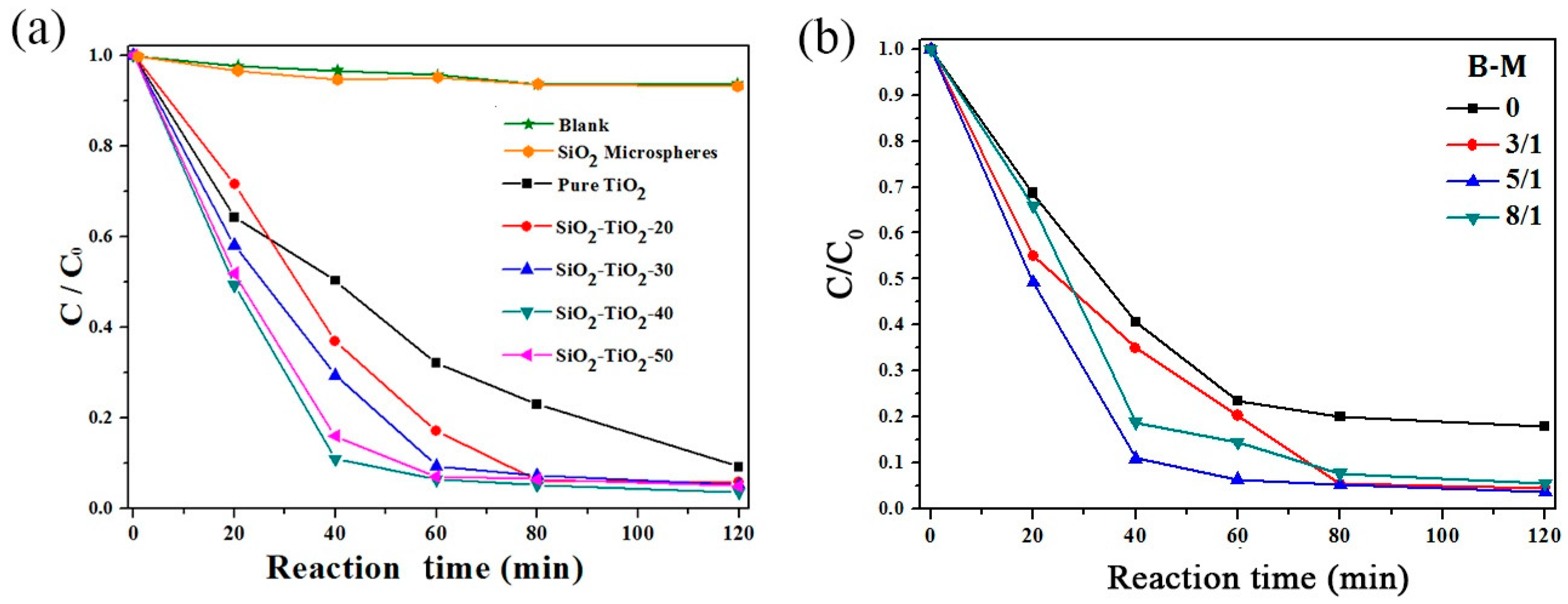
Figure 2.
UV–VIS absorption spectra of pure TiO2, SiO2 microsphere and SiO2–TiO2.
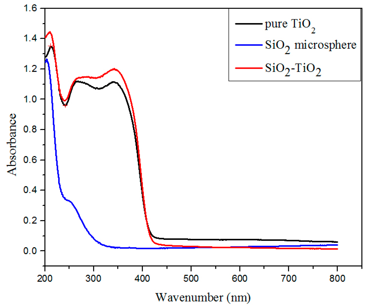
Figure 3.
Relationship between the water contact angle and the content of TiO2.

Figure 4.
Fourier transform infrared spectroscopy (FT-IR) spectrum of the SiO2–TiO2 with different TiO2 ratios. (a1) SiO2–TiO2-20, before UV irradiation; (a2) SiO2–TiO2-20, after UV irradiation; (b1) SiO2–TiO2-30, before UV irradiation; and (b2) SiO2–TiO2-30, after UV irradiation; The black rectangle region represents the absorption bands caused by the vibration of the hydroxyl radical

Figure 5.
XRD patterns of SiO2–TiO2 with different TiO2 ratios. (a) 30% TiO2; (b) 40% TiO2; and (c) 50% TiO2.
Figure 5.
XRD patterns of SiO2–TiO2 with different TiO2 ratios. (a) 30% TiO2; (b) 40% TiO2; and (c) 50% TiO2.
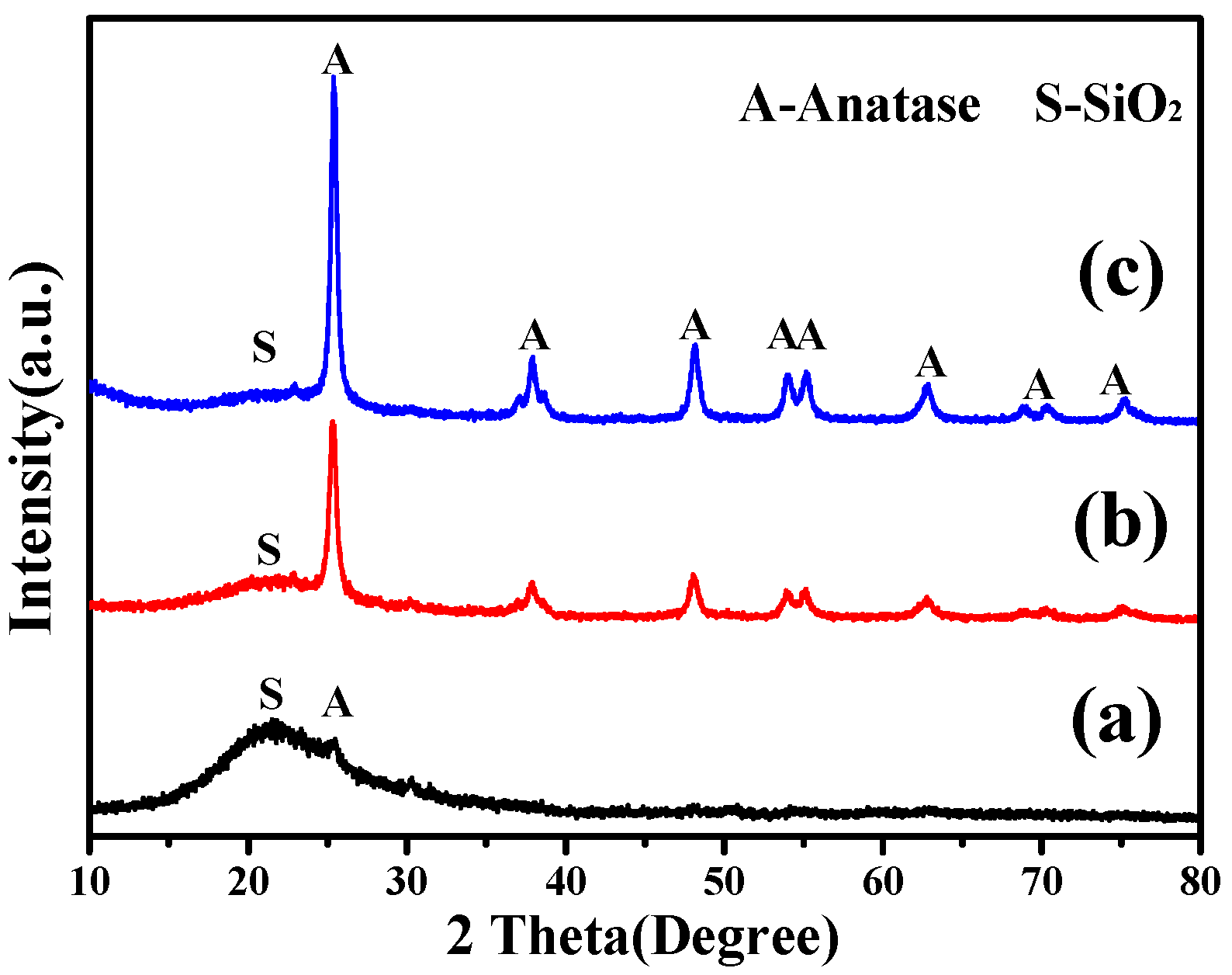
Figure 6.
Scanning electron microscope (SEM) and atomic force microscope (AFM) images of (a) SiO2 microsphere and (b–d) SiO2–TiO2 with different ratios. (b) 30% TiO2, and the inset image is a high magnification image; (c) 40% TiO2; and (d) 50% TiO2; the inset images in (a,d) are AFM images.
Figure 6.
Scanning electron microscope (SEM) and atomic force microscope (AFM) images of (a) SiO2 microsphere and (b–d) SiO2–TiO2 with different ratios. (b) 30% TiO2, and the inset image is a high magnification image; (c) 40% TiO2; and (d) 50% TiO2; the inset images in (a,d) are AFM images.

Figure 7.
Scanning results of surface elements of SiO2–TiO2 with (a–c) 20% TiO2 and (d–f) 40% TiO2.

Figure 8.
(a,b) Transmission electron microscope (TEM) and (c) high resolution transmission electron microscopy (HRTEM) images of SiO2–TiO2 at different scales.
Figure 8.
(a,b) Transmission electron microscope (TEM) and (c) high resolution transmission electron microscopy (HRTEM) images of SiO2–TiO2 at different scales.
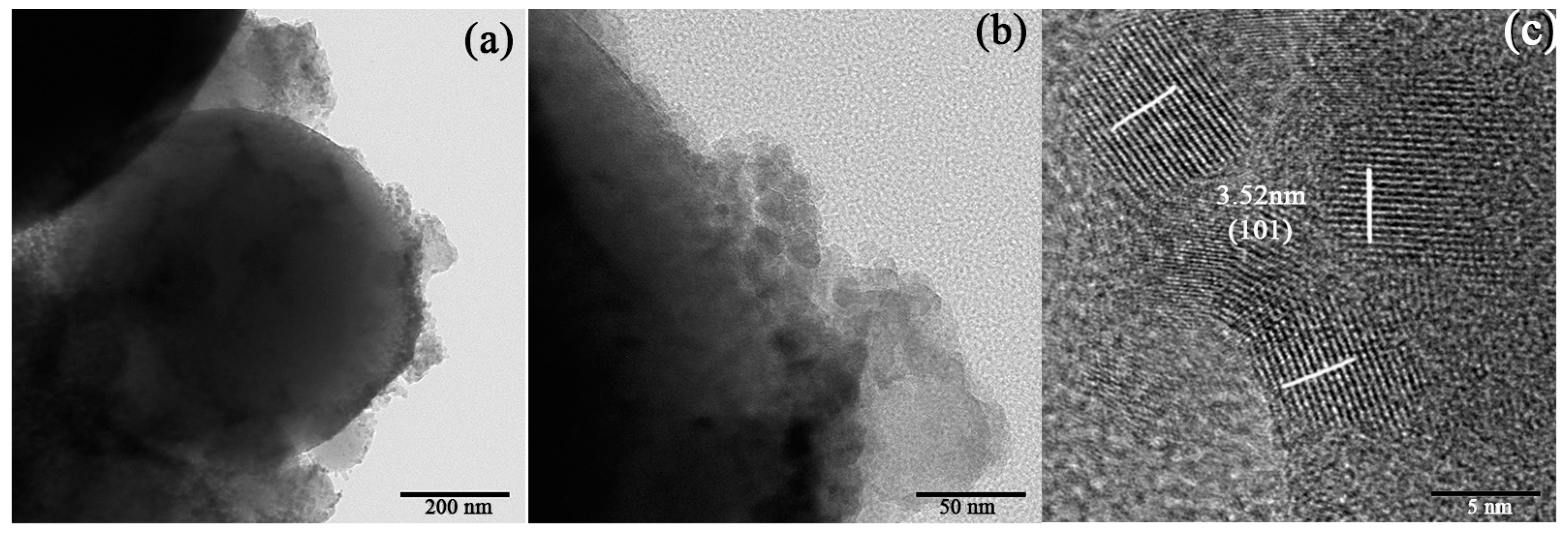
Figure 9.
FT-IR of SiO2–TiO2 with different TiO2 ratios. SiO2–TiO2-20, 30, 40, 50 represent the mass ratio of TiO2 to SiO2–TiO2 is 20%, 30%, 40% and 50%; The black rectangle region represents the absorption peak caused by the vibration of the hydroxyl radical.
Figure 9.
FT-IR of SiO2–TiO2 with different TiO2 ratios. SiO2–TiO2-20, 30, 40, 50 represent the mass ratio of TiO2 to SiO2–TiO2 is 20%, 30%, 40% and 50%; The black rectangle region represents the absorption peak caused by the vibration of the hydroxyl radical.

Figure 10.
Schematic diagram of the bonding mechanism of SiO2–TiO2.
© 2017 by the authors. Licensee MDPI, Basel, Switzerland. This article is an open access article distributed under the terms and conditions of the Creative Commons Attribution (CC BY) license (http://creativecommons.org/licenses/by/4.0/).
Share and Cite
MDPI and ACS Style
Sun, S.; Deng, T.; Ding, H.; Chen, Y.; Chen, W. Preparation of Nano-TiO2-Coated SiO2 Microsphere Composite Material and Evaluation of Its Self-Cleaning Property. Nanomaterials 2017, 7, 367. https://doi.org/10.3390/nano7110367
AMA Style
Sun S, Deng T, Ding H, Chen Y, Chen W. Preparation of Nano-TiO2-Coated SiO2 Microsphere Composite Material and Evaluation of Its Self-Cleaning Property. Nanomaterials. 2017; 7(11):367. https://doi.org/10.3390/nano7110367
Chicago/Turabian StyleSun, Sijia, Tongrong Deng, Hao Ding, Ying Chen, and Wanting Chen. 2017. "Preparation of Nano-TiO2-Coated SiO2 Microsphere Composite Material and Evaluation of Its Self-Cleaning Property" Nanomaterials 7, no. 11: 367. https://doi.org/10.3390/nano7110367
Note that from the first issue of 2016, this journal uses article numbers instead of page numbers. See further details here.