Article

Understanding the Solid–Ice Interface Mechanism on the Hydrophobic Nano-Pillar Structure Epoxy Surface for Reducing Ice Adhesion

1
College of Materials Science and Technology, Nanjing University of Aeronautics and Astronautics, Nanjing 210016, China
2
Department of Materials Chemistry, Qiuzhen School, Huzhou University, 759 East 2nd Road, Huzhou 313000, China
*
Authors to whom correspondence should be addressed.
Coatings 2020, 10(11), 1043; https://doi.org/10.3390/coatings10111043
Submission received: 18 September 2020 / Revised: 16 October 2020 / Accepted: 20 October 2020 / Published: 29 October 2020
(This article belongs to the Special Issue Low Ice Adhesion Coatings)

Abstract

:
Ice accumulation on wind turbine blades reduces power generation efficiency and increases wind turbines’ maintenance cost, even causing equipment damage and casualties. In this work, in order to achieve passive anti-icing, a series of nano-pillar array structures with different diameters of from 100 to 400 nm and heights of from 400 to 1500 nm were constructed on the substrate bisphenol-A epoxy resin, which is generally used in the manufacturing of wind turbine blades. The as-constructed functional surface showed excellent water repellence, with a contact angle of up to 154.3°. The water repellence on the nano-pillar array structures could induce ultra-low ice adhesion as low as 7.0 kPa, finding their place in the widely recognized scope of icephobic materials. The underlying solid–ice interface mechanism was well revealed in regard to two aspects: the interface non-wetting regime and the stress concentration behavior on the nano-pillar array structured surface. A detailed discussion on both the factors presented here will help surface structure design and function of icephobic materials, especially for epoxy-based composite materials.

1. Introduction

Ice accumulation on wind blades affects turbines’ efficiency and makes the corresponding maintenance more expensive and difficult [1,2]. Active de-icing methods to deal with such problems are currently mainstream, such as heating and mechanical vibration. The extra functional adjuncts are mainly attached to the wind turbines to reduce or avoid ice accumulation [3,4]. However, such methods require a separate power supply and make maintenance procedures difficult and costly. Hence, a passive anti-icing strategy based on the material’s own hydrophobic/icephobic characteristics was quickly developed and has gained increasing attention in recent years [5,6,7].
Since the secret of the lotus leaf was discovered [8], many researchers proposed superhydrophobic materials as the pivotal point in the search for a passive anti-icing regime [9], as the air layer between the droplet and substrate could block the heat transfer in freezing conditions and result in an icing delay effect [10,11,12,13,14]. Moreover, various anti-icing/icephobic surfaces were built by imitating natural structures such as the lotus and nepenthes [5,15] to change the interface state by introducing an air layer and a lubricating layer on micro- and nano-structure surfaces [16,17,18,19]. On this basis, researchers have successively fabricated various hierarchically structured superhydrophobic coatings with excellent anti-icing performance [14,20,21]. Furthermore, icephobic silicone rubber and its coatings were developed with ultra-low ice adhesion [7,22,23,24], with some even displaying Pa-levels [19]. Such progress indicates the great application value for icephobic materials. However, recent research on icephobic materials is primarily based on soft elastic materials, such as polydimethylsiloxane (PDMS) [22,23,25], hydrogels [19,26], polypropylene (PP) [27], and polystyrene (PS) [28], which are seldom used in the wind turbine manufacturing industry. Relevant studies on icephobic epoxy resin and its composite materials are, therefore, of utmost necessity.
It is widely recognized that materials’ surface adhesion behavior is influenced by four major forces: hydrogen bonding, van der Waals force, mechanical force, and electrostatic interaction [3,29]. Changes in one or more of these factors can cause significant changes to the functioning of the solid–ice interface state [30]. In recent research on the solid–ice interface mechanism for low ice adhesion, ice stripping mechanisms were studied based on the solid–ice interface’s mechanical force, especially on the relationship between ice adhesion behavior and micro-structure morphology [31,32]. Since the other three forces, namely, hydrogen bonding, van der Waals force, and electrostatic interaction, are related to the chemical properties of the material itself [22], they are not easy to alter to have a further impact on icephobicity. Generally speaking, water vapor condenses quickly in micro-structures at the dew point [33], causing the supercooled micro-droplets to permeate the voids of microstructures before ice formation. Moreover, newly formed ice crystals tend to grow into the structure voids, compressing the suspended water droplet’s air layer. Therefore, it is not easy to keep naturally formed solid–ice interfaces in the Cassie–Baxter state. When the microstructure is filled with ice, the so-called interlock effect makes the ice adhesion strength increase significantly [31,32,34]. In this case, even if there is ice detached from the surface, it is more likely that the fracture occurs inside the ice rather than at the ice–substrate interface [31].
Nonetheless, it is also reported that ice adhesion strength could be deficient at some nano-structured superhydrophobic surfaces due to the air layer being kept in the Cassie–Baxter state [35,36]. In other words, the air layer in the interface between ice and substrate serves as a crack initiator for the subsequent de-icing procedure. Still, current studies on how nano-structures influence ice adhesion are mainly based on disordered nano-morphology. The studies on ordered micro- and nano-structures have only begun in recent years [28]. In such a context, nano-scale morphology is random and can barely be reproduced by other processing methods. For instance, the geometrical characteristic (such as structure volume fraction) of nano-wires produced by the hydrothermal method are beyond count. The icephobic law on such surfaces is associated with fabrication parameters (time, temperature, and etching solution) rather than geometrical characteristics, which can be directly used as a reference under different conditions. A universal solid–ice interface mechanism regarding how nano-structures influence ice adhesion behavior will significantly strengthen the development of a passive anti-icing strategy [3,22,31].
In this work, we constructed a series of nano-pillar arrays on an epoxy surface; the diameter and the height of the nano-pillar were precisely controlled using the anodic aluminum oxide (AAO) templating method. This study investigates the internal relationships between nano-structure, non-wetting behavior, and ice adhesion behavior. This study aims to reveal the universal solid–ice interface mechanism on the nano-structured epoxy surface.

2. Materials and Methods

2.1. Materials

The AAO membranes (20 mm × 20 mm × 1 mm) used to fabricate the nano-pillars were purchased from Shenzhen Topmembranes Technology Co., Ltd., Shenzhen, China. Diglycidyl ether of bisphenol A-based epoxy resin (LT5078 A) and curing agent (LT5078 B) were procured from Wells Advanced Materials (Shanghai) Co., Ltd., Shanghai, China. Fluoroalkylsilane (FAS-17) was obtained from Tokyo Chemical Industry Co., Ltd., Tokyo, Japan. Analytical grade phosphoric acid, hydrochloric acid, copper chloride, and ethanol were purchased from Sinopharm Chemical Reagent Co., Ltd., Nanjing, China.

2.2. Sample Preparation Procedure

To explore the influence of the structure volume fraction and nano-pillar height on the wettability of epoxy resin, the experiment was conducted using 10 different sizes of AAO membranes with pore diameters ranging from 100 to 400 nm and a pore depth ranging from 400 to 1500 nm. The diaIn a particular fabricating technique, as illustrated in Figure 1, epoxy resin was configured at a mass ratio of 10:3 by adding 1 wt % FAS-17. The as-prepared liquid resin mixture system was stirred by a magnetic bar for 15 min to make the mixture uniform, and the rotation speed was set at 6000 rpm. The uniformly mixed epoxy resin system was degassed in an ultrasonic cleaner (Skymen, JP-010T, Shenzhen, China) for 15 min with an ultrasonic frequency of 100 kHz at 30 °C. After the degassing procedure was completed, 5 mL of epoxy resin was added to the AAO template and cured for 2 h at 60 °C in a vacuum maintained within 80 to 200 Pa. After the completion of curing procedure, the aluminum matrix in AAO membranes was removed by dissolving it in 3 wt % copper chloride and 50 wt % hydrochloric acid aqueous solutions [37]. The residual alumina was removed by dissolving it in an aqueous solution of 10 wt % phosphoric acid at 45 °C for 1 h [38], finally obtaining the epoxy resin film samples with nano-pillar arrays.

2.3. Surface Characterization

Surface morphologies of the AAO templates and the nano-structured epoxy surface were viewed with scanning electron microscopy (Hitachi S4800, Tokyo, Japan). The EDS data were collected by an EDS detector (Hitachi S4800, Tokyo, Japan). Prior to the imaging and EDS detection, the epoxy samples were covered by a 3 nm layer of gold by a sputter coater (Cressington 208HR, Watford, UK). FTIR spectra (Nicolet Nexus670, Madison, WI, USA) were recorded to determine the organic groups on the epoxy surface.

2.4. Non-Wettability Test

The contact angle of a 4 μL reference water droplet with the sample surface was measured using a contact angle analysis meter (Kruss DSA100, Hamburg, Germany). The mean value of the five measurements was also determined. The surface energy of different EP surfaces was determined by the contact angle data measured under two kinds of droplets, deionized water and ethanol, which are polar and weakly polar liquids, respectively. The calculation was automatically accomplished by a series of python codes, presented in Appendix A.

2.5. Ice Adhesion Test

The ice adhesion strength was measured by a home-made device, mentioned in a paper published before [29]. The sample was placed on a self-made pillar-shaped polypropylene container (φ = 10 mm, h = 30 mm) filled with deionized water, and then kept at −18 °C freezing in a refrigerator for more than 24 h. After the ice column was stuck to the sample surface, the samples sticking with the ice column were carefully transported to a −18 °C cooling plate and kept for another 30 min. Then, the peak detachment force of the ice pillar was recorded using a force transducer [39]. Each sample was subjected to 10 individual ice adhesion strength tests. The formula used for calculating ice adhesion strength τ was: τ = F/A. F and A represent the recorded peak detaching force and the contact area of the ice column with the sample, respectively.

3. Results and Discussion

3.1. Surface Morphologies

The SEM morphology of the nano-pillar arrays is shown in Figure 2. Figure 2a,b is the SEM images of the pore structure on the AAO template and the copied nano-pillar design on the epoxy resin, respectively. The diameters of the nano-pore and nano-pillar are 300 nm. The nano-structures are of honeycomb arrangement. The diameter and spacing distance of the as-prepared epoxy nano-pillar arrays are consistent with the AAO templates. SEM images of different pore sizes and depths of AAO templates as well as fabricated epoxy surfaces are illustrated in Figures S1–S3. Detailed geometry characteristics and standard deviation are recorded at Tables S1 and S2. The sub-image shown in Figure 2a confirms that the AAO membrane surface appears as orange at room temperature in daylight. This is because the regular nano-pore arrays of the membrane surface can cause directional light scattering and refraction when the light is coming in. Due to differences in optical properties between alumina and epoxy resin, cyan appears on the surface of the resin nano-pillar array, as illustrated in the inset of Figure 2b, which shows unique scattering and refracting effects of cyan light.
A slight size deviation between the AAO template and the copied epoxy nano-pillar array is observed and marked in the SEM images in Figure 2. As is illustrated, the epoxy nano-pillar diameter is 3.6% larger than the pore size in the AAO template. Such deviation is explained as the synergistic effect of the size non-uniformity in the AAO template and the volume expansion in the curing process.

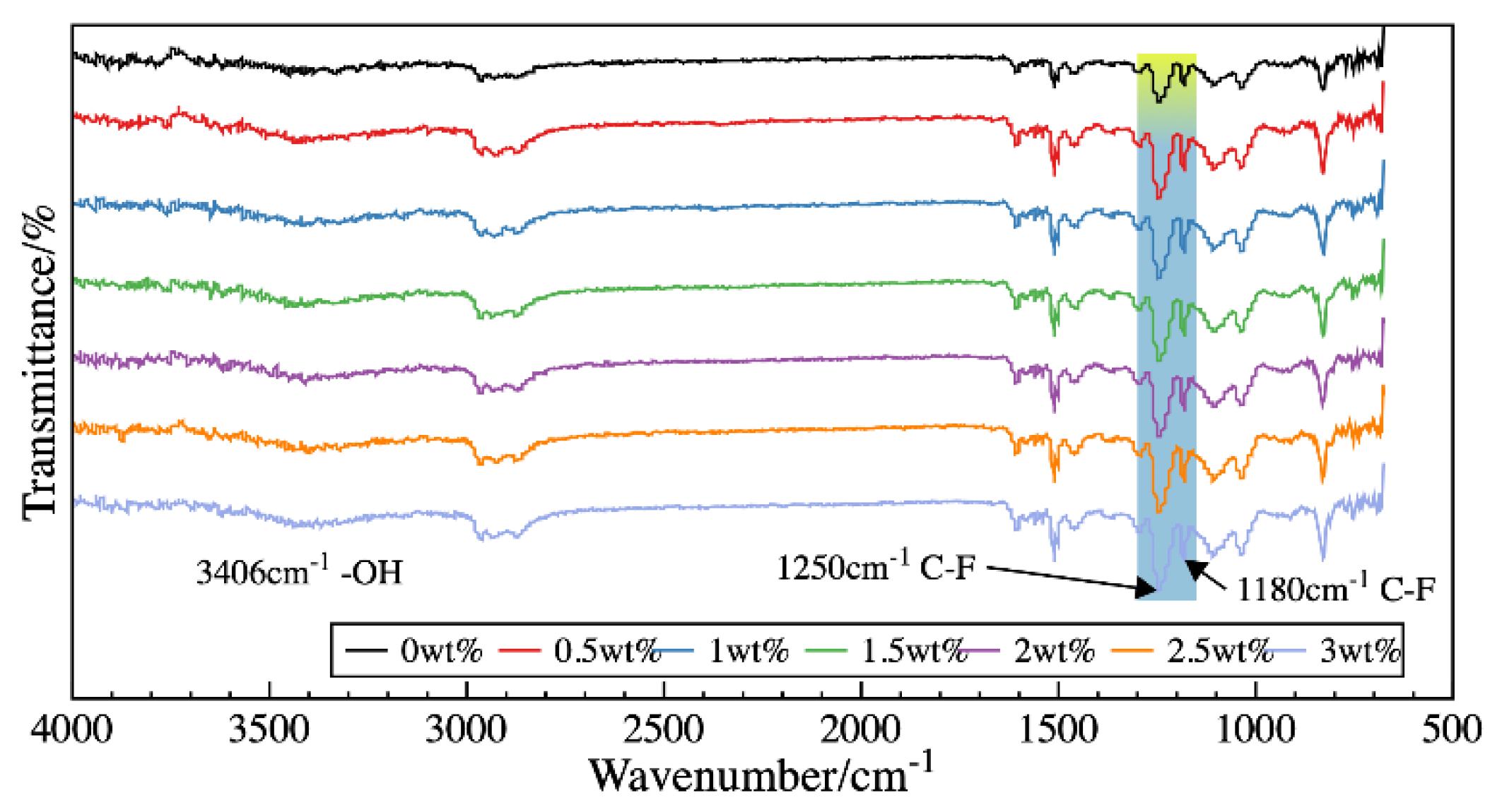
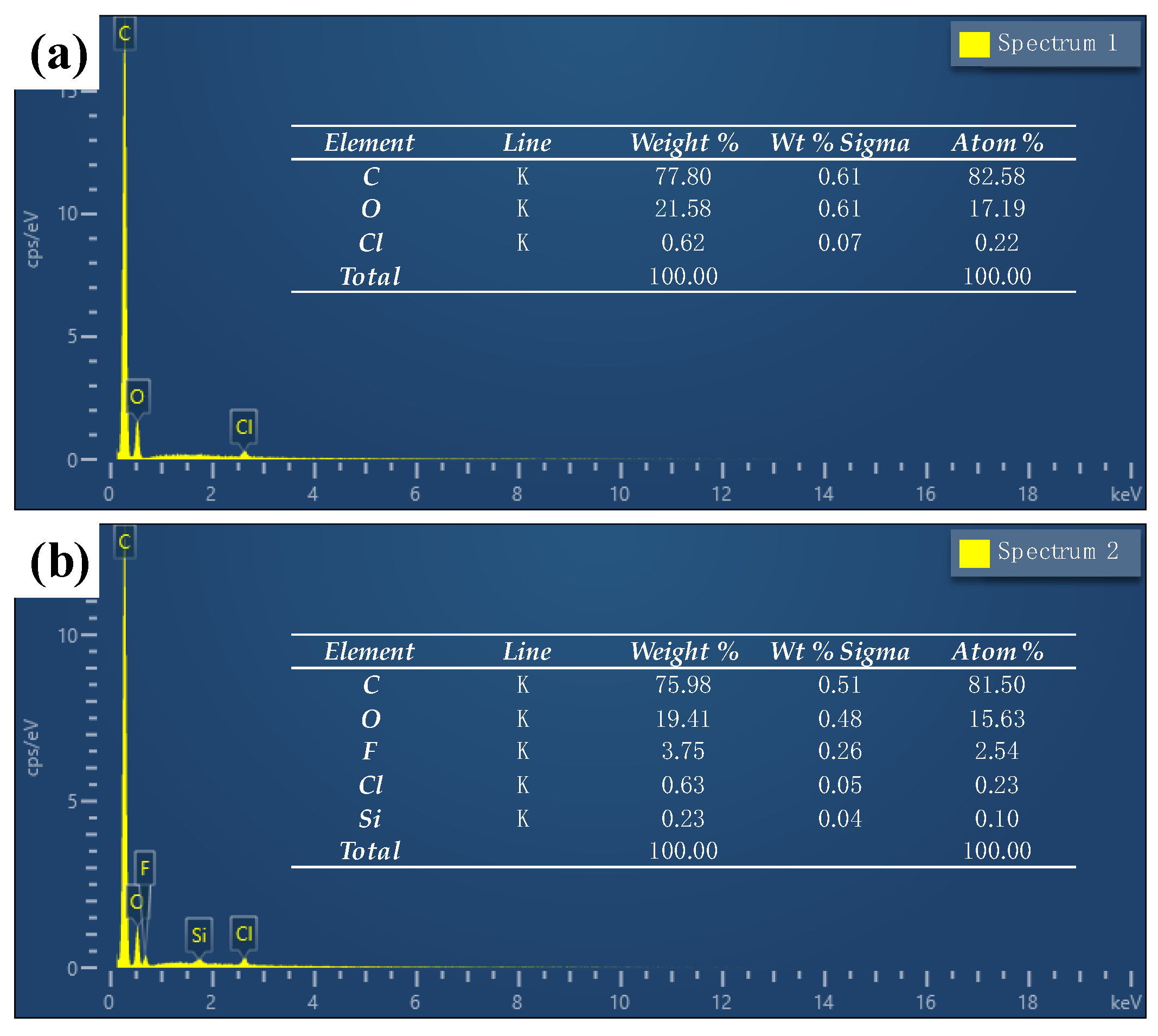
3.2. Characterization of Chemical Compositions

The FTIR spectra of epoxy resin component (A), curing agent (B), and cured epoxy resin are illustrated in Figure S4. The characteristic absorption peak of the amine group almost disappeared in the cured epoxy, showing that the resin and curing agent had reacted completely.
Figure 3 shows the ATR-FTIR spectra of the modified epoxy resin, which contains FAS-17 in the amounts of 0, 0.5, 1, 1.5, 2, 2.5, and 3 wt %. The spectra show a characteristic absorption peak of –OH group near 3406 cm−1 and a distinctive absorption peak of C–F near 1180 and 1250 cm−1. Meanwhile, the peak strength increased with the addition of FAS-17, which is marked in Figure 3, indicating that the FAS-17 molecules have been successfully grafted into the molecular chain network of the epoxy resin surface. Furthermore, with the increase in the FAS-17 mass fraction, the peak strength does not tend to change. This is related to the concentration effect of the fluorine elements.
The EDS results in Figure 4 illustrate the distribution of the elements at epoxy surfaces before and after the addition of FAS-17. The concentration of fluorine detected at the epoxy surface is much higher than the original amount of 1 wt % added to the epoxy resin matrix. This confirms the assumption that the groups containing the fluorine have accumulated to the epoxy surface from the inside, providing lower surface energy on the substrate surface.

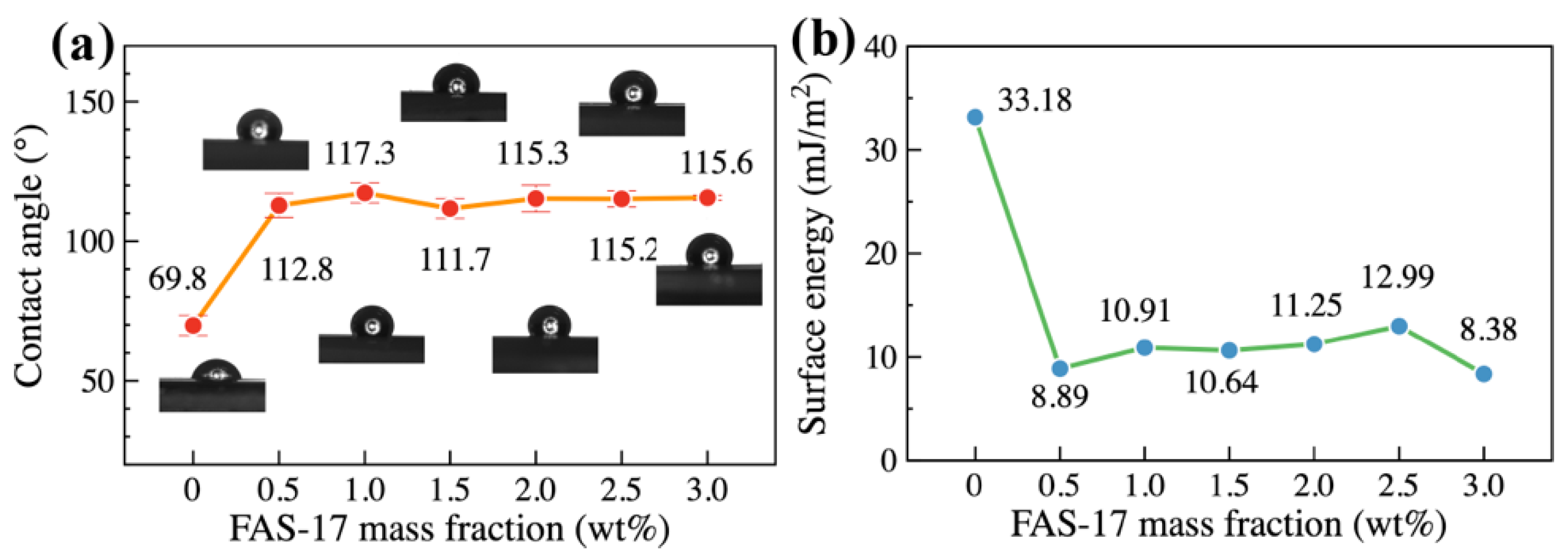
3.3. Static Water Repellency and Surface Energy
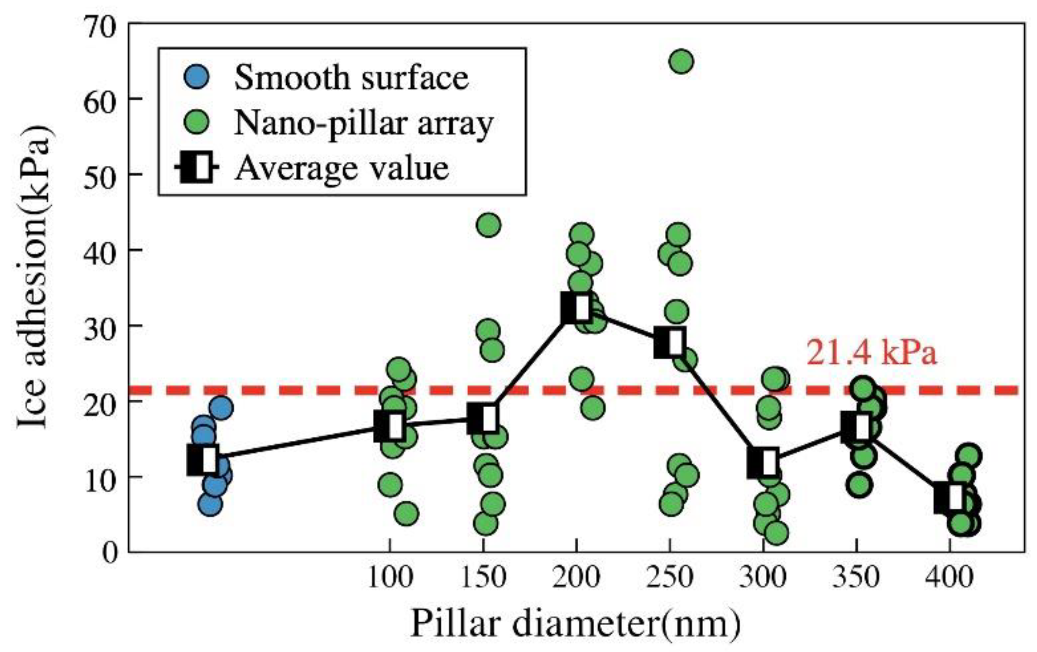
The relationship between the water contact angle and the FAS-17 mass fraction of the modified epoxy resin is illustrated in Figure 5a. The contact angle of cured resin without adding FAS-17 is about 69.8°, which belongs to the scope of the hydrophilic state. With the increase in the mass fraction of FAS-17 in the resin system, the water contact angle increases to 117.3°, and the intrinsic wetting likelihood of the resin surface converts into hydrophobicity. The introduction of FAS-17 has a significant influence on the chemical properties of the epoxy resin surface. When the mass fraction of FAS-17 increases from 0.5 to 3 wt %, the contact angle of water on the modified epoxy surface fluctuates within a small range. The hydrophobicity of the modified epoxy surface did not undergo significant alteration with the increase in the FAS-17 concentration. The reason for this is related to the curing kinetics of epoxy resin. Small molecules (methanol) are removed from the branches on the oxy resin side during the curing process. At the same time, the groups containing fluorine tend to move towards the surface spontaneously and reduce the surface energy. By curing at an ambient temperature of 60 °C, high ambient temperature intensifies the movement of molecular chains in the liquid state. A large number of groups containing fluorine gather on the resin surface. The groups on the surface significantly reduce the epoxy surface energy and increase the non-wettability. Subsequently, with the increase in the mass fraction of FAS-17, the change in contact angle was not obvious, the reason for which relates to the saturation distribution of groups containing fluorine on the epoxy surface.
The surface energy of resin under different FAS-17 mass fractions is shown in Figure 5b, which is calculated by a series of python codes with a two-liquid method, as presented in Appendix A. The surface energy of the resin without modification by fluorine-containing groups was 33.18 mJ/m2. On adding FAS-17, the surface energy of the modified resin decreased to 8.38 mJ/m2. The surface energy was only one-third of that before modification, which conforms to the surface concentrating phenomenon of fluorine, as illustrated in Figure 4. As the mass fraction of FAS-17 increases from 0.5 to 3.0 wt %, the surface energy is not significant and fluctuates in a small range. This means that persistently reducing surface energy by increasing the mass fraction of FAS-17 is not possible. The regularity is consistent with the tendency illustrated in Figure 3, further verifying the above conjecture.
Using AAO templates with the same nano-hole spacing distance (450 nm) and the different pore diameters of 100, 150, 200, 250, 300, 350, and 400 nm, 1 wt % FAS-17-modified epoxy resin was used to prepare nano-pillar arrays with different sizes. Figure 6a shows the contact angle of the unmodified epoxy resin array. With the increase in pillar diameter, the contact angle fluctuates in the range of 51.7° to 73.3°, which is generally lower than that for an unmodified smooth surface (69.8°). This is due to the introduction of nano-pillar arrays. The intrinsic hydrophilic epoxy resin shows a larger specific surface area, making it easier for liquids to infiltrate into the voids between nano-pillars. Figure 6b shows the contact angle on the modified epoxy resin surface with a nano-pillar array. The contact angle fluctuates in the range of 124.2° to 134.3°. Besides, nano-pillar arrays of different heights (400, 900, and 1500 nm) were prepared from templates to investigate the mechanism of the non-wettability and icephobic behavior affected by nano-structure height increase. Figure 6c shows the contact angle curve of the unmodified nano-pillar array epoxy resin surface. The contact angle fluctuates between 30.9° and 80.6°, appearing as the hydrophilic surface. The higher value (80.6°) is probably caused by mistake. Besides that, the contact angle at the nano-pillar array epoxy resin surface is much lower than that (69.8°) on a smooth epoxy surface. On the other hand, the contact angle on the modified surface illustrated in Figure 6d raises to 154.3° because of the combination of surface structure and the low surface energy effect.

3.4. Ice Adhesion

To further investigate the relationship between nano-structure morphology and icephobic performance, the ice adhesion strength was tested, and the results are illustrated in Figure 7. Ice adhesion strength on the smooth epoxy surface is 21.4 kPa, as shown with blue circles in Figure 7. Each circle represents an individual ice adhesion test. It decreases to 12.2 kPa after 1 wt % FAS-17 modification. The low surface energy effect causes a significant reduction after 1 wt % FAS-17 modification.
The ice adhesion strength of the modified epoxy resin surface is significantly changed under the nano-structure’s influence, showing a rising trend at the start and then a fall. The introduction of nano-structures does not always reduce the ice adhesion strength on the epoxy resin surface. Some data are even higher than that of the smooth epoxy resin surface without modification, caused by the severe interlock effect [31]. Still, with the increase in nano-pillar diameter, the ice adhesion strength shows a decreasing trend to as low as 7.3 kPa. The influence of the nano-structure’s interlock effect is significantly reduced, while the diameter of the nano-pillar further increases, as the epoxy array shows better elastic performance in the nano-scale and further induces the interface elastic mismatch effect [22,37,38].
The variation in ice adhesion strength shows a similar trend with the previously measured contact angle, which is correlated with the structure volume fraction of the nano-pillar arrays on the epoxy resin surface, as shown in Figure 8. Ice adhesion strength data for some samples have a large error, because the degree of the interlock effect could not be assessed during the freezing procedure. The ice adhesion strength displays an “M” shape similar to the non-wettability of the nano-pillar array epoxy resin surface, and the trend of the ice adhesion strength curve slightly lags behind the trend of the contact angle curve related to the different stress characteristics of ice and water [31]. As soon as the structure volume fraction of the nano-pillar array is close to 0 and greater than 70%, the nano-pillar array epoxy resin surface tends to display lower ice adhesion strength. The ice adhesions reach 16.7 and 7.3 kPa at the structure volume fractions of the nano-pillar of 4.5% and 71.7%, respectively, which are generally recognized as ultra-low ice adhesion strength [22,40]. The tendency of the results is similar to that obtained by micro-column arrays on silicon wafer [41], which implies a strong connection between micro- and nano-structured surfaces.
For the surfaces where micro- and nano-structures are relatively sparse, the volume expansion effect of the freezing process can make the ice inevitably fill in the voids between micro- and nano-structures [42], causing an interlocking effect on the micro- and nano-structure surface and making the de-icing procedure become more demanding on such hydrophobic surfaces [31,43,44], as shown in Figure 9a. Such a theory explains that ice adhesion strength increases on the epoxy resin surface. The nano-pillar array is relatively sparse, especially in the starting region of the ice adhesion strength curve shown in Figure 8. On such a surface, the nano-pillar array is too sparse. The liquid water droplet is conducive for infiltrating into the voids between nano-pillars, resulting in a lower contact angle. It is also easier for the ice frontier to fill into the voids with such a low structure volume fraction while freezing. In that condition, even the nano-pillar array has better elastic properties [38]. The interlocking effect on the sparse nano-pillar array will offset or partially offset the benefits of reducing the ice adhesion of the interface elastic mismatch effect.
When the structure volume fraction is close to 17.9% (the nano-pillar diameter is close to 200 nm), the ice adhesion strength on the surface increases up to 32.3 kPa, 2.64 times that of the smooth surface. When the structure volume fraction of the surface structure increased from 15% to 30%, the nano-structure still could not effectively prevent the ice front from filling the space in the nano-pillar array. The interlocking effect of ice filling in pillar voids weakened with the structure volume fraction of the nano-pillar rising. At the same time, due to the similarity of the structure volume fractions of ice and the structure volume fraction of the nano-pillar, the elastic mismatch effect, which causes the nano-crack initiator effect to decrease ice adhesion, was affected [22], resulting in relatively high ice adhesion strength.
When the volume fraction of the structure increased further, the smaller void fraction of the structure became conducive to reduction in ice growth in the voids during the droplet freezing procedure, as illustrated in Figure 9b. Moreover, with the structure volume fraction rising further, the mechanical mechanism of the solid–ice interface was dominated by the elastic mismatch effect, presenting the nano-crack initiator’s role during ice stripping, resulting in extremely low ice adhesion strength (7.3 kPa; structure volume fraction of around 71.7%).
Besides the research regarding ice adhesion behavior under different structure volume fractions, the ice adhesion strength affected by the height of the nano-pillar structure was also studied. AAO templates control the pillar diameter with a pore diameter of 300 nm and a pore distance of 450nm. The ice adhesion strength on the nano-pillar array epoxy surface shows a pronounced downtrend with the height of the nano-pillar increasing, as low as 7.0 kPa. The downtrend illustrated in Figure 10 is in accordance with the previously reported laws [41,45]. It is well accepted that the ice adhesion strength decreases with the increase in the height of the hydrophobic nano-pillar, as illustrated in Figure 9c. Moreover, with the understanding of the height of nanoscale structure affecting the ice adhesion, we predict that a higher nano-structure height will facilitate lower ice adhesion strength on the nano-pillar epoxy surface.

4. Conclusions

In summary, we constructed a series of nano-pillar array epoxy resin surfaces from AAO membranes with nano-structured templates. The nano-pillar arrays fabricated on the epoxy surface provided excellent non-wettability and a contact angle of up to 154.3°. The ice adhesion strength on the nano-pillar array epoxy surface could be reduced to 7.0 kPa, which is a 24% reduction when compared to smooth surfaces. This therefore proves to be a potential method for weakening or neutralizing the interlock effect which blocks the development of icephobic materials. Moreover, the solid–ice interface mechanism induced by the synergistic effect of non-wetting behavior and the nano-crack initiator effect is discussed. The interlock effect, causing the high ice adhesion, drops with the rise in the nano-pillar structure volume fraction, giving theoretical insights into the feasibility of tactics to reduce the ice adhesion strength on such hydrophobic/superhydrophobic resin surfaces. The results provide great support to the research of passive anti-icing techniques, especially for epoxy matrix composite materials.

Supplementary Materials

The following are available online at https://www.mdpi.com/2079-6412/10/11/1043/s1, Table S1: The geometry characteristics of the AAO template and nano-pillar EP surface (various in diameter). Table S2: The geometry characteristics of the AAO template and nano-pillar EP surface (various in depth and height). Figure S1: The SEM images of the AAO templates. (a–g) The pore structured AAO templates with a pore diameter of 100, 150, 200 250, 300, 350 and 400 nm; (h) the AAO template with a pore depth of 900 nm. Figure S2: The SEM images of the nano-pillar array epoxy with a pillar diameter of (a) 100 nm, (b) 150 nm, (c) 200 nm, (d) 250 nm, (e) 300 nm, (f) 350 nm, and (g) 400 nm. Figure S3: The SEM images of the nano-pillar array epoxy with a pillar height of (a) 400 nm, (b) 900 nm, and (c) 1500 nm; Figure S4: FTIR spectra of epoxy resin before and after curing. Appendix A.

Author Contributions

Conceptualization, J.T. and Y.S.; methodology, Z.J.; software, Y.Z.; validation, Z.J., H.C., Z.W., and Y.Z.; writing—original draft preparation, Z.J.; writing—review and editing, Y.S.; visualization, Z.J. and Y.L.; supervision, J.T.; funding acquisition, Y.S. and J.T. All authors have read and agreed to the published version of the manuscript.

Funding

This research was supported by the National Natural Science Foundation of China (Nos. 52075246, 51671105 and 51705244), the Natural Science Foundation of Jiangsu Province (No. BK20170790), the Project Funded by China Postdoctoral Science Foundation (No. 2019M661826), General Project of Zhejiang Provincial Department of Education (Y201737320), the NUAA Innovation Program for Graduate Education (kfjj20190617), and the Project Funded by the Priority Academic Program Development of Jiangsu Higher Education Institutions.

Conflicts of Interest

The funders had no role in the design of the study; in the collection, analyses, or interpretation of data; in the writing of the manuscript, or in the decision to publish the results.

References

  1. Tetteh:, E.; Loth, E. Reducing Static and Impact Ice Adhesion with a Self-Lubricating Icephobic Coating (SLIC). Coatings 2020, 10, 262. [Google Scholar] [CrossRef] [Green Version]
  2. Qin, C.; Mulroney, A.T.; Gupta, M.C. Anti-icing epoxy resin surface modified by spray coating of PTFE Teflon particles for wind turbine blades. Mater. Today Commun. 2020, 22, 7. [Google Scholar] [CrossRef]
  3. Shen, Y.; Wu, X.; Tao, J.; Zhu, C.; Lai, Y.; Chen, Z. Icephobic materials: Fundamentals, performance evaluation, and applications. Prog. Mater. Sci. 2019, 103, 509–557. [Google Scholar] [CrossRef]
  4. Farzaneh, M.; Ryerson, C.C. Anti-icing and deicing techniques. Cold Reg. Sci. Technol. 2011, 65, 1–4. [Google Scholar] [CrossRef]
  5. Kreder, M.J.; Alvarenga, J.; Kim, P.; Aizenberg, J. Design of anti-icing surfaces: Smooth, textured or slippery? Nat. Rev. Mater. 2016, 1, 1–15. [Google Scholar] [CrossRef]
  6. Feng, L.; Li, S.H.; Li, Y.; Li, H.J.; Zhu, D.B. Super-hydrophobic Surfaces: From Natural to Artificial. Adv. Mater. 2010, 14, 1857–1860. [Google Scholar] [CrossRef]
  7. Wang, D.; Sun, Q.; Hokkanen, M.J.; Zhang, C.; Lin, F.-Y.; Liu, Q.; Zhu, S.-P.; Zhou, T.; Chang, Q.; He, B.; et al. Design of robust superhydrophobic surfaces. Nature 2020, 582, 55–59. [Google Scholar] [CrossRef] [PubMed]
  8. Neinhuis, W.B. Purity of the sacred lotus, or escape from contamination in biological surfaces. Planta 1997, 202, 1–8. [Google Scholar]
  9. Huang, Z.-S.; Quan, Y.-Y.; Mao, J.-J.; Wang, Y.-L.; Lai, Y.; Zheng, J.; Chen, Z.; Wei, K.; Li, H. Multifunctional superhydrophobic composite materials with remarkable mechanochemical robustness, stain repellency, oil-water separation and sound-absorption properties. Chem. Eng. J. 2019, 358, 1610–1619. [Google Scholar] [CrossRef]
  10. Khedir, K.R.; Kannarpady, G.K.; Ryerson, C.; Biris, A.S. An outlook on tunable superhydrophobic nanostructural surfaces and their possible impact on ice mitigation. Prog. Org. Coat. 2017, 112, 304–318. [Google Scholar] [CrossRef]
  11. Shen, Y.; Wang, G.; Tao, J.; Zhu, C.; Liu, S.; Jin, M.; Xie, Y.; Chen, Z. Anti-Icing Performance of Superhydrophobic Texture Surfaces Depending on Reference Environments. Adv. Mater. Interfaces 2017, 4, 1700836. [Google Scholar] [CrossRef]
  12. Farhadi, S.; Farzaneh, M.; Kulinich, S.A. Anti-icing performance of superhydrophobic surfaces. Appl. Surf. Sci. 2011, 257, 6264–6269. [Google Scholar] [CrossRef]
  13. Ge, M.; Cao, C.; Liang, F.; Liu, R.; Zhang, Y.; Zhang, W.; Zhu, T.; Yi, B.; Tang, Y.; Lai, Y. A “PDMS-in-water” emulsion enables mechanochemically robust superhydrophobic surfaces with self-healing nature. Nanoscale Horiz. 2020, 5, 65–73. [Google Scholar] [CrossRef]
  14. Hao, P.; Lv, C.; Zhang, X. Freezing of sessile water droplets on surfaces with various roughness and wettability. Appl. Phys. Lett. 2014, 104, 161609. [Google Scholar] [CrossRef]
  15. Xu, J.J.; Jing, R.N.; Ren, X.Y.; Gao, G.H. Fish-inspired anti-icing hydrogel sensors with low-temperature adhesion and toughness. J. Mater. Chem. A 2020, 8, 9373–9381. [Google Scholar] [CrossRef]
  16. Dou, R.; Chen, J.; Zhang, Y.; Wang, X.; Cui, D.; Song, Y.; Jiang, L.; Wang, J. Anti-icing Coating with an Aqueous Lubricating Layer. ACS Appl. Mater. Interfaces 2014, 6, 6998–7003. [Google Scholar] [CrossRef] [PubMed]
  17. Kim, P.; Wong, T.S.; Alvarenga, J.; Kreder, M.J.; Adorno-Martinez, W.E.; Aizenberg, J. Liquid-Infused Nanostructured Surfaces with Extreme Anti-Ice and Anti-Frost Performance. ACS Nano 2012, 6, 6569–6577. [Google Scholar] [CrossRef] [PubMed]
  18. Li, T.; Zhuo, Y.; Hakonsen, V.; Ronneberg, S.; He, J.; Zhang, Z. Epidermal Gland Inspired Self-Repairing Slippery Lubricant-Infused Porous Coatings with Durable Low Ice Adhesion. Coatings 2019, 9, 602. [Google Scholar] [CrossRef] [Green Version]
  19. Li, T.; Ibáñez-Ibáñez, P.F.; Håkonsen, V.; Wu, J.; Xu, K.; Zhuo, Y.; Luo, S.; He, J.; Zhang, Z. Self-Deicing Electrolyte Hydrogel Surfaces with Pa-level Ice Adhesion and Durable Antifreezing/Antifrost Performance. ACS Appl. Mater. Inter. 2020, 12, 35572–35578. [Google Scholar] [CrossRef] [PubMed]
  20. Cao, L.; Jones, A.K.; Sikka, V.K.; Wu, J.; Gao, D. Anti-Icing Superhydrophobic Coatings. Langmuir 2009, 25, 12444–12448. [Google Scholar] [CrossRef]
  21. Piscitelli, F.; Chiariello, A.; Dabkowski, D.; Corraro, G.; Marra, F.; Di Palma, L. Superhydrophobic Coatings as Anti-Icing Systems for Small Aircraft. Aerospace 2020, 7, 2. [Google Scholar] [CrossRef] [Green Version]
  22. He, Z.W.; Xiao, S.B.; Gao, H.J.; He, J.Y.; Zhang, Z.L. Multiscale crack initiator promoted super-low ice adhesion surfaces. Soft Matter 2017, 13, 6562–6568. [Google Scholar] [CrossRef]
  23. Golovin, K.; Dhyani, A.; Thouless, M.D.; Tuteja, A. Low-interfacial toughness materials for effective large-scale deicing. Science 2019, 364, 371–375. [Google Scholar] [CrossRef] [PubMed]
  24. Fu, J.; Wang, Y.K.; Yang, M.T.; Desai, R.A.; Chen, C.S. Mechanical regulation of cell function with geometrically modulated elastomeric substrates. Nat. Methods 2010, 7, 733–736. [Google Scholar] [CrossRef] [PubMed]
  25. Zhu, T.; Cheng, Y.; Huang, J.; Xiong, J.; Ge, M.; Mao, J.; Liu, Z.; Dong, X.; Chen, Z.; Lai, Y. A transparent superhydrophobic coating with mechanochemical robustness for anti-icing, photocatalysis and self-cleaning. Chem. Eng. J. 2020, 399, 125746. [Google Scholar] [CrossRef]
  26. Xu, X.W.; Jerca, V.V.; Hoogenboom, R. Bio-inspired Hydrogels as Multi-task Anti-icing Hydrogel Coatings. Chem 2020, 6, 820–822. [Google Scholar] [CrossRef] [Green Version]
  27. Mielonen, K.; Pakkanen, T.A. Superhydrophobic hierarchical three-level structures on 3D polypropylene surfaces. J. Micromech. Microeng. 2019, 29, 025006. [Google Scholar] [CrossRef]
  28. Nguyen, T.-B.; Park, S.; Lim, H. Effects of morphology parameters on anti-icing performance in superhydrophobic surfaces. Appl. Surf. Sci. 2018, 435, 585–591. [Google Scholar] [CrossRef]
  29. Jin, M.; Shen, Y.; Luo, X.; Tao, J.; Xie, Y.; Chen, H.; Wu, Y. A combination structure of microblock and nanohair fabricated by chemical etching for excellent water repellency and icephobicity. Appl. Surf. Sci. 2018, 455, 883–890. [Google Scholar] [CrossRef]
  30. Shen, Y.; Xie, X.; Xie, Y.; Tao, J.; Xu, Y. Statistically understanding the roles of nanostructure features in interfacial ice nucleation for enhancing icing delay performance. Phys. Chem. Chem. Phys. 2019, 21. [Google Scholar] [CrossRef]
  31. Nosonovsky, M.; Hejazi, V. Why Superhydrophobic Surfaces Are Not Always Icephobic. ACS Nano 2012, 6, 8488–8491. [Google Scholar] [CrossRef] [PubMed]
  32. Kulinich, S.A.; Farhadi, S.; Nose, K.; Du, X.W. Superhydrophobic Surfaces: Are They Really Ice-Repellent? Langmuir 2011, 27, 25–29. [Google Scholar] [CrossRef] [PubMed]
  33. He, M.; Li, H.; Wang, J.; Song, Y. Superhydrophobic surface at low surface temperature. Appl. Phys. Lett. 2011, 98, 093118. [Google Scholar] [CrossRef]
  34. Chen, J.; Liu, J.; He, M.; Li, K.Y.; Cui, D.P.; Zhang, Q.L.; Zeng, X.P.; Zhang, Y.F.; Wang, J.J.; Song, Y.L. Superhydrophobic surfaces cannot reduce ice adhesion. Appl. Phys. Lett. 2012, 101, 3. [Google Scholar] [CrossRef]
  35. Liu, F.; Wang, Z.; Pan, Q. Intelligent Icephobic Surface toward Self-Deicing Capability. ACS Sustain. Chem. Eng. 2020, 8, 792–799. [Google Scholar] [CrossRef]
  36. Ryzhkin, I.A.; Petrenko, V.F. Physical mechanisms responsible for ice adhesion. J. Phys. Chem. B 1997, 101, 6267–6270. [Google Scholar] [CrossRef]
  37. Cho, Y.; Minsky, H.K.; Jiang, Y.; Yin, K.; Turner, K.T.; Yang, S. Shear Adhesion of Tapered Nanopillar Arrays. ACS Appl. Mater. Inter. 2018, 10, 11391–11397. [Google Scholar] [CrossRef]
  38. Cho, Y.; Kim, G.; Cho, Y.; Lee, S.Y.; Minsky, H.; Turner, K.T.; Gianola, D.S.; Yang, S. Orthogonal Control of Stability and Tunable Dry Adhesion by Tailoring the Shape of Tapered Nanopillar Arrays. Adv. Mater. 2016, 27, 7788–7793. [Google Scholar] [CrossRef]
  39. Fu, Q.T.; Wu, X.H.; Kumar, D.; Ho, J.W.C.; Kanhere, P.D.; Srikanth, N.; Liu, E.J.; Wilson, P.; Chen, Z. Development of Sol-Gel Icephobic Coatings: Effect of Surface Roughness and Surface Energy. ACS Appl. Mater. Inter. 2014, 6, 20685–20692. [Google Scholar] [CrossRef]
  40. Guo, P.; Zheng, Y.; Wen, M.; Song, C.; Lin, Y.; Jiang, L. Icephobic/Anti-Icing Properties of Micro/Nanostructured Surfaces. Adv. Mater. 2012, 24, 2642–2648. [Google Scholar] [CrossRef]
  41. Hou, W.; Shen, Y.; Tao, J.; Xu, Y.; Jia, Z. Anti-icing performance of the superhydrophobic surface with micro-cubic array structures fabricated by plasma etching. Colloids Surf. A Physicochem. Eng. Asp. 2019, 586, 124180. [Google Scholar] [CrossRef]
  42. Ronneberg, S.; Xiao, S.B.; He, J.Y.; Zhang, Z.L. Nanoscale Correlations of Ice Adhesion Strength and Water Contact Angle. Coatings 2020, 10, 379. [Google Scholar] [CrossRef]
  43. Sojoudi, H.; McKinley, G.H.; Gleason, K.K. Linker-free grafting of fluorinated polymeric cross-linked network bilayers for durable reduction of ice adhesion. Mater. Horiz. 2015, 2, 91–99. [Google Scholar] [CrossRef] [Green Version]
  44. He, Y.; Jiang, C.Y.; Cao, X.B.; Chen, J.; Tian, W.; Yuan, W.Z. Reducing ice adhesion by hierarchical micro-nano-pillars. Appl. Surf. Sci. 2014, 305, 589–595. [Google Scholar] [CrossRef]
  45. Jeon, J.; Jang, H.; Chang, J.; Lee, K.-S.; Rip Kim, D. Fabrication of Micro-Patterned Aluminum Surfaces for Low Ice Adhesion Strength. Appl. Surf. Sci. 2018, 440, 643–650. [Google Scholar] [CrossRef]
Figure 1. Schematic presentation of the fabrication process of the nano-pillar structured EP surface.
Coatings 10 01043 g001
Figure 2. SEM images of the anodic aluminum oxide (AAO) template and the as-constructed nano-pillar structured EP surface (d = 290 nm): (a) AAO template; (b) nano-pillar EP array.
Coatings 10 01043 g002
Figure 3. The FTIR spectra of the modified epoxy resin with mass fractions of FAS-17 of 0, 0.5, 1, 1.5, 2, 2.5, and 3 wt %.
Coatings 10 01043 g003
Figure 4. The EDS data of the epoxy surface before and after the addition of 1 wt % FAS-17: (a) EP, (b) F-EP (fluoridated epoxy).
Coatings 10 01043 g004
Figure 5. The contact angle (CA) and the surface energy of FAS-17-modified epoxy: (a) The water contact angle of epoxy modified with the FAS-17 mass fraction; (b) Surface energy of the epoxy resin modified with the FAS-17 mass fraction.
Coatings 10 01043 g005
Figure 6. Water contact angle on the epoxy surface before and after modification: (a) Water contact angle on the pillar-structured epoxy with a pillar diameter in the range of 100–400 nm. The pillar heights are controlled by AAO templates with a pore depth of 500 nm. (b) Water contact angle on the pillar-structured F-epoxy (1 wt %) with a pillar diameter in the range of 100–400 nm. The pillar heights are controlled by AAO templates with a pore depth of 500 nm. (c) Water contact angle on the pillar-structure epoxy with a pillar height in the range of 400–1500 nm. The pillar diameters are controlled by AAO templates with a pore diameter of 300 nm, and the AAO templates control the pore distance of 450 nm. (d) Water contact angle on the pillar-structured F-epoxy (1 wt %) with a pillar height in the range of 400–1500 nm. Pillar diameter with a pore diameter of 300 nm and a pore distance of 450 nm.
Coatings 10 01043 g006
Figure 7. Ice adhesion of the hydrophobic nano-pillar array-fluoridated epoxy (1 wt %).
Coatings 10 01043 g007
Figure 8. The ice adhesion and the contact angle of the hydrophobic nano-pillar array-fluoridated epoxy (1 wt %) plot at a volume fraction of nano-pillar structure on the epoxy surface.
Coatings 10 01043 g008
Figure 9. Illustrations of the ice adhesion mechanism of the hydrophobic nano-structure array on fluoridated epoxy (1 wt %): (a) The icing and de-icing process on the nano-pillar array EP surface; (b) the ice adhesion behavior under different structure volume fractions of nano-pillar arrays; (c) the ice adhesion strength under different heights of nano-pillar arrays.
Coatings 10 01043 g009
Figure 10. The ice adhesion of hydrophobic nano-pillar array fluoridated epoxy (1 wt %).
Coatings 10 01043 g010
Publisher’s Note: MDPI stays neutral with regard to jurisdictional claims in published maps and institutional affiliations.

