Microstructure Evolution and Properties of Laser Cladding CoCrFeNiTiAlx High-Entropy Alloy Coatings
by
Yiku Xu
1,*, 
Zhiyuan Li
1,
Jianru Liu
1,
Yongnan Chen
1,*,
Fengying Zhang
1,
Lei Wu
1,
Jianmin Hao
1 and
Lin Liu
2 1
School of Material Science and Engineering, Chang’an University, Xi’an 710064, China
2
State Key Laboratory of Solidification and Processing, Northwestern Polytechnical University, Xi’an 710072, China
*
Authors to whom correspondence should be addressed.
Coatings 2020, 10(4), 373; https://doi.org/10.3390/coatings10040373
Submission received: 26 February 2020
/
Revised: 5 April 2020
/
Accepted: 7 April 2020
/
Published: 9 April 2020
(This article belongs to the Special Issue Manufacturing and Surface Engineering II)
Abstract
:High-entropy alloy (HEA) coatings of CoCrFeNiTiAlx (x = 0, 0.5, 1, 1.5, 2) were prepared on the surface of AISI1045 steel by laser cladding. The effects of the Al content on the microstructure, composition, phase constitution, and wear and corrosion resistance of the coatings were investigated. The results showed that when increasing the Al element content from 0 to 0.5, the phase constitution of the CoCrFeNiTiAlx coating changed from a single Face-centered cubic (FCC) phase to Body-centered cubic 1 (BCC1) and Body-centered cubic 2 (BCC2) phases, with a small amount of Laves phase, which obviously improved the friction and corrosion resistance of the coating. With further enhancing of the Al content, the amount of BCC1 phase increased, while the BCC2 phase and the Laves phase decreased. The CoCrFeNiTiAl2 HEA coating transformed into a single BCC1 phase, with retrogressive wear and corrosion resistance. It was found that the Al0.5 alloy coating exhibits excellent wear resistance, high hardness, and corrosion resistance in a 3.5 wt.% NaCl solution. Furthermore, the effect of the Al content on the microstructure, phase, and the relating properties of the CoCrFeNiTiAlx HEA coatings is also discussed.
1. Introduction
Traditional alloy design considers that the presence of multiple elements in an alloy results in the formation of intermetallic compounds (IMCs), which is detrimental to alloy performance. However, Ye JW proposed the concept of high-entropy alloys (HEAs) in 2004 [1]. An HEA is composed of five or more constituent elements, as per the mole ratio or the nearly mole ratio. The design principle prioritizes the high entropy effect, which inhibits the formation of brittle IMCs with complex crystal structures, instead forming a simple type of alloy solid solution phase [2]. The formation of high-entropy solid solution alloys must satisfy certain conditions. Zhang et al. used three main parameters (8.5 ≥ δ ≥ 0, 7 kJ/mol ≥ ΔHmix ≥ −22 kJ/mol, and 19.5 J/(K·mol) ≥ ΔSmix ≥ 11 J/(K·mol)) to characterize the common behavior of constituent elements in HEAs [3]. They are atomic size difference δ, mixing enthalpy ΔHmix, and mixing entropy ΔSmix, and their respective expressions are:
A lot of research has reported HEAs with excellent hardness, strength, and corrosion and wear resistances [2,3,4,5,6], a typical example being that of the CoCrFeNi HEA system. For example, CoCrFeNiMn HEA has higher yield strength (518 MPa) and ultimate tensile strength (660 MPa), and the maximum yield strength of Al0.7CoCrFeNi HEA is 1022 MPa [7,8]. Due to their excellent performance, HEA coatings are also prepared to protect the substrates in different ways. The commonly used processes for preparing alloy coatings are plasma spraying and high-velocity oxygen fuel (HVOF) spraying [9,10,11]. However, recently, the process of preparing alloy coating by laser cladding has become common [12,13]. Laser cladding is characterized by high energy density, fast heating and cooling rates, a lower heat effect on the base material, and a low dilution rate. The coating microstructure is of lower uniform density and micro-defects and forms excellent metallurgical bonds with the matrix material independent of size [14], Matilainen et al. prepared AlCoCrFeNi HEAs by laser additive manufacturing, and it is found that the solidification rate is a very important factor that determines the existence and distribution of phases in AlCoCrFeNi HEA, fast solidification substantially increases the preference for the BCC phase with a corresponding substantial increase in hardness. It should be noted that this is also related to some parameters such as specific powder, laser beam speed, and power density [15].
As reported, the key factor affecting the alloying behavior and properties of HEA is its elemental composition design. Al and Ti have been investigated in many articles involving HEA due to the larger atomic radius and characteristics of these elements having greater impact on the structural property characteristic of HEAs [12,16,17,18,19]. Liu et al. prepared an AlCoCrFeNiTix (x = 0, 0.2, 0.4, 0.6, 0.8, 1.0) coating on AISI1045 steel by laser cladding technology and studied the corrosion behavior of the HEA coating in a 3.5 wt.% NaCl solution. The results proved that the introduction of Ti improves the corrosion resistance of the coating [12]. Zhang et al. used laser cladding technology to prepare a FeCoCrAlNi HEA coating on 304 stainless steel, which exhibited good corrosion resistance and microhardness [13]. However, Kao et al. studied the corrosion resistance of AlxCoCrFeNi HEA and found that the self-corrosion potential (Ecorr) and self-corrosion current (Icorr) were independent of the Al content [20], which conflicts with previous studies. Thus, it is important to study the effect of additive elements for better understanding the HEA systems.
In this work, CoCrFeNiTiAlx HEA coatings were prepared using laser cladding technology. The performance of the as-prepared HEA coatings and the effect of Al content on the microstructure, phase constitution, and wear and corrosion resistance of the coatings were investigated.
2. Materials and Methods
AISI1045 steel with dimensions of 80 by 60 by 10 mm3 was selected as the substrate. It was cleaned with absolute ethanol as the pretreatment in order to guarantee high matrix-coating bonds. Commercial Co, Cr, Fe, Ni, Ti, and Al powders with purities higher than 99.9 wt.% were used as raw materials. The particle sizes of the powders were determined to be 75–100 μm. The powders were weighed according to the nominal composition of CoCrFeNiTiAlx (x = 0, 0.5, 1, 1.5, 2 in molar ratio) using a precise electronic balance, the quality of each component is shown in Table 1. To ensure uniform mixing of the HEA powder during cladding, the ball-to-powder ratio (mass ratio) was set to 2:1 and mixed at a speed of 300 r/min in a QE-04 planetary ball mill for an hour. Then, a single lap multi-layer of laser cladding feeding powder was carried out under an argon atmosphere with an LSF-SI6000A equipment (BLT, Xian, China), as shown in Figure 1. The specific process parameters are listed in Table 2.
After laser cladding, the prepared coating material was sectioned into samples measuring 8 by 8 by 4 mm3 using a wire electric discharge machine. The samples were ground and polished using a polishing machine. The microstructure of the HEA coatings was observed by the Hitachi S-4800 cold field emission scanning electron microscope (SEM, Hitachi, Tokyo, Japan) applying an energy dispersive spectrometer (EDS, Hitachi, Tokyo, Japan) to determine the element composition and the field emission transmission electron microscope (TEM, FEI, Hillsboro, OR, USA) Talos F200X. The phase constitution was determined using X-ray diffraction (Bruker D8 Advance model), using Cu–Kα radiation scanning from 30° to 90° at a scanning rate of 8° min−1, the volume fraction of the phases was calculated by using Image-Pro Plus software (Image-Pro Plus 6.0). The microhardness of the sample was measured using a microhardness tester (HV-1000A, Shanghai Optical Instrument Factory, Shanghai, China) with a load value of 200 g and a holding time of 10 s. The average value of seven different points was taken as the hardness of the sample. Before the friction and abrasion test, the mass of each sample was weighed by an electronic balance. At room temperature and air relative humidity of 25%–30%, the friction and wear behavior of the coating was evaluated using a pin-disk wear machine (MMQ-02G, KASON, Jinan, China). The GCr15 bearing steel ball with a diameter of 6 mm was selected as the abrasive material, and the prepared sample was fixed on the disk of the worktable. The GCr15 bearing steel ball started the friction and wear test at the center of the sample. The process parameters are as follows: The load is 10 N, the speed is 100 r/min, and the time is 15 min. Considering that the initial stage of the friction and wear test did not reach a stable state, we took the value in the interval of 301 s–900 s to calculate the average friction coefficient. After the friction coefficient measurement was completed, the mass of each sample after the friction test was re-weighed. The corrosion behavior of the HEA coating in a 3.5 wt.% NaCl solution was studied by using an electrochemical workstation. The sample to be tested was used as a working electrode (WE), with the platinum plate electrode used as a counter electrode (CE), and a saturated calomel electrode (Hg/Hg2Cl2 saturated KCl) used as a reference electrode (RE). The potential scanning speed was 2 mV/s during the test, at a scanning range of approximately −1.5 to 0.5 V. The corrosion current density (Icoor) and self-corrosion potential (Ecoor) were obtained by fitting the test results using the CorShow software (CorShow software 1.1.16).
3. Results and Discussion
3.1. Phase Constitution
Figure 2 shows the XRD diffraction patterns of the as-prepared laser cladding CoCrFeNiTiAlx HEA coatings with different Al contents. The Al0 coating was composed of a single FCC solid solution phase. When increasing the molar ratio of Al (x = 0.5–1.5), the phase constitution of the coatings change from a single FCC phase to two BCC (BCC1 and BCC2) phases, and a small amount of Laves phase peaks can also be found. As can be seen with the increased Al content, the intensity of the diffraction peak of the BCC2 phase and the Laves phase begin to weaken, and simultaneously, the BCC1 phase peak increases. The Al2 alloy coating transforms to a single phase with the BCC1 crystal structure. Using JADE software analysis, the BCC1 and BCC2 phases were identified as the Al–Ni phase and the Fe–Cr phase, and the Laves phase was identified as FeTi type, respectively.
3.2. Microstructure Evolution
The microstructures of the CoCrFeNiTiAlx high-entropy alloy coatings are shown in Figure 3. The Al0 coating in Figure 3a has a uniform single-phase structure with tiny voids, which is consistent with the XRD results. The laser cladding technology is characterized by rapid heating/cooling, which results in poor diffusion during the solidification process that prevents a small amount of gas from escaping when the molten pool solidifies, generating a small number of voids. The Al0.5 coating shows a typical dendritic crystal, consisting of the dendritic region (DR) and interdendritic region (ID). With the increase of Al content, the number of dendrites gradually increases and the distance between dendrites becomes smaller. This is attributed to the introduction of Al with a relatively larger atomic radius, which leads to grain refinement. When the Al content increases to two, the alloy coating exhibits a uniform BCC1 phase structure. Compared to Al0.5 in Figure 3a, the Al2 coating shows more defects, such as the voids indicated by the arrows. Figure 3 proves that the Al content significantly influences the microstructure evolution of the CoCrFeNiTiAlx high-entropy alloy coatings.
Figure 4a illustrates the morphology of a cross-section of the Al0.5 coating. It can be seen that three zones comprise the cross-section, including the substrate, the heat-affected zone (HAZ), and the HEA coating (HEAC). The dilution rate of the coating can be calculated by Equation (4):
where η is the dilution rate, h is the substrate penetration, and H is the cladding layer width, coating dilution rate is 32.93%, the combination of the coating and substrate is metallurgical and continuous. Due to the dilution effect of the Fe element in the matrix, the content of each alloy element in the composition transition region significantly deviates from the nominal composition proved by the EDS line scan result. This dilution phenomenon generally affects the whole HAZ zone of the coating. As the distance increases from the substrate to the HEAC, the content of each element gradually approaches the nominal composition.
Elemental distribution maps of Al0.5 HEA coating are illustrated in Figure 4b. It can be found that the DR is rich in Ni and Al elements, while the IR is rich in Fe and Cr elements. It has been reported that among multi-element metal elements, the more negative the mixing enthalpy, the greater the affinity between the two atoms, the more positive the mixing enthalpy, and the smaller the affinity [2,3,21]. According to the molar mixing enthalpy among the six elements shown in Table 3, the mixing enthalpy of Fe and Cr with the other five elements presents as the most positive, which signifies relatively small affinity. Consequently, when solidified, Fe and Cr elements are more easily repelled to the interdendritic region.
3.3. Microhardness
The results of the microhardness test of the CoCrFeNiTiAlx HEA coatings are shown in Figure 5. The hardness distribution curves are divided into three parts in a step shape—the HEA coatings, the HAZ, and the substrate. The thickness of the coating is ~3.5 mm, compared with 2.5 mm of the HAZ. From the HEA coatings to the substrate, the hardness distribution shows a downward trend, and the decreasing interval is concentrated in the heat-affected zone. The Al0.5 coating shows the highest hardness value of about 880 HV, which is 6.5 times as much as the substrate.
3.4. Friction and Wear
The curves of the friction coefficients versus the sliding time acquired from the substrate and the CoCrFeNiTiAlx HEA coatings against the steel ball are shown in Figure 6a. All of the curves consist of a running-in stage initially, which is a process of removing the surface roughness and flattening the uneven surface with relatively small contact areas between the worn surface and the counterpart of the steel ball. After the rough initial surface becomes smooth, the wear enters a stable stage, exhibiting a stable friction coefficient. The average friction coefficient of the substrate is the largest, which is 0.54, and the Al0 coating is also at a high level with an average friction coefficient of 0.42. It is obvious that, along with the addition of Al, the friction coefficient decreases sharply. The Al0.5 HEA coating exhibits the smallest friction coefficient of about 0.28, compared with the Al1, Al1.5, and Al2 coatings of about 0.31, 0.33, and 0.35, respectively.
The surface morphology of the coatings and substrate after wear are shown in Figure 6b. As can be seen, the substrate has the widest and deepest wear track, indicating its poor resistance to wear. Yet many furrows formed in the worn surface of the Al0 coating, which may be due to the coating and abrasive ball being slightly adhered in the early stages of wear. The generated abrasive debris, the coating, and the abrasive material formed the three-body wear, indicating the abrasive wear mechanism of the Al0 coating. The wear result of the Al0.5 coating shows no furrows existing on the wear surface, and only slight adhesive wear occurred. With increasing Al content, the wear of the Al1 and Al1.5 coatings becomes more serious. The number of furrows and the depth increase, and the wear mechanism changes to micro-abrasive wear. In comparison, the wear morphology of the Al2 coating emerges as obvious spalling, thus the wear mechanism of the Al2 coating can be deduced to be micro-fracture (flake) wear.
The wear mass loss of the CoCrFeNiTiAlx high-entropy alloy coating and the substrate is also presented in Figure 6c. The wear amount of the Al0 coating is 4.4 mg, and that of the Al0.5 coating suddenly drops to 2.9 mg, reaching its minimum value. As the Al content increases, the wear amount of the Al1, Al1.5, and Al2 coatings become 3.7 mg, 4.0 mg, and 4.2 mg, respectively. However, the wear of the five HEA coatings is still significantly lower than that of the substrate (19.7 mg). The Archard wear equation is an equation derived from a simplified model of abrasive wear, and although it does not take into account factors such as work hardening and frictional heat, it links the wear rate with the engineering variables and mechanical properties of the material. The expression of the Archard wear equation is [22]
where Wv is the volume wear, S is the sliding distance, F is the normal load, H is the hardness of the wear material, and K is the wear coefficient. According to the previous microhardness tests, the microhardness descends in the order of Al0.5, Al1, Al1.5, Al2, and Al0, AISI1045 steel. The relationship between hardness and the amount of wear is inverse: The higher the hardness, the lower the wear. The experimental results are consistent with Archard’s theoretical equations. Under the same wear condition, the wear rate of the as-prepared coatings is proportional to the friction coefficient and inversely proportional to the hardness.
3.5. Corrosion Resistance
The potential dynamic polarization curve of the CoCrFeNiTiAlx HEA coatings and substrate in a 3.5 wt.% NaCl solution is shown in Figure 7. The corrosion dynamics parameters obtained using the Tafel epitaxy are shown in Table 4. The self-corrosion potential of the substrate is −0.9701 V, which is lower than the self-corrosion potential of the coating, and the self-corrosion current density is the largest, reaching 4.71 × 10⁻⁵ A·cm−2. When increasing the Al content from 0 to 2, the corrosion resistance of the CoCrFeNiTiAlx HEA coating gradually increases, and then decreases. The Al0.5 coating shows the best corrosion resistance; the maximum self-corrosion potential is −0.5766 V, and the minimum self-corrosion current density is 9.13 × 10⁻⁷ A·cm−2.
3.6. Discussion
It has been reported that the addition of Al can change the phase constitution and the microstructure of HEA [16,17,18]. Figure 8a displays the TEM bright-field image of the Al0.5 coating. The EDS mapping in Figure 8d proves that the white area is rich in Fe and Cr elements, while the gray area is rich in Al and Ni elements. Being consistent with the XRD result, the gray and white areas are confirmed to be the BCC1 and BCC2 phases, BCC1 is an ordered phase, respectively. According to our XRD and SEM results, it can be concluded that compared with the XRD data of Al0.5 coating, the BCC1 phase diffraction peaks of Al1.0 and Al1.5 shifted slightly to the left, the BCC2 phase diffraction peaks did not change, and the lattice constant of BCC1 phase of Al0.5 coating was 0.2881 nm and BCC2 phase lattice constant is 0.29 nm. The Laves phase is a transition region from BCC2 to BCC phase, and its lattice constant is 0.2912 nm, which can be identified as FeTi type. Figure 8c clearly shows that there are some nano-precipitates between the BCC1 and BCC2 phases, with a diameter of about 15–20 nm, and these nano-precipitates rarely occur in the Laves phase. Based on the kinetic theory, due to the relatively slow long-distance diffusion of phase separation in high-entropy alloys with multiple major elements, when laser cladding, the cooling rate is very fast, substitutional diffusion of the elements becomes difficult, resulting in the generation of nano-precipitates. Figure 8e displays the line scan results and Table 5 lists the composition analysis. It is obvious that the elements of the Laves phase are more uniformly distributed compared to the enriched BCC1 and BCC2 phases, which proves that the Laves phase is a transition region from the BCC2 phase to the BCC1 phase. Simultaneously, this phenomenon was proved by XRD, seen in Figure 2, where the BCC1 phase peak shifts to the left as the Al element increases. The scan angles corresponding to the main diffraction peaks of the BCC1 phase of the Al0.5, Al1.0, and Al1.5 coatings were approximately 43.513°, 43.525°, and 43.548°, respectively. The left shift of the BCC1 phase peak can be explained by the Bragg diffraction law, which is expressed as:
where d is the interplanar distance, θ is the angle between the incident X-ray and the corresponding crystal plane, n is the diffraction order, and λ is the wavelength of the X-ray. It can be seen from Equation (6) that as the interplanar spacing increases, the diffraction angle decreases; because the atomic radius of the Al atom is large, the introduction of the Al atom will lead to an increase in the lattice parameter of the BCC1 phase, and when Al is added to CoCrFeNiTi alloys with FCC structure, the elements solid-solve with each other to form a higher lattice distortion energy, which results in a high energy metastable state of the alloy system. The structural changes of high-entropy alloys caused by Al addition can be explained by the atomic packing efficiency of FCC and BCC [23]. As the FCC structure has the highest density of atomic arrangements (74%), in order to release the increasing lattice distortion energy, the structure tends to transform into a BCC structure with a lower atomic density (68%), forming a stable structure with lower energy; this trend becomes more apparent as the Al content increases [24]. In addition, the FCC phase in HEAs transforming to the BCC phase through the addition of Al element has also been proven by many research works [25].
In order to further explore the influence of the coating’s microstructure change on the performance, the crystal size D calculation was performed by the Scherrer equation:
where D is mean crystalline size in the nm, k is the Scherrer constant, which is usually considered to be 0.89, λ is 0.154056 nm, θ is identified as the position of the diffraction angle of the XRD peak, and β is the Full width at half maximum (FWHM) of the peak at θ (rad). The crystallite size of the Al0 FCC phase is 36.31 nm. With the increase of the Al element, the crystallite sizes of the BCC1 phase of Al0.5, Al1 and Al1.5 are 39.23 nm, 41.54 nm, and 44.68 nm, and the crystallite size of the BCC2 phase are gradual decline is 34.10 nm, 29.98 nm, and 28.74 nm. The crystallite size of Al2 coating of a single BCC1 phase is 32.90 nm. It can be found that rapid heating and rapid cooling are the grain refinement of the coating’s microstructure, which increases the solubility, produces a lattice distortion effect and a solid solution effect, and improves the hardness and corrosion resistance of the coating. Figure 9 shows the relationship between the phase volume fraction and the average microhardness of the CoCrFeNiTiAlx HEA alloy coatings. It can be found that the hardness of the alloy is closely related to the addition amount of Al element, and the intrinsic factor is the final phase constitution and microstructure of the alloy. The single-solid solution FCC minimizes the hardness of the Al0 alloy, due to the fact that the slip system of the FCC structure is much larger than that of the BCC structure. It has been reported that the addition of Al can cause lattice distortion and solid solution effect [22,23]. Referring to the Al0.5 HEA coating, the phase transformed from a single FCC into a stable BCC structure, leading to a significantly improved abrasion resistance and hardness of the coating. That is also the reason why only slight adhesive wear occurred during the wear process, which indicates that the BCC2 and Laves phases play a strengthening role in the alloy. When the addition of Al increased, solid solution saturation occurred and a low hardness phase of BCC1 became the majority. However, the Al2 coating experienced large flaky flaking in the wear resistance experiment, possessing a micro-fracture (peeling) wear mechanism, which may be attributed to the brittleness of the BCC1 phase, the result is consistent with the required change in crystallite size. This also confirms the results of previous studies, because laser cladding has a higher cooling rate, the higher solidification rate is beneficial to the formation of BCC phase and improves the hardness.
The corrosion test proves that the addition of Al also has a significant effect on the corrosion resistance of the CoCrFeNiTiAlx HEA alloy coatings. Using the Al0 coating with a single FCC structure containing a large amount of Cr and Ti elements, it is easy to form Cr2O3, TiO2, and Ti2O3 passivation films, which enhances the corrosion resistance of the coating. As a passive element, the addition of a small amount of Al will form an Al2O3 passivation film, which can further improve the corrosion resistance of the Al0.5 coating. With the increase of Al content to one or higher, the structure of the coating changed significantly. The dendrite content gradually increased and the interdendritic content decreased. Consequently, the increased grain boundaries exhibiting a higher dislocation density and corrosion activity made them more susceptible to corrosion by the medium. Furthermore, the secondary precipitation effect produced by the higher content accelerated the pitting corrosion of Al in the coating. Thus, the Al2 coating shows the lowest corrosion resistance among the five coatings. At the same time, according to the previous calculation of the crystallite size, it can be proved that when x = 0.5, the crystallite size difference between the BCC1 and BCC2 phases is the smallest, so its corrosion resistance performance is the best.
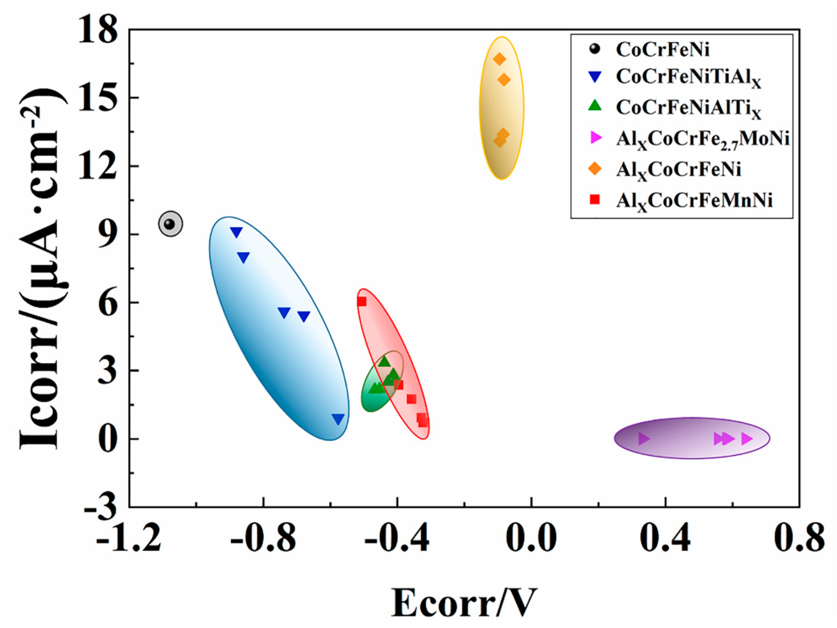
Figure 10 shows the comparison of the self-corrosion potential Ecorr and the self-corrosion current density Icorr of the six HEAs: CoCrFeNiTiAlx, CoCrFeNi, AlxCoCrFeNi, AlxCoCrFeMnNi, CoCrFeNiAiTix, and AlxCoCrFe2.7NiMo [6,12,26,27]. The introduction of Ti element can promote the passivation behavior of the coating due to the formation of TiO2 and Ti2O3 phases. Adding Mo to the CoCrFeNiAl alloy can result in a significant improvement in the corrosion resistance of the alloy, which is ascribed to the fact that Mo can easily produce a dense passivation film. It is generally believed that Al2O3 with a dense structure can effectively resist Cl¯ ion corrosion. While a further increase in Al content leads to an increase in the volume fraction of (Ni,Al)-rich BCC1 phases, which is susceptible to Cl¯ ion corrosion and reduces the local corrosion resistance of the passivation film. Based on this study, the reason for the decrease in corrosion resistance may be attributed to the microstructure evolution. In addition, the changed metal oxide content in the passivation film may play a certain role. Consequently, there should be an interaction between the passivation behavior and the effect of the metal oxide content on the corrosion resistance of HEA alloys and coatings.
4. Conclusion
In this work, the CoCrFeNiTiAlx (x = 0, 0.5, 1, 1.5, 2) coatings were prepared on the surface of AISI1045 steel by laser cladding technology, and its microstructure, hardness, wear resistance, and corrosion resistance were analyzed.
- Under the conditions of high laser power and fast solidification rate, the increase in Al content promoted the transition from a single FCC phase to the BCC1 and BCC2 phases, and a small amount of Laves phase. Due to the larger atomic radius of Al, as the Al element increases, the lattice distortion energy increases, and the BCC2 phase gradually decreases to form a relatively stable BCC1 phase.
- As the Al content increases, the hardness and abrasion resistance of the coating first increase and then decrease. The crystallite size of each phase of the coating also changed, and the grains gradually refined. The grain size difference between the two phases of the Al0.5 coating was the smallest. The grain refinement resulted in the highest hardness of the Al0.5 coating, reaching 880 HV, 6.5 times that of the substrate. The abrasion mechanism was the transition from abrasive wear to slight adhesive wear, and finally to micro-fracture (flake) wear.
- The corrosion resistance of the CoCrFeNiTiAlx HEA coatings in a 3.5% NaCl solution increased first, then decreased with increasing Al content. The addition of a small amount of Al will form an Al2O3 passivation film, the self-corrosion potential of Al0.5 was the most positive, at −0.5766 V, while the self-corrosion current density was the smallest, at 9.13 × 10⁻⁷ A·cm−2. The Al0.5 coating showed good corrosion resistance. This also proves that when there are multiple phases, the performance of the alloy may be better when the crystallite size difference of each phase is small.
- The results show that adding a small amount of aluminum can refine the grains of the CoCrFeNiTiAlx coating and improve the corrosion resistance and mechanical properties of the coating. CoCrFeNiTiAl0.5 exhibits the best performance among the as-prepared coatings, can significantly improve the surface properties of AISI1045 steel.
Author Contributions
General program development and writing, Y.X.; Experiment, Z.L. and J.L.; Experiment guide, F.Z. and L.W.; Compress test, J.H.; Microstructure analysis guide, Y.C.; Theory guide, L.L. All authors have read and agreed to the published version of the manuscript.
Funding
This work was supported in part by the National Key Research and Development Program of China (No. 2016YFB1100103), and it was financially supported by the Program of Study Abroad for Young Scholar sponsored by CSC (China Scholarship Council) (No. 201906565024), the National Natural Science Foundation of China (No. 51301021), the Fundamental Research Funds for the Central Universities (Nos. 300102318205; 310831161020; 310831163401; 300102319304; 300102310108), the Innovation and Entrepreneurship Training Program of Chang’ an University (No. 201910710144), the Key projects of Shaanxi Natural Science Foundation (2019JZ-27), and the Shaanxi Natural Science Basic Research Program-Shaanxi Coal (2019JLM-47).
Conflicts of Interest
The authors declare no conflicts of interest.
References
- Yeh, J.W.; Chen, S.K.; Lin, S.J.; Gan, J.Y.; Chin, T.S.; Shun, T.T.; Tsau, C.H.; Chang, S.Y. Nanostructured high-entropy alloys with multiple principal elements: Novel alloy design concepts and outcomes. Adv. Eng. Mater. 2004, 6, 299–303. [Google Scholar] [CrossRef]
- Zhang, Y.; Zuo, T.T.; Tang, Z.; Gao, M.C.; Dahmen, K.A.; Liaw, P.K.; Lu, Z.P. Microstructures and properties of high-entropy alloys. Prog. Mater. Sci. 2014, 61, 1–93. [Google Scholar] [CrossRef]
- Zhang, Y.; Zhou, Y.J.; Lin, J.P.; Chen, G.L.; Liaw, P.K.; Zhang, Y. Solid-solution phase formation rules for multi-component alloys. Adv. Eng. Mater. 2008, 10, 534–538. [Google Scholar] [CrossRef]
- Li, C.; Li, J.C.; Zhao, M.; Zhao, M.; Jiang, Q. Effect of alloying elements on microstructure and properties of multiprincipal elements high-entropy alloys. J. Alloys Compd. 2009, 475, 752–757. [Google Scholar] [CrossRef]
- Chuang, M.H.; Tsai, M.H.; Wang, W.R.; Lin, S.J.; Yeh, J.W. Microstructure and wear behavior of AlxCo1.5CrFeNi1.5Tiy high-entropy alloys. Acta Mater. 2011, 59, 6308–6317. [Google Scholar] [CrossRef]
- Shang, C.; Axinte, E.; Ge, W.; Zhang, Z.; Wang, Y. High-entropy alloy coatings with excellent mechanical, corrosion resistance and magnetic properties prepared by mechanical alloying and hot pressing sintering. Surf. Interfaces 2017, 9, 36–43. [Google Scholar] [CrossRef]
- Chew, Y.; Bi, G.J.; Zhu, Z.G.; Ng, F.L.; Weng, F.; Liu, S.B.; Nai, S.M.L.; Lee, B.Y. Microstructure and enhanced strength of laser aided additive manufactured CoCrFeNiMn high entropy alloy. Mater. Sci. Eng. A 2019, 744, 137–144. [Google Scholar] [CrossRef]
- Liu, G.; Liu, L.; Liu, X.; Wang, Z.; Han, Z.; Zhang, G.; Kostka, A. Microstructure and mechanical properties of Al0.7CoCrFeNi high-entropy-alloy prepared by directional solidification. Intermetallics 2018, 93, 93–100. [Google Scholar] [CrossRef]
- Hong, S.; Wu, Y.; Li, G.; Wang, B.; Gao, W.; Ying, G. Microstructural characteristics of high-velocity oxygen-fuel (HVOF) sprayed nickel-based alloy coating. J. Alloys Compd. 2013, 581, 398–403. [Google Scholar] [CrossRef]
- Wang, C.; Yu, J.; Zhang, Y.; Yu, Y. Phase evolution and solidification cracking sensibility in laser remelting treatment of the plasma-sprayed CrMnFeCoNi high entropy alloy coating. Mater. Des. 2019, 182, 108040. [Google Scholar] [CrossRef]
- Anupam, A.; Kottada, R.S.; Kashyap, S.; Meghwal, A.; Murty, B.; Berndt, C.; Ang, A. Understanding the microstructural evolution of high entropy alloy coatings manufactured by atmospheric plasma spray processing. Appl. Surf. Sci. 2019, 505, 144117. [Google Scholar] [CrossRef]
- Liu, J.; Liu, H.; Chen, P.; Hao, J. Microstructural characterization and corrosion behaviour of AlCoCrFeNiTix high-entropy alloy coatings fabricated by laser cladding. Surf. Coat. Technol. 2019, 361, 63–74. [Google Scholar] [CrossRef]
- Zhang, S.; Wu, C.L.; Zhang, C.H.; Guan, M.; Tan, J.Z. Laser surface alloying of FeCoCrAlNi high-entropy alloy on 304 stainless steel to enhance corrosion and cavitation erosion resistance. Opt. Laser Technol. 2016, 84, 23–31. [Google Scholar] [CrossRef]
- Matilainen, V.; Piili, H.; Salminen, A.; Syvänen, T.; Nyrhilä, O. Characterization of process efficiency improvement in laser additive manufacturing. Phys. Procedia 2014, 56, 317–326. [Google Scholar] [CrossRef] [Green Version]
- Ocelík, V.; Janssen, N.; Smith, S.N.; De Hosson, J.T.M. Additive Manufacturing of High-Entropy Alloys by Laser Processing. JOM 2016, 68, 1810–1818. [Google Scholar] [CrossRef] [Green Version]
- Liu, Y.Y.; Chen, Z.; Chen, Y.Z.; Shi, J.C.; Wang, Z.Y.; Wang, S.; Liu, F. Effect of Al content on high temperature oxidation resistance of AlxCoCrCuFeNi high entropy alloys (x = 0, 0.5, 1, 1.5, 2). Vacuum 2019, 169, 108837. [Google Scholar] [CrossRef]
- Zhang, K.; Fu, Z. Effects of annealing treatment on phase composition and microstructure of CoCrFeNiTiAlx high-entropy alloys. Intermetallics 2012, 22, 24–32. [Google Scholar] [CrossRef]
- Liu, Y.Y.; Chen, Z.; Chen, Y.; Shi, J.; Wang, Z.; Zhang, J. The effect of Al content on microstructures and comprehensive properties in AlxCoCrCuFeNi high entropy alloys. Vacuum 2019, 161, 143–149. [Google Scholar] [CrossRef]
- Jiang, S.; Lin, Z.; Xu, H.; Sun, Y. Studies on the microstructure and properties of AlxCoCrFeNiTi1−x high entropy alloys. J. Alloys Compd. 2018, 741, 826–833. [Google Scholar] [CrossRef]
- Kao, Y.F.; Lee, T.D.; Chen, S.K.; Chang, Y.S. Electrochemical passive properties of AlxCoCrFeNi (x = 0, 0.25, 0.50, 1.00) alloys in sulfuric acids. Corros. Sci. 2010, 52, 1026–1034. [Google Scholar] [CrossRef]
- Guo, S.; Liu, C.T. Phase stability in high entropy alloys: Formation of solid-solution phase or amorphous phase. Prog. Nat. Sci. Mater. Int. 2011, 21, 433–446. [Google Scholar] [CrossRef] [Green Version]
- Archard, J.F. Contact and Rubbing of Flat Surfaces. J. Appl. Phys. 1953, 24, 981–988. [Google Scholar] [CrossRef]
- Zhou, Y.J.; Zhang, Y.; Wang, F.J.; Chen, G.L. Phase transformation induced by lattice distortion in multiprincipal component CoCrFeNiCuXAl1−x solid-solution alloys. Appl. Physics. Lett. 2008, 92, 121–123. [Google Scholar] [CrossRef]
- Courtney, T. Mechanical Behavior of Materials; McGraw-Hill: New York, NY, USA, 1990; p. 173. [Google Scholar]
- Tong, C.J.; Chen, M.R.; Yeh, J.W.; Lin, S.J.; Chen, S.K.; Shun, T.T.; Chang, S.Y. Mechanical performance of the AlxCoCrCuFeNi high-entropy alloy system with multiprincipal elements. Metall. Mater. Trans. A 2005, 36, 1263–1271. [Google Scholar] [CrossRef]
- Sha, M.; Jia, C.; Qiao, J.; Feng, W.; Ai, X.; Jing, Y.-A.; Shen, M.; Li, S. Microstructure and Properties of High-Entropy AlxCoCrFe2.7MoNi Alloy Coatings Prepared by Laser Cladding. Metals 2019, 9, 1243. [Google Scholar] [CrossRef] [Green Version]
- Ye, F.; Jiao, Z.; Yan, S.; Guo, L.; Feng, L.; Yu, J. Microbeam plasma arc remanufacturing: Effects of Al on microstructure, wear resistance, corrosion resistance and high temperature oxidation resistance of AlxCoCrFeMnNi high-entropy alloy cladding layer. Vacuum 2020, 174, 109178. [Google Scholar] [CrossRef]
Figure 1.
Schematic diagram of the laser cladding.

Figure 2.
XRD diffraction patterns of the CoCrFeNiTiAlx (x = 0, 0.5, 1.0, 1.5, 2.0) coatings.
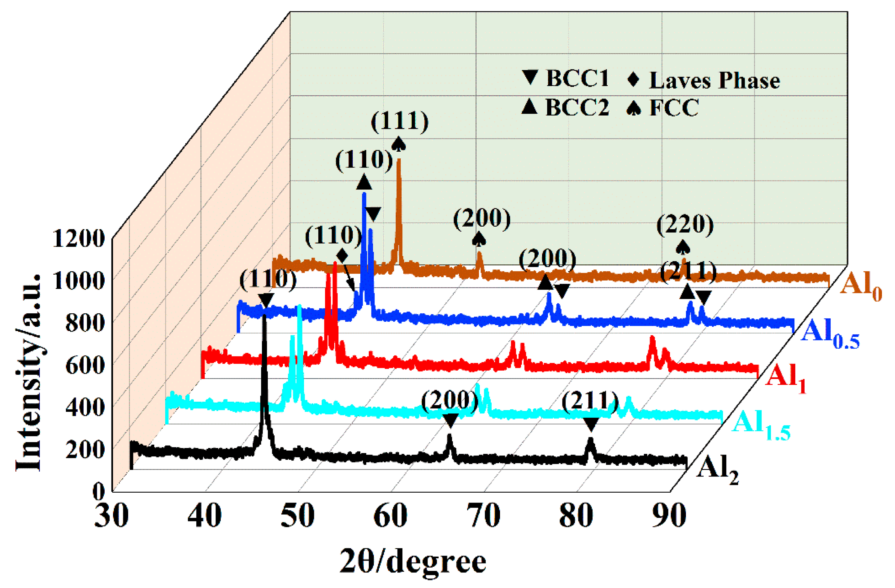
Figure 3.
Scanning electron microscopy (SEM) micrographs of the CoCrFeNiTiAlx high-entropy alloy coatings: (a) Al0 coating; (b) Al0.5 coating; (c) Al1 coating; (d) Al1.5 coating; and (e) Al2 coating. DR, dendritic region; ID, interdendritic region.
Figure 3.
Scanning electron microscopy (SEM) micrographs of the CoCrFeNiTiAlx high-entropy alloy coatings: (a) Al0 coating; (b) Al0.5 coating; (c) Al1 coating; (d) Al1.5 coating; and (e) Al2 coating. DR, dendritic region; ID, interdendritic region.

Figure 4.
SEM of Al0.5 high-entropy alloy coating: (a) cross-sectional morphology and selected area line scan of Al0.5 high-entropy alloy coating and (b) elemental distribution maps of Al0.5 high-entropy alloy coating. HAZ, heat-affected zone; HEAC, high-entropy alloy coating.
Figure 4.
SEM of Al0.5 high-entropy alloy coating: (a) cross-sectional morphology and selected area line scan of Al0.5 high-entropy alloy coating and (b) elemental distribution maps of Al0.5 high-entropy alloy coating. HAZ, heat-affected zone; HEAC, high-entropy alloy coating.

Figure 5.
The microhardness distribution curve of the CoCrFeNiTiAlx high-entropy alloy coatings.
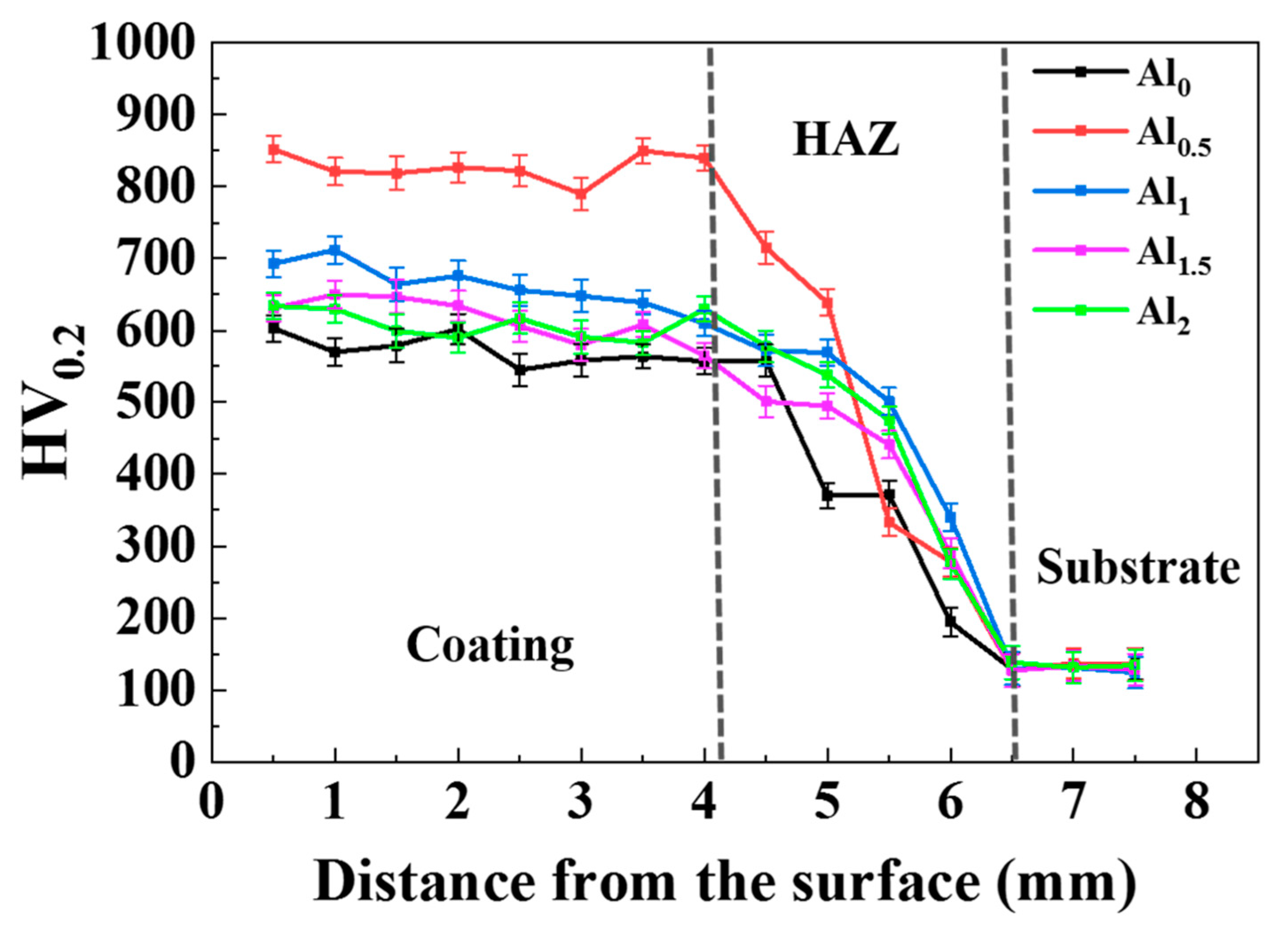
Figure 6.
(a) variation of the friction coefficients versus test time for the CoCrFeNiTiAlx high-entropy alloy coatings and substrate; (b) SEM patterns after wearing of the CoCrFeNiTiAlx high-entropy alloy coatings and substrate; and (c) sass loss of the CoCrFeNiTiAlx high-entropy alloy coatings and substrate.
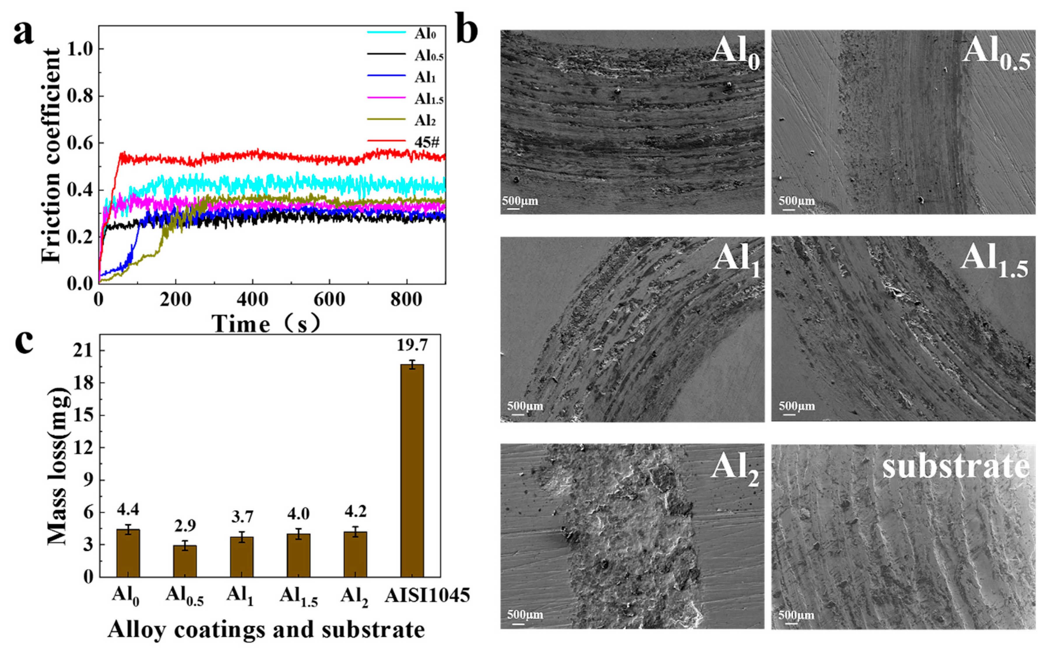
Figure 7.
Tafel polarization curves of the CoCrFeNiTiAlx high-entropy alloy coatings and the AISI1045 steel.
Figure 7.
Tafel polarization curves of the CoCrFeNiTiAlx high-entropy alloy coatings and the AISI1045 steel.

Figure 8.
The transmission electron microscope (TEM) images of the Al0.5 coating: (a) TEM bright-field micrographs; (b) High resolution transmission electron microscope (HRTEM) image and Selected area electron diffraction (SAED) of the marked BCC1 and BCC2 phase boundary area in (a); (c) TEM bright-field magnified micrographs; (d) energy dispersive spectrometer (EDS) element mapping of TEM bright imaging in (a); and (e) selected area line scan image shown by an arrow in (c).
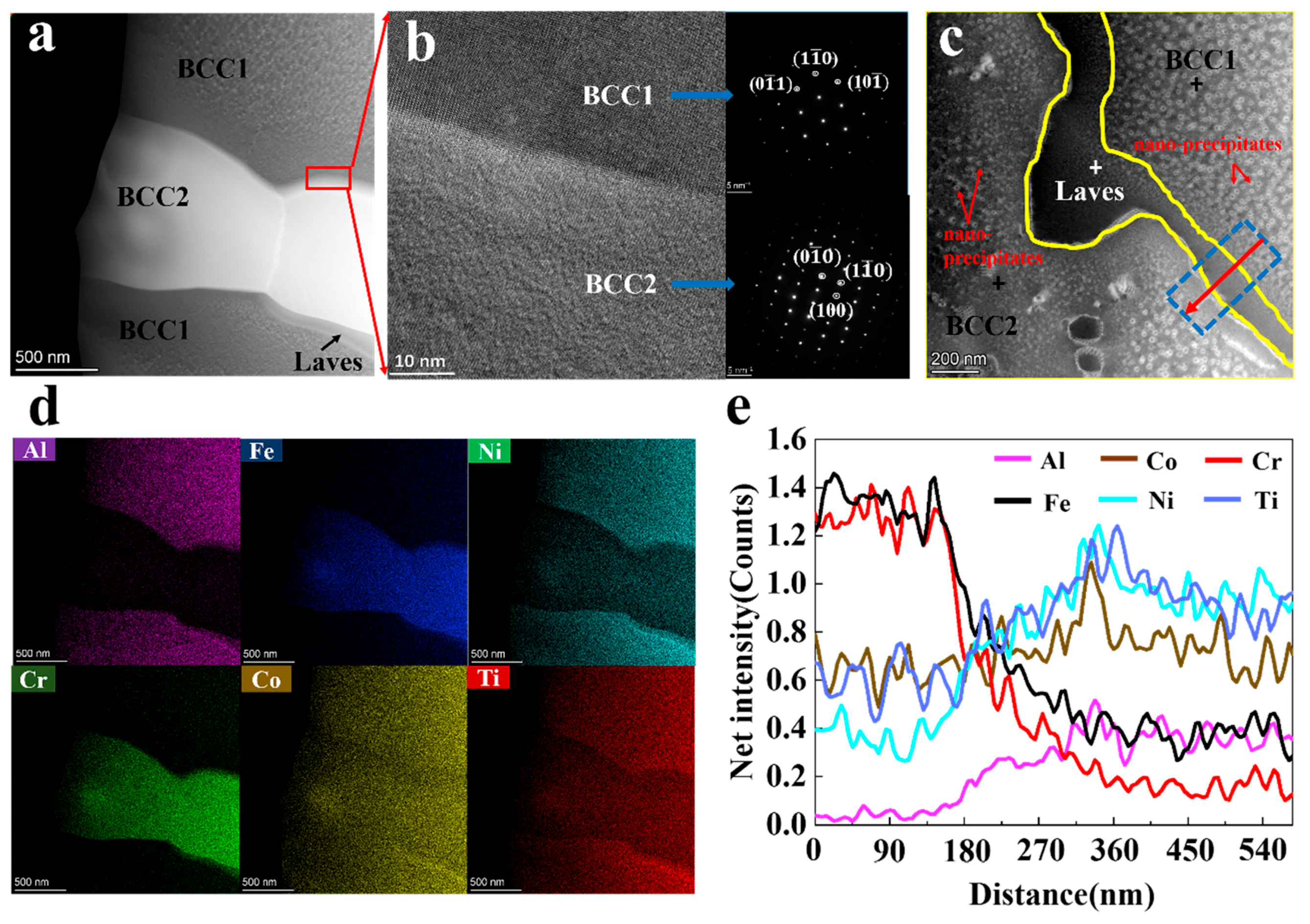
Figure 9.
Relationship between the volume fraction of the phases and the average microhardness of the coatings.
Figure 9.
Relationship between the volume fraction of the phases and the average microhardness of the coatings.
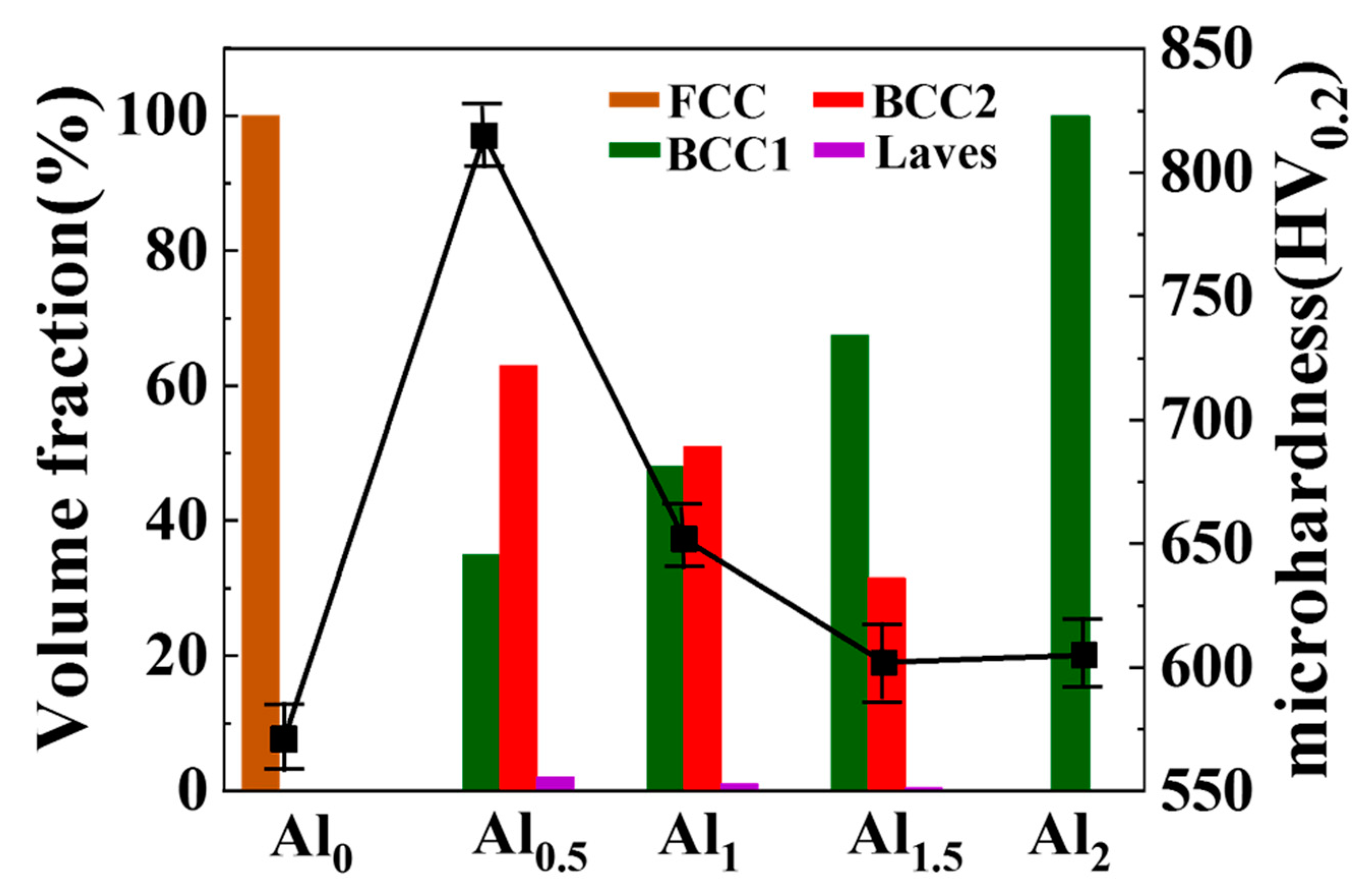
Figure 10.
Comparison of the corrosion resistance of CoCrFeNi, AlxCoCrFeNi, CoCrFeNiAlTix, AlxCoCrFeMnNi, AlxCoCrFe2.7MoNi, and CoCrFeNiTiAlx HEAs in a 3.5 wt.% NaCl solution.
Figure 10.
Comparison of the corrosion resistance of CoCrFeNi, AlxCoCrFeNi, CoCrFeNiAlTix, AlxCoCrFeMnNi, AlxCoCrFe2.7MoNi, and CoCrFeNiTiAlx HEAs in a 3.5 wt.% NaCl solution.

Table 1.
The mass of elements of CoCrFeNiTiAlx high entropy alloy coatings (g).
| Element | Co | Cr | Fe | Ni | Ti | Al |
|---|---|---|---|---|---|---|
| CoCrFeNiTi | 23.56 | 20.80 | 22.40 | 23.48 | 19.16 | 0 |
| CoCrFeNiTiAl0.5 | 23.56 | 20.80 | 22.40 | 23.48 | 19.16 | 5.40 |
| CoCrFeNiTiAl1 | 23.56 | 20.80 | 22.40 | 23.48 | 19.16 | 10.80 |
| CoCrFeNiTiAl1.5 | 23.56 | 20.80 | 22.40 | 23.48 | 19.16 | 16.20 |
| CoCrFeNiTiAl2 | 23.56 | 20.80 | 22.40 | 23.48 | 19.16 | 21.60 |
Table 2.
Process parameters of laser cladding.
| Parameters | Data |
|---|---|
| Laser power | 2100 W |
| Scan speed | 9 mm/s |
| Laser beam diameter | 5 mm |
| Single layer thickness | 0.2 mm |
| Layers | 30 |
| Mass of feed powder | 8 g/min |
| Cladding area | 60 × 30 mm2 |
| Element | Co | Cr | Fe | Ni | Ti | Al |
|---|---|---|---|---|---|---|
| Co | - | −4 | −1 | 0 | −28 | −19 |
| Cr | −4 | - | −1 | −7 | −1 | −10 |
| Fe | −1 | −1 | - | −2 | −17 | −11 |
| Ni | 0 | −7 | −2 | - | −35 | −22 |
| Ti | −28 | −1 | −17 | −35 | - | −30 |
| Al | −19 | −10 | −11 | −22 | −30 | - |
Table 4.
Corrosion dynamics parameters for the CoCrFeNiTiAlx HEA coatings and the AISI1045 steel.
| Sample No. | ba (mV) | bc (mV) | Ecorr/V | Icorr/(A·cm−2) |
|---|---|---|---|---|
| Al0 | 227.05 | 149.37 | −0.7382 | 5.60 × 10⁻⁶ |
| Al0.5 | 140.14 | 78.60 | −0.5766 | 9.13 × 10⁻⁷ |
| Al1 | 90.25 | 102.11 | −0.6791 | 5.43 × 10⁻⁶ |
| Al1.5 | 157.32 | 146.30 | −0.8591 | 8.03 × 10⁻⁶ |
| Al2 | 48.80 | 58.86 | −0.8802 | 9.14 × 10⁻⁶ |
| AISI1045 | 40.97 | 46.244 | −0.9701 | 4.71 × 10⁻⁵ |
Table 5.
EDS composition of different points corresponding to the three cross marks in Figure 8c.
Table 5.
EDS composition of different points corresponding to the three cross marks in Figure 8c.
| Element | Co | Cr | Fe | Ni | Ti | Al |
|---|---|---|---|---|---|---|
| BCC1 | 20.58 | 3.99 | 9.55 | 25.14 | 25.58 | 15.16 |
| BCC2 | 15.79 | 28.05 | 29.94 | 10.04 | 14.47 | 1.71 |
| Laves | 18.02 | 12.80 | 17.25 | 20.24 | 22.01 | 9.69 |
© 2020 by the authors. Licensee MDPI, Basel, Switzerland. This article is an open access article distributed under the terms and conditions of the Creative Commons Attribution (CC BY) license (http://creativecommons.org/licenses/by/4.0/).
Share and Cite
MDPI and ACS Style
Xu, Y.; Li, Z.; Liu, J.; Chen, Y.; Zhang, F.; Wu, L.; Hao, J.; Liu, L. Microstructure Evolution and Properties of Laser Cladding CoCrFeNiTiAlx High-Entropy Alloy Coatings. Coatings 2020, 10, 373. https://doi.org/10.3390/coatings10040373
AMA Style
Xu Y, Li Z, Liu J, Chen Y, Zhang F, Wu L, Hao J, Liu L. Microstructure Evolution and Properties of Laser Cladding CoCrFeNiTiAlx High-Entropy Alloy Coatings. Coatings. 2020; 10(4):373. https://doi.org/10.3390/coatings10040373
Chicago/Turabian StyleXu, Yiku, Zhiyuan Li, Jianru Liu, Yongnan Chen, Fengying Zhang, Lei Wu, Jianmin Hao, and Lin Liu. 2020. "Microstructure Evolution and Properties of Laser Cladding CoCrFeNiTiAlx High-Entropy Alloy Coatings" Coatings 10, no. 4: 373. https://doi.org/10.3390/coatings10040373
Note that from the first issue of 2016, this journal uses article numbers instead of page numbers. See further details here.