Deposition Mechanism and Thickness Control of CVD SiC Coatings on NextelTM440 Fibers


1
Unit 96901 of People’s Liberation Army, Beijing 100094, China
2
Science and Technology on Advanced Ceramic Fibers and Composites Laboratory, National University of Defense Technology, Changsha 410073, China
*
Author to whom correspondence should be addressed.
Coatings 2020, 10(4), 408; https://doi.org/10.3390/coatings10040408
Submission received: 17 February 2020
/
Revised: 14 April 2020
/
Accepted: 15 April 2020
/
Published: 20 April 2020
(This article belongs to the Special Issue Functional Ceramic Coatings)
Abstract
:SiC coatings were successfully synthesized on NextelTM440 fibers by chemical vapor deposition (CVD) using methyltrichlorosilane as the original SiC source at 1373 K. After deposited, the fibers were fully surrounded by uniform coatings with some bulges. The X-ray diffraction (XRD), X-ray photoelectron spectroscopy (XPS) and high-resolution transmission electron microscopy (HR-TEM) results indicated that the coatings were composed of β-SiC and free carbon. Moreover, thickness control of the coatings could be carried out by adjusting the deposition time. The coating thickness rose exponentially, and the exterior of the coatings became looser as the deposition time increased. The thickness of about 1.5 µm was obtained after depositing for 4 h. The coating thickness was also theoretically calculated, and the result agreed well with the measured thickness. Finally, the related deposition mechanism is discussed and a deposition model is built.
1. Introduction
SiC ceramic has attracted extensive attention due to its excellent performance, such as appropriate high-temperature strength, relatively high oxidation, corrosion and thermal-shock resistance [1,2,3,4], etc. SiC ceramic can be used in coating materials, especially in fiber-reinforced ceramic matrix composites (FRCMCs) to improve the bond strength between the fiber and matrix. After introducing SiC interphases, weak fiber/matrix interfaces can be obtained in FRCMCs and several toughening mechanisms like crack deflection, fiber debonding, bridging and subsequent pullout can occur, all of which contribute to damage tolerance [5,6,7]. Our previous works proved that SiC interphases were suitable for the strength improvement of high-temperature structural and functional materials due to its oxidation tolerance and relatively temperature-stable dielectric characteristics [8,9].
SiC coatings have been successfully deposited by CVD on silicon carbide fibers, carbon fibers, oxide fibers and more [10,11,12]. Most research has focused on the coatings’ effects on microstructure and mechanical properties of those fibers, the strength improvement of the fiber-reinforced ceramic matrix composites, or the degradation mechanism of the coatings [13,14]. However, research on the deposition mechanism and thickness control of CVD SiC coatings on oxide fibers is rare.
In the present study, SiC coatings were synthesized on NextelTM440 fibers by CVD using the gas system of CH3SiCl3–H2–Ar. The coating thickness was adjusted by varying the deposition time, and the deposition mechanism was investigated by the aid of microstructure and composition analysis.
2. Experimental Procedure
2.1. Materials and Deposition of Coatings
NextelTM440 fiber fabrics (BF-30, 3M, St. Paul, MN, USA) were employed as the sample for deposited coating. The fiber, with a diameter of about 11 μm, was composed of Al2O3 (70 wt.%), SiO2 (28 wt.%) and B2O3 (2 wt.%) [15]. Methyltrichlorosilane (MTS, CH3SiCl3) was used as the SiC precursor, with hydrogen as carrier gas and argon as diluent and protective gas, respectively. As shown in Figure 1, the deposition process of SiC coating was carried out in a hot-wall vertical reactor. Prior to the deposition, the fiber fabrics were desized, ultrasonically cleaned in acetone and dried in an oven. The deposition was performed at 1373 K under a total pressure of 5.0 kPa, with hydrogen and argon flow rates of 200 and 75 sccm, respectively. The coatings were deposited for 1, 2 and 4 h, respectively.
2.2. Characterization
The microstructure of the fibers without and with coatings was characterized by scanning electron microscope (SEM) equipped with energy dispersed spectroscopy (EDS) (HITACHI FEG S4800, HITACHI, Tokyo, Japan). The phase composition of the fibers without and with coatings was analyzed by XRD equipped with a D8 ADVANCE diffractometer using monochromatic Cu Kα radiation (Bruker, Hamburg, Germany). The chemical composition of the fibers without and with coatings was traced by XPS using Al Kα radiation of energy 1486.6 eV (Thermo ESCALAB 250, Thermo Scientific, Waltham, MA, USA). TEM analysis was carried out on Tecnai F20 operating at 200 kV, and the samples were prepared according to [16].
3. Results and Discussion
3.1. Characteristics of the CVD SiC Coatings
The surface of the fibers without and with SiC coatings was observed by SEM. As shown in Figure 2, the as-received fibers showed a smooth and homogeneous surface, except for a few white sheet alumina micro-grains. After depositing for 2 h with SiC coatings, the fiber surface was no longer smooth and a large number of micro-bulges with the largest diameter of about 1 µm appeared. The coatings were generally dense, without any micro-cracks or pores.
The phase composition of the fibers without and with SiC coatings was analyzed by XRD. As shown in Figure 3a, diffraction peaks of mullite and γ-Al2O3 were detected for the as-received fibers. After being coated with SiC coatings (Figure 3b), three accessional peaks (2θ = 35.60°, 60.06° and 71.83°) were observed, which respectively belonged to the (111), (220) and (311) crystal planes of β-SiC. It is clear that the coatings were mainly composed of β-SiC phase [17].
The chemical composition of the fibers without and with SiC coatings was analyzed by XPS. As shown in the survey scan (Figure 4a), the peaks of Al 2s and Al 2p disappeared after depositing with SiC coatings. Element analysis of the coated fibers revealed that the content of C increased while the contents of Al, Si and O decreased greatly. Moreover, the Cl 2p3/2 (~198 eV) peak and Cl 2s (~271 eV) peak were detected [18], indicating the absorption of HCl. As shown in Figure 4b, the C 1s peak could be fitted into two sub peaks, C–Si bond (282.6 eV) and C–C bond (283.2 eV) [19], which was attributed to SiC and carbon, respectively. As shown in Figure 4c, the Si 2p peak positioned at 100.9 eV was also attributed to Si–C bonding. In conclusion, the coatings were composed of β-SiC and free carbon.
An HR-TEM image of SiC coatings deposited for 2 h on the fibers is displayed in Figure 5a. It could be found that the coatings consisted of large quantities of turbostratic carbon and some cubic β-SiC micro-grains oriented in the (111) crystal plane with 0.250 nm spacing. The result was coincident with XPS analysis and revealed that the coatings were rich in carbon. As shown in the SAED pattern (Figure 5b), the diffraction rings could be indexed as (111), (220) and (311) planes of cubic β-SiC [20].
3.2. Thickness Control of the CVD SiC Coatings
The cross-sectional morphology of the samples deposited for different amounts of time is shown in Figure 6. It is apparent that the fibers were surrounded closely by SiC coatings. The coating thickness was measured 10 times at different points to obtain the average value. As shown in Table 1, the coating thickness increased with the deposition time, and the value of about 1.5 µm was obtained after depositing for 4 h. Figure 7 shows the effect of the deposition time on the coating thickness. It could be found that the thickness of the coatings deposited for 1, 2 and 4 h increased exponentially with the deposition time. However, the exterior of the coatings became looser as the deposition time increased above 2 h, owing to the reduction of the adhesion force on the coating surface, thus leading to the deposition difficulty of new raw materials [21,22].
In this study, the coating thickness (d) was also calculated according to the corresponding relationship between volume and weight for the coatings and fibers, which was summarized by Y. Zheng et al. [23]:
where r0 is the original fiber radius; c = (ρf/ρc), where ρc and ρf are the density of the coatings and fibers, respectively; and η = (ωc/ωf)%, where ωc and ωf are the weight of the coatings and fibers.
The original fiber radius (r0) was about 10 μm. The density of the pure SiC was 3.20 g/cm3. As the coatings were rich in carbon, the coating density (ρc) was not constant, and should be calculated according to the volume mixing law, where the volume ratio of the carbon and SiC in the coatings can be obtained by element ratio from XPS analysis. Then, the parameter ρc can be expressed as:
Combining Equations (1) and (2), and adopting ρf = 3.0 g/cm3, the coating thickness could be obtained and the results are shown in Table 1:
As shown in Figure 7, both the measured and calculated coating thickness increased exponentially with the deposition time. The results of both methods were quite consistent in general. The calculated thickness was a little larger than the measured one. There were two main reasons: one was that the volume ratio of the carbon in the coatings was not accurate due to the ladder-like decrease of the carbon with the deposition time; the other one was that the coatings were a little loose. As a result, the actual coating density was different from the theoretical one. However, the calculated thickness could still reflect the actual one, and it was meaningful for the thickness control of CVD coatings.
3.3. Deposition Mechanism Research
The chemical reaction process of CVD SiC coatings using MTS as a raw material was investigated to explain the deposition mechanism for the coatings. As the bond energy for C–Si, C–H and Si–Cl are 314, 337 and 466 J/mol, respectively, the breakdown of the C–Si bond occurred first at high temperature. The reaction process can be summarized as follows [24,25]:
where < Si > and < C > correspond to the intermediate states of Si and C, which can form SiC as shown in Equation (7). It can be concluded from Equations (5)–(7) that hydrogen has a great effect on the formation of silicon or free carbon during the CVD process. That is to say, pure SiC coatings can hardly be prepared via CVD process, and they will always be rich in silicon or free carbon. It is reported in the literature that coatings deposited on carbon plate, fibers or composites by CVD using MTS at temperatures above 1200 °C are usually composed of SiC, and Si impurities form at lower deposition temperature [25,26,27]. In this study, the coatings deposited on NextelTM440 fibers by CVD using MTS at 1100 °C were composed of SiC and free carbon.
In addition, the cross-sectional morphology of the coated fibers (Figure 6a–c) revealed that the coatings were loose. In order to investigate structure and composition of the interior of the coatings, the fibers with SiC coatings deposited for 2 h were ultrasonically treated to thin the coatings from 364.2 to 97.6 nm. As shown in Figure 8a,b, many hemispherical bulges with uniform diameter of about 4 μm with a disorderly distribution on the fiber surface. The magnified SEM image (Figure 8c) shows that the plane area of the coatings was dense and smooth, without any defects. Furthermore, the EDS analysis (Figure 8e–f) revealed that after ultrasonic treatment, the fibers were totally covered by thin carbon layers with few SiC bulges. Compared to the original coatings (Figure 4b), no Cl peak was detected, indicating a dense structure for the interior of the coatings, without any absorption of HCl.
As a result, the deposition mechanism can be described. As shown in Figure 2b and schematized in Figure 9a, there were a few white sheet alumina micro-grains with disorderly distribution on the original fibers. Theses micro-grains not only increased the specific surface area but also had high catalysis activity, which led to the < Si > and < C > attaching onto them and reacting to form spherical SiC particles rapidly. At the same time, MTS was decompounding and depositing on fibers per Equations (4)–(9) to form carbon-rich SiC coatings (as shown in Figure 9b). As the deposition process continued and the coating thickness increased, the growth rate of spherical SiC particles and deposition rate of SiC coatings gradually became close to each other, and a relatively smooth surface was finally obtained (Figure 9c). As mentioned previously, SiC coatings became looser as the coating thickness increased due to the reduction of adhesion force on the coating surface.
4. Conclusions
We investigated the deposition mechanism of CVD SiC coatings on NextelTM440 fibers, and thickness control of the coatings was actualized by varying the deposition time. The main conclusions can be summarized as follows:
- Carbon-rich SiC coatings were synthesized on NextelTM440 fibers by CVD. Some traces of bulges were observed on the coating surface.
- CVD SiC coatings with different thickness were obtained by varying the deposition time. As the deposition time increased from 1 to 4 h, the coating thickness increased from 143.5 nm to 1.5 µm accordingly. An empirical formula was put forward to calculate the coating thickness, and the calculated thickness was quite coincident with the measured one.
- The deposition mechanism of the coatings was discussed. Spherical SiC particles were formed at a high rate on alumina micro-grains at the fiber surface, and the coatings became looser with increasing thickness due to the reduction of the adhesion force on the coating surface.
Coatings composed of β-SiC and free carbon could be used for interface engineering of oxide fiber-reinforced composites. After preparation of the composites under inert atmosphere, free carbon could be oxidized to obtain porous SiC interphases, which could improve the fiber/matrix interface characteristics. Further work will focus on interface engineering of NextelTM440-reinforced mullite composite by porous SiC interphases. The damage mode and strength of the composites will be systematically investigated.
Author Contributions
Conceptualization, Y.W. and H.C.; Data curation, J.S. and B.S.; Investigation, Y.W., J.S. and H.C.; Methodology, Y.W. and B.S.; Writing—original draft, Y.W.; Writing—review and editing, H.C. All authors have read and agreed to the published version of the manuscript.
Funding
This research was funded by the National Natural Science Foundation of China (NSFC) under Grant No. 51602347.
Conflicts of Interest
The authors declare no conflicts of interest.
References
- Naslain, R. Design, preparation and properties of non-oxide CMCs for application in engines and nuclear reactors: An overview. Compos. Sci. Technol. 2004, 64, 155–170. [Google Scholar] [CrossRef]
- Koyanagi, T.; Katoh, Y.; Nozawa, T.; Snead, L.-L.; Kondo, S.; Henager, C.-H., Jr.; Ferraris, M.; Hinoki, T.; Huang, Q. Recent progress in the development of SiC composites for nuclear fusion applications. J. Nucl. Mater. 2018, 511, 544–555. [Google Scholar] [CrossRef]
- Arai, Y.; Inoue, R.; Goto, K.; Kogo, Y. Carbon fiber reinforced ultra-high temperature ceramic matrix composites: A review. Ceram. Int. 2019, 45, 14481–14489. [Google Scholar] [CrossRef]
- Shen, Z.-Z.; Chen, J.-H.; Li, B.; Li, G.-Q.; Zhang, Z.-J.; Hou, X.-M. Recent progress in SiC nanowires as electromagnetic microwaves absorbing materials. J. Alloy. Comp. 2020, 815, 152388. [Google Scholar] [CrossRef]
- Chawla, K.-K. Interface engineering in mullite fiber/mullite matrix composites. J. Eur. Ceram. Soc. 2008, 28, 447–453. [Google Scholar] [CrossRef]
- Zhang, M.-Y.; Li, K.-Z.; Shi, X.-H.; Tan, W.-L. Effects of SiC interphase on the mechanical and ablation properties of C/C-ZrC-ZrB2-SiC composites prepared by precursor infiltration and pyrolysis. Mater. Des. 2017, 122, 322–329. [Google Scholar] [CrossRef]
- Zhou, W.; Long, L.; Li, Y. Mechanical and electromagnetic wave absorption properties of Cf-Si3N4 ceramics with PyC/SiC interphases. J. Mater. Sci. Technol. 2019, 35, 2809–2813. [Google Scholar] [CrossRef]
- Tian, H.; Liu, H.-T.; Cheng, H.-F. A high-temperature radar absorbing structure: Design, fabrication, and characterization. Compos. Sci. Technol. 2014, 90, 202–208. [Google Scholar] [CrossRef]
- Wang, Y.; Cheng, H.-F.; Wang, J. Mechanical and Dielectric Properties of Mullite Fiber-Reinforced Mullite Matrix Composites with Single Layer CVD SiC Interphases. Int. J. Appl. Ceram. Technol. 2015, 12, 500–509. [Google Scholar] [CrossRef]
- Liu, H.-T.; Cheng, H.-F.; Wang, J.; Tang, G.-P. Effects of the single layer CVD SiC interphases on the mechanical properties of the SiCf/SiC composites fabricated by PIP process. Ceram. Int. 2010, 36, 2033–2037. [Google Scholar] [CrossRef]
- Xiang, Y.; Li, W.; Wang, S.; Chen, Z.-H. Effects of the single layer CVD SiC interphases on the mechanical properties of the C/SiC composites fabricated by PIP process. Mater. Sci. Eng. A 2012, 558, 451–455. [Google Scholar]
- Wang, Y.; Cheng, H.-F.; Wang, J. Effects of the single layer CVD SiC interphases on mechanical properties of mullite fiber-reinforced mullite matrix composites fabricated via a sol–gel process. Ceram. Int. 2014, 40, 4707–4715. [Google Scholar] [CrossRef]
- Yu, H.-J.; Zhou, X.-G.; Zhang, W.; Peng, H.-X.; Zhang, C.-R. Mechanical behavior of SiCf/SiC composites with alternating PyC/SiC multilayer interphases. Mater. Des. 2013, 44, 320–324. [Google Scholar] [CrossRef]
- Chen, S.-A.; Zhang, Y.-D.; Zhang, C.-R.; Zhao, D.; Hu, H.-F.; Zhang, Z.-B. Effects of SiC interphase by chemical vapor deposition on the properties of C/ZrC composite prepared via precursor infiltration and pyrolysis route. Mater. Des. 2013, 46, 497–502. [Google Scholar] [CrossRef]
- 3MTM NextelTM Ceramic Fibers and Textiles Technical Reference Guide. 2018. Available online: http://www.3M.com/ceramics (accessed on 9 February 2019).
- Hay, R.-S.; Welch, J.-R.; Cinibulk, M.-K. TEM specimen preparation and characterization of ceramic coatings on fiber tows. Thin Solid Films 1997, 308–309, 389–392. [Google Scholar] [CrossRef]
- Youm, M.-R.; Yun, S.; Choi, S.-C.; Park, S.-W. Synthesis of β-SiC powders by the carbothermal reduction of porous SiO2–C hybrid precursors with controlled surface area. Ceram. Int. 2020, 46, 4870–4877. [Google Scholar] [CrossRef]
- Jiamprasertboon, A.; Dixon, S.-C.; Sathasivam, S.; Powell, M.-J.; Lu, Y.; Siritanon, T.; Carmalt, C.-J. Low-Cost One-Step Fabrication of Highly Conductive ZnO:Cl Transparent Thin Films with Tunable Photocatalytic Properties via Aerosol-Assisted Chemical Vapor Deposition. ACS Appl. Electron. Mater. 2019, 1, 1408–1417. [Google Scholar] [CrossRef] [Green Version]
- Zhang, C.; Qu, L.; Yuan, W.-J. Effects of Si/C ratio on the phase composition of Si-C-N powders synthesized by carbonitriding. Materials 2020, 13, 346. [Google Scholar] [CrossRef] [Green Version]
- Dietrich, D.; Martin, P.-W.; Nestler, K.; Stöckel, S.; Weise, K.; Marx, G. Transmission electron microscopic investigations on SiC- and BN-coated carbon fibres. J. Mater. Sci. 1996, 31, 5979–5984. [Google Scholar] [CrossRef]
- Górka, J.; Czupryński, A.; Żuk, M. Properties and structure of deposited nanocrystalline coatings in relation to selected construction materials resistant to abrasive wear. Materials 2018, 11, 1184. [Google Scholar] [CrossRef] [Green Version]
- Czupryński, A. Flame spraying of aluminum coatings reinforced with particles of carbonaceous materials as an alternative for laser cladding technologies. Materials 2019, 12, 3467. [Google Scholar] [CrossRef] [PubMed] [Green Version]
- Zheng, Y.; Wang, S.-B. Synthesis of boron nitride coatings on quartz fibers: Thickness control and mechanism research. Appl. Surf. Sci. 2011, 257, 10752–10757. [Google Scholar] [CrossRef]
- Reznik, B.; Gerthsen, D.; Zhang, W.-G.; Hüttinger, K.-J. Microstructure of SiC deposited from methyltrichlorosilane. J. Eur. Ceram. Soc. 2003, 23, 1499–1508. [Google Scholar] [CrossRef]
- Zhang, W.-G.; Hüttinger, K.-J. CVD of SiC from Methyltrichlorosilane. Part II: Composition of the Gas Phase and the Deposit. Chem. Vap. Depos. 2001, 7, 173–181. [Google Scholar] [CrossRef]
- Long, Y.; Javed, A.; Chen, Z.-K.; Xiong, X.; Xiao, P. Deposition rate, texture, and mechanical properties of SiC coatings produced by chemical vapor deposition at different temperatures. Int. J. Appl. Ceram. Technol. 2013, 10, 11–19. [Google Scholar] [CrossRef]
- Zhou, W.; Long, Y. Mechanical properties of CVD-SiC coatings with Si impurity. Ceram. Int. 2018, 44, 21730–21733. [Google Scholar] [CrossRef]
Figure 1.
Deposition process of SiC coatings on NextelTM440 fibers.

Figure 2.
Surface morphology of the fibers without (a) and with (b) coatings.
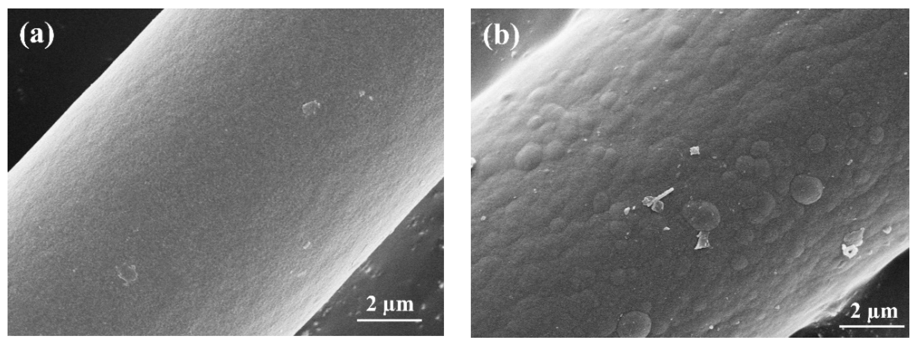
Figure 3.
XRD patterns of the fibers without (a) and with (b) SiC coatings.
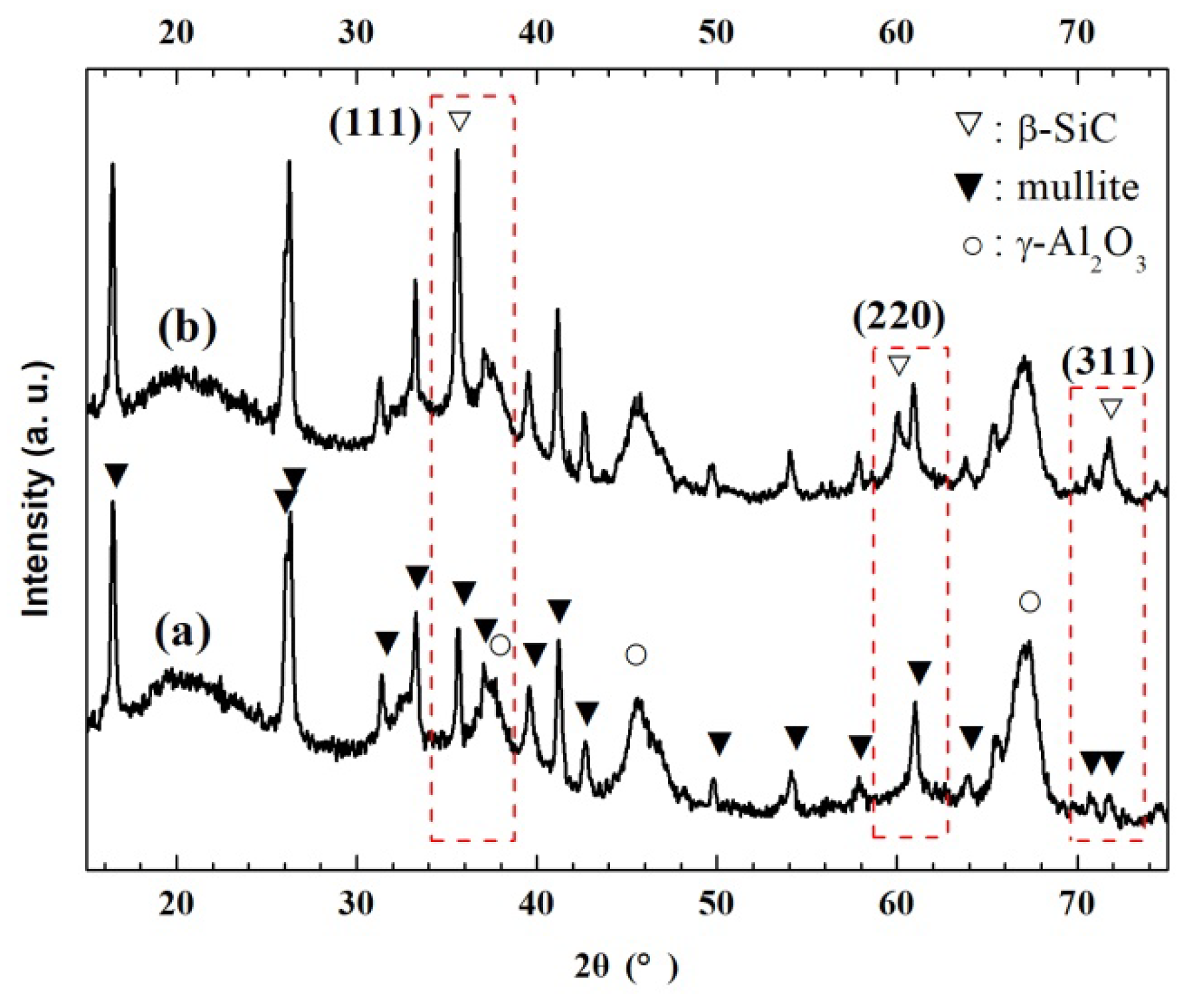
Figure 4.
XPS analysis of the fibers: (a) survey scan of as-received ones and those with coatings, (b) C 1s spectra and (c) Si 2p spectra of those with coatings.
Figure 4.
XPS analysis of the fibers: (a) survey scan of as-received ones and those with coatings, (b) C 1s spectra and (c) Si 2p spectra of those with coatings.
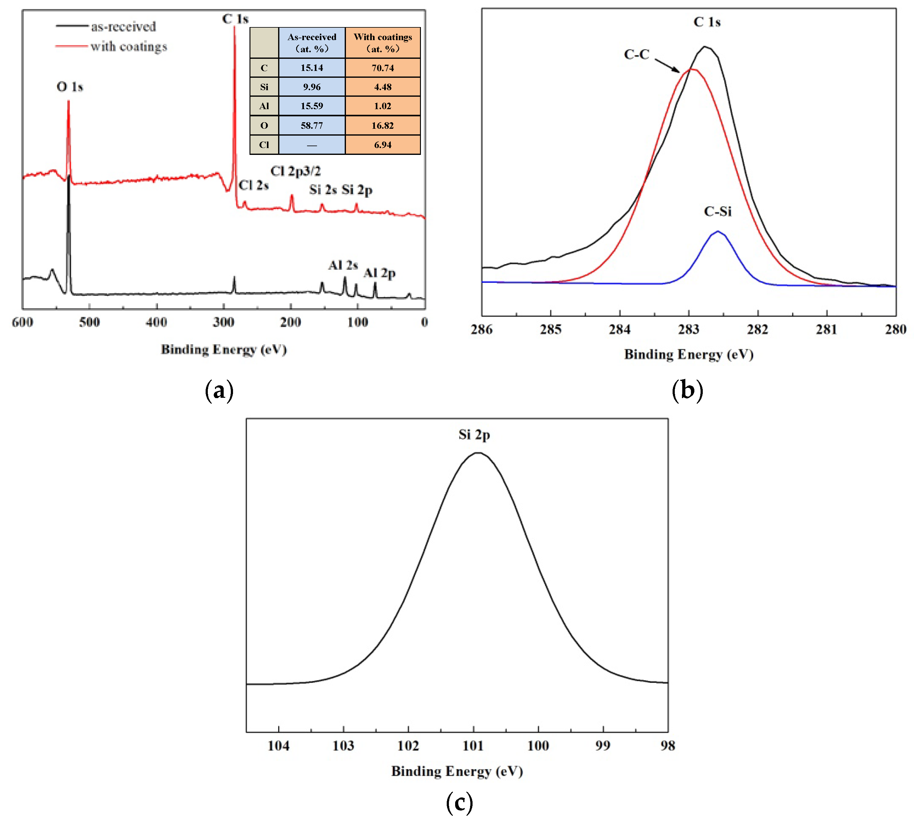
Figure 5.
TEM analysis of the fibers with coatings deposited for 2 h: (a) HR-TEM image and (b) SAED pattern of coatings.
Figure 5.
TEM analysis of the fibers with coatings deposited for 2 h: (a) HR-TEM image and (b) SAED pattern of coatings.

Figure 6.
Cross-sectional morphology of the coatings deposited for: (a) 1 h, (b) 2 h and (c) 4 h.

Figure 7.
Measured thickness and theoretical thickness of the coatings deposited for different amounts of time.
Figure 7.
Measured thickness and theoretical thickness of the coatings deposited for different amounts of time.

Figure 8.
Surface morphology and EDS analysis of the coatings deposited for 2 h after ultrasonic treatment: (a) overview image, (b) detailed image with marked areas for the EDS measurement, (c) detailed image for smooth area of the fiber surface, (d) detailed image for the fracture surface, (e) EDS measurement of smooth area and (f) EDS measurement of bulges.

Figure 9.
Schematic of the deposition mechanism for SiC coatings on NextelTM440 fibers: (a) the original fiber, (b) initial stage of deposition and (c) later stage of deposition.
Figure 9.
Schematic of the deposition mechanism for SiC coatings on NextelTM440 fibers: (a) the original fiber, (b) initial stage of deposition and (c) later stage of deposition.


Table 1.
Measured thickness and theoretical thickness of the coatings.
| Deposition Time (h) | 1 | 2 | 4 |
|---|---|---|---|
| Measured thickness (nm) | 143.5 ± 14.2 | 364.2 ± 12.5 | 1542.2 ± 17.0 |
| Theoretical thickness (nm) | 181.5 | 499.3 | 2001.2 |
© 2020 by the authors. Licensee MDPI, Basel, Switzerland. This article is an open access article distributed under the terms and conditions of the Creative Commons Attribution (CC BY) license (http://creativecommons.org/licenses/by/4.0/).
Share and Cite
MDPI and ACS Style
Wang, Y.; Sun, J.; Sheng, B.; Cheng, H. Deposition Mechanism and Thickness Control of CVD SiC Coatings on NextelTM440 Fibers. Coatings 2020, 10, 408. https://doi.org/10.3390/coatings10040408
AMA Style
Wang Y, Sun J, Sheng B, Cheng H. Deposition Mechanism and Thickness Control of CVD SiC Coatings on NextelTM440 Fibers. Coatings. 2020; 10(4):408. https://doi.org/10.3390/coatings10040408
Chicago/Turabian StyleWang, Yi, Jian Sun, Bing Sheng, and Haifeng Cheng. 2020. "Deposition Mechanism and Thickness Control of CVD SiC Coatings on NextelTM440 Fibers" Coatings 10, no. 4: 408. https://doi.org/10.3390/coatings10040408
Note that from the first issue of 2016, this journal uses article numbers instead of page numbers. See further details here.