The Surface Morphology of a Ti–6Al–4V Fiber-Lasered Nitride Layer

1
State Key Laboratory of Advanced Processing and Recyling of Nonferrous Metals, Lanzhou University of Technology, Lanzhou 730050, China
2
College of Mechanical Engineering, Longdong University, Qingyang 74500, China
*
Author to whom correspondence should be addressed.
Coatings 2020, 10(5), 451; https://doi.org/10.3390/coatings10050451
Submission received: 19 March 2020
/
Revised: 29 April 2020
/
Accepted: 29 April 2020
/
Published: 6 May 2020
Abstract
:A fiber laser was used to nitride Ti–6Al–4V titanium alloy the effect of the process parameters on the surface morphology was studied. The surface chemical composition of the nitride layer and the phase of black powder on the surface were analyzed, the two-dimensional and three-dimensional surface topography of the nitride layer surface were measured, and the cross-section microstructure of the nitride layer was photographed. The effects of laser power, laser scanning speed, nozzle distance, and nitrogen flow rate on the surface morphology were studied. The experiments show that the laser power mainly affects the surface oxidation, the laser scanning speed mainly affects the surface roughness, and the nozzle distance has a great influence on the surface morphology. The gas flow rate, however, had a slight effect on the surface morphology. A large heat input and a high nitrogen flow rate caused an increase in TiN and TiO2 black powders. Surface oxidation did not affect the formation of a continuous TiN layer nor surface roughness. Finally, the critical energy density leading to increased surface roughness was calculated.
1. Introduction
The traditional steam turbine blade is made of stainless steel. With the development of steam turbine technology, the blade became larger and heavier; this meant that the centrifugal force of the turbine was close to the allowable stress of the stainless steel. Because of its high specific strength [1], titanium alloy is an ideal material to use instead of stainless steel. However, the poor surface hardness and wear resistance of titanium alloy limit its application in turbine blades.
The laser nitriding process can quickly form a nitride layer metallurgically bonded with the titanium substrate and improve the surface hardness and wear resistance [2,3]. Many scholars have conducted research on laser nitriding of titanium alloys. The microstructure and components of the nitride layer are related to laser power, laser scanning speed, and nitrogen gas flow rate [4]. The nitride layer’s properties and morphology are a function of such processing parameters as laser power and laser scanning speed [5,6]. Process parameters are very important for the nitride layer; however, different scholars have come to different conclusions about them. Kamat et al. [7] found that high CO2 laser power can cause nitrogen ionization and increase the nitrogen content in the nitride layer, and Yilbas et al. [8] reported that cracks were not observed at low laser power. Sathish et al. [9] found that a high laser scanning speed made the nitride layer smooth and crack-free, whereas Singh et al. [10] reported that a low scanning speed can increase the hardness. Chen [11] believe that a low nitrogen gas flow rate is beneficial to nitriding quality. Abboud [12] found that a high nitrogen flow rate leads to a deep nitride layer. Our previous experiments show that the nozzle distance has a great influence on the nitride layer’s quality.
The above research results were obtained from CO2 and a semiconductor laser, and these lasers are only suitable for the nitriding of regular titanium alloy samples. The laser-head of the fiber laser is easily mounted on the arm of an industrial robot, and this then enables the nitriding of turbine blades with complex shapes and different thicknesses. At present, there are some research achievements on the fiber laser nitriding of titanium alloy [13,14,15], while there is still little research about the effect of fiber laser process parameters on the nitride layer. The fiber laser has its own characteristics [16], and a systematic study is therefore required.
The surface morphology will affect the flow of fluid on the turbine blade’s surface significantly, and this then affects the blade’s efficiency and service life. The effects of fiber laser power, laser scanning speed, nitrogen flow rate, and nozzle distance on the surface morphology of the nitride layer were studied in this research project.
2. Materials and Methods
The experiment was conducted in an open atmosphere, without enclosures or oxygen shielding devices. The schematic of the experimental setup is shown in Figure 1. Experiments were carried out with a 4.0 kW continuous wave fiber laser manufactured by IPG Laser Corp (Oxford, MA, USA). The laser model was YLS-4000. The beam was produced by a yttritm doped fiber laser oscillator and was 1064 nm in wavelength. It was guided with a fiber and focused using zinc selenide. The beam diameter at focus was 3 mm, and the beam energy was Gaussian distribution. The off-focal distance was 5 mm. High-purity nitrogen (99.99% pure; the other 0.01% being air) was used. The nitrogen flow was coaxial with the laser beam. Ti–6Al–4V slabs with a thickness of 8 mm were machined into a sample measuring 100 mm × 80 mm × 8 mm. The chemical composition of Ti–6Al–4V is shown in Table 1.
X-ray diffraction (XRD) analyses were conducted on the top surface of the nitride layer and black powders using Bruker D8 Advance XRD system (Billerica, MA, USA) with automatic slits set to 0.6 mm and a beam mask of 6 mm. An electron probe micro-analyzer (EPMA, Shimadzu EPMA-1600, Kyoto, Japan) was used to analyze the chemical composition of the nitride layer surface. The line scanning direction was parallel to the direction of the moving beam, and the scanning distance was 2 mm. The accelerating voltage was 12 kV. A three-dimensional profilometer (Alicona InfiniteFocus G4, Bruker) was used on the top surfaces of nitride layer to get the surface topography parameters of the two-dimensional and three-dimensional surface topography. To observe the microstructure in the cross-section, standard metallographic techniques (sectioning, mounting, manual grinding, and automatic polishing) were utilized, and scanning electron microscopy (SEM, JSM-6700F, JEOL, Tokyo, Japan) was performed on the cross-section of the nitride sample.
The process parameters are shown in Table 2. The effects of laser power, laser scanning speed, nozzle distance, and nitrogen flow rate on the surface morphology of the nitride layer were studied.
3. Results and Discussion
3.1. Effect of Laser Power on Surface Morphology
Nitriding experiments were carried out with different laser powers. The process parameters are given in group 1 in Table 2. The nitride layer is shown in Figure 2a. There were black powders on the surface, which weakly adhered to titanium alloy and could be easily wiped off with a towel. The powders were collected and analyzed by XRD, and the result is shown in Figure 3a. The powders were composed of a large amount of TiN and a small amount of TiO2. These powders formed from the reaction of titanium vapor with nitrogen and oxygen and were then pushed to the surface of the sample by nitrogen flow. The oxygen was composed of impurities in the nitrogen and the atmosphere invading the nitrogen protection area. Black powder was also reported by Nassar et al. [17], who performed CO2 laser nitriding of titanium alloy. The absorption rate of titanium alloy when using the long-wave CO2 laser was relatively low [18] and the melting pool temperature was low, so the amount of black powder was less than observed in this study. In order to prevent the laser reflected on the molten pool from entering into the laser nozzle and causing damage to the laser equipment, the angle between the laser-head and workpiece was 85°, as shown in Figure 1. Therefore, the black powders shown in Figure 2a were attached to the same side of the nitride layer. Point B of Figure 2a was analyzed by XRD (the result is shown in Figure 3b) and is a stoichiometric TiN, another golden-yellow nitride layer surface, which has a similar phase in this study.
In Figure 2a, the surface of the nitride layer has obvious oxidation marks from when the laser power was 1.8~2.0 kW. When the EPMA was used to analyze the oxygen content of points A and B in Figure 2a, the EPMA line scanning direction was parallel to the direction of the laser’s movement, and the scanning distance was 2 mm. The results are shown in Figure 4a. The oxygen content of point A was significantly higher than that of point B because the power and the heat input of point A was too high. After the laser beam was removed, nitrogen protection was lost, and the nitride layer was still at a high temperature; then point A was oxidized. Therefore, the laser power should not be too high, or a vacuum chamber or an auxiliary gas protection system should be used [7]. In this study, the oxygen content of the golden-yellow nitride layer and the Ti–6Al–4V substrate was similar to that at point B of Figure 2a.
In Figure 2a, the nitride layer has a small pit at the end when the laser power is 1.4~2.0 kW. The maximum depth of the pit is about 0.3 mm. This is similar to the arc crater of arc welding [11]. The nitrogen flow continued for 4 s after the laser stopped at the end of the nitride layer, and pits resulted from the nitrogen flow pushed into the molten pool. No cracks were found on any nitride layer surface.
The laser power mainly affected the surface oxidation, which would be serious if the laser power is too high. Under the experimental conditions of this study, the relatively ideal morphology of the nitride layer was obtained when the laser power was 1.2~1.6 kW and the line energy was 120~160 J/mm.
3.2. Effect of Laser Scanning Speed on Surface Morphology
Nitriding experiments were carried out with different laser scanning speeds. The process parameters are given in group 2 in Table 2. The nitride layer is shown in Figure 2b. The former part of the nitride layer did not melt due to the small heat input when the laser scanning speed was 20~60 mm/s, but the latter part did melt due to heat accumulation.
Black powders were also found in this group of experiments. It is worth noting that there were not only black powders next to the nitride layer but also on the upper surface of the nitride layer when the laser scanning speed was 3 mm/s. The black powders had tightly adhered to the nitride layer’s surface, and could not be wiped off with a towel. The low scanning speed and large heat input made the molten pool’s lifetime longer; the powders covered the surface of the unsolidified molten pool and solidified together with the molten pool, so their adhesive force was relatively strong. Figure 2a,b show that a large heat input leads to more titanium vapors and black powders.
In Figure 2b, the surface roughness of the nitride layer significantly changed when the laser scanning speed was different. The two-dimensional surface topography of the nitride layer’s surface along the A-A line in Figure 2b is shown in Figure 5. The surface topography parameters between the B-B line and the C-C line in Figure 2b are shown in Figure 6, and the three-dimensional surface topography of point E and F in Figure 2c is shown in Figure 7a,b. It can be seen in Figure 5, Figure 6, and Figure 7a,b that too high or too low a laser scanning speed led to an increase in surface roughness. In Figure 6, it can be seen that the variation tread of Sa, Sq, and Sz is similar. The Sq of the 3 mm/s nitride layer was high at 154. The large heat input resulted from a low laser scanning speed, and a large amount of titanium evaporated from the molten pool. The reactive force of titanium vapor impacted upon the surface of the molten pool and led to an increase in surface roughness. The Sq of the 10 and 20 mm/s nitride layers was 36 and 38, respectively, with a moderate laser scanning speed and heat input. The molten pool was shocked under the action of nitrogen flow when the laser scanning speed was 30 mm/s and rapidly solidified because of the small heat input. The surface morphology remained in a shock process, so the Sq was high at 84. The molten pool was too shallow to shock given the high laser scanning speed and small heat input. The Sq of the 40, 50, and 60 mm/s nitride layers was 42, 39, and 38, respectively.
The laser scanning speed mainly affects the surface roughness. If the laser scanning speed is too high or low, the surface will be rough. Under the experimental conditions in this study, the nitride layer’s surface was smooth when the laser scanning speed was 10~20 mm/s and the line energy was 70~140 J/mm.
3.3. Effect of Nozzle Distance on Surface Morphology
Nitriding experiments were carried out with different nozzle distances. The process parameters are given in group 3 in Table 2. The nitride layer is shown in Figure 2c. The surface morphology of the nitride layer was good when the nozzle distance was 3~5 mm, while it seriously deteriorated when the nozzle distance was 6~8 mm. The EPMA was used to analyze the oxygen content of points A and B in Figure 2c. The line scanning direction was parallel to the direction of the laser’s movement, and the scanning length was 2 mm. The result is shown in Figure 4b. The oxygen content of point A is higher than that of point B, and the large nozzle distance of point A led to oxygen in the air invading the nitrogen protection area and the nitride layer was oxidized. The three-dimensional surface topography of point A in Figure 2c is shown in Figure 7c. The surface of point A is relatively smooth though heavily oxidized, which proves that surface oxidation does not affect the roughness. Similar conclusions can be obtained by other experiments.
It can be seen from Figure 7a,c that the middle region is smooth and that both sides of the nitride layer are rough. In this study, all nitride layers with a smooth surface show similar characteristics. The rough area of both sides was caused by the small heat input. The three-dimensional surface topography of point B in Figure 2c is shown in Figure 7d. In this study, the laser energy was in a Gaussian distribution. The two-dimensional Gaussian heat source energy distribution is drawn to scale in Figure 7c. The laser energy density at point A in Figure 7c is 3.1 × 10⁴ W/cm2 calculated with Matlab software (R2018a). It can be concluded that a laser power density less than 3.1 × 10⁴ W/cm2 will lead to an increase in surface roughness. Other experiments in this study yielded approximately the same energy density. We can improve the overlap rate of the nitride layer to eliminate the roughness regions on both sides.
The effect of the nozzle distance on the surface morphology is relatively serious. Under the experimental conditions of this study, the nozzle distance must be strictly controlled at 3~5 mm to obtain excellent surface morphology.
3.4. Effect of Nitrogen Flow Rate on Surface Morphology
Nitriding experiments were carried out with different nitrogen flow rates. The process parameters are given in group 4 in Table 2. The surface morphology is shown in Figure 2d. The surface color of the nitride layer was slightly darker when the nitrogen flow rate was 20~23 L/min. A small amount of oxidation occurred as the high nitrogen flow rate drew air into the nitride region [12]. The high nitrogen flow rate pushed more black powders to the surface of the sample, as shown in Figure 2d.
The nitride layer shows that TiN’s characteristic golden-yellow color and the surface are well formed when the nitrogen flow rate is 2~15 L/min. The cross-section of the microstructure at point A in Figure 2d is shown in Figure 8b. There is a continuous TiN layer on the upper surface with a thickness of about 3~5 μm. The continuous TiN layer is formed due to crystal growth in a planar manner, the high nitrogen content, and the high heat dissipation rate on the upper surface. There was 3~5 μm of continuous TiN on the top of all nitride layers in all of the experiments. Other researchers found similar continuous TiN layers with the thicknesses of 1~3 μm [19], 3 μm [7], and several hundred nanometers to several microns [20], which depend on process parameters and laser modes. The continuous TiN layer has a high proportion of nitrogen content and excellent hardness and wear resistance. The oxidation of point A in Figure 2a is serious, and the cross-section micrograph is shown in Figure 8a. There remains a continuous TiN layer, which proves that surface oxidation does not affect the formation of a continuous TiN layer.
The nitrogen flow rate had little influence on the surface morphology. Under the experimental conditions of this study, we recommend a nitrogen flow of 5~10 L/min.
3.5. Mechanism Analysis
Both laser power and scanning speed affect the heat input of the substrate, and then affect the surface morphology. The laser power mainly affects the laser power density, and then affects the molten pool’s lifetime. A longer molten pool lifetime will severely oxidize the nitride layer.
The laser scanning speed mainly affects the relationship between the molten pool’s shock time and the molten pool’s lifetime. If the molten pool’s shock time is equal to the molten pool’s lifetime, and the molten pool solidifies during the shock process, the surface of the nitride layer will be relatively rough. If the scanning speed is too high or too low, a rough surface can be formed.
A good surface morphology can be obtained by strictly controlling the nozzle distance to be 3~5 mm. If the nozzle distance is increased, on the one hand, the air is more likely to invade the nitrogen protection area; if, on the other hand, the laser heats the nitrogen in the nozzle significantly, the hot nitrogen will have a strong upward movement trend by buoyancy, more nitrogen will move upward, and the protection of nitrogen in the molten pool will be weak. In this case, the nitride layer will be significantly oxidized.
The nitrogen flow rate has little influence on the surface morphology. On the one hand, the thickness of the nitride layer is only several hundred microns, and a low nitrogen flow rate can provide enough nitrogen for the molten pool. On the other hand, the nozzle distance is only 3~5 mm, so the nitrogen flow can easily form a protective area. Therefore, a nitride layer with an excellent surface morphology can be obtained by using a high or low nitrogen flow rate.
4. Conclusions
A fiber laser (1064 nm) was used for the nitriding of Ti–6Al–4V titanium alloy. The effect of process parameters on the surface morphology was studied. The following conclusions were drawn:
- (1)
- The laser power mainly affects the surface oxidation of the nitride layer. High laser power causes severe surface oxidation. The laser scanning speed mainly affects the surface roughness, which will increase when the scanning speed is too high or low. The nozzle distance has a great influence on the surface morphology, so the nozzle distance must be strictly controlled at 3~5 mm for an ideal surface morphology. The nitrogen flow rate has little influence on the surface morphology, so we recommend that a low nitrogen flow rate be used. A nitride layer with an optimal surface morphology can be obtained using the process parameters of group 5 in Table 2.
- (2)
- A large heat input and a high nitrogen flow rate cause an increase in the amount of TiN and TiO2 black powders on the surface of the nitride layer.
- (3)
- Surface oxidation does not affect the formation of a continuous TiN layer and surface roughness. The critical energy density leading to an increase in roughness is less than 3.1 × 10⁴ W/cm2.
Author Contributions
Conceptualization, Y.S.; methodology, Y.S.; software, J.G.; validation, P.G., G.Z. and M.Z.; formal analysis, J.G.; investigation, J.G.; resources, J.G.; data curation, J.G.; writing—original draft preparation, J.G.; writing—review and editing, J.G.; visualization, P.G.; supervision, P.G.; project administration, G.Z.; funding acquisition, Y.S. All authors have read and agreed to the published version of the manuscript.
Funding
This research was funded by the Guide the Development of Science and Technology Innovation Special Fund Project in Gansu Province (2019ZX-08); the Opening fund of the State Key Laboratory of Advanced Processing and Recycling of Non-ferrous Metals, Lanzhou University of Technology (SKLAB02019005; the National Natural Science Foundation of China (51805234); and the Opening fund of Beijing key laboratory of poto-electromechanical equipment technology.
Conflicts of Interest
The authors declare no conflict of interest.
References
- Da Silva Briguente, N.; Aparecida, L.; Oñoro, J.; Perpétuo Briguente, F.; Assis Resende, F.; Lidovino dos Reis, J.; Pereira Reis, D.A.; de Oliveira, A.C. The influence of laser nitriding on creep behavior of Ti-4Al-4V alloy with widmanstätten microstructure. Metals 2019, 9, 236. [Google Scholar] [CrossRef] [Green Version]
- Ohtsu, N.; Yamane, M.; Kodama, K.; Wagatsuma, K. Surface hardening of titanium by pulsed Nd: YAG laser irradiation at 1064-and 532-nm wavelengths in nitrogen atmosphere. Appl. Surf. Sci. 2010, 257, 691–695. [Google Scholar] [CrossRef]
- Kamat, A.M.; Copley, S.M.; Segall, A.E.; Todd, J.A. Laser-sustained plasma (LSP) nitriding of titanium: A review. Coatings 2019, 9, 283. [Google Scholar] [CrossRef] [Green Version]
- Hu, C.; Xin, H.; Watson, L.M.; Baker, T.N. Analysis of the phases developed by laser nitriding Ti6Al4V alloys. Acta Mater. 1997, 45, 4311–4322. [Google Scholar] [CrossRef]
- Singh, R.; Kurella, A.; Dahotre, N.B. Laser surface modification of Ti–6Al–4V: Wear and corrosion characterization in simulated biofluid. J. Biomater. Appl. 2006, 21, 49–73. [Google Scholar] [CrossRef] [PubMed]
- Singh, R.; Martin, M.; Dahotre, N.B. Influence of laser surface modification on corrosion behavior of stainless steel 316L and Ti–6Al–4V in simulated biofluid. Surf. Eng. 2005, 21, 297–306. [Google Scholar] [CrossRef]
- Kamat, A.M.; Copley, S.M.; Todd, J.A. Effect of processing parameters on microstructure during laser-sustained plasma (LSP) nitriding of commercially-pure titanium. Acta Mater. 2016, 107, 72–82. [Google Scholar] [CrossRef]
- Yilbas, B.S.; Karatas, C.; Keles, O.; Usta, I.Y.; Ahsan, M. CO2 laser gas assisted nitriding of Ti–6Al–4V alloy. Appl. Surf. Sci. 2006, 252, 8557–8564. [Google Scholar] [CrossRef]
- Sathish, S.; Geetha, M.; Pandey, N.D.; Richard, C.; Asokamani, R. Studies on the corrosion and wear behavior of the laser nitrided biomedical titanium and its alloys. Mater. Sci. Eng. C 2010, 30, 376–382. [Google Scholar] [CrossRef]
- Singh, S.; Tiwari, S.K.; Singh, R. Influence of laser scanning speed on nitrided Ti6Al4V surface. Surf. Eng. 2017, 9, 1–9. [Google Scholar] [CrossRef]
- Chen, X.; Wu, G.; Wang, R.; Guo, W.; Yang, J.; Cao, S.; Wang, Y.; Han, W. Laser nitriding of titanium alloy in the atmosphere environment. Surf. Coat. Technol. 2007, 201, 4843–4846. [Google Scholar] [CrossRef]
- Abboud, J.H.; Fidel, A.F.; Benyounis, K.Y. Surface nitriding of Ti–6Al–4V alloy with a high power CO2 laser. Opt. Laser Technol. 2008, 40, 405–414. [Google Scholar] [CrossRef]
- Chan, C.-W.; Lee, S.; Smith, G.C.; Donaghy, C. Fibre laser nitriding of titanium and its alloy in open atmosphere for orthopaedic implant applications: Investigations on surface quality, microstructure and tribological properties. Surf. Coat. Technol. 2017, 309, 628–640. [Google Scholar] [CrossRef] [Green Version]
- Katahira, K.; Tanida, Y.; Takesue, S.; Komotori, J. Rapid surface nitriding of titanium alloy by a nanosecond fiber laser under atmospheric conditions. Cirp Ann. 2018, 67, 563–566. [Google Scholar] [CrossRef]
- Ng, C.-H.; Chan, C.-W.; Man, H.-C.; Waugh, D.; Lawrence, J. Modifications of surface properties of beta Ti by laser gas diffusion nitriding. J. Laser Appl. 2016, 28, 022505. [Google Scholar] [CrossRef]
- Meng, W.; Xu, Z.; Ma, Q.; Yin, X.; Fang, J. Pulse fiber laser welding of AISI 321-AISI 405 stainless steel thick plates butt joints. J. Mater. Process. Technol. 2019, 271, 214–225. [Google Scholar] [CrossRef]
- Nassar, A.R.; Akarapu, R.; Copley, S.M.; Todd, J.A. Investigations of laser-sustained plasma and its role in laser nitriding of titanium. J. Phys. D Appl. Phys. 2012, 45, 185401. [Google Scholar] [CrossRef]
- Thomann, A.L.; Boulmer-Leborgne, C.; Andreazza-Vignolle, C.; Andreazza, P.; Hermann, J.; Blondiaux, G. Metal surface nitriding by laser induced plasma. J. Appl. Phys. 2012, 80, 4673–4684. [Google Scholar] [CrossRef]
- Kloosterman, A.B.; Hosson, J.T.M.D. Microstructural characterization of laser nitrided titanium. Scr. Metall. Et Mater. 1995, 33, 567–573. [Google Scholar] [CrossRef] [Green Version]
- Kaspar, J.; Bretschneider, J.; Jacob, S.; Bonß, S.; Winderlich, B.; Brenner, B. Microstructure, hardness and cavitation erosion behaviour of Ti–6Al–4V laser nitrided under different gas atmospheres. Surf. Eng. 2007, 23, 99–106. [Google Scholar] [CrossRef]
Figure 1.
Schematic of the experimental setup.
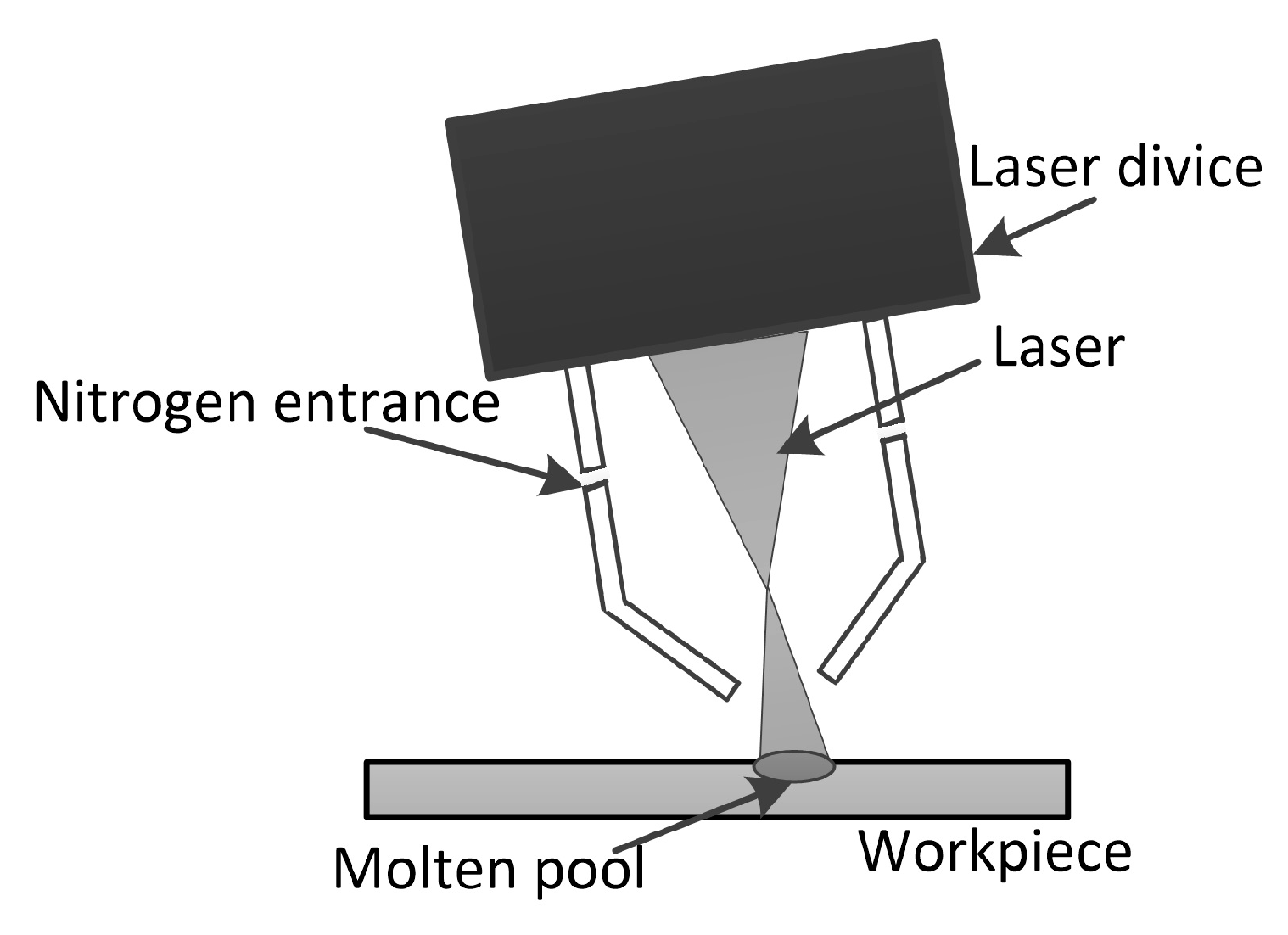
Figure 2.
Top view of the nitride layer: (a) different powers; (b) different scanning speeds; (c) different nozzle distances; and (d) different nitrogen flow rates.
Figure 2.
Top view of the nitride layer: (a) different powers; (b) different scanning speeds; (c) different nozzle distances; and (d) different nitrogen flow rates.

Figure 3.
XRD spectra: (a) black powders; (b) point B of Figure 2a.
Figure 3.
XRD spectra: (a) black powders; (b) point B of Figure 2a.

Figure 4.
Surface oxygen content analyzed by electron probe micro-analyzer (EPMA) line scanning of (a) Point A and B in Figure 2a; (b) Point A and B in Figure 2c.
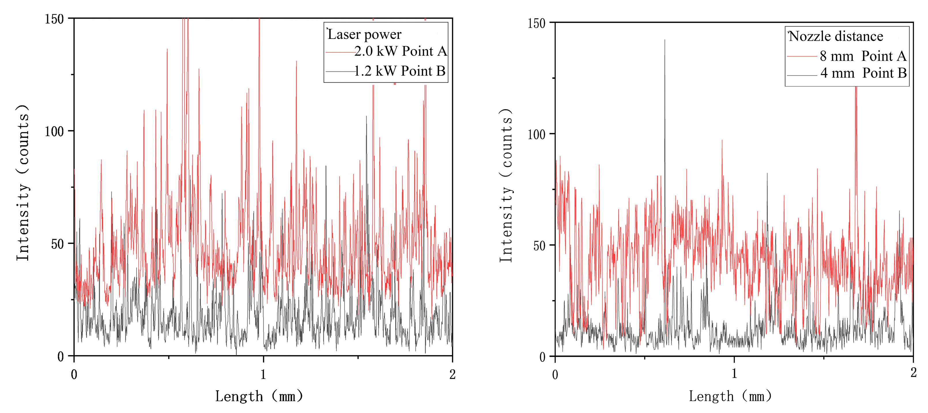
Figure 5.
The two-dimensional contour morphology of the nitride layer’s surface in Figure 2b.
Figure 5.
The two-dimensional contour morphology of the nitride layer’s surface in Figure 2b.
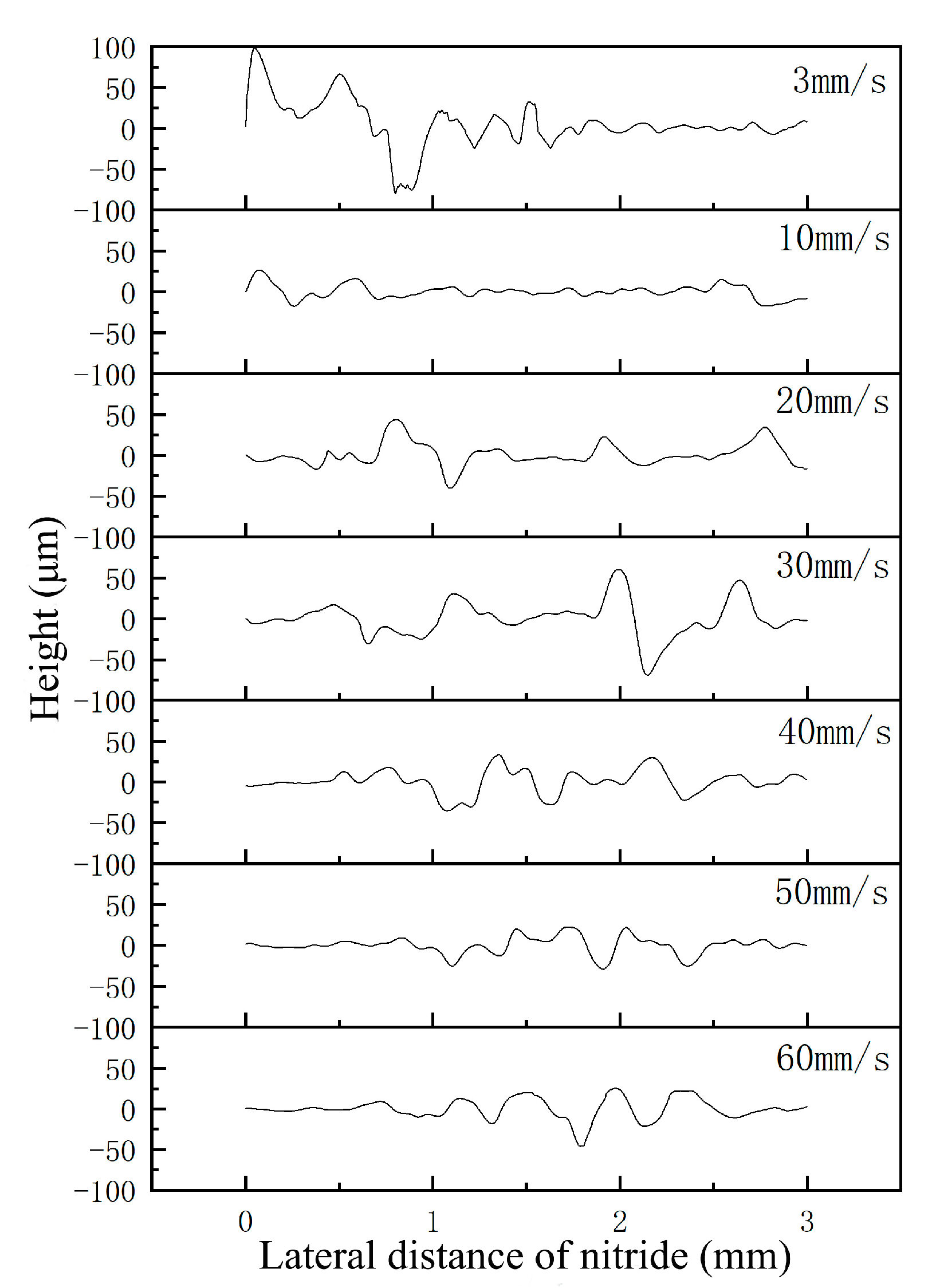
Figure 6.
Surface topography parameters of the nitride layer in Figure 2b.
Figure 6.
Surface topography parameters of the nitride layer in Figure 2b.
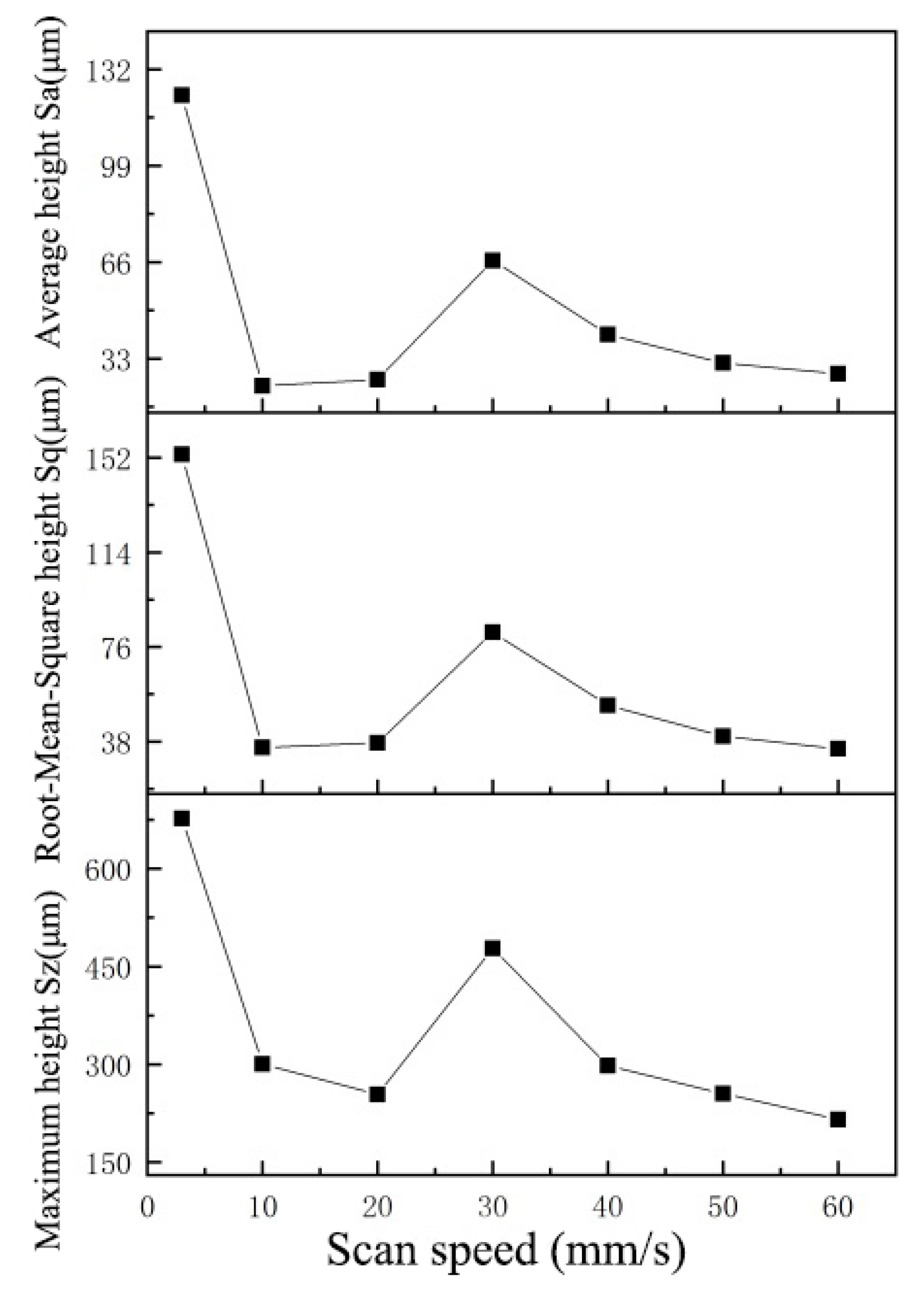
Figure 7.
Three-dimensional surface topography: (a) point E in Figure 2b; (b) point F in Figure 2b; (c) point A in Figure 2c; (d) point B in Figure 2c and the Gaussian heat source distribution.
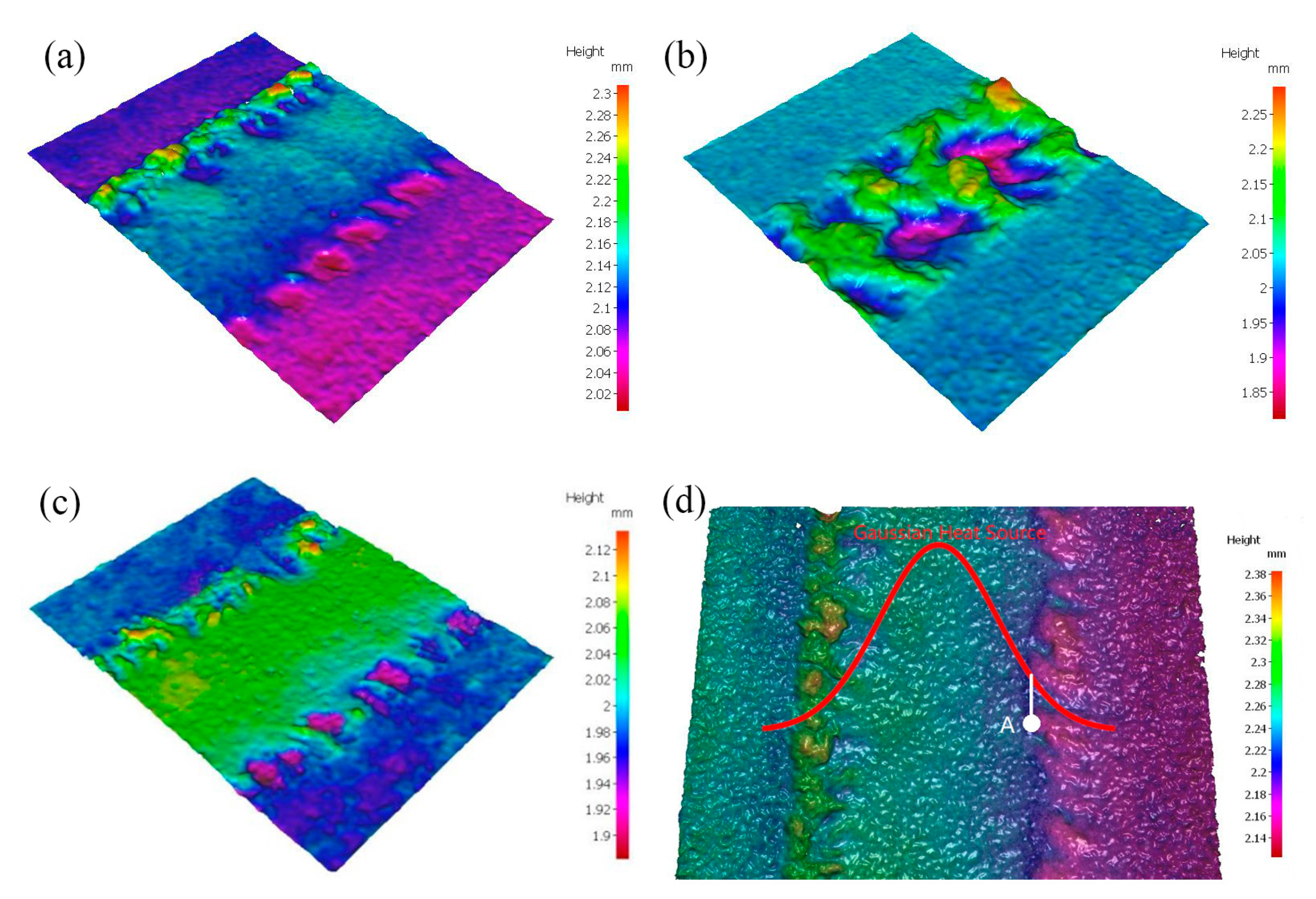
Figure 8.
Micrograph of the transverse cross-section: (a) point A of Figure 2a; (b) point A of Figure 2d.


Table 1.
Chemical composition of Ti–6Al–4V titanium alloy.
| Element | Al | V | Fe | C | N | H | Ti |
|---|---|---|---|---|---|---|---|
| Concentration (wt.%) | 5.7 | 3.9 | 0.3 | 0.1 | 0.05 | 0.015 | Others |
Table 2.
Process parameters.
| Group | Power (kW) | Scanning Speed (mm/s) | Nozzle Distance (mm) | Nitrogen Flow Rate (L/min) |
|---|---|---|---|---|
| 1 | 1.0/1.2/1.4/1.6/1.8/2.0 | 10 | 3 | 10 |
| 2 | 1.4 | 3/10/20/30/40/50/60 | 3 | 10 |
| 3 | 1.4 | 10 | 3/4/5/6/7/8 | 10 |
| 4 | 1.4 | 10 | 3 | 2/5/10/15/20/23 |
| 5 | 1.4 | 10 | 3 | 10 |
© 2020 by the authors. Licensee MDPI, Basel, Switzerland. This article is an open access article distributed under the terms and conditions of the Creative Commons Attribution (CC BY) license (http://creativecommons.org/licenses/by/4.0/).
Share and Cite
MDPI and ACS Style
Guo, J.; Shi, Y.; Geng, P.; Zhang, G.; Zhu, M. The Surface Morphology of a Ti–6Al–4V Fiber-Lasered Nitride Layer. Coatings 2020, 10, 451. https://doi.org/10.3390/coatings10050451
AMA Style
Guo J, Shi Y, Geng P, Zhang G, Zhu M. The Surface Morphology of a Ti–6Al–4V Fiber-Lasered Nitride Layer. Coatings. 2020; 10(5):451. https://doi.org/10.3390/coatings10050451
Chicago/Turabian StyleGuo, Jinchang, Yu Shi, Peibiao Geng, Gang Zhang, and Ming Zhu. 2020. "The Surface Morphology of a Ti–6Al–4V Fiber-Lasered Nitride Layer" Coatings 10, no. 5: 451. https://doi.org/10.3390/coatings10050451
Note that from the first issue of 2016, this journal uses article numbers instead of page numbers. See further details here.