Article

Mechanical Properties of Arc Coatings Sprayed with Cored Wires with Different Charge Compositions

by
Mykhailo Student
1,
Volodymyr Hvozdetskyi
1,
Taras Stupnytskyi
1,
Oleksandra Student
1,
Pavlo Maruschak
2,
Olegas Prentkovskis
3,* and
Paulius Skačkauskas
3
1
Karpenko Physico-Mechanical Institute of the NAS of Ukraine, 5 Naukova St., 79060 Lviv, Ukraine
2
Department of Industrial Automation, Ternopil National Ivan Puluj Technical University, Rus’ka Str. 56, 46001 Ternopil, Ukraine
3
Department of Mobile Machinery and Railway Transport, Vilnius Gediminas Technical University, Plytines g. 27, LT-10105 Vilnius, Lithuania
*
Author to whom correspondence should be addressed.
Coatings 2022, 12(7), 925; https://doi.org/10.3390/coatings12070925
Submission received: 11 May 2022 / Revised: 25 June 2022 / Accepted: 27 June 2022 / Published: 30 June 2022

Abstract

:
The mechanical properties (hardness, cohesion, and residual stresses) of arc coatings designed for operation under conditions of boundary friction and corrosive-abrasive wear are analyzed. The coatings were formed by arc spraying cored wires (CW) with different charge compositions (the content of carbon, aluminum, and boron in CW charge varied). It is shown that the hardness of the coatings increases with an increase in the carbon content in them up to 1 wt. %, and then decreased due to an increase in the content of residual austenite in their structure. The level of residual stresses of the first kind in such coatings increased by four times with an increase in the carbon content to 2 wt. %. The hardness of the coatings and the level of residual tensile stresses in them also increase with a decrease in the aluminum content in them. In this case, the cohesive strength of the coatings increased due to the implementation of aluminothermic reactions in the droplets of the CW melt during their flight and crystallization on the sprayed surfaces. However, then, with an increase in the aluminum content in the coatings of more than 2 wt. %, their cohesive strength decreased. The level of residual tensile stresses in coatings with a high content of retained austenite decreased after heat treatment (tempering) of the specimens. Sometimes, after tempering, these stresses even transformed into residual compressive stresses (in particular, under using CW C1.4Cr14Ni2). At the same time, the tempering of specimens with a predominance of ferrite in the coating structure increased the level of residual tensile stresses in them, which is due to the precipitation of finely dispersed carbides or borides. It has been shown that the addition of boron-containing components (ferrochromium-boron, chromium-boron) to the composition of the CW charge leads to a significant increase in the hardness of the coatings. Thus, an increase in the boron content in coatings from 0 to 4 wt. % leads to an increase in their hardness from 320 HV to 1060 HV. However, this is accompanied by an increase in tensile residual stresses in the coatings and a decrease in their cohesive strength.

1. Introduction

To restore and extend the service life of various shaft-type elements, methods of thermal spraying of coatings have recently become widely used in world practice [1,2,3,4,5]. Arc spraying is one of the cheapest and simplest methods of thermal spraying, which does not require expensive equipment [6,7]. The use of cored wires (CW) for arc spraying (AS) made it possible to use such coatings for protection from gas corrosion [8,9,10,11,12,13,14], against gas-abrasive wear of heating elements of boilers of thermal power plants [15,16,17] and for the restoration of various wear parts, in particular, shafts of transport and agricultural machines, food industry compressors operating under boundary friction [18], and corrosion-abrasive wear [19,20,21,22]. Stainless solid wires from steels 40Cr13 and 08Cr18N10T are often used as electrode materials for AS of anticorrosion coatings. The disadvantages of these coatings are the high cost and low hardness and wear resistance. CW with the appropriate chemical composition is at least half the price. The trouble-free operation of parts of various machines, restored or protected by arc spray coatings (ASC), largely depends on their mechanical properties [23,24,25], which are predetermined by the content of alloying elements in them [26,27]. Therefore, the purpose of this study is to study the effect of alloying elements in ASC with CW of various alloying systems on their mechanical properties.

2. Materials and Methods

2.1. Deposition

ASC with a thickness of 1.2 mm was deposited using a metallizer (development of the Karpenko Physico-Mechanical Institute of the NAS of Ukraine). As charge materials in the manufacture of CW with a diameter of 1.8 mm, ferroalloys and pure metals were used. A steel (0.08 wt. % C) strip 0.4 mm thick and 10 mm wide was used for the CW shell (Figure 1).
The fill factor of CW with charge was 22%–30%. Coating mode: current 150 A, arc voltage 32…34 V. CW was sprayed with a flow of compressed air at a pressure of 0.6 MPa from a distance of 150 mm. On the example of a number of CWs with fundamentally different charge compositions, the spraying mode of coatings was optimized [28]. This mode was actually used in this article. The choice of the same spraying mode made it possible to provide almost the same size, speed, temperature, and, accordingly, the cooling rate of the droplets of the CW melt sprayed onto the base surface. The mechanical properties of arc coatings essentially depend on these parameters of the droplets of the CW melt. Changing the coating deposition parameters (arc current and voltage, spraying flow pressure) significantly affects the parameters of the melted droplets. Such a variation in the spraying parameters of coatings could strongly mask the regularities in the influence of the component composition of the CW charge on the mechanical properties of the coatings. The same mode of all the analyzed coatings was chosen precisely in order to exclude its effect on the mechanical properties of the coatings. Indeed, with the same diameter of all used CW, the influence of the coating deposition mode can be neglected.
The microstructure and chemical composition of the coatings were studied using a Carl Zeiss EVO XVP 40 electron microscope with an INCA Energy 350 X-ray spectral microanalyzer (Oxford Instruments). Their phase compositions were studied in CuKα radiation on a DRON-3 diffractometer at a voltage of 31 kV with an estimation step of 0.05°. The diffraction pattern profiles were refined by the Rietveld method with two different pseudo-Voigt function using Powder Cell 2.4 program [29].

2.2. Assessment of Internal Stresses in Coatings

These stresses in the coatings were measured on a ring with a diameter of 60 mm, a height of 20 mm, and a wall thickness of 4 mm. A coating 1 mm thick was sprayed onto its outer surface. The edges of the longitudinal through cut on the ring moved relative to each other when the coating was deposited on its outer surface. Their displacement dK was measured experimentally. The residual stress in the ASC was calculated according to the procedure proposed for a bimetallic ring with a ratio of the radius at the center of its wall thickness to its thickness of at least ten [30,31]. To determine the residual stresses σRS arising in the coatings, the following expressions were used, taking into account the differences in the elastic moduli of the steel ring-substrate and the deposited ASCs:
σ R S = 2 E 1 D 2 B H + d h Δ D ,
Δ D = Δ K π  
B = 0.5 t 2 2 c + t 1 2 + 2 t 1 t 2 c t 2 c + t 1  
c = E 2 E 1
ΔD is the outer diameter of the steel ring; t1, t2 are the thickness of the steel ring and the sprayed coating, respectively; E1, E2 are the elastic moduli of the steel and the sprayed coating, respectively; h is the depth of the layer location, in which the residual stresses were determined; and K is the opening of the ends of a longitudinal through cut on the ring due to occurrence of internal stresses in the coating (Figure 2).
To determine the residual tensile stresses in the coatings, the split ring technique (Figure 3) was used, which made it possible to measure the stress in the coating during its deposition and cooling to room temperature. Rods 2 with internal grooves were welded to the ends of split ring 1 to fix strain gauge 3 in them, which was protected by screen 4 during spraying Figure 4).

2.3. Evaluation of the Cohesive Strength of Coatings

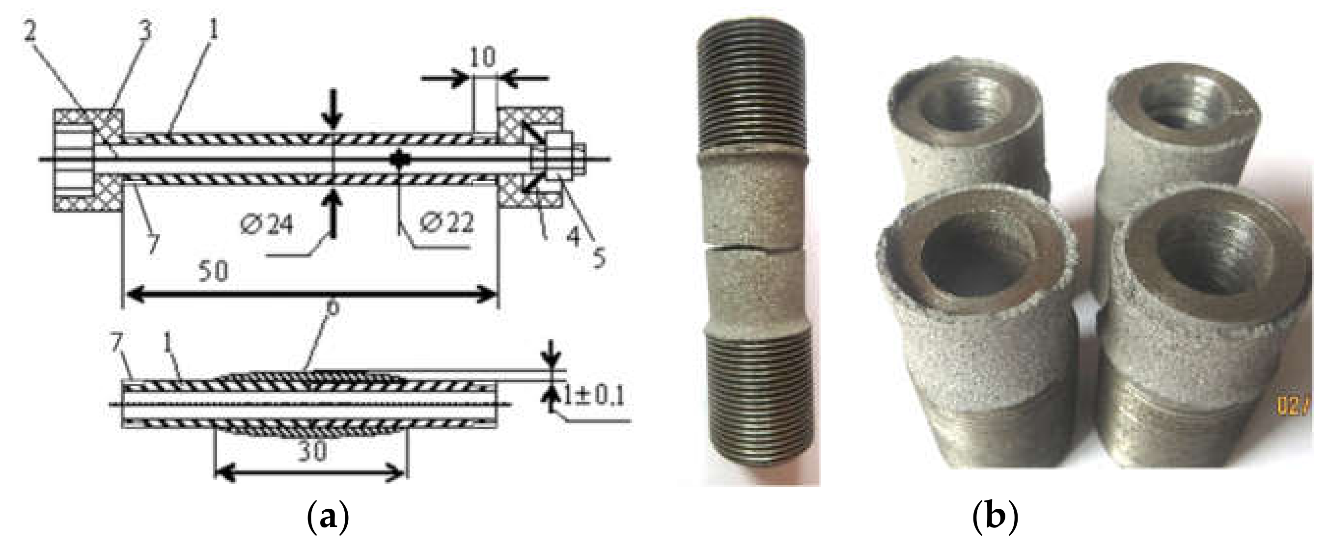
To determine it, two tubular specimens 50 mm long were used, the ends of which were pressed together by means of a bolted connection (Figure 5) [32]. A coating 1.2 mm thick was sprayed on the outer surface of the thus assembled specimen. After that, the specimen was released from the mandrel, pressing the ends of its two halves, and they continued to be held together only due to the coating on their surface. The specimen was loaded on a tensile testing machine FPZ-10, fixing the load P at the moment of destruction of the coating along the contact line of its two halves. The cohesive strength σCS of the coating was determined as σCS = P/S, taking into account the coating area S in the vicinity of the interface of the two halves of the assembled specimen.
With a confidence probability of 0.95 and at least three tests for residual stresses, fife tests for the cohesive strength and up to ten for hardness for each from analyzed coatings with CW, the relative error in determining the average values of these characteristics did not exceed 2–7%.

3. Results and Discussion

The workability of ASCs is largely determined by their hardness, cohesive strength and level of residual stresses. The porosity of coatings also affects their mechanical characteristics [28]. The deposition modes of coating (current values, distance to the sprayed surface) and the chemical composition of the CW charge have little effect on their porosity. The greatest influence on the porosity of the coatings is exerted by the diameter of the CW and the pressure of the air flow used in the spraying. Since all the coatings analyzed in this article were sprayed at the same parameters, their porosity did not exceed 2–3%.
The content of carbon, aluminum and boron in the ASC deposited by the CW determines their mechanical characteristics. The chemical composition of CW for studying the effect of carbon on the phase composition and mechanical characteristics of coatings from CW C(0.2…1.4)Cr14 with different carbon content is given in Table 1.
The phase composition of the coating changes with an increase in the carbon content in it, namely, the content of residual austenite increases in it (Table 1). In particular, when using ferrochromium FeCr (with 2 wt. % C) as the main component of the CW charge, the carbon content in the coating reached 0.25 wt. %. In this case, a small amount of residual austenite and Fe3C (only in the form of traces) and the main structural component in the form of a supersaturated solid solution of carbon in Feα (martensite with a tetragonal bcc lattice) were observed in the coating. This martensitic phase was designated as Feα(m). In this case, the phase ratio in the coating was Feα(m)/Feγ = 8/1, and Fe3C was detected only as traces. The carbon content in the coating increased to ~0.6 wt. % when replacing FeCr powder with 2 wt. % C (as the main component of the CW charge) with FeCr powder with 8 wt. % C. The amount of residual austenite in the coating also increased, and the structural component Feα was observed in the form of a supersaturated solid solution of carbon in Feα (martensite with a tetragonal bcc lattice designated as Feα(m)). With the addition to CW charge from 5 to 20 wt. % of graphite, the content of residual austenite in the coating increased, reaching a maximum at 10 wt. % graphite in the CW charge. The ratio between the phases also changed: Feα(m)/Feγ = 2/3.
As confirmation, X-ray diffraction patterns of arc coatings with CW are given below (Figure 6). They made it possible to detect Feα(m) and Feγ phases in various ratios in the structure of sprayed coatings. In the analyzed coatings, the amount of carbon varies within 0.2–2.0 wt. %. A very small amount of carbon is bound in cementite (Fe3C). The rest of carbon is contained in solid solutions of iron-Feα (as a ferrite Feα(f) and in the form of a supersaturated solid solution of carbon in Fe (martensite–Feα(m)) and Feγ. Since ferrite can only contain up to 0.02 wt. % C, the rest of the carbon is contained in a supersaturated solid solution of carbon in iron (martensite). This means that in coatings with a significant amount of carbon (0.2–2.0 wt. %), shown in Table 1, there can be practically no ferrite. Two main phases, martensite and austenite, can form in these coatings. In addition, the high hardness of the coating (up to 700 HV) with the predominance of the Feα phase in the diffraction pattern cannot be due to ferrite, since its hardness is clearly lower (does not exceed 300 HV). It can only be provided by martensite, the hardness of which can reach 1000 HV (in the case of high-carbon martensite). On this basis, martensite is considered in this article as the main factor in the structural hardening of coatings with high carbon content.
Thus, the cohesive strength σCS of coatings deposited with CW C(0.2…1.4)Cr14 doubles (from 150 to 300 MPa) with an increase in the carbon content in the coatings from 0 to 2 wt. % (Figure 7a). Its positive effect is due to the fact that carbon reacts with atmospheric oxygen (C + O2 = CO2) during the flight of dispersed drops of CW melt.
As a result, a protective atmosphere of carbon dioxide is formed around the droplets, which prevents further oxidation of their surface. Due to this, the amount of the oxide phase on the surface of the molten droplets decreases and, as a result, during their crystallization, the thickness of the oxide films between the lamellae of the deposited coating decreases. It is clear that the adhesive force between the lamellas is increased, which provides an increase in the cohesive strength of the coating. The hardness of the coating increases with an increase in the carbon content in it up to 1 wt. %, and then begins to decrease, which is associated with a rapid increase in the content of residual austenite in the coating (practically up to 100% when the carbon content in ASC is up to 1 wt. %, Figure 7b). At the same time, with an increase in the carbon content in ASC to 2 wt. % residual stresses of the first kind increased by more than three times (from 43 MPa to 160 MPa, Figure 7a). Such a high level of residual stresses promotes to the appearance of main cracks in the coating (even at the stage of its deposition), which will contribute to its delamination from the substrates
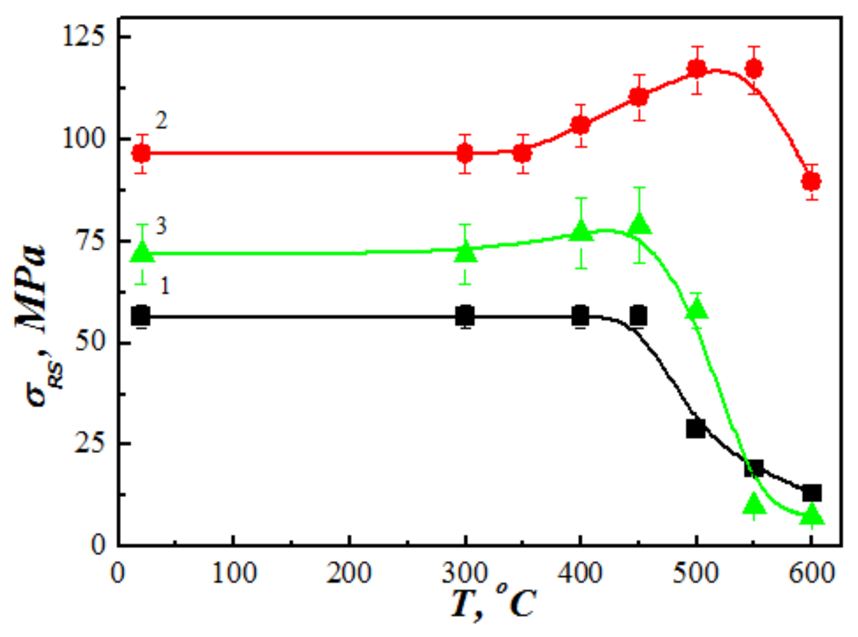
Tempering specimens with ASC at temperatures above 450 °C reduce residual tensile stresses in the coating (Figure 8). Sometimes, tempering can even transform residual tensile stresses into compressive stresses (Table 2). This is due to the fact that residual austenite in the coating structure turns into tempered martensite. The volume of newly formed martensite is almost 2.5% larger than that of austenite, which helps to reduce residual tensile stresses. Therefore, the more carbon is dissolved in austenite and the more austenite is converted to martensite, the lower the residual tensile stresses in the coating.
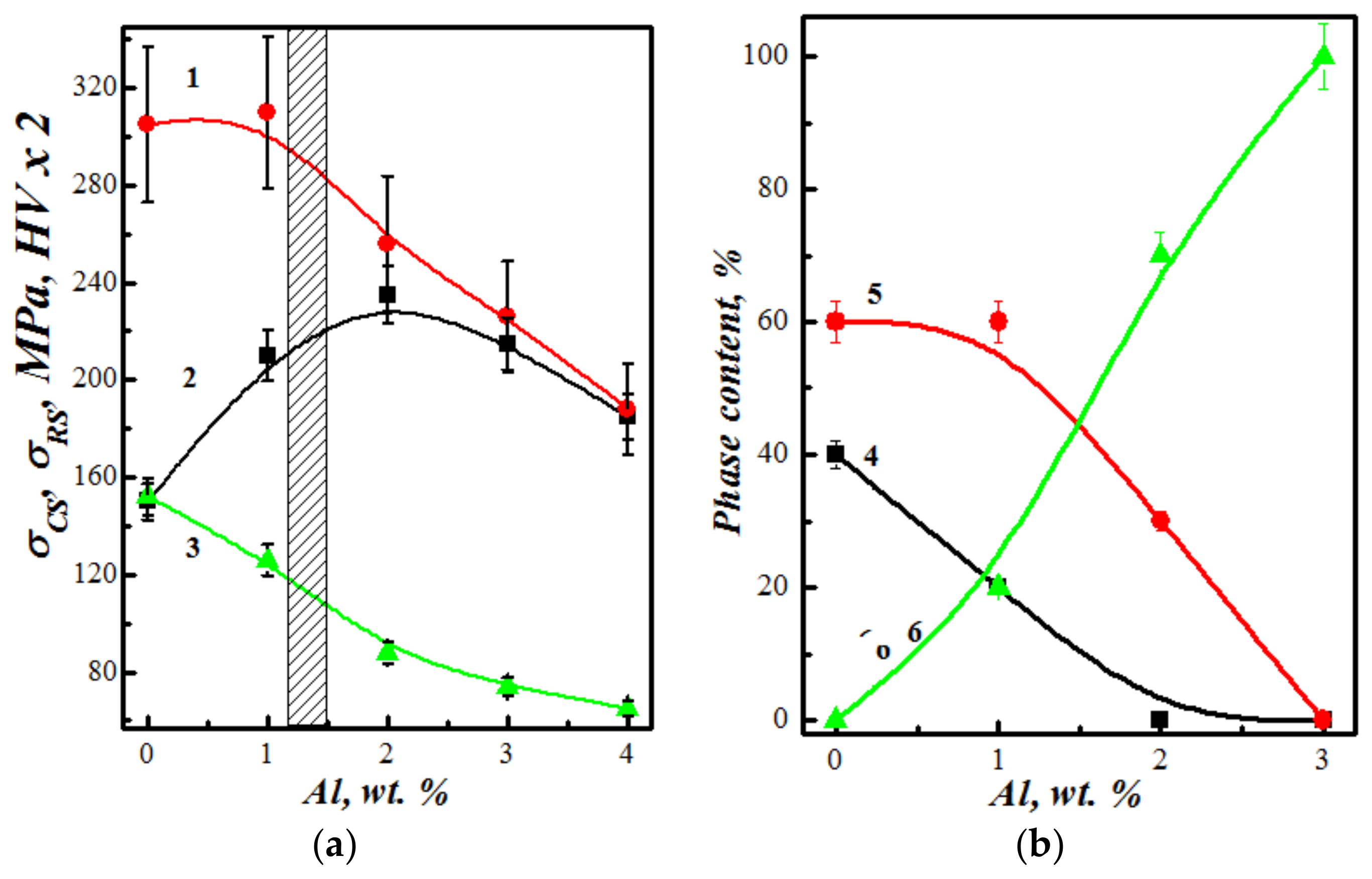
The addition of aluminum to the CW charge first increased the cohesive strength of the coating (Figure 9a). This was associated with aluminothermic reactions in the melt drops during their flight to the substrate and crystallization on it. Due to these reactions, the droplet temperature increased. This contributed to the appearance of a larger number of welding points between them and, as a result, to an increase in the cohesive strength σCS of the coating as a whole. With an increase in the aluminum content in the coating over 2 wt. %, its cohesive strength began to decrease. This is due to the increasing role of aluminum oxides, the film of which prevented droplets from welding together during the formation of the coating and thereby reduced it cohesive strength.
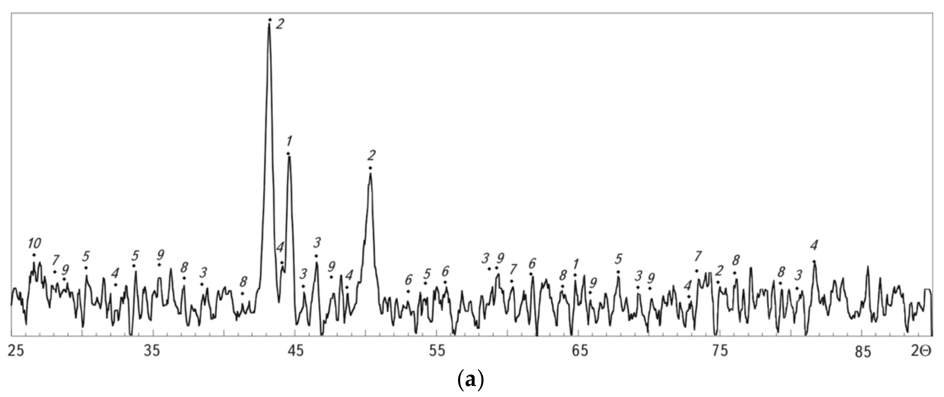
The study of the effect of the aluminum content in the CW charge on the structural-phase composition of coatings (Figure 10) showed that in a coating with an Al content of up to 3 wt. % (at 15 wt. % Al in the CW charge), two matrix phases appear - solid solutions of Cr, Al and C in Feα and Feγ. The structural component Feα was observed in coatings in two forms: in the form of a solid solution of carbon (less than 0.02 wt. % C) in Feα (ferrite with a bcc lattice) or in the form of a supersaturated solid solution of carbon (more than 0.02 wt.% C) in Feα (martensite with a tetragonal bcc lattice). These phases were denoted as Feα(f) and Feα(m), respectively. Moreover, the amount of residual austenite in the coatings decreases with an increase in the aluminum content in the CW charge (Table 3). The residual austenite is not detected in the coating sprayed with CW the charge of which contained 20 wt. % Al (at 4.1 wt. % Al in the coating). In this case, the coating already consists of a solid solution of carbon, aluminum and chromium in Fe and oxides. The distribution of chromium and aluminum in the coating is quite uniform, and only at the boundaries of the lamellae are narrow strips enriched in aluminum and chromium in the form of Al2O3 and Cr2O3 oxide films.
Microhardness of coatings sprayed with CW with 15 wt. % Al in its charge was 400...600 HV. The lower value of this hardness range corresponds to the hardness of austenite, and the upper one to martensite. In the presence of 20 wt. % Al in the CW charge, the micro hardness of coatings from this wire decreases to 200…300 HV. This is due to a change in the phase composition of the coating-martensite and austenite disappear from the coating, and ferrite appears alloyed with aluminum and chromium. This change is due to the action of Al as a strong ferrite-stabilizing element. The combined action of Al and Cr (which is also referred to as a ferrite-stabilizing element) leads to the alloyed ferrite becoming the matrix phase of the coating. The absence of carbides in the coating structure indicates that carbon in the coating is in a free state. This is confirmed by reflections of free carbon on X-ray diffraction patterns.
In coatings of the (FeCrC + Al) system, aluminum and chromium are elements that stabilize ferrite. Under their influence, alloyed ferrite becomes the matrix phase of such coatings. Since ferrite cannot dissolve more than 0.02 wt. % C, then the carbon in the coatings is contained in the free state, which is confirmed by the reflections of free carbon on the diffraction patterns.
Both characteristics, such as the coating hardness HV and the level of tensile residual stresses σRS in it, decrease due to the addition of aluminum to the CW charge (Figure 9a). So, with an increase in the aluminum content from 0 to 4 wt. % in the coating obtained by spraying CW C1.4Cr14Al(0…4), the values of HV decreased by 1.5, and σRS-by 2.5 times. This is due to a change in the phase composition of the coating with an increase in the aluminum content [33,34]. X-ray phase analysis showed an increase in the amount of plastic ferrite in the coating structure with an increase in the aluminum content in it (Figure 9b). This causes a decrease in the hardness of the coating. At the same time, the relaxation of tensile residual stresses in the coating during its crystallization is facilitated due to the presence of a plastic component (ferrite) in its structure. This is due to the simplification of plastic deformation in the lamellae of the coating with a high content of such a plastic component.
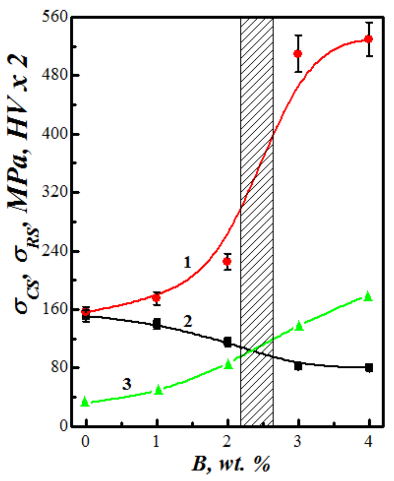
The addition of boron-containing components (ferrochromium-boron, chromium-boron) to the composition of the CW charge leads to a significant increase in the hardness HV of the coating (Figure 11). Thus, an increase in the boron content in the coating from 0 to 4 wt. % leads to an increase in hardness HV (from 320 HV to 1060 HV). However, with an increase in the HV values of the coatings, their cohesive strength σCS decreases (from 160 to 80 MPa) and the residual tensile stresses in them increase.
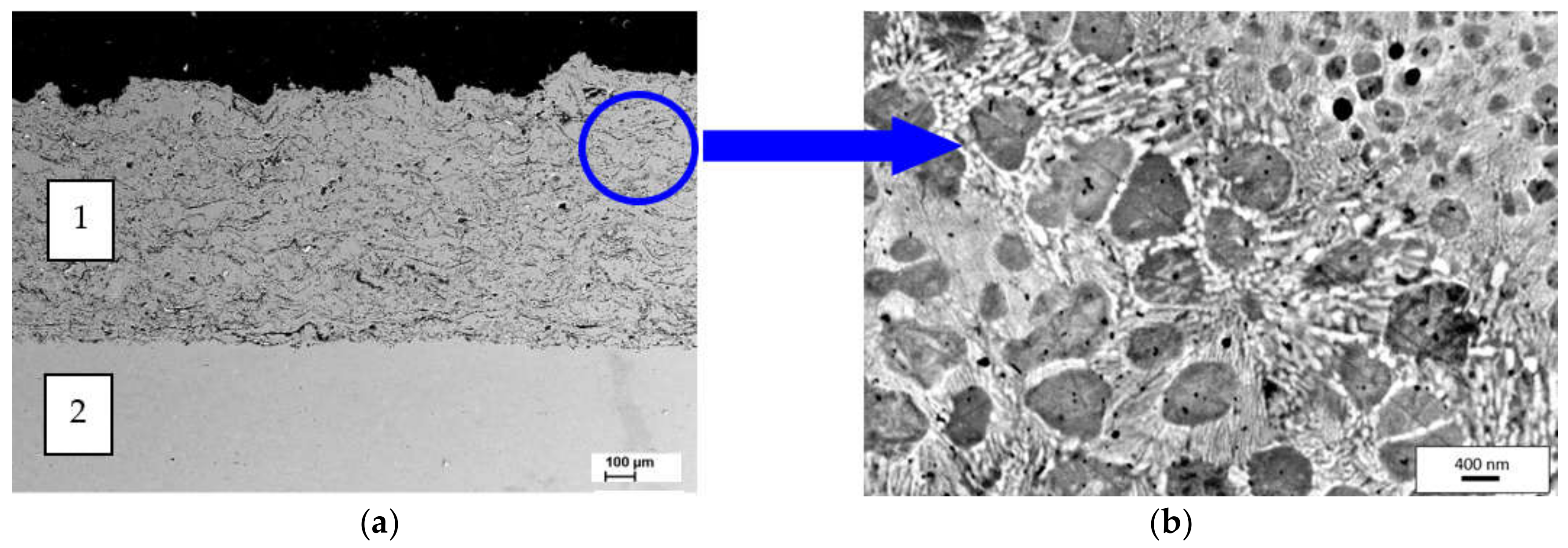
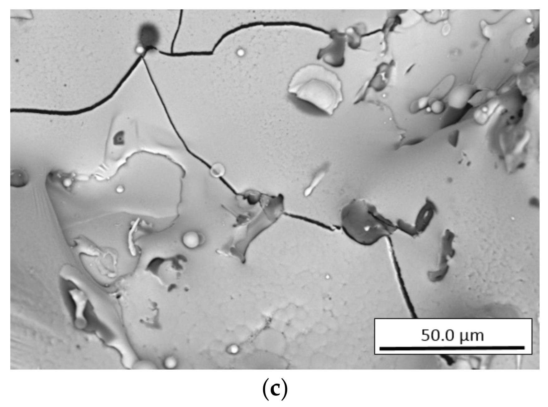
An increase in the hardness of ASCs is associated with the precipitation of particles (finely dispersed FeB and FeCrB borides) smaller than 100 nm in size in their structure (Figure 12). The high hardness of coatings predetermines a special way of relaxation of residual tensile stresses arising as a result of crystallization of CM melt droplets on the part surface. Their relaxation occurs due to the formation of a network of microcracks. As a result, the cohesive strength of the coatings is reduced.
If the matrix phase in the structure of coatings is ferrite, then tempering specimens with a boron-containing coating does not lead to a decrease in residual tensile stresses in them, but, on the contrary, entails their growth. This occurs due to the additional precipitation of boride phases in the structure of the coatings, which leads to a decrease in their volume [35]. As a result, the residual tensile stresses in the coatings increase (Figure 11). If the matrix phase in the structure of the sprayed coating is residual austenite, then its heat treatment (tempering) leads to a significant decrease in the residual tensile stresses in it or even to their transformation into compressive stresses (Table 2). This is due to the transformation of retained austenite into tempered martensite.

4. Conclusions

It is shown that the hardness of electric arc coatings obtained by spraying cored wires increases with an increase in the carbon content in them up to 1 wt. %, and then begins to decrease due to an increase in the content of residual austenite in their structure. The level of residual stresses of the first kind in the coatings increases by a factor of 4 with an increase in the carbon content to 2 wt. %.
The hardness of the coatings and the residual tensile stresses in them increase with a decrease in the aluminum content in them. In this case, the cohesive strength of the coatings increases due to the implementation of aluminothermic reactions in the melting drops of CW during their flight and crystallization on the spraying surfaces. However, with a further increase in the aluminum content in the coatings above 2 wt. %, their cohesive strength decreases.
It is shown that the addition of boron-containing components (ferrochrome-boron, chromo-boron) to the composition of the CW charge leads to a significant increase in the hardness of the coatings. However, this increases the residual tensile stresses in the coatings and reduces their cohesive strength.
The mechanical characteristics of ASCs obtained by CS deposition depend on their phase composition. With an increase in the content of residual austenite in the structure of the coatings, their cohesive strength increases, but at the same time, the residual tensile stresses in them increase significantly. With an increase in the content of ferrite and martensite in the coating structure, the residual tensile stresses in them decrease.
Heat treatment (tempering) of coatings with a predominance of residual austenite in their structure reduces residual tensile stresses or even transforms them into compressive stresses. Tempering coatings with a ferritic structure lead to an increase in residual stresses in them due to the precipitation of finely dispersed carbides or borides.

Author Contributions

This research was conceptualized by M.S.; the experiments (investigation) were conducted by M.S., V.H., T.S., O.S., P.M., O.P. and P.S.; and the results (formal analysis) were analyzed and discussed by M.S., V.H., T.S., O.S. and P.M. The manuscript was written (original draft) by M.S. and O.S., and reviewed (writing and editing) by O.P. and P.S. All authors have read and agreed to the published version of the manuscript.

Funding

The research described in this paper was financially supported by the Target research program of the National Academy of Sciences of Ukraine, “Scientific and technical problems of condition monitoring, evaluation and extension of the service life of structures, equipment and structures of long-term operation” (Program Resource-3), approved by the resolution of the Presidium of the NAS of Ukraine dated 09 of December 2020 № 269, and the order of the Presidium of the NAS of Ukraine dated 29 of March 2021 № 182. This support is highly appreciated by the authors.

Institutional Review Board Statement

Not applicable.

Informed Consent Statement

Not applicable.

Data Availability Statement

The data presented in this study are available upon request from the corresponding author.

Conflicts of Interest

The authors declare no conflict of interest.

References

  1. Goharian, A.; Bin Abdullah, M.R. Plasma spraying process for osseoconductive surface engineering. In Osseoconductive Surface Engineering for Orthopedic Implants; Elsevier: Amsterdam, The Netherlands, 2021; pp. 19–53. [Google Scholar] [CrossRef]
  2. Ruys, A.J.; Sutton, B.A. Metal-ceramic functionally graded materials (FGMs). In Metal-Reinforced Ceramics; Elsevier Series on Advanced Ceramic Materials; Elsevier: Amsterdam, The Netherlands, 2021; pp. 327–359. [Google Scholar] [CrossRef]
  3. Bakan, E.; Mack, D.E.; Mauer, G.; Vaßen, R.; Lamon, J.; Padture, N.P. High-temperature materials for power generation in gas turbines. In Advanced Ceramics for Energy Conversion and Storage; Elsevier: Amsterdam, The Netherlands, 2020; pp. 3–62. [Google Scholar] [CrossRef]
  4. Student, М.М.; Pokhmurs’ka, H.V.; Zadorozhna, K.R. Structure and wear resistance of VC–FeCr and VC–FeCrCo coatings obtained by supersonic flame spraying. Mater. Sci. 2018, 54, 22–29. [Google Scholar] [CrossRef]
  5. Takalapally, S.; Kumar, S.; Pusuluri, S.H.; Palle, M. A critical review on surface coatings for engineering materials. Int. J. Mech. Eng. Technol. 2016, 7, 80–85. [Google Scholar]
  6. Stupnyts’kyi, T.R.; Student, M.M.; Pokhmurs’ka, H.V.; Hvozdets’kyi, V.M. Optimization of the chromium content of powder wires of the fe–cr–c and fe–cr–b systems according to the corrosion resistance of electric-arc coatings. Mater. Sci. 2016, 52, 165–172. [Google Scholar] [CrossRef]
  7. Student, М.М.; Shmyrko, V.V.; Klapkiv, М.D.; Lyasota, І.M.; Dobrovol’ska, L.N. Evaluation of the mechanical properties of combined metal-oxide-ceramic layers on aluminum alloys. Mater. Sci. 2014, 50, 290–295. [Google Scholar] [CrossRef]
  8. Zhang, X.; Wang, Z.; Lin, J. High temperature oxidation behavior of arc-sprayed FeCrBAlMo coating. J. Adv. Oxid. Technol. 2016, 19, 105–112. [Google Scholar] [CrossRef]
  9. Kant, S.; Kumar, M.; Chawla, V.; Singh, S. Study of high temperature oxidation behavior of wire arc sprayed coatings. Mater. Today Proc. 2020, 21, 1741–1748. [Google Scholar] [CrossRef]
  10. Kumar, S.; Kumar, M.; Handa, A. Comparative study of high temperature oxidation behavior and mechanical properties of wire arc sprayed NiCr and NiAl coatings. Eng. Fail. Anal. 2019, 106, 104173. [Google Scholar] [CrossRef]
  11. Zhuang, X.; Tan, Y.; You, X.; Li, P.; Zhao, L.; Cui, C.; Zhang, H.; Cui, H. High temperature oxidation behavior and mechanism of a new Ni-Co-based superalloy. Vacuum 2021, 189, 110219. [Google Scholar] [CrossRef]
  12. Li, Y.; Liang, T.; Ao, R.; Zhao, H.; Chen, X.; Zeng, J. Oxidation resistance of iron-based coatings by supersonic arc spraying at high temperature. Surf. Coat. Technol. 2018, 347, 99–112. [Google Scholar] [CrossRef]
  13. Cheng, J.; Wu, Y.; Chen, L.; Hong, S.; Qiao, L.; Wei, Z. Hot corrosion behavior and mechanism of high-velocity arc-sprayed Ni-Cr alloy coatings. J. Therm. Spray Technol. 2019, 28, 1263–1274. [Google Scholar] [CrossRef]
  14. Pokhmurs’kyi, V.; Student, M.; Formanek, B.; Serivka, V.; Dz’oba, Y.; Dovhunyk, V.; Sydorak, I. Heat resistance of electric arc coatings made of Fe-Cr-B-Al powder wire. Mater. Sci. 2003, 39, 829–834. [Google Scholar] [CrossRef]
  15. Wielage, B.; Pokhmurska, H.; Student, M.; Gvozdeckii, V.; Stupnyckyj, T.; Pokhmurskii, V. Iron-based coatings arc-sprayed with cored wires for applications at elevated temperatures. Surf. Coat. Technol. 2013, 220, 27–35. [Google Scholar] [CrossRef]
  16. Szymański, K.; Hernas, A.; Moskal, G.; Myalska, H. Thermally sprayed coatings resistant to erosion and corrosion for power plant boilers—A review. Surf. Coat. Technol. 2015, 268, 153–164. [Google Scholar] [CrossRef]
  17. Student, M.M.; Pokhmurs’ka, H.V.; Hvozdets’kyi, V.V.; Holovchuk, M.Y.; Romaniv, M.S. Effect of high-temperature corrosion on the gas-abrasive resistance of electric-arc coatings. Mater. Sci. 2009, 45, 481–489. [Google Scholar] [CrossRef]
  18. Student, M.M.; Dovhunyk, V.M.; Sydorak, I.I.; Pokhmurs’ka, H.V.; Yas’kiv, O.I. Effect of friction on phase transitions in the surface layers of FeCrB + Al gas-thermal coatings. Mater. Sci. 2000, 36, 607–611. [Google Scholar] [CrossRef]
  19. Brezinová, J.; Guzanová, A.; Draganovská, D.; Maruschak, P.O.; Landová, M. Study of selected properties of thermally sprayed coatings containing WC and WB hard particles. Acta Mech. Autom. 2016, 10, 296–299. [Google Scholar] [CrossRef] [Green Version]
  20. Tillmann, W.; Hagen, L.; Kokalj, D. Spray characteristics and tribo-mechanical properties of high-velocity arc-sprayed WC-W2C iron-based coatings. J. Therm. Spray Technol. 2017, 26, 1685–1700. [Google Scholar] [CrossRef]
  21. Pokhmurs’ka, H.V.; Dovhunyk, V.M.; Student, M.M. Wear resistance of laser-modified arc-sprayed coatings made of FMI-2 powder wires. Mater. Sci. 2003, 39, 533–538. [Google Scholar] [CrossRef]
  22. Student, M.M.; Markovych, S.I.; Gvodetskyi, V.M.; Kalahan, O.S.; Yuskiv, V.M. Abrasive wear resistance and tribological characteristics of composite coatings. Phys.-Chem. Mech. Mater. 2022, 1, 83–90. [Google Scholar]
  23. Daram, P.; Munroe, P.; Banjongprasert, C. Microstructural evolution and nanoindentation of NiCrMoAl alloy coating deposited by arc spraying. Surf. Coat. Technol. 2020, 391, 125565. [Google Scholar] [CrossRef]
  24. Horner, A.L.; Hall, A.C.; McCloskey, J.F. The effect of process parameters on twin wire arc spray pattern shape. Coatings 2015, 5, 115–123. [Google Scholar] [CrossRef] [Green Version]
  25. Ndiithi, N.J.; Kang, M.; Zhu, J.; Lin, J.; Nyambura, S.M.; Liu, Y.; Huang, F. Microstructural and corrosion behavior of high velocity arc sprayed FeCrAl/Al composite coating on Q235 steel substrate. Coatings 2019, 9, 542. [Google Scholar] [CrossRef] [Green Version]
  26. Yao, H.; Zhou, Z.; Wang, Y.; He, D.; Bobzin, K.; Zhao, L.; Öte, M.; Königstein, T. Microstructure and properties of FeCrB alloy coatings prepared by wire-arc spraying. J. Therm. Spray Technol. 2017, 26, 483–491. [Google Scholar] [CrossRef]
  27. Student, M.; Gvozdetsky, V.; Student, O.; Prentkovskis, O.; Maruschak, P.; Olenyuk, O.; Titova, L. The effect of increasing the air flow pressure on the properties of coatings during the arc spraying of cored wires. Stroj. Cas. 2019, 69, 133–146. [Google Scholar] [CrossRef] [Green Version]
  28. Pokhmurska, H.; Student, M.; Paczkowski, G.; Holovchuk, M.; Chumalo, H.; Hvozdetskyi, V.; Schuberth, S. Influence of diameter of the cored wires on abrasive wear resistance of arc sprayed coatings. In IOP Conference Series: Materials Science and Engineering; IOP Publishing: Bristol, UK, 2021; Volume 1147, p. 012033. [Google Scholar] [CrossRef]
  29. Kraus, W.; Nolze, G. POWDER CELL—A program for the representation and manipulation of crystal structures and calculation of the resulting X-ray powder patterns. J. Appl. Cryst. 1996, 29, 301–303. [Google Scholar] [CrossRef]
  30. Birger, I.A. Methods for determining residual stresses in thin-walled pipes. Zavod. Lab. 1962, 9, 1112–1117. (In Russian) [Google Scholar]
  31. Babichev, M.A. Methods for Determining Internal Stresses in Machine Parts; Publishing House of the Academy of Sciences of the USSR: Moscow, Russia, 1955; 132p. (In Russian) [Google Scholar]
  32. Student, M.; Dzioba, Y.; Hvozdets’kyi, V.; Pokhmurs’ka, H.; Wielage, B.; Grund, T. High-temperature corrosion of electric-arc coatings sprayed from powder core wires based on the Fe-Cr-B-Al system. Mater. Sci. 2008, 44, 693–699. [Google Scholar] [CrossRef]
  33. Geng, Y.; Panchenko, I.; Chen, X.; Ivanov, Y.; Konovalov, S. Investigation of microstructure and fracture mechanism of al-5.0 mg alloys fabricated by wire arc additive manufacturing. J. Mater. Eng. Perform. 2021, 30, 7406–7416. [Google Scholar] [CrossRef]
  34. Geng, Y.; Panchenko, I.; Chen, X.; Ivanov, Y.; Konovalov, S. Wire arc additive manufacturing Al-5.0 Mg alloy: Microstructures and phase composition. Mater. Charact. 2022, 187, 111875. [Google Scholar] [CrossRef]
  35. Brezinová, J.; Guzanová, A.; Tkáčová, J.; Brezina, J.; Ľachová, K.; Draganovská, D.; Pastorek, F.; Maruschak, P.; Prentkovskis, O. High velocity oxygen liquid-fuel (HVOLF) spraying of WC-based coatings for transport industrial applications. Metals 2020, 10, 1675. [Google Scholar] [CrossRef]
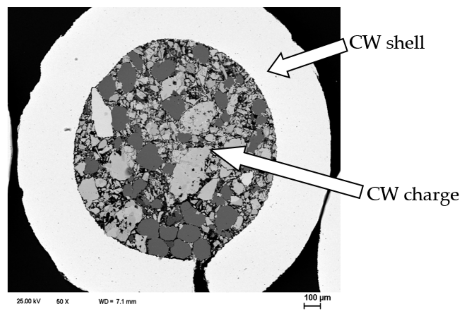
Figure 1. Cross section of cored wire.
Coatings 12 00925 g001
Figure 2. Scheme (a) and specimens (b,c) for determining residual stresses in coatings.
Coatings 12 00925 g002
Figure 3. Scheme of the device for measuring internal stresses in the coating directly during CW spraying to the surface of the ring: 1—ring with a longitudinal section (specimen); 2—rods for fixing the strain-gauge sensor; 3—strain-gauge sensor to measure of displacement of the edges of the longitudinal section of ring; 4—screen to protect the strain-gauge sensor from melt drops of CW; and 5—electric wires from the strain-gauge sensor to the measuring device.
Coatings 12 00925 g003
Figure 4. Schematic diagram of the experimental measurement of stresses in the coating during its spraying: 1—ring with a longitudinal section (specimen); 2—electrometallizer; 3—oating; 4—extension rods for fixing the beams of strain-gauge sensor; 5—beam; 6—load cell; 7—strain-gauge sensor body; 8—electric motor; 9—the central rod fixed on the ring, around which the ring rotated in the process of spraying; and 10—device for registering the relative displacement of the ring ends.
Coatings 12 00925 g004
Figure 5. Scheme of the device for applying ASC to the surface of the assembled specimen and the specimen, released from the mandrel, ready for stretching until the coating breaks and determining its cohesive strength (a): 1—two parts of the specimen; 2—bolt; 3—guide washers; 4—spring; 5—nut; 6—coating; 7—thread for tensile grips; and (b) failed specimens after tests for cohesive strength.
Coatings 12 00925 g005
Figure 6. X-ray diffraction patterns of arc coatings obtained with CW: (a) No. 1: 1—Feα(m); 2—(Fe, Cr)3C; Traces: 3—(Fe, Cr)23C6; 4—(Fe, Cr)7C3; 5—Fe2O3, and 6—Al2O3; (b) No. 2: 1—Feα(m); 2—Feγ (residual austenite); 3—FeCr; Traces: 4—(Fe, Cr)3C6; 5—CaF2; 6—FeO; 7—Cr2O3; and 8—Al2O3; (c) No. 3, and (d) No. 5. The CW numbers correspond to those given in Table 1.
Coatings 12 00925 g006aCoatings 12 00925 g006b
Figure 7. Mechanical properties: (a) Hardness HV (1), cohesive strength σCS (2) and residual stresses σRS (3) and (b) relative amounts of martensite (4), residual austenite (5), and ferrite (6) in coatings versus carbon content C in ASCs deposited by spraying of CW C(0.2…1.4)Cr14. Hatching highlights, the zone of optimal carbon content in the coating to provide the best combination of the analyzed characteristics.
Coatings 12 00925 g007
Figure 8. Effect of tempering temperature T on residual tensile stresses σRS in coatings obtained by spraying CWs with different charge compositions: C1.4Cr14B3NiTi2Al (1), C0.2Cr18B3Ti2Al (2), C1.4Cr14Ni2Ti2Al (3).
Coatings 12 00925 g008
Figure 9. Mechanical properties: (a) Hardness HV (1), cohesive strength σCS (2) and residual stresses σRS (3) and (b) relative amounts of martensite (4), residual austenite (5), and ferrite (6) in coatings versus aluminum content Al in ASCs deposited by spraying of CW C1.4Cr14 Al(0…4). Hatching highlights the zone of optimal aluminum content in the coating to provide the best combination of the analyzed characteristics.
Coatings 12 00925 g009
Figure 10. X-ray diffraction patterns of arc coatings of the system (FeCrC + Al) sprayed with CW, the charge of which contained different amounts of aluminum, wt. %: (a) 2: 5, 1—Feα(m); 2—Feγ (residual austenite); Traces: 3—Fe3C; 4—Cr7C3; 5—Cr2O3; 6—Fe3O4; 7—FeO; 8—CrN; 9—AlN; and 10—graphite; (b) 5: 1—Feα(f) + Feα(m); 2—Feγ (residual austenite); Traces: 3—Fe3C; 4—Fe3Al; 5—Al2O3; 6—Cr2O3; 7—Fe2O3; 8—Fe3O4; 9—CrN; 10—AlN; and 11—graphite; (c) 15: 1—Feα(f) + Feα(m); 2—Feγ (residual austenite); Traces: 3—Fe3C; 4—Fe3Al; 5—Al2O3; 6—Cr2O3; 7—Fe2O3; 8—Fe3O4; 9—CrN; 10—AlN; and 11—graphite and (d) 20: 1—Feα(f) + Feα(m); Traces: 2—Cr; 3—FeCr; 4—CrN; 5—Fe2P; 6—Al2O3; 7—Cr2O3; and 8—Fe2O3.
Coatings 12 00925 g010aCoatings 12 00925 g010b
Figure 11. Hardness HV (1), cohesive strength σCS (2) and residual stresses σRS (3) in coatings versus boron content B in ASCs deposited by spraying of CW B(0...4) Ni4Ti2Al2. Hatching highlights the zone of optimal boron content in the coating to provide the best combination of the analyzed characteristics.
Coatings 12 00925 g011
Figure 12. The microstructure of the coating in its cross section after heat treatment at 550 °C at low (a) and high magnifications with precipitation of FeB and FeCrB borides as a dark inclusions in the coating structure (b) and microcracks between inclusions on the surface of the sprayed coating (c), due to which tensile stresses are relaxed in an arc coating obtained by spraying CW C1.4Cr14B3NiTi2Al. 1—coating and 2—steel base.
Coatings 12 00925 g012aCoatings 12 00925 g012b
Table 1. Influence of the CW charge composition on the phase composition of the obtained coatings.
NoChemical Composition of the CW Charge, wt. %Content of Cr and C in the Coating, wt. %Phase Composition of the CoatingPhase Ratio
1FeCr (with 2 wt. % C)
Fe
70
30
C
Cr
Fe
0.2
14.0
Rest
Feα(m)/Feγ
(Fe,Cr)3C;
8/1
Traces
2FeCr (with 8 wt. % C)
Fe
70
30
C
Cr
Fe
0.5
14.1
Rest
Feα(m)/Feγ
(Fe,Cr)3C6
Fe2O3, Fe3O4
3/1
Traces
Traces
3FeCr (with 8 wt. % C)
C(graphite)
Fe
60
5
35
C
Cr
Fe
1.0
13.9
Rest
Feα(m)/Feγ
TiO2, Al2O3
FeO, Fe2O3,
Fe3O4
1/1
Traces
Traces
Traces
4FeCr (with 8 wt. % C)
C (graphite)
Fe
60
10
30
C
Cr
Fe
1.5
13.9
Rest
Feα(m)/Feγ
FeO, Fe2O3,
Fe3O4
2/3
Traces Traces
5FeCr (with 8 wt. % C)
C (graphite)
Fe
60
10
30
C
Cr
Fe
2.0
14.0
Rest
Feα(m)/Feγ
Fe2O3,
Fe3O4
1/3
Traces
Traces
Table 2. Mechanical characteristics of ASCs deposited by spraying of CWs with different charge compositions.
CW TypeAfter SprayingAfter 2 h Tempering at 550 °CPhase Composition of Coatings
HVσCS,
MPa
σRS,
MPa
HVσCS,
MPa
σRS,
MPa
C1.4Cr14Ni2500–60029370450–550160−42Feγ; Feα(m); traces
(FeCr)23C6,(FeCr)2О3
C1.4Cr14Ni2Ti2Al450–55025071450–50018012Feγ; Feα(m); traces (FeCr)23C6,(FeAlТі)хОу
C1.4Cr14B3NiTi2Al700–10007057600–9507518Feγ; Feα(m); traces
(FeCr)2В (FeAlВ)хОу
C0.2Cr24B3MnSi2Al900–105011050800–88011050Feα(m); (FeCr)2B
C0.2Cr18B3Ni2Ti2850–95020090800–90018882(FeCr)2В, (FeAlТі)хОу
C0.2Cr18B3Ti2Al700–100015095700–900145120(FeCr)2В, (FeAlТі)хОу
Table 3. Effect of the Al content in the CW charge of the Fe–Cr–C–Al system on the phase composition of sprayed coatings.
NoChemical Composition
of the CW Charge, wt. %
Chemical Composition
of the Coatings, wt. %
Phase Composition of the CoatingPhase Ratio
1FeCr (with 8 wt. % C)
Fe
Al
70
28
2
C
Cr
Al
Fe
0.9
14.2
0.4
Rest
Feα(m)/ Feγ
Fe3C
Fe2O3, Fe3O4
3/1
Traces
Traces
2FeCr (with 8 wt. % C)
Fe
C (graphite)
Al
70
20
5
5
C
Cr
Al
Fe
1.0
13.5
1.0
Rest
Feα(f) + Feα(m)/Feγ
Fe3C
FeO, Fe2O3, Fe3O4
1.4/1
Traces
Traces
3FeCr (with 8 wt. % C)
Fe
C (graphite)
Al
60
25
5
10
C
Cr
Al
Fe
0.9
14.0
2.0
Rest
Feα(f) + Feα(m)/Feγ
Fe3C
FeO, Fe2O3,
Fe3O4
1.4/1
Traces
Traces
4FeCr (with 8 wt. % C)
Fe
C (graphite)
AI
60
20
5
15
C
Cr
AI
Fe
0.95
14.1
3.0
Rest
Feα(f) + Feα(m)/Feγ
Fe3C
FeO, Fe2O3,
Fe3O4
2.2/1
Traces
Traces
5FeCr (with 8 wt. % C)
Fe
C (graphite)
Al
60
15
5
20
C
Cr
Al
Fe
0.9
14.0
4.1
Rest
Feα(f) + Feα(m)/Feγ
Fe3C
FeO, Fe2O3,
Fe3O4
9/1
Traces
Traces
Traces
Publisher’s Note: MDPI stays neutral with regard to jurisdictional claims in published maps and institutional affiliations.