Article

The Effect of an Ultrasonic Field on the Microstructure and Tribological Behavior of ZrB2/ZrC+Ni60A/WC Composite Coating Applied by Laser Cladding

1
School of Mechanical Engineering, Xijing University, Xi’an 710123, China
2
Department of Engineering, Islamic Azad University Saveh Branch, Saveh 1631-676757, Iran
3
Department of Advanced Materials and New Energies, Iranian Research Organization for Science and Technology (IROST), Tehran 33535111, Iran
4
Department of Engineering, Payame Noor University (PNU), Tehran P.O. Box 19395-4697, Iran
5
Metallurgy Expert and Curriculum Developer in Technical and Vocational Education Textbooks Publication-Office, Organization of Educational Research and Planning (OERP), Ministry of Education, Tehran P.O. Box 15847-47359, Iran
*
Authors to whom correspondence should be addressed.
Coatings 2023, 13(11), 1928; https://doi.org/10.3390/coatings13111928
Submission received: 3 October 2023 / Revised: 3 November 2023 / Accepted: 9 November 2023 / Published: 11 November 2023
(This article belongs to the Special Issue Additive Manufacturing of Metallic Components for Hard Coatings)

Abstract

:
Ni60A/WC composite coating reinforced with ZrB2/ZrC was layered on GTD-111 superalloy by laser cladding. The effect of an ultrasonic field on coating formation, microstructure, microhardness, and wear was investigated and analyzed. The results showed that the resulting coating had pores and microcracks, which were removed when using an ultrasonic field. Ultrasonic fields increased the heat input and increased the dimensions of the coating pool by creating a cavitation effect. The dendrites of the coating microstructure were mainly composed of Zr(B, C) and ZrC blocks and small α-Zr dendrites. The mechanical vibrations resulting from the application of ultrasonic fields caused the crushing of the growing dendrites, and as a result, the grains and dendrites crumbled. By decreasing the grain size, the average hardness increases from 312 HV for coating without an ultrasonic field to 617 HV for coating with 300 W ultrasonic power. The results of the wear test also showed that the sample coated with 300 W of ultrasonic power, with a coefficient of friction of 0.41 and scar wear of 6.8 µm, has the highest wear resistance due to the removal of porosity and the presence of equiaxed grains on the top and bottom of the clad zone.

1. Introduction

Gas turbines, which convert the internal energy of hot and compressed gases into mechanical energy in the power plant and aerospace industries, experience critical conditions during operation [1]. In case of not using the appropriate material and coating, damages such as creep, corrosion, oxidation, fatigue, and wear will cause the turbine to malfunction and cause irreparable damage [2]. Nickel-based superalloys have ideal properties in critical working conditions due to their multiphase and complex microstructure, which includes γ′ phase, γ–γ′ eutectic, Cr–Mo-rich borides, Ni–Zr intermetallics, and Cr–Ti–Ta-rich carbides [3]. Among these materials, GTD-111 superalloy is used as the first-row blades of gas turbines due to its ideal chemical composition [4]. However, using this material without a coating is strictly not recommended. Taheri et al. [2] reported that the GT 13-E2 General Electric gas turbine blade made of GTD-111 superalloy suffered microstructural damage and failure after 10,000 h of operation at a temperature of 850 °C.
In recent years, researchers have proposed various techniques to modify the surface of gas turbine blades. Among these methods are aluminide coatings [5], thermal barriers [6], arc plasma spray [7], sol-gel [8], and laser cladding [9,10]. However, research results have shown that some of the above technologies have limitations, such as low deposition efficiency, poor substrate and coating bonding, and poor process stability. Szczepankowski et al. [11] reported the gradual oxidation and depletion of Al, as well as the effects of environmental particles, as the reason for reducing the efficiency of thermal barrier coatings. Wang et al. [12] introduced the formation of NiMoO4 and MoO3 lubricants in NiCoCrAlY–Cr2O3–AgMo coating sprayed on GH4169 superalloy as a factor in reducing the coefficient of friction (COF) and increasing wear resistance. Finally, the non-adherence of the coating to the substrate was attributed to the increase in COF and decrease in wear resistance. In general, the literature states that the reduction of coating adhesion to the substrate is the most important factor in reducing the wear resistance of coatings applied on superalloys [5,13].
Laser cladding technology has become an ideal method for coating gas turbine blades due to its advantages, such as creating a strong bond between the coating and the substrate, low heat input, and high flexibility in changing parameters [9,10,14]. Refinement of the grains during laser cladding and uniform distribution of reinforcing phases due to the Marangoni force results in the creation of equiaxed grains that are resistant to wear and corrosion at high temperatures [15]. By reviewing the literature, it has been determined that the coatings applied by the laser cladding method show better tribological behavior than other coatings due to the advantages mentioned, including proper adhesion to the substrate [16]. The nickel-coated graphene nanoplatelets (GNP) and IN625 powder were successfully coated by laser cladding after ball milling. The processing of the resulting coating by Deng et al. [17] showed that NbC by increasing the coating hardness, GNP by lowering the COF, and the solidification process caused by laser cladding by creating refined grains significantly increase the wear resistance of the coating. Li et al. [18] increased the wear and corrosion resistance of the pneumatic transmission pipe used in the coal industry using the Ni alloy–WC composite coating using laser cladding. Their report showed that expansion of equiaxed grains in the coating, reduction in the temperature gradient, and increase in hardness caused by the presence of WC are the most important reasons for resistance to wear and corrosion. After applying yttrium–aluminum garnet/yttria-stabilized zirconia coating on IN738 superalloy by atmospheric plasma spraying, Sheng et al. [19] modified the outer layer through the laser-modified method. The results of their work showed that in addition to increasing wear resistance, oxygen penetration during high-temperature oxidation to the substrate is reduced, and as a result, the rate of thermally grown oxide is reduced, and oxidation resistance is increased.
Metallic nickel-based materials, including Ni60A, are among the materials that are used as coating materials [20]. To increase the efficiency of the coating, various ceramic materials such as ZrB2 and ZrC have been recommended as reinforcements in Ni60A due to their excellent thermal stability, corrosion, and wear resistance [21]. To reduce the probability of the formation of Ni–Zr intermetallic compounds, adding WC is recommended [22]. Because WC, in addition to the excellent wear properties it creates in the coating, with decomposition during laser cladding, the possibility of forming more Ni–Zr intermetallic compounds in the coating is reduced, and due to the in situ reaction between C and Zr, and the result of creating ZrC, the property and efficiency of the coating increases [23]. By adding WC to FeCoNiCuAl metal coating, Zhao et al. [24] showed that the addition of WC, in addition to fine-grained microstructure, greatly increases the wear resistance by decomposing into WC, W2C, and Co4W2C during laser cladding. By applying an ultrasonic field during laser cladding, Huang et al. [25] increased the wear resistance of Ni60/WC–TiO2 + La2O3 composite coating by reducing porosity, reducing dilution, increasing hardness, and refining grains. The creation of the cavitation effect and crushing of dendrites was reported to be the most important cause of the above reasons.
The aim of this work is to improve the tribological behavior of GTD-111 superalloy by applying ZrB2/ZrC-Ni60A/WC coating by laser cladding. To distribute the reinforcements uniformly and help the in situ reaction between the reinforcements, ultrasonic mechanical vibrations in different powers of 100 W~400 W were used simultaneously with laser cladding. The effect of reinforcements and ultrasonic field on the formation and decomposition of phases was analyzed by XRD. The formation of morphology of grains and dendrites at the top and bottom of the coating and also the formation of porosity were investigated by scanning electron microscope (SEM). Finally, the hardness and tribological behavior of the coating were investigated and analyzed by the pin-on-disc wear test.

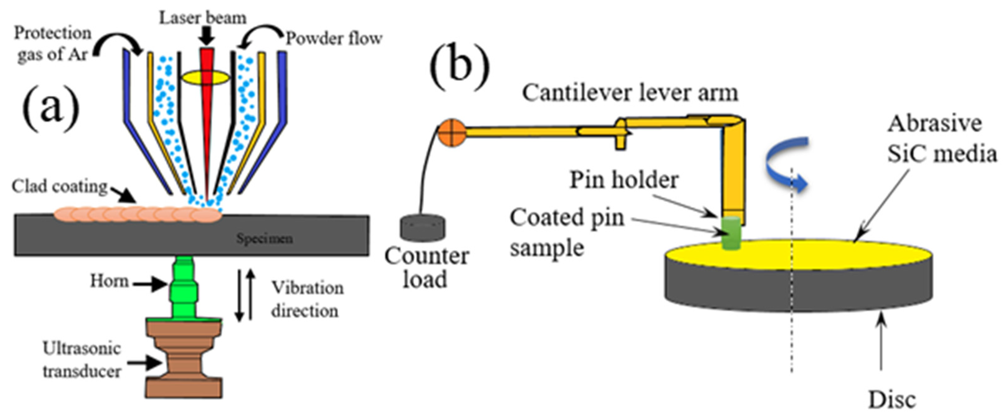
2. Materials and Methods

GTD-111 superalloy sheet with dimensions of 80 × 80 × 3 mm3 and chemical composition presented in Table 1 was chosen as the substrate. The coating powder consisted of two components; the first component consisted of NI60A + 25% WC powder, which was mixed in a ball mill for 3 h before coating until a uniform powder with a particle size of 40–100 µm was obtained. The reinforcing powder was a combination of ZrB2–ZrC ceramic particles with an approximate size of 10–40 µm, which was added to the composition of NI60A + 25% WC at the rate of 15%. Figure 1a–c shows the morphology of the above powdery compounds.
An IQL-10 pulsed Nd:YAG laser device with a maximum output power of 700 W and a scan path controller by the robot was used. The parameters used for laser cladding were selected based on trial and error and previous studies [24,26], presented in Table 2. To influence the mechanical vibrations during laser cladding, an ultrasonic vibration device was used with the parameters determined in Table 2. The schematic of the coating process is shown in Figure 2a.
After coating, the specimens were cut perpendicular to the coating by a wire cutter. After metallographic steps, they were etched by HF:HCl:HNO3 = 1:3:6 solution and prepared for microstructural investigations. A scanning electron microscope (SEM; S-3400N, Hitachi, Ibaraki, Japan) equipped with energy-dispersive X-ray spectroscopy (EDS) and electron back-scattered diffraction (EBSD) was used for microstructural investigations at different stages. XRD analyzer (Shimadzu XRD-6100 Kyoto, Japan) was used to determine phase compounds and the role of ultrasonic vibrations in their formation. A Vickers microhardness device (HpV, Huayin, China, HVS-1000) was used to determine the hardness of the substrate and coating with a constant force of 2 N and a holding time of 10 s. To investigate the tribological behavior of the coating and the substrate, the pin-on-disc method was used. The wear test parameters were: sliding speed of 35 cm/s, applied force of 40 N, sliding wear time of 17 min, and pin rotating speed of 25 rpm. The Si3N4 ball (5 mm in diameter) was used as a grinding ball (Figure 2b).

3. Results

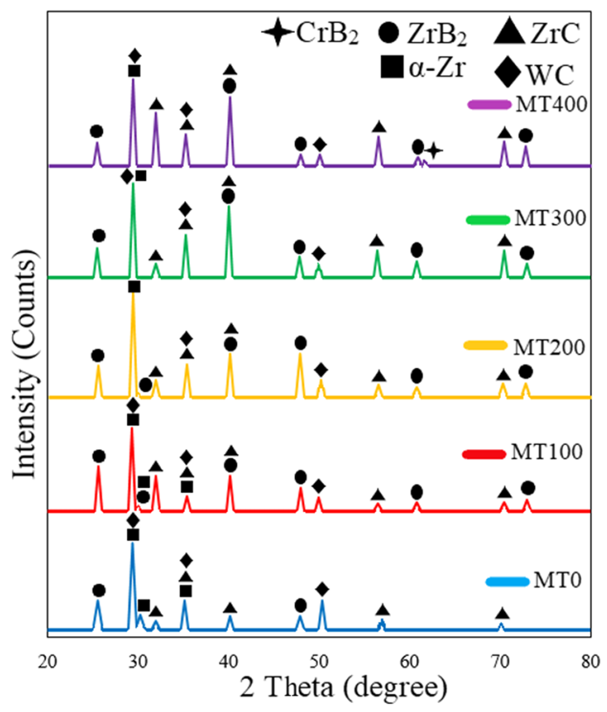
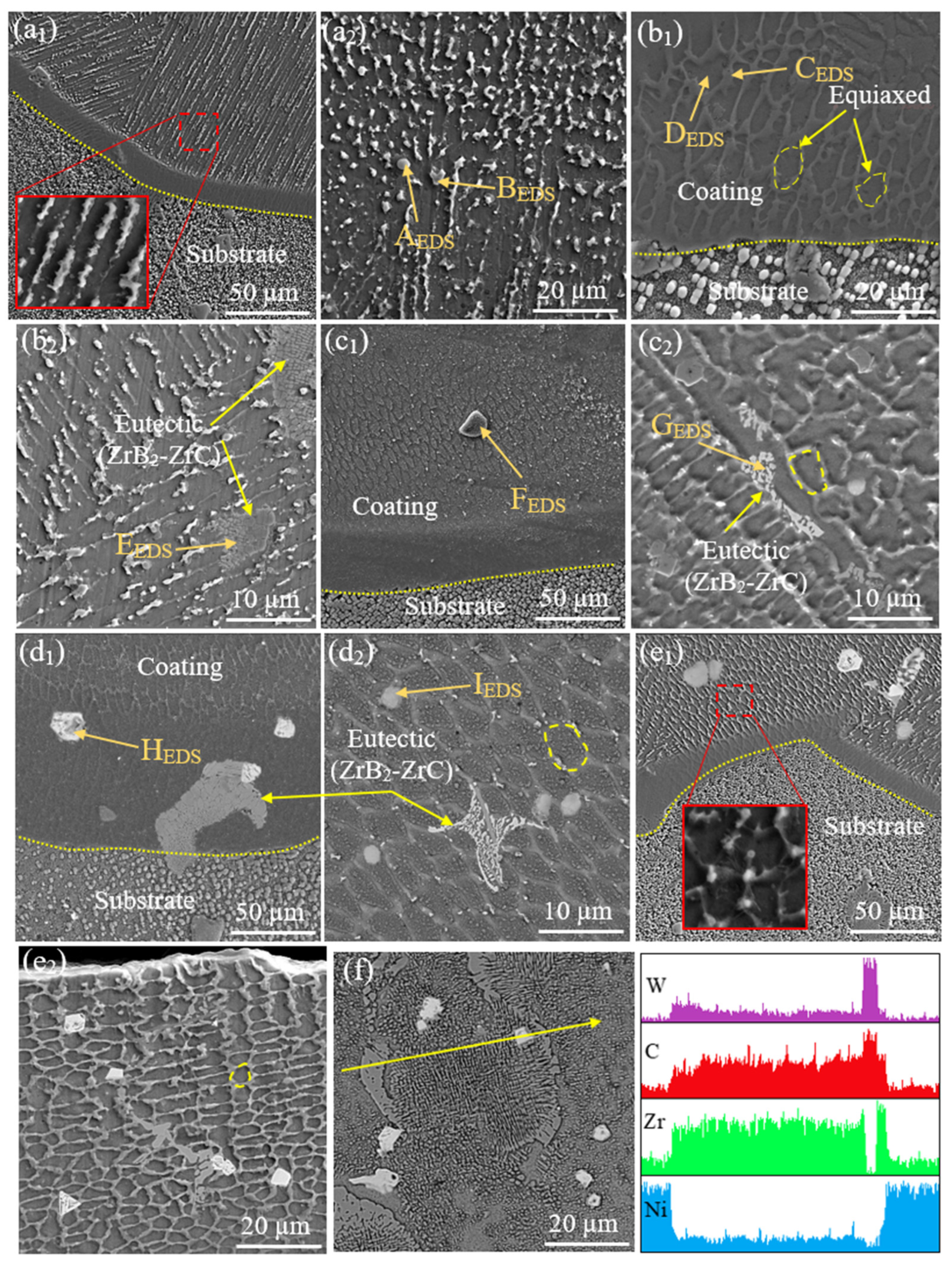
3.1. Microstructural Investigations

SEM images of the coating sections of different specimens are shown in Figure 3a–e. Detailed examination of the cross-section of the coating by Image j software (2018 version), which is also shown in Figure 3f, shows that the width and depth of the coating increase with the application of the ultrasonic field. This is despite the increase in the area of the coating pool without changing the laser cladding parameters. The investigation shows that with the increase in laser power, the size of the coating pool increases significantly due to the rise in heat input [27,28]. The ultrasonic field creates three effects of cavitation, streaming, and mechanical vibration in the molten pool [29], which in turn increases the heat input. Therefore, the increase in the cross-sectional area of the coating is attributed to these three effects. As a result, the increase in the area has increased from 2.92 mm2 for the MT0 specimen to 4.64 mm2 for the MT400, and this expanded area is an excellent success for ultrasonically assisted coating. This type of increase in the size of the coating basin not only does not cause harmful metallurgical changes in the coating and the heat-affected zone (HAZ) but also causes microstructure modification. One of the limitations of increasing the laser power is the creation of liquation cracks in the HAZ [30]. Zhang et al. [31] reported that with the increase in laser power in the coating of IN738 superalloy, the HAZ zone expands, and grain boundary melts are created around the γ′ phase, which becomes cracks by applying shrinkage stresses. In Figure 3, it is shown that the highest pores and porosity of 1.87% occurred in the MT0 coating (without ultrasonic). This occurred when applying the ultrasonic field; the set of pores and porosity was reduced so that in the power of 300 W (MT300 specimen), this amount reached 0%. By increasing the power to 400 W, the porosity increased again and reached the value of 0.15%. The high local pressure of the bubbles formed in the MT400 specimen created a high local heat around the bubble when it burst. This led to the formation of bubbles again, which resulted in an increase in pores again.
Figure 4 shows the XRD results for all five types of coatings. The change of the peaks in the observed patterns indicates the effect of the ultrasonic field on the formation of the coating. As can be seen, there are ZrC, WC, and α-Zr phases in the MT0 specimen pattern. By applying the ultrasonic field, the synthesized ZrB2 phase was also detected. In specimen MT400, a type of boride rich in Cr (CrB2) was detected. It seems that the decomposition of ZrB2 promotes the in situ synthesis of the reinforcement and causes the formation of this phase [32]. However, there is a possibility of forming carbide phases due to the decomposition of amplifiers with increasing ultrasonic power. However, due to the small amount, they cannot be detected by XRD. The change in the location of the peaks indicated the effect of the ultrasonic field on the distribution and amount of coating enhancers.
Figure 5 shows the microstructure of the coated specimen. As can be seen, the microstructure of the coatings consists of dendrites with different morphologies (columnar and equiaxed), which include two inter-dendritic regions and the core dendritic region. In the MT0 specimen (without ultrasonic), it can be seen that the top area of the coating contains equiaxed dendrites, and the bottom side of the coating contains columnar dendrites (no secondary arm). At the bottom of the coating, the cold wall of the substrate, with the increase in thermal conductivity, causes the rapid exit of heat from the molten pool (the temperature gradient is high). As a result, elongated dendritic arms are formed in the form of a column. On top of the coating, the fluid wall of the shielding gas makes the effect of displacement heat loss more prominent. As a result, small dendrites are solidified without an apparent direction of thermal conduction and convection heat loss. By applying the ultrasonic field, it can be seen that the microstructure of the coating on its top and bottom is rich in equiaxed dendrites. Therefore, with the increase in ultrasonic power, the size of dendrites decreases, especially at the bottom of the coating. It is reported in the literature that with the decrease in the size of the dendritic arms, the grain size and the grain aspect decrease [33]. The grain size for MT0~MT400 specimens is 27.4, 21.5, 16.7, 10.4, and 9.6 µm, respectively, and the grain aspect is 7.6, 6.2, 5.5, 2.4, and 2.1 for MT0~MT400 specimens, respectively. Since the horn and ultrasonic transducer are located in the lower part of the specimen (see Figure 2a), the lower part of the coating has finer grains than the upper part. Meanwhile, in various research, by placing the horn on top of the coating, the lower part of the coating was less likely to crumble [34]. In our previous work [26], where the horn and ultrasonic transducer were placed on the top of the specimen, this issue showed that the grains on the top of the coating were more refined than those on the bottom. However, compared to the previous research, the granulations in this work were more inclined towards equiaxed morphology because the ZrB2 particles do not melt in the melting pool and, therefore, create stronger inhomogeneous nucleation zones. In our previous work, the NbMoTaTiNi metal coating was melted after creating inhomogeneous nucleation zones.
In addition to the size of the dendrites, it can be seen in Figure 5a–e that reinforcements around the dendrites are enriched. The results of EDS analysis of marked points are listed in Table 3. It can be seen that Zr (in α-Zr form) is the main component of all the marked points. The issues around the main component of dendrites, which is rich in Zr, are rich in ZrC, which is the result of the decomposition of WC and a result of the in situ reaction between C and Zr at high temperatures during laser cladding. As seen in Figure 5c, ZrC forms a grain boundary eutectic through combination with ZrB2. By increasing the ultrasonic power from 100 W to 200 W, the dendrite size of the ZrC phase decreased, especially at the bottom of the coating, which is attributed to the effect of ultrasonic vibration. This increased ZrC in terms of number. With the increase in ZrC, the amount of Zr decreased. The reason for this is the consumption of Zr atoms by ZrC, which prevents the growth of α-Zr. By increasing the ultrasonic power to 200 W and 300 W, (1) the decomposition of elements caused the formation of Cr7C3 carbide, (2) the size of the dendrites became smaller, and the secondary dendritic arms increased, and (3) the increase in the temperature of the melt (due to the cavitation effect) increased the affinity the combination of B and Zr in the molten pool resulted in the formation of more ZrB2.
EDS linear analysis in Figure 5f shows that the characteristics of Zr distribution are similar to C and unlike Ni. This indicates that Ni is intentionally known as the γ-Ni field of coatings. As seen in the distribution of element W, there is no corresponding band between W and C. This indicates that both C and W elements are formed from WC decomposition. Also, the further decomposition of WC at 300 W and 400 W powers provides sufficient Zr atoms for the in situ synthesis of ZrC and the formation of Cr7C3 carbide.

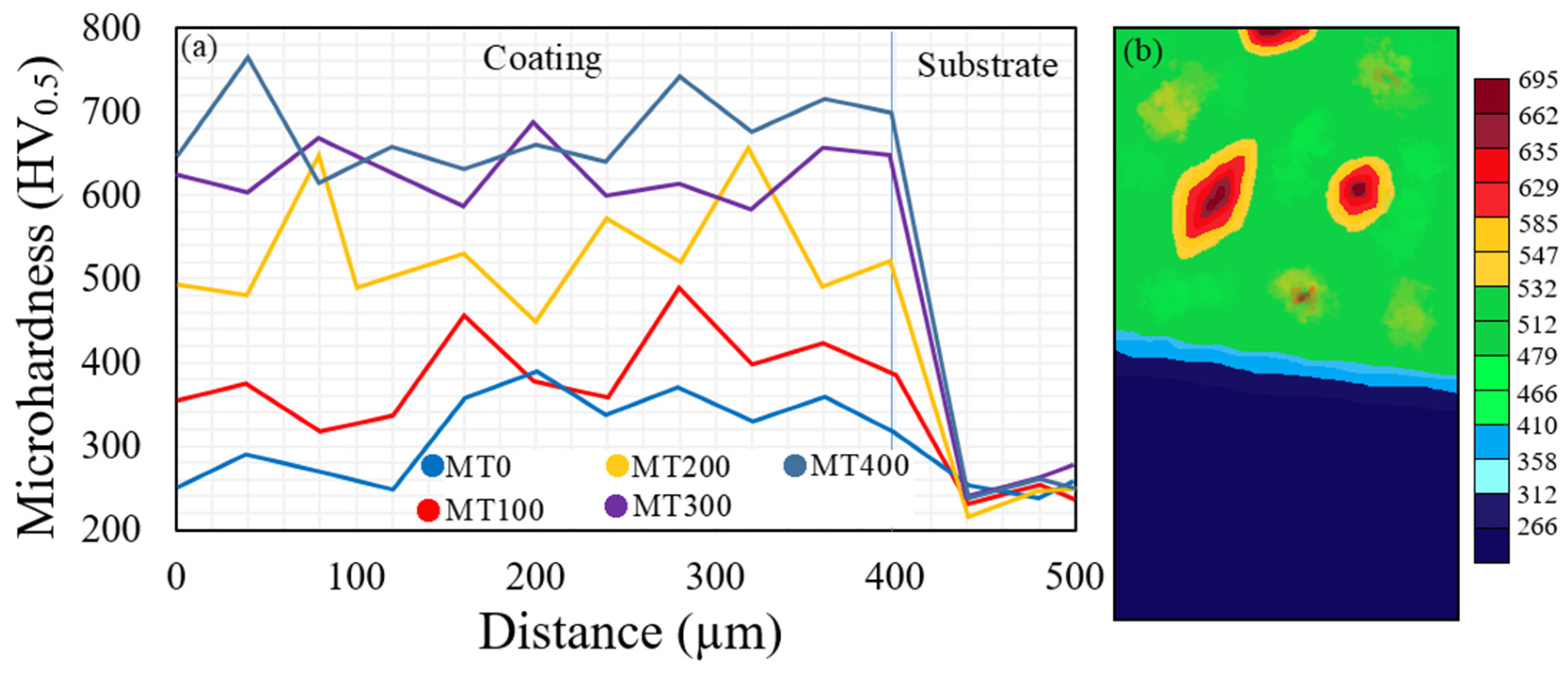
3.2. The Effect of Ultrasonic Power on Microhardness

Figure 6a,b shows the microhardness distribution and nephogram of the coating. The increase in the microhardness value from the GTD-111 substrate toward the coating indicates the correct performance of the coating composite, even in non-ultrasonic conditions. With the increase in ultrasonic power, the hardness of the coating experienced a significant increase. As a result, the average hardness for MT0~MT400 specimens is 312, 402, 526, 617, and 669 HV, respectively. This is due to two reasons: (1) increasing eutectic ZrB2-ZrC as the main factor increasing hardness, (2) crushing of dendrites and the tendency to form equiaxed grains with increasing ultrasonic power. The nephogram map in Figure 6b shows that the highest hardness value is around the reinforcing particles.

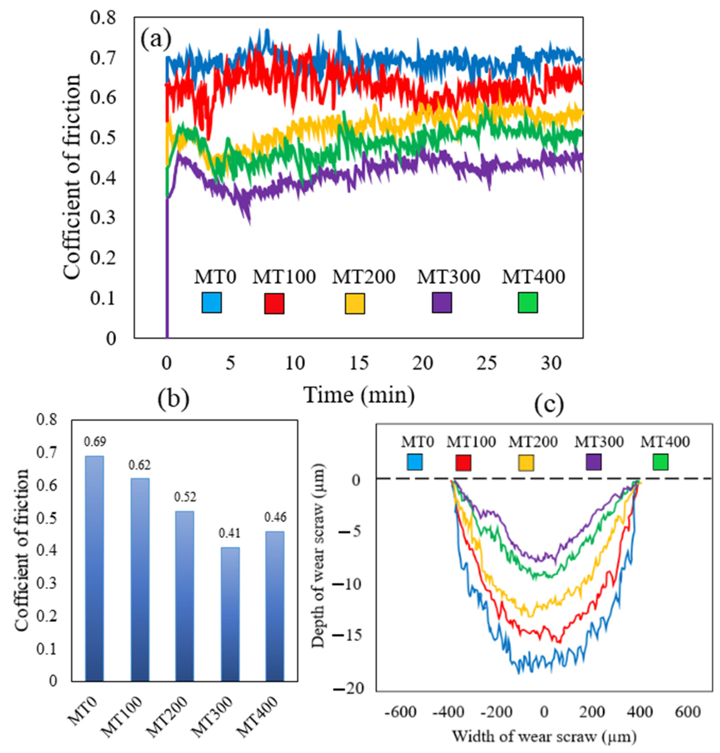
3.3. The Effect of Ultrasonic Power on Wear

The results of the coefficient of friction (COF) in Figure 7a show that the composite coating has a significant increase in the reduction of the COF compared to the substrate. Therefore, the average value of COF, according to Figure 7b for MT0~MT400 specimens, is 0.69, 0.62, 0.52, 0.41, and 0.46, respectively. ZrB2/ZrC- Ni60A/WC composite coating and grain refinement characteristics of the laser cladding process is the most important factor in increasing the wear resistance of MT0~MT400 specimens compared to the substrate. The scar wear results, as shown in Figure 7c, confirm the COF results. Therefore, the lowest wear scar wear with 6.8 µm belongs to the MT300 specimen, and the highest scar wear with 18.1 µm belongs to the MT0. Various reports have shown that the presence of holes and porosity in the wear path reduces the wear resistance through the increase in debris [35]. The MT0 specimen with about 1.87% voids experiences much greater wear depth than the MT300 specimen with 0% voids. Most of the voids formed in the MT0 specimen are gas holes caused by the evaporation of molten metal and the formation of plasma, which do not have a chance to escape due to the rapid solidification of the pool and become voids by being stuck in the inter-dendritic spaces. Meanwhile, these holes are removed by ultrasonic vibration according to the schematic presented in Figure 8. Mechanical vibrations remove the surrounding bubbles by creating high-speed shock waves during collapse [36]. By increasing the ultrasonic power up to 300 W, the number of cavities reaches 0%. At the power of 400 W, a slight increase in the hole is observed, which indicates the re-formation of the cavity due to the bursting of the holes. In fact, at a power of 400 W, cavitation causes excessive pressure on the holes, which will burst with a new wave of disturbance in the melting pool. This disturbance will be accompanied by the formation of new holes, which will turn into porosity soon after solidification. This has caused the MT400 specimen to show a lower wear resistance despite the finer grains than the MT300 specimen (Figure 7a–c).
The SEM images of the worn surface after the wear test in Figure 9 show that the addition of ZrB2/ZrC-Ni60A/WC composite coating removes plastic deformation areas, reduces spalling (reduction of depth) and areas of partial connection bonding (reduction of size). All reports show that the presence of WC, ZrB2, and ZrC increases wear resistance [37]. The above particles disperse the load at their point of contact with the wear pin and reduce the friction on the soft matrix. Therefore, reinforcing particles can reduce the plowing created during sliding wear, and somehow protect the coating (Ni) field and increase the wear resistance. Reducing adhesion and shear is one of the other benefits of reinforcements during wear. The effect of ultrasonic vibration increases the resistance of the coating against the invasion of the grinding ball by creating a uniform distribution of reinforcements. As seen in Figure 9, due to the high number of voids in the MT0 specimen, there is the most spalling and debris as well as plowing compared to the MT0~MT400 specimens. The most wear-resistant surface is the MT300 specimen, with an almost smooth surface. In short, it can be said that the uniform distribution of reinforcements, the formation of equiaxed grains, and the elimination of cavities are among the effects of ultrasonic mechanical vibration, which increases wear resistance.

4. Conclusions

In this research, ZrB2/ZrC-Ni60A/WC composite coating was coated on GTD-111 superalloy by ultrasonic vibration-assisted laser cladding, and the following results were obtained:
  • The appearance of all the resulting coatings was suitable. The highest cavity was obtained in the specimen without ultrasonic power (1.87%), and with the increase in ultrasonic power, the cavity value reached 0%;
  • The coating microstructure consisted of α-Zr, ZrB2, ZrC, and ZrC-ZrB2 eutectic. By increasing the ultrasonic power from 100 W to 400 W, the increase in heat input caused by the bursting of bubbles caused the decomposition of ZrB2 and WC;
  • The ultrasonic mechanical vibration caused the dendrites to be crushed, and the resulting acoustic effect caused the reinforcements to be uniformly distributed in the coating. This caused a significant increase in the microhardness of the coating from 312 HV to 669 HV, respectively, for specimens without ultrasonic and ultrasonic with 400 W power. ZrC–ZrB2 eutectic and ZrC reinforcements were the most important factors for increasing hardness;
  • The highest wear resistance was related to specimen MT300 with COF 0.41 and scar wear of 6.8 μm, and the lowest was related to specimen MT0 with COF 0.69 and scar wear of 18.1 μm. The uniform distribution of reinforcements, especially ZrC and ZrC–ZrB2, as well as the grain size reduction, grain aspect, and the tendency to form equiaxed grains, were the most important factors in increasing the wear resistance of the MT300 specimen;
  • The results of this research showed that the application of ZrB2/ZrC-Ni60A/WC coating by laser cladding method with scanning speed of 8 mm/s, average power of 200 W, powder feeding rate of 300 mg/s along with application of ultrasonic field in a contact form and from the bottom of the sample with ultrasonic frequency 23 kHz, and average power of 33 W produces the best tribological behavior due to the refined microstructure.

Author Contributions

Conceptualization, M.T.; Methodology, Z.W., M.T. and F.S.; Software, A.N., N.D. and G.K.; Investigation, Z.W., M.T., N.D. and G.K.; Data curation, A.N. and F.S.; Writing— original draft, M.T.; Writing—review and editing, M.T., N.D. and G.K.; Visualization, F.S. and N.D.; Supervision, M.T. and G.K.; Project administration, M.T. All authors have read and agreed to the published version of the manuscript.

Funding

This research received no external funding.

Institutional Review Board Statement

Not applicable.

Informed Consent Statement

Not applicable.

Data Availability Statement

Data are contained within the article.

Conflicts of Interest

The authors declare no conflict of interest.

References

  1. Yang, Y.; Nikolaidis, T.; Jafari, S.; Pilidis, P. Gas turbine engine transient performance and heat transfer effect modelling: A comprehensive review, research challenges, and exploring the future. Appl. Therm. Eng. 2023, 236, 121523. [Google Scholar] [CrossRef]
  2. Taheri, M.; Jam, J.E.; Beni, M.H.; Khorram, A.; Kashani-Bozorg, S.F.; Torkamany, M.J. The effect of service temperature on the impact strength and fracture toughness of GTD-111 superalloy. Eng. Fail. Anal. 2021, 127, 105507. [Google Scholar] [CrossRef]
  3. Li, D.-W.; Liu, J.-X.; Sun, Y.-T.; Huang, W.-Q.; Li, N.; Yang, L.-H. Microstructure and mechanical degradation of K403 Ni-based superalloy from ultra-long-term serviced turbine blade. J. Alloys Compd. 2023, 957, 170378. [Google Scholar] [CrossRef]
  4. Villada, J.A.; Bayro-Lazcano, R.G.; Martinez-Franco, E.; Espinosa-Arbelaez, D.G.; Gonzalez-Hernandez, J.; Alvarado-Orozco, J.M. Relationship between γ′ phase degradation and in-Service GTD-111 first-stage blade local temperature. J. Mater. Eng. Perform. 2019, 28, 1950–1957. [Google Scholar] [CrossRef]
  5. Zarei, F.; Nuranian, H.; Shirvani, K. Development of FeAl Coatings by a Combined Aluminizing Process to Improve the Dry Sliding Wear Resistance of HH309 Alloy. J. Mat. Eng. Perform. 2022, 31, 7337–7352. [Google Scholar] [CrossRef]
  6. Maniam, K.K.; Paul, S. Progress in novel electrodeposited bond coats for thermal barrier coating systems. Materials 2021, 14, 4214. [Google Scholar] [CrossRef]
  7. Farias, F.W.C.; da Cruz Payão Filho, J.; da Silva Júnior, D.A.; de Moura, R.N.; Rios, M.C.G. Microstructural characterization of Ni-based superalloy 625 clad welded on a 9% Ni steel pipe by plasma powder transferred arc. Surf. Coat. Technol. 2022, 374, 1024–1037. [Google Scholar] [CrossRef]
  8. Liu, H.-L.; Liu, J.-X.; Bao, W.-C.; Xu, F.-F.; Zhang, G.-J. Interface characteristics in ZrB2-based ceramics containing SiC and/or ZrC particles via hot-pressing sintering. Mater. Charact. 2021, 176, 111144. [Google Scholar] [CrossRef]
  9. Borhani, M.R.; Rajabi, M.; Razavi, R.S.; Jamaati, R. Investigating the relationship between mechanical properties and residual stress in the laser cladding process of Inconel 625 superalloy. Heliyon 2023, 9, e19791. [Google Scholar] [CrossRef]
  10. Gudivada, G.; Pandey, A.K. Recent developments in nickel-based superalloys for gas turbine applications: Review. J. Alloys Compd. 2023, 963, 171128. [Google Scholar] [CrossRef]
  11. Szczepankowski, A.; Przysowa, R.; Perczyński, J.; Kułaszka, A. Health and Durability of Protective and Thermal Barrier Coatings Monitored in Service by Visual Inspection. Coatings 2022, 12, 624. [Google Scholar] [CrossRef]
  12. Wang, J.; Zhang, Y.; Cui, Y.; Hu, H.; Zhang, L.; Chen, L. High temperature wear behavior of NiCoCrAlY-Cr2O3-AgMo coating on GH4169 superalloy. Mater. Today Commun. 2023, 35, 105762. [Google Scholar] [CrossRef]
  13. Zhao, J.; Taheri, M.; Shirvani, K.; Alizadeh, H.; Palay, M.A. Improving the Microstructure and Wear Behavior of Gas Turbine Compressor Parts Through the Application of FeCoNiCuAl–WC High Entropy Composite Coating by Laser Cladding. Metals Mater. Int. 2023, 1–11. [Google Scholar] [CrossRef]
  14. Lu, P.-Z.; Jia, L.; Zhang, C.; Heng, X.; Xi, X.-C.; Duan, M.-F.; Lu, Z.-L.; Zhou, Y.-X. Optimization on laser cladding parameters for preparing Ni60 coating along with its friction and wear properties. Mater. Today Commun. 2023, 37, 107162. [Google Scholar] [CrossRef]
  15. Ilanlou, M.; Razavi, R.S.; Nourollahi, A.; Hosseini, S.; Haghighat, S. Prediction of the geometric characteristics of the laser cladding of Inconel 718 on the Inconel 738 substrate via genetic algorithm and linear regression. Opt. Laser Technol. 2022, 156, 108507. [Google Scholar] [CrossRef]
  16. Wang, K.; Liu, W.; Hong, Y.; Sohan, H.M.S.; Tong, Y.; Hu, Y.; Zhang, M.; Zhang, J.; Xiang, D.; Fu, H.; et al. An Overview of Technological Parameter Optimization in the Case of Laser Cladding. Coatings 2023, 13, 496. [Google Scholar] [CrossRef]
  17. Deng, P.; Yao, C.; Feng, K.; Huang, X.; Li, Z.; Li, Y.; Zhao, H. Enhanced wear resistance of laser cladded graphene nanoplatelets reinforced Inconel 625 superalloy composite coating. Surf. Coat. Technol. 2018, 335, 334–344. [Google Scholar] [CrossRef]
  18. Li, X.; Zhang, S.; Liu, W.; Pang, X.; Tong, Y.; Zhang, M.; Zhang, J.; Wang, K. Effect of WC Content on the Wear and Corrosion Properties of Oscillating Laser-Cladding-Produced Nickel-Based Coating. Coatings 2023, 13, 1614. [Google Scholar] [CrossRef]
  19. An, G.-S.; Li, W.-S.; Wang, Z.-P.; Feng, L.; Cheng, B.; Zhou, L.; Li, Z.-Y.; Zhang, Y. High-temperature oxidation and TGO growth behaviors of laser-modified YAG/YSZ double-ceramic-layer TBC. Trans. Nonferrous Met. Soc. China 2023, 33, 1178–1192. [Google Scholar] [CrossRef]
  20. Chen, Z.; Zhang, C.; Zhang, J.; Zhang, Y.; Wu, W.; Li, G.; Lu, X. Temperature field simulation of Ni60A coating with different copper content on blast furnace tuyere. Mater. Today Commun. 2022, 32, 104093. [Google Scholar] [CrossRef]
  21. Huang, K.; Xia, Y.; Wang, A. High Temperature Oxidation and Oxyacetylene Ablation Properties of ZrB2-ZrC-SiC Ultra-High Temperature Composite Ceramic Coatings Deposited on C/C Composites by Laser Cladding. Coatings 2023, 13, 173. [Google Scholar] [CrossRef]
  22. Shirani, M.; Rahimipour, M.; Zakeri, M.; Safi, S.; Ebadzadeh, T. ZrB2-SiC-WC coating with SiC diffusion bond coat on graphite by spark plasma sintering process. Ceram. Int. 2017, 43, 14517–14520. [Google Scholar] [CrossRef]
  23. Khalaj, G.; Soleymani, F.; Sharifi, F.; Najafi, A. Evaluation of APC impact on controlling precursors properties in the sol for synthesizing meso porous ZrC nanopowder through sol-gel process. J. Mater. Res. Technol. 2023, 26, 6182–6192. [Google Scholar] [CrossRef]
  24. Cao, Y.; Farouk, N.; Taheri, M.; Yumashev, A.V.; Bozorg, S.F.K.; Ojo, O.O. Evolution of solidification and microstructure in laser-clad IN625 superalloy powder on GTD-111 superalloy. Surf. Coat. Technol. 2021, 412, 127010. [Google Scholar] [CrossRef]
  25. Huang, X.; Chen, Y.; Jiang, J.; Lian, G.; Chen, C. The Influences of Ultrasonic Vibrations on Laser Cladding Ni60/WC-TiO2+ La2O3 Composite Coating. Materials 2023, 16, 6356. [Google Scholar] [CrossRef] [PubMed]
  26. Zhao, S.; Taheri, M.; Shirvani, K.; Naserlouei, M.; Beirami, K.; Paidar, M.; Sai, W. Microstructure of NbMoTaTiNi Refractory High-Entropy Alloy Coating Fabricated by Ultrasonic Field-Assisted Laser Cladding Process. Coatings 2023, 13, 995. [Google Scholar] [CrossRef]
  27. Lindner, T.; Günen, A.; Töberling, G.; Vogt, S.; Karakas, M.S.; Löbel, M.; Lampke, T. Boriding of Laser-Clad Inconel 718 Coatings for Enhanced Wear Resistance. Appl. Sci. 2021, 11, 11935. [Google Scholar] [CrossRef]
  28. Jelvani, S.; Razavi, R.S.; Barekat, M.; Dehnavi, M.R.; Erfanmanesh, M. Evaluation of solidification and microstructure in laser cladding Inconel 718 superalloy. Opt. Laser Technol. 2019, 120, 105761. [Google Scholar] [CrossRef]
  29. Wang, Y.; Li, C.; Jiang, F.; Zhang, J.; An, X. Microstructure and mechanical properties of ultrasonic assisted laser cladding Al2O3–ZrO2 ceramic coating. Mater. Res. Express 2019, 6, 106563. [Google Scholar] [CrossRef]
  30. Kołodziejczak, P.; Golański, D.; Chmielewski, T.; Chmielewski, M. Microstructure of Rhenium Doped Ni-Cr Deposits Produced by Laser Cladding. Materials 2021, 14, 2745. [Google Scholar] [CrossRef]
  31. Zhang, B.; Shirvani, K.; Taheri, M.; Beirami, K.; Wang, Y. Effect of TiC and Magnetic Field on Microstructure and Mechanical Properties of IN738 Superalloy Processed by Selective Laser Melting. J. Mater. Eng. Perform. 2023; in press. [Google Scholar] [CrossRef]
  32. Lashkari, A.H.; Moghaddam, A.O.; Naseri, M.; Shokuhfar, A. Synthesis and characterization of high entropy carbide-MAX two-phase composites. J. Mater. Res. Technol. 2023, 24, 5024–5031. [Google Scholar] [CrossRef]
  33. Chang, L.; Yanpeng, Y.; Zhaotai, L.; Xin, H.; Tenghui, J. Differential analysis of the influence mechanism of ultrasonic vibrations on laser cladding. CIRP J. Manuf. Sci. Technol. 2022, 38, 16–37. [Google Scholar] [CrossRef]
  34. Xiao, M.; Jiang, F.; Guo, C.; Song, H.; Dong, T. Investigation on microstructure and mechanical properties of Fe-based amorphous coatings prepared via laser cladding assisted with ultrasonic vibration. Opt. Laser Technol. 2023, 162, 109294. [Google Scholar] [CrossRef]
  35. Wu, H.; Wang, L.; Zhang, S.; Wu, C.; Zhang, C.; Sun, X.; Chen, J. Tribological properties and sulfuric acid corrosion resistance of laser clad CoCrFeNi high entropy alloy coatings with different types of TiC reinforcement. Tribol. Int. 2023, 188, 108870. [Google Scholar] [CrossRef]
  36. Wang, J.; Zhou, J.; Zhang, T.; Meng, X.; Li, P.; Huang, S.; Zhu, H. Ultrasonic-Induced Grain Refinement in Laser Cladding Nickel-Based Superalloy Reinforced by WC Particles. Coatings 2023, 13, 151. [Google Scholar] [CrossRef]
  37. Zhou, X.; Gao, Y.; Wang, Y.; Xiao, P.; Huang, X. Effects of ZrC particles, load and sliding speed on the wear behavior of the ZrC/2024Al composites. Wear 2022, 506, 204465. [Google Scholar] [CrossRef]
Figure 1. Morphology of powders used in the beta composite, (a) Ni60A-WC, (b) ZrB2, (c) ZrC.
Coatings 13 01928 g001
Figure 2. (a) Schematic of the laser cladding process used, (b) Wear test schematic.
Coatings 13 01928 g002
Figure 3. Coating cross-section of specimens (a) MT0, (b) MT100, (c) MT200, (d) MT300, (e) MT400, (f) Change of coating cross-section dimensions with changing ultrasonic power.
Coatings 13 01928 g003
Figure 4. XRD pattern of the coating at different ultrasonic powers.
Coatings 13 01928 g004
Figure 5. Microstructure of coating samples: (a1,a2) MT0, (b1,b2) MT100, (c1,c2) MT200, (d1,d2) MT300, (e1,e2) MT400, (The bottom and top of the coating are shown with the captions 1 and 2, respectively), (f) Linear EDS analysis of MT300 sample coating.
Coatings 13 01928 g005
Figure 6. (a) Changes in coating hardness with increasing ultrasonic power, (b) distribution of indentation and the nephogram of microhardness of clad zone.
Coatings 13 01928 g006
Figure 7. The wear test results of MT1~MT400 samples, (a,b) COF, (c) Scar wear.
Coatings 13 01928 g007
Figure 8. Schematic of the process of the effect of cavitation effect on the solidification of the coating pool.
Coatings 13 01928 g008
Figure 9. SEM morphologies of wear marks, (a) MT0, (b) MT100, (c) MT300.
Coatings 13 01928 g009
Table 1. Chemical composition of GTD-111 superalloy (wt.%) [26].
CrCoTiAlTaWMoNbBZrCNi
149.64.93.12.83.81.50.070.0140.030.1Bal
Table 2. Laser cladding and ultrasonic parameters.
SpecimenLaser Average Power (W)Laser Scan Speed (mm/s)Powder Feeding Rate (mg/s)Ultrasonic Frequency (kHz)Ultrasonic Power (W)
MT0200830023-
MT100200830023100
MT200200830023200
MT300200830023300
MT400200830023400
Table 3. The results of the EDS analysis of the marked points in Figure 5.
PointZrBWCCrNiPossible Phase
A61.05-0.5832.950.222.45ZrC
B98.41-0.48-0.290.82α-Zr
C96.52-0.05-1.072.36α-Zr
D5.851.58-0.577.9684.05α-Ni
E37.4135.82-21.653.581.54ZrB2-ZrC
F56.36-0.5437.890.434.78ZrC
G36.1738.75-19.254.221.61ZrB2-ZrC
H--61.5536.420.441.59WC
I22.7845.253.2224.682.111.96ZrB2
Disclaimer/Publisher’s Note: The statements, opinions and data contained in all publications are solely those of the individual author(s) and contributor(s) and not of MDPI and/or the editor(s). MDPI and/or the editor(s) disclaim responsibility for any injury to people or property resulting from any ideas, methods, instructions or products referred to in the content.

