
Microstructure and Tribological Performance of HVAF-Sprayed Ti-6Al-4V Coatings
by
 ,
,
Tunji A. Owoseni
* ,
,
Irene Ciudad de Lara
,
Sribalaji Mathiyalagan
,
Stefan Björklund
and
Shrikant Joshi

Department of Engineering Science, University West, SE-46186 Trollhättan, Sweden
*
Author to whom correspondence should be addressed.
Coatings 2023, 13(11), 1952; https://doi.org/10.3390/coatings13111952
Submission received: 16 October 2023
/
Revised: 2 November 2023
/
Accepted: 10 November 2023
/
Published: 15 November 2023
(This article belongs to the Special Issue Mechanical Properties and Tribological Behavior of Alloy/Coatings)
Abstract
:Ti-6Al-4V is a widely used titanium alloy in aviation and bio/chemical applications for its attractive mechanical and corrosion resistance properties. The use of Ti-6Al-4V as a coating for repair purposes through thermal spray techniques provides a unique productivity opportunity. A repair coating must be dense to provide the required in-service functionalities, such as resistance to wear. The High Velocity Air Fuel (HVAF) thermal spray technique deposits dense coatings with reduced concern for oxide inclusions. This work presents an investigation of the microstructure, dry sliding, and solid particle erosive wear performance of four different coatings engineered through the configuration of the nozzle of an HVAF spray gun, based on the length of the nozzle and the size of the nozzle exit. A long nozzle length and wide nozzle exit mean increased inflight dwell time and reduced average inflight temperature for the sprayed particles, respectively—a reversed configuration means the opposite. The tested coatings showed a porosity of less than 2%. The sliding and erosion wear performance of the densest of the coatings compares to that of the bulk material tested under the same conditions. Electron microscopy was used to investigate the driving mechanisms for the performance of the respective coatings. The implications of the results are discussed for the potential adoption of HVAF-sprayed coatings in metal component repair.
1. Introduction
Ti64 alloy makes up 50% of the alloys of titanium used in biomedical, chemical, automotive, and mostly in the aerospace industry. The aerospace sector consumes 80% of Ti64 alloy, while other applications account for the remaining 20% [1]. Ti64 alloy is designed for a good balance of engineering properties like the following:
- Ductility and workability;
- Fracture toughness;
- Heat and creep resistance;
- Weldability, thermal processability, and strength [2].
Titanium materials are the usual feedstock for powder-based additive manufacturing and for new repair technologies, such as thermal spray techniques [3]. Titanium alloys are very useful, but they are costly. It is cost-effective and environmentally friendly to be able to repair and remanufacture damaged structural engineering components made of titanium alloys to extend their service lifespan—instead of complete replacement. The repair of worn/damaged engineering components forms part of the ongoing sustainability efforts in the aerospace industry to combat climate change.
Repairs are a major issue in the aerospace industry, and there are ongoing efforts to improve subsisting manufacturing methods, including repairs, to cut costs and reduce operation losses [4]. While many of the components of an aircraft engine are still being made from Ti64 alloys (see Figure 1), there is a need to find an economic and sustainable way to further explore the much-appreciated properties of the alloys. Repairs in aero engine parts are mostly performed by welding Tungsten Inert Gas (TIG); where welding is impractical, the parts are replaced [5]. Conventional welding processes engender an energetic impact on parts being repaired and can make the part heavier. Welding also creates heat-affected zones in the substrates to cause changes in the properties of the affected zone—the localized change in properties gives further concern [6,7]. Thermal spray is an attractive material deposition method to create coatings needed for the surfacing and resurfacing of parts [8]. Thermal spray offers many advantages, such as low heat transfer to the substrate, improved engineering performance, and extending the component’s lifespan at a relatively low cost. Thermal spray can deposit coatings of varying thicknesses, from a few microns to several millimetres. Thermal spray coatings have been sprayed from all classes of materials, including metals, ceramics, polymers, ceramics, and cermet, without concern for the form of the material being a powder, wire, rod, dispersed in a liquid (suspension), or formed in situ from a solution precursor [9,10,11,12,13].
From a repair point of view, thermal spray produces dense, homogenous coatings that add insignificant mass to the size of a component. Despite the insignificant size of a coating relative to a coated component, a dense homogenous coating offers similar protection, as will a bulk sample of the coating material feedstock [14]. The key to ensuring the controlled microstructure of a coating lies in the adopted spray technique [15], the spray parameters/conditions [16], and the characteristics of the feedstock materials [17]. The aerospace industry has explored this capability of thermal spray with the high-velocity oxy-fuel (HVOF) thermal spray technique for repair. The HVOF repair route shows significant merits over welding; it reduces part distortion after repair in addition to coating thin, porosity-free layers over the damaged parts. However, HVOF overlay coatings are rough, and a part coated with HVOF requires secondary machining steps to ensure an improved surface finish—this is besides the possibility of in-flight oxidation of the feedstock deposited via HVOF. This is a concern for oxidation-sensitive materials like titanium alloys, which have also limited their application. For this work, the feedstock is a Ti-6Al-4V powder deposited via HVAF, a thermal spray technique with the capacity to deposit dense coatings with reduced/no oxide formation while transferring limited heat to the coated substrate—HVAF coating also maintains good interfacial bonding with the coated substrate [2,17]. The earlier stated benefits guided the choice of HVAF above the known industrially employed techniques APS and HVOF [18,19]. This paper aims to investigate the implication of HVAF hardware spray configuration on the microstructure, mechanical properties, and wear resistance of HVAF-sprayed Ti-6Al-4V coatings deposited on Ti-6Al-4V substrates. Coatings were deposited using four different spray gun configurations; the respective coatings were then studied from a processing-property-performance perspective to elicit a pathway for developing coatings usable for repair purposes.
2. Experimental
2.1. Materials
Two commercially sourced powdered feedstocks were used in this work—one as thermal spray feedstock and the other as an erodent material for performance evaluation. An experimental powdered feedstock of Ti-6Al-4V from AP&C (Quebec, QC, Canada) was used for the HVAF deposition. The as-received powder particles were quoted to have a particle size distribution (D50) in the range of 17–34 μm with a standard deviation of 10.9 µm. Alumina powder from AP&C (Quebec, QC, Canada) was used as the erodent for the erosion wear test performed on the as-sprayed coatings. The alumina powder was oven-dried at 150 °C for 24 h to remove inherent moisture. The substrate used for the coating deposition was Ti-6Al-4V, otherwise referred to as bulk Ti64 in subsequent sections. The substrates were grit-blasted with standard alumina particles to create mechanical interlock points on the substrates’ top surface.
2.2. Alloy Coating Deposition
The alloy coatings deposited from the Ti64 feedstock were completed using a deLaval convergent–divergent nozzle in an HVAF spray process setup (M3, UniqueCoat Technologies LLC, Oilville, VA, USA) running on propane fuel. The spray process utilized four different nozzle configurations—each configuration for a spray run (see Table 1)—to make four different coating samples. The spray parameters used during the spray session are presented in Table 2.
2.3. Characterization and Performance Tests
2.3.1. Sample Preparation and Microstructure Analysis
The morphology and particle size of the as-supplied powder feedstock were examined in the secondary electron (SE) mode through the scanning electron microscopy technique using ZEISS Gemini field emission SEM equipped with an Oxford AZtec energy-dispersive (EDS) detector. A sparse distribution of the powder on the stub was gold-coated before the scanning electron imaging. The ZEISS SEM was also used to obtain micrographs of the coating top surface as well as the wear tracks/spots of the tested coating surfaces. The top surface micrographs, in SE mode, provide insight into the coating build-up, while the wear track micrographs provide insight into wear mechanisms. The micrographs of the coating cross-sections were obtained in backscattered electron (BSE) mode using a tabletop SEM (TM3000, HITACHI, Tokyo, Japan). The cross-section micrographs provide insight into the coating thickness and the possible defect (pores, cracks, and voids) distribution across the coating spread. The coating cross-section was prepared from hot-mounted, as-sprayed coupons sectioned using a precision cutter before the cut samples were polished according to standard metallographic procedures. The coating porosity was estimated from multiple cross-sectional micrographs using Image-J software (Image J 1.53e, Fiji, Dresden, Germany). The estimated porosity of the respective coating samples is reported with the associated standard error.
2.3.2. Microhardness
A microhardness test was carried out on samples of the coatings deposited from each spray run. The hardness test was conducted on a polished cross-section of the coating samples using a Vickers indenter (Duramin-40, Struers, Willich, Germany) at an indenter load of 200 gf sustained for 10 s. Each measurement consists of ten indents to report the average microhardness with the associated standard error.
2.3.3. Wear Performance Tests
The sliding wear test was conducted using the ball-on-disk configuration on the tribometer machine (TRB3, Anton Paar, Breda, The Netherlands) as per the ASTM G99 standard. The counter body was a stainless-steel ball of 6 mm diameter. The choice of stainless-steel counter body was to provide for in-service conditions. The load applied (P) onto the disk was 5 N to complete a total sliding distance of 100 m—see the schematic of the test process as shown in Figure 2. The specific wear rate (SWR) was obtained from the combined measurement of the wear track area and the track length using Profilm 3D white light interferometry (Filmetrics Europe GmbH, Unterhaching, Germany). The specific wear rate was thus the ratio of the volumetric material loss to the product of the total sliding distance and the normal contact load.
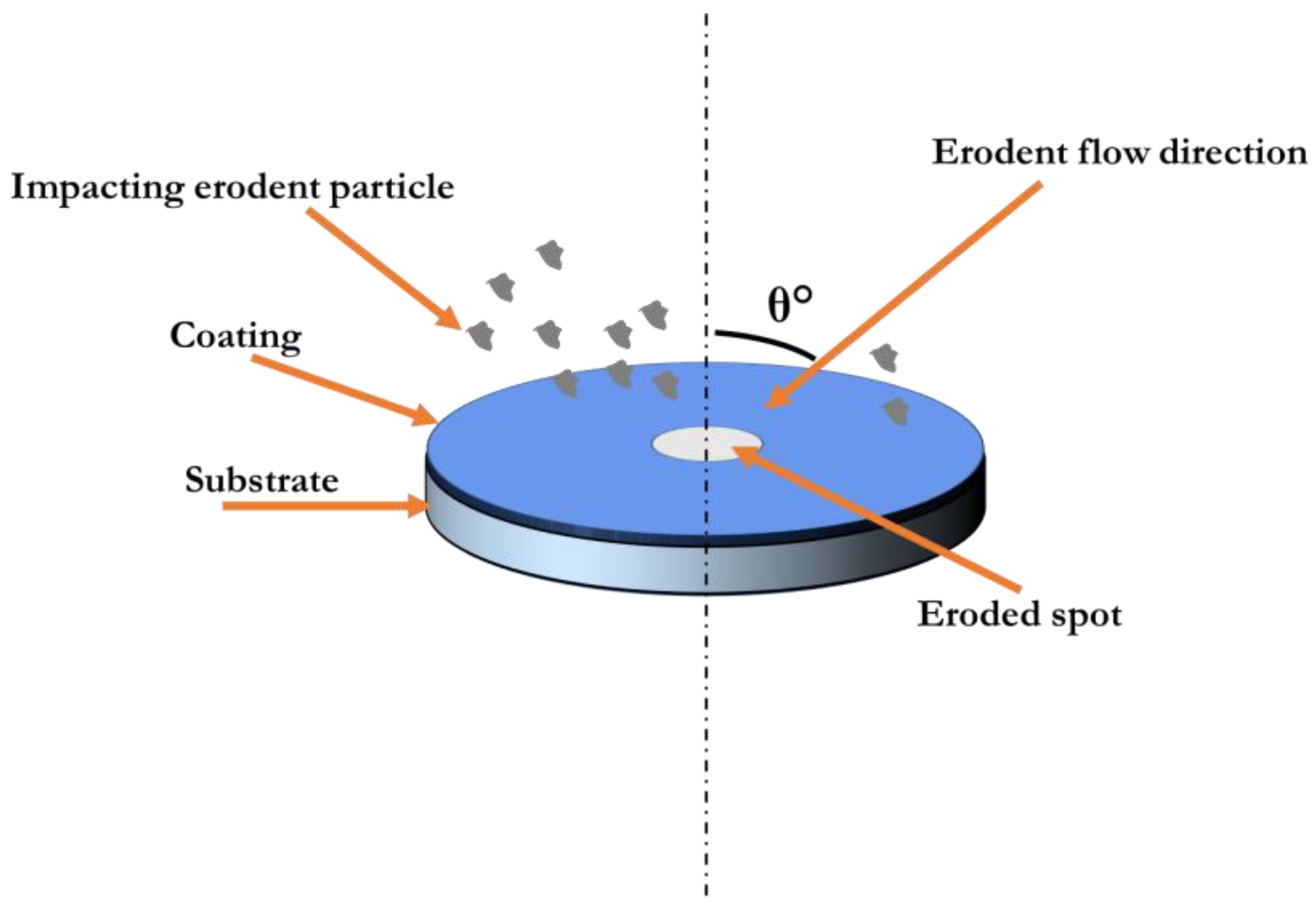
The erosion test was conducted on the Air Jet Erosion Tester TR-470 using alumina erodent powder. The erodent average flow rate was 2 g/min, and the impact velocity was set at 70 m/s for three different impingement angles (30°, 60°, and 90°)—see Figure 3. The choice of the impingement angle was to test the response of the deposited coatings under the envisaged in-service condition. Each erosion test was run for 2 min before the erosion rate for each impingement angle was recorded through a weight loss approach. The weight loss was measured using the machine MyCal from PCE instruments, model AB-100, with a sensitivity of 0.0001 g, while the surface roughness was measured using Surftest 301 from Mitutoyo (Kawasaki, Japan).
The erosion rate was calculated as the volume loss divided by the mass of erodent particles. Volume loss is the weight loss divided by the density of the coating, taken as 4.5 g/cm3. The mass of the erodent particles used per test session was estimated as the flow rate of the erodent multiplied by the test duration. In this case, 2 g/min multiplied by 2 min gives 4 g of erodent particles.
3. Results and Discussion
3.1. Microstructure: Materials and as-Sprayed Coatings
The secondary electron micrograph of the Ti64 powder shown in Figure 4 presents a loose powder with spherical morphology. The spherical morphology is indicative of the free-flow feedstock required for coating deposition. The particle size distribution plot is in Figure 4b, suggesting most of the particles are around 30 μm in size.
The erodent alumina material is presented in Figure 5. The secondary electron micrograph shows the particles are angular, with the bulk of the particles being in the size range of 40–70 μm, as shown in Figure 5b. The powder morphology suggests a reduced flowability, a reason for the prolonged oven drying of 24 h before the erosion wear test as given in Section 2.1.
Backscattered electron micrographs of the as-sprayed coatings are shown in Figure 6 and Figure 7. The images present the cross-section of the coatings, showing the coating substrate interface, inter-splat boundary, pores, and coating thickness. The microstructure of the four coatings shows a stack of unmolten individual particles with varied plastically deformed shapes. This observation suggests the as-received powder particles have lost their respective spherical morphology, as presented in Figure 4. Each of the coatings presents with a different porosity level via a visual inspection. A quantitative measure of the porosity for the individual coatings using image-J software suggests the coating from run-4 (see Table 3) has the least porosity—less than 0.5%. Run-1 shows a porosity level of 2%–3%, which is the highest of the four coatings, while run-2 and run-3 have 0.5%–1% and 1%–2% porosity levels, respectively. Coatings deposited via HVAF have a high density resulting from the hypersonic impact velocity [2]. This feature of the HVAF spray technique engenders a compact overlay of plastically deformed, softened feedstock. The identified porosity on the cross-section of the coatings is formed from the inter-boundary particle geometries, however deformed; as such, the pores have irregular geometries depending on the morphology of the adjoining particles.
The characteristic features of a coating microstructure are also affected by the spray system hardware configuration [22]. The configuration of the nozzle used for each of the coating samples affects the microstructure of the coatings. The long nozzle with a wide exit meant longer dwell time for the particles in-flight, creating softened and/or molten particles that are deposited as splats. A reduced dwell time owing to the short nozzle length would mean the coating build-up elements will have more softened particles than splats; the reverse is also valid. The exit size affects the deposition velocity, and an enlarged exit means the coating build-up will rely on the thermal heating of the impacting particles rather than the impact energy due to particle velocity. The coatings sample in run-1 is built mostly based on the thermal energy of the particles because they have a longer dwell time inflight arriving at the substrate surface with reduced velocity through a wide exit, in contrast to the run-2 sample, which combined a longer dwell time due to the long nozzle length with a small exit. The former shows the highest porosity compared to the latter, which has the least porosity. This observation suggests the dwell time makes for the deposition efficiency of sprayed particles; it requires high impact velocity to build dense coatings with reduced porosity. The small exit configuration for the sample from run-4 further justifies the influence of the deposition velocity of the particles. The four coatings are deposited in the parameter window that produces mostly softened particles, as proved in the work of Browning [2]. It is a trade-off between deposition efficiency and coating density vis à vis the nozzle length and exit size; deposition efficiency drops with high impact velocity due to the bounce-off effect given that the feedstock particles are only softened and not molten. This explains the higher thickness of the coating sample in run-1 compared to the 50% loss of material in run-2 for the same number of passes and longer dwell time engendered by the long nozzle length. The deposition efficiency as a measure of the coating thickness is preserved in addition to the coating density with a short-length nozzle and a small-nozzle exit. This will have a significant productivity impact because a short nozzle length would mean coating deposition in a shorter time.
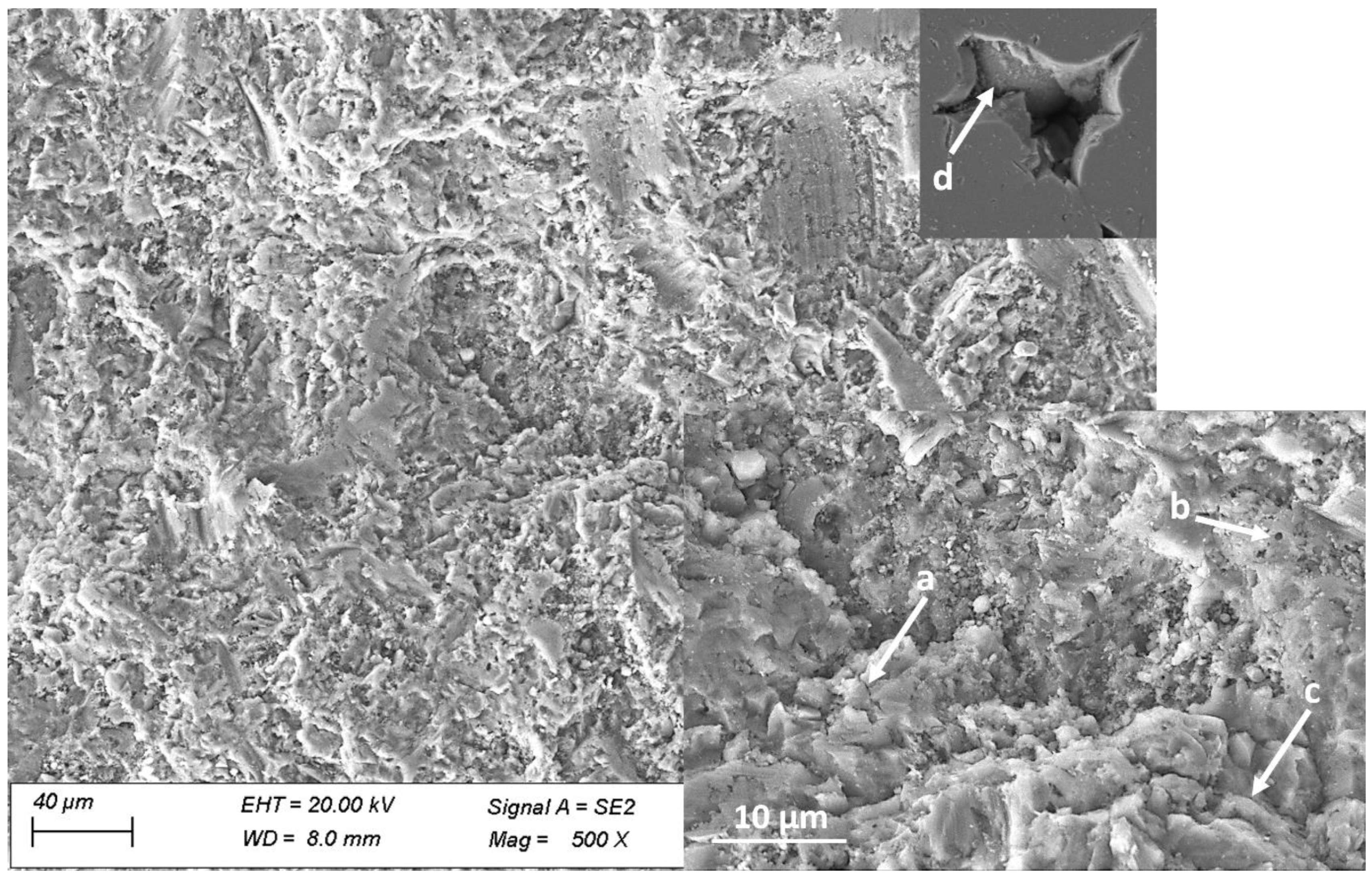
The top surface morphology of coatings reveals the makeup of a thermal spray coating. It shows the spread of deposited materials when molten [23,24], clusters of materials that may be partly molten, or materials retained from the sprayed feedstock [25]. The four coating samples (runs 1–4) show consistency in this regard; the top surface of each of the coatings presents mostly highly deformed materials. A representative micrograph of the coating’s top surface is shown in Figure 8. The coating buildup consists of layers of deformed materials well distributed to cover the entire substrate’s top surface. The key features of the deformed material overlays are shown in the inset, which reveals the inter-particle boundary, microcrack, and blind pores. A magnified void in the top right-hand corner of Figure 8 shows a buried, undeformed particle from the sprayed feedstock. The inter-particle boundaries of the deformed materials are close, suggesting good interlayer bonding. There are, however, some micro-cracks; those would have developed from cooling transformation stresses.
3.2. Microhardness and Wear Performance
3.2.1. Microhardness
Given the varied microstructural build-up of the individual coatings as shown by the respective cross-sectional views presented in Section 3.1, it is expected that each of the coatings will show different resistance to local plastic deformation measured using Vickers hardness. Figure 9 shows the measured hardness of the respective coatings with the associated standard error. However, the upper and lower limits for all the samples lie in the range of 320 and 400 HV. The processing condition seems not to cause any significant variation in the microhardness of the samples. The dominant microstructural defect in all the coatings is porosity, with varied percentages as presented in Table 3. Nonetheless, all the coatings show similar resistance to local plastic deformation. In each of the coatings, the indentation energy was dissipated in one or both ways of absorption through particle spreading to fill inter-boundary pores or dissipation through inter-boundary cracks for adjoining particles/splats.
3.2.2. Sliding Wear
The specific wear rates of the coatings relative to the bulk Ti64 sample are shown in Figure 10. Each of the samples shows a wear rate of the order of 10−4 mm3/Nm—the respective magnitude of wear shown by the individual samples lies in the same standard error range. However, the wear regime and the dominant wear mechanism for each sample will be different. Wear regimes identified for dry sliding wear conditions are either mild or severe; each one has its own dominant features. In mild wear, mixed oxide layers form and delaminate, along with the delamination of the layers next to the contact surfaces. On the other hand, severe wear causes plastic deformation due to the thermal softening of one of the surfaces in contact [26]. The features shown by the wear regimes define the mechanism that drives the wear of the surfaces in question. The sliding wear test presented here has a stainless-steel counter body against a metal alloy; the metallographic make-up of the two surfaces in contact suggests a hard-against-a-soft body interaction. Given this condition, it is expected that the tested samples will experience mild or severe wear, depending on the dominant wear mechanism.
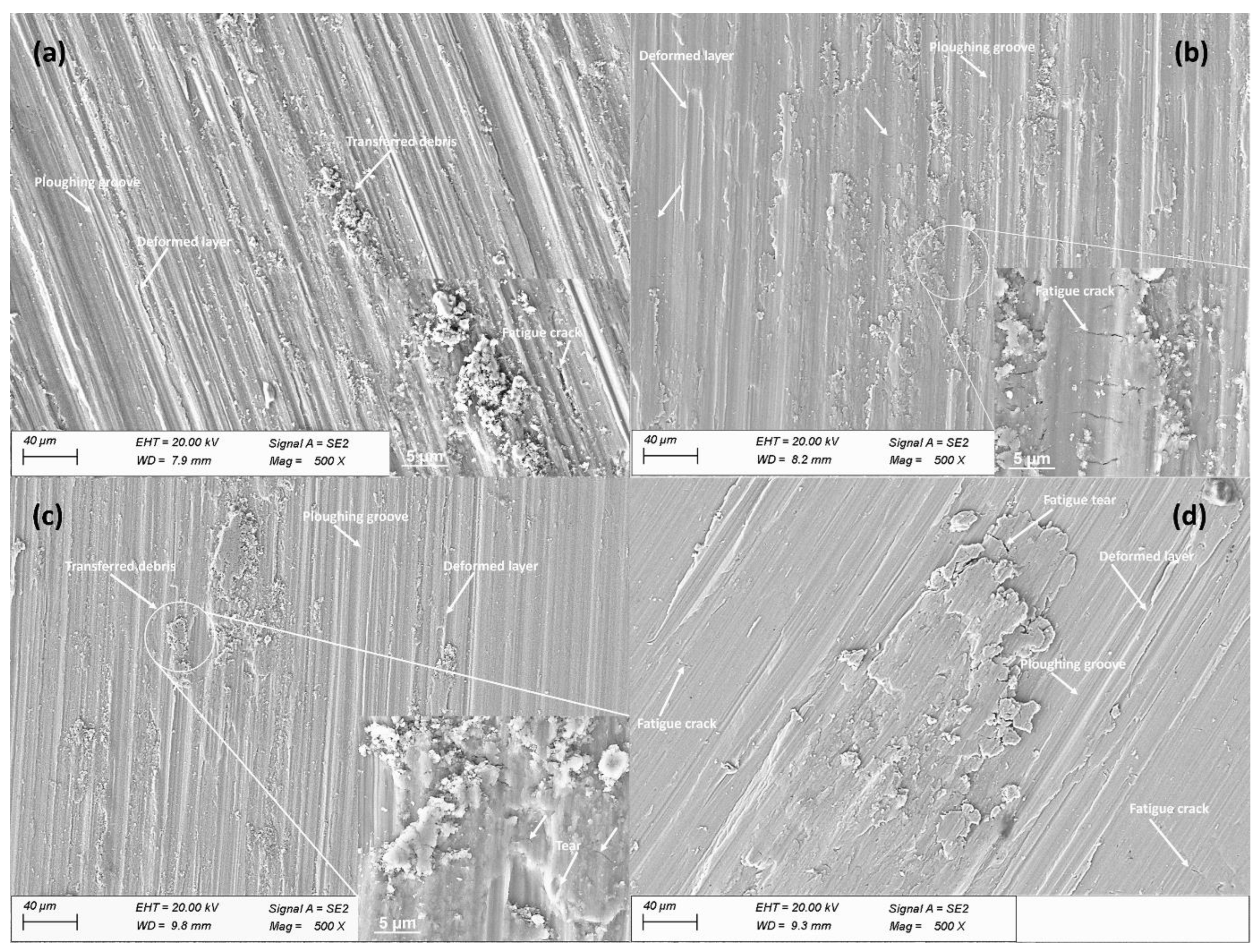
The wear tracks of the samples shown in Figure 11 present features that define the dominant wear regime and mechanism for each of the tested samples. The features shown for each of the tested coating samples reflect the measured properties of the respective coatings as well as the microstructure. Run-1 has the highest specific wear rate as estimated, and its worn surface shows deformed layers, deep plowing grooves, fatigue cracks, and piles of transferred materials. The dominant wear mechanism seems to be plowing given the deep groves that dominate the worn track. Where the materials are not removed, they have undergone plastic deformation; the repeated contacts between the surfaces also subjected the layers to fatigue loading, causing cracks. All the coatings show identical wear mechanisms, but one form is dominant in one compared to others. The height of the plowing grooves reduces from run-1 to run-4; deformed layers dominate the worn track for run-2, with the most distribution of fatigue cracks amongst the samples. The worn rack of run-4 appears to have the shallowest grooves when compared via visual inspection to other worn tracks. The run-4 wear track, however, has large masses of transferred materials across its length, with some randomly distributed fatigue cracks. In any of the cases, none of the coatings showed severe material removal to expose the underlying substrate. Where materials were moved, the transferred materials adhered to the wear track to ensure overall material conservation. This observation suggests the coatings would support the lifespan elongation of a work part coated for repair.
3.2.3. Erosion Wear
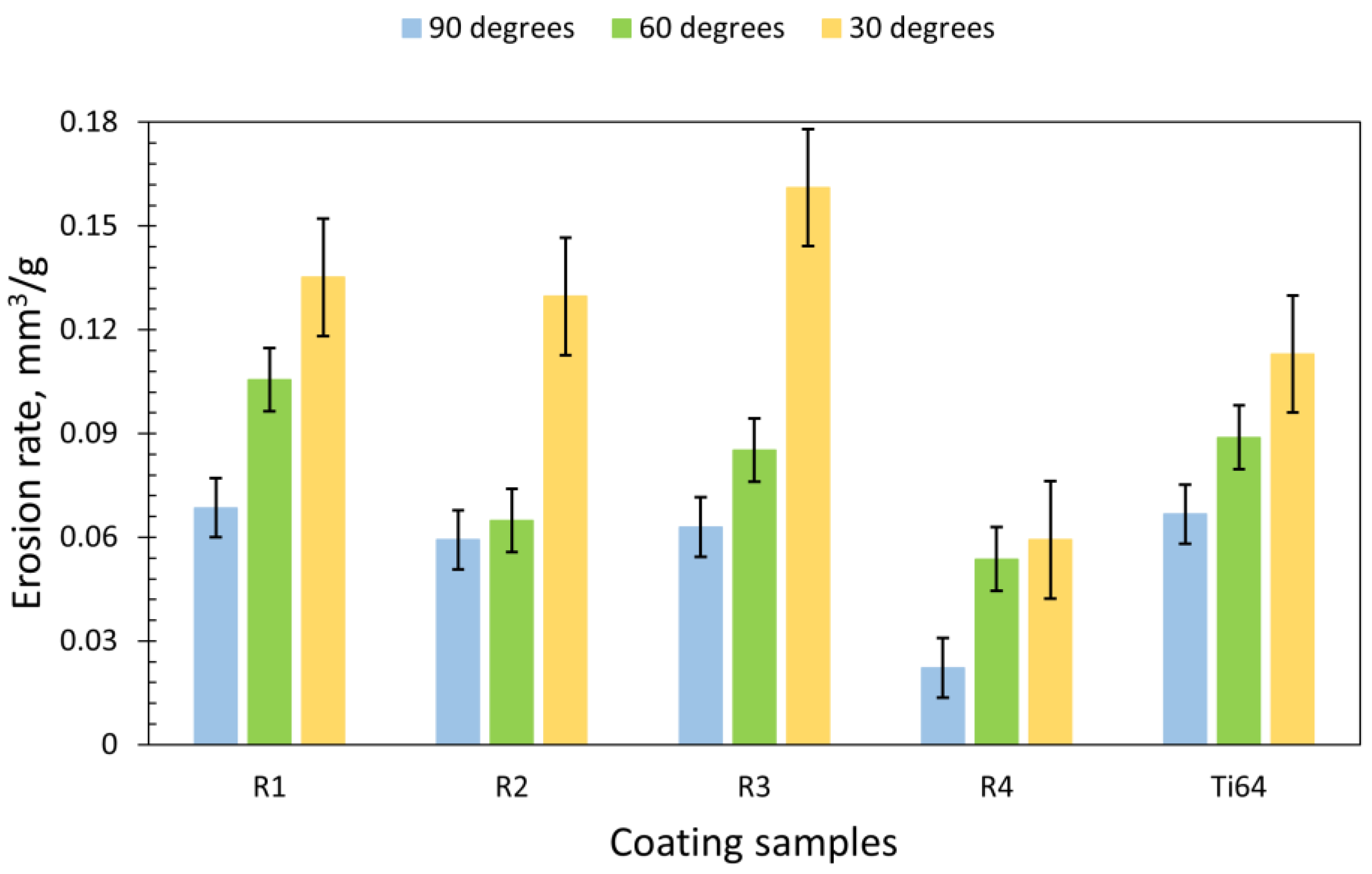
The erosion wear rate of the four coating samples compared to the bulk Ti64 sample is presented in Figure 12. The erodent material has been impinged at the surfaces at three different angles to show the effect of the impingement angle on the erosion rate. In-service conditions of engineering components may expose them to randomly impinging particles. This is particularly true for aeroengine parts operated in sandy environments [27,28]. The contact angle between the impinging erodent particles and the surface of the engineering component is an extrinsic factor to determine the resistance of the impacted surface [29]. Angular particles hitting a surface at an acute angle deliver contact energy sufficient to cause material deformation due to ductility, indents, micro-cracks, or material removal through micro-chipping or plowing, depending on whether the material is ductile or brittle [30]. All the coatings as well as the bulk Ti64 sample show an increased wear rate as the impingement angle goes acute from 90° to 30°. The highest erosion rate is present at the 30° impingement angle for all the tested samples; this is consistent with the observation of previous work on Ti-6Al-4V [29]. However, the least porous of the coating samples, run-4, was expected to mimic the bulk Ti64; it shows superior erosion wear resistance compared to the bulk sample.
The erosion wear response of materials scales with the metallographic makeup of the material, depending on whether the material is ductile or brittle. Ductile materials show a higher erosion wear rate at perpendicular erodent impacts compared to acute angles; brittle materials show the direct opposite of this behaviour [23]. Ductile erosion behaviour is characterized by micro-plowing, cutting, and/or scratching [30]. The mechanisms of wear known with Ti-6Al-4V include plastic deformation, micro-plowing, and micro-scratching [29]. The representative overviews of the impact sites of the erodent particles on the surface of the coatings are shown in Figure 13. The elongated oval geometry created via erodent impacting at 30° suggests a unidirectional flow of material in congruence with the direction of the applied force. The perpendicular impact of the erodent particles hitting at 90° created a circular geometry, while the erodent particles hitting at 60° created a bulged circle.
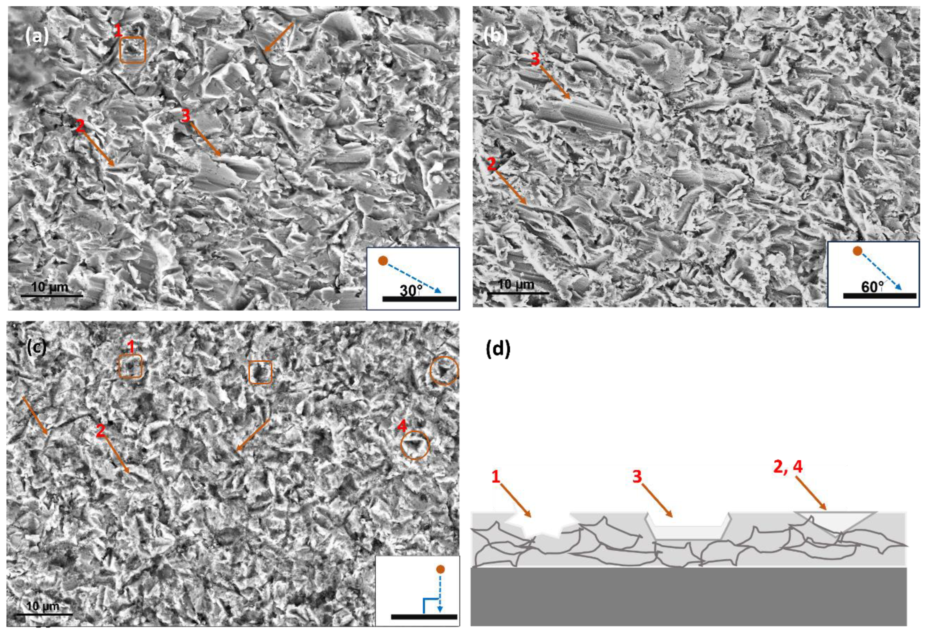
The magnified view of each of the erodent sites was not significantly different for each of the tested samples, coatings, and bulk Ti64 alike. This is despite the observed microstructural build of the respective coatings. The dominant mechanism However, it varies with the angle of impact for the erodent particles, which must have created the characteristic overview for each of the erosion test conditions. Representative micrographs for the three tested impingement angles are shown in Figure 14. The identified mechanisms are marked in addition to a schematic representation for each of the mechanisms. The influence of the two acute angles of impingement (30° and 60°) is shown as the micro-plowing tracks marked “3” and the micro-scratches marked “2”. These two mechanisms dominating the sites as presented corroborate the erosion wear rate results. As a ductile material would show micro-plowing and micro-scratching, such combined features would culminate in an overview of the bulged circle and an elongated oval shape. The perpendicular impingements left diamond-like imprints on the coating surface—see the points marked “4”, Figure 14d. All the mechanisms elicited by the coatings show the retention of the coating material on the substrate, irrespective of the repeated shear stress created at the impact points of the erodent particles. Ti-6Al-4V bulk material is known to show a maximum erosive material removal rate at acute angles [29]. The one closest to a bulk material in terms of microstructure among the four coating samples is run-4. The run-4 coating interestingly shows an improved erosion wear rate compared to the bulk sample. This gives a useful indication of the potential of a dense coating to function well as a repair layer for worn parts. Given the deposition configuration of the run-4 sample, the short nozzle length and short nozzle exit mean the particles have reduced in-flight resident time while exiting at higher temperatures than particles deposited from a wide exit nozzle. This implies the particles only became heated enough to ensure high deformation for a high packing density, as confirmed by their porosity of <5%. This sample therefore has its predominant microstructural features as inter-particle boundaries instead of pores. Grain boundary strengthening is a known mechanism to improve the strength of materials. When the inter-particle boundaries are combined with the strain rate that could have accompanied the particle deposition from the hypersonic speed of the HVAF process, the run-4 sample may have improved strengthening due to grain boundary and work hardening because of the accompanied strain rate of its buildup particles [31]. These strengthening mechanisms may explain the improved erosion resistance of the run-4 sample over the bulk Ti64 sample.
4. Conclusions
This paper presents the HVAF deposition of coatings using commercially sourced Ti-6Al-4V feedstock powder sprayed with different nozzle configurations. The microstructure, sliding wear, and erosion wear of the coatings have been investigated to reach the following conclusions:
- The HVAF technique is capable of depositing Ti-6Al-4V coatings with very high density using an appropriate nozzle configuration;
- The microhardness of the coatings is similar, which correlates with their sliding wear performance;
- The densest of the coatings (<0.5%) compared well with the bulk Ti-6Al-4V material under both sliding and erosive wear conditions and showed improved erosive performance over the bulk Ti-6Al-4V sample;
- The measured properties and the wear performance of the tested coatings are suggestive of the promise of HVAF deposition of Ti-6Al-4V coatings for component repair.
Author Contributions
S.M. and I.C.d.L. conceived and designed the experiments under the supervision of S.J.; S.B. deposited all the coatings used for the study. Primary data collection and analysis (sample preparation, hardness measurement, microstructure (coating thickness and porosity), wear tests, and wear volume loss) were completed by I.C.d.L. and S.M. under the supervision of S.J. The wear track microstructural analysis was completed by T.A.O.; T.A.O. prepared all the Figures as used in the paper as well as completed the original paper draft and the subsequent review and editing, under the supervision of S.J.; S.J. administered the project and secured the project funding. All authors have read and agreed to the published version of the manuscript.
Funding
Financial support from the Swedish funding agency Vinnova for the project DEMAND-Repair (Dnr. 2020-02997), as a part of which the present work was carried out, is gratefully acknowledged.
Institutional Review Board Statement
Not applicable.
Informed Consent Statement
Not applicable.
Data Availability Statement
Data are contained within the article.
Acknowledgments
The authors would like to thank their colleagues at University West, Magnus Sandberg, for their assistance during the spraying of the coatings.
Conflicts of Interest
The authors declare that they have no known competing financial interests or personal relationships that could have appeared to influence the work reported in this paper.
References
- Liu, S.; Shin, Y.C. Additive Manufacturing of Ti6Al4V Alloy: A Review, in Materials and Design; Elsevier: Amsterdam, The Netherlands, 2019. [Google Scholar]
- Browning, J.A. Hypervelocity impact fusion—A technical note. J. Therm. Spray Technol. 1992, 1, 289–292. [Google Scholar] [CrossRef]
- Hussain, T. Cold Spraying of Titanium: A Review of Bonding Mechanisms, Microstructure and Properties. In Key Engineering Materials; Trans Tech Publications, Ltd.: Stafa-Zurich, Switzerland, 2012; pp. 53–90. [Google Scholar]
- Inagaki, I.; Takechi, T.; Ariyasu, Y.S.N. Application and Features of Titanium for the Aerospace Industry. Nippon. Steel Sumitomo Met. Tech. Rep. 2014, 106, 22–27. [Google Scholar]
- Tao, W.; Huapeng, D.; Jie, T.; Hao, W. Recent Repair Technology for Aero-Engine Blades. Recent Pat. Eng. 2015, 9, 132–141. [Google Scholar] [CrossRef]
- Wu, Z.; David, S.A.; Leonard, D.N.; Feng, Z.; Bei, H. Microstructures and mechanical properties of a welded CoCrFeMnNi high-entropy alloy. Sci. Technol. Weld. Join. 2018, 23, 585–595. [Google Scholar] [CrossRef]
- Qin, Y.; Zhang, D.; Jiang, W.; He, X. Microstructure and Mechanical Properties of Welded Joints of Titanium Alloy Ti60 after Laser Welding and Subsequent Heat Treatment. Met. Sci. Heat Treat. 2021, 62, 689–695. [Google Scholar] [CrossRef]
- Davis, J.R. (Ed.) Handbook of Thermal Spray Technology; ASM International: Kinsman Road Materials Park, OH, USA, 2004; p. 332. [Google Scholar]
- Owoseni, T.A.; Bai, M.; Curry, N.; Lester, E.H.; Grant, D.M.; Hussain, T. Residual Stress Measurement of Suspension HVOF-Sprayed Alumina Coating via a Hole-Drilling Method. J. Therm. Spray Technol. 2020, 29, 1339–1350. [Google Scholar] [CrossRef]
- Sadeghimeresht, E.; Hooshyar, H.; Markocsan, N.; Joshi, S.; Nylén, P. Oxidation Behavior of HVAF-Sprayed NiCoCrAlY Coating in H2–H2O Environment. Oxid. Met. 2016, 86, 299–314. [Google Scholar] [CrossRef]
- Björklund, S.; Goel, S.; Joshi, S. Function-dependent coating architectures by hybrid powder-suspension plasma spraying: Injector design, processing, and concept validation. Mater. Des. 2018, 142, 56–65. [Google Scholar] [CrossRef]
- Yasoda, R.D.; Huang, Y.; Kiran, R.; Qi, X. Post-fire Performance of Wire-arc-Sprayed Zn-15Al Coatings. J. Therm. Spray Technol. 2023, 32, 1518–1534. [Google Scholar] [CrossRef]
- Koivuluoto, H. A Review of Thermally Sprayed Polymer Coatings. J. Therm. Spray Technol. 2022, 31, 1750–1764. [Google Scholar] [CrossRef]
- Li, C.J. Thermal Spraying of Light Alloys. In Surface Engineering of Light Alloys; Elsevier: Amsterdam, The Netherlands, 2010; pp. 184–241. [Google Scholar]
- Sundararajan, G.; Prasad, K.U.; Rao, D.S.; Joshi, S.V. A comparative study of tribological behavior of plasma and D-gun sprayed coatings under different wear modes. J. Mater. Eng. Perform. 1998, 7, 343–351. [Google Scholar] [CrossRef]
- Turunen, E.; Varis, T.; Gustafsson, T.E.; Keskinen, J.; Fält, T.; Hannula, S.-P. Parameter optimization of HVOF sprayed nanostructured alumina and alumina–nickel composite coatings. Surf. Coat. Technol. 2006, 200, 4987–4994. [Google Scholar] [CrossRef]
- Eklund, J.; Phother, J.; Sadeghi, E.; Joshi, S.; Liske, J. High-Temperature Corrosion of HVAF-Sprayed Ni-Based Coatings for Boiler Applications. Oxid. Met. 2019, 91, 729–747. [Google Scholar] [CrossRef]
- Lima, R.S.; Marple, B.R. From APS to HVOF spraying of conventional and nanostructured titania feedstock powders: A study on the enhancement of the mechanical properties. Surf. Coat. Technol. 2006, 200, 3428–3437. [Google Scholar] [CrossRef]
- Liu, Y.; Fischer, T.E.; Dent, A. Comparison of HVOF and plasma-sprayed alumina/titania coatings—Microstructure, mechanical properties, and abrasion behavior. Surf. Coat. Technol. 2003, 167, 68–76. [Google Scholar] [CrossRef]
- Xu, Z.; Chen, L.; Shi, X.; Zhang, Q.; Ibrahim, A.M.; Zhai, W.; Yao, J.; Zhu, Q.; Xiao, Y. Formation of Friction Layers in Graphene-Reinforced TiAl Matrix Self-Lubricating Composites. Tribol. Trans. 2015, 58, 668–678. [Google Scholar] [CrossRef]
- Shitole, P.P.; Gawande, S.H.; Desale, G.R.; Nandre, B.D. Effect of Impacting Particle Kinetic Energy on Slurry Erosion Wear. J. Bio- Tribo-Corros. 2015, 1, 29. [Google Scholar] [CrossRef]
- Bolelli, G.; Cannillo, V.; Gadow, R.; Killinger, A.; Lusvarghi, L.; Manfredini, T.; Müller, P. Properties of Al2O3 coatings by High Velocity Suspension Flame Spraying (HVSFS): Effects of injection systems and torch design. Surf. Coat. Technol. 2015, 270, 175–189. [Google Scholar] [CrossRef]
- Gupta, A.; Pattnayak, A.; Abhijith, N.V.; Kumar, D.; Chaudhry, V.; Mohan, S. Development of alumina-based hybrid composite coatings for high temperature erosive and corrosive environments. Ceram. Int. 2023, 49, 862–874. [Google Scholar] [CrossRef]
- Owoseni, T.A.; Romero, A.R.; Pala, Z.; Venturi, F.; Lester, E.H.; Grant, D.M.; Hussain, T. YAG thermal barrier coatings deposited by suspension and solution precursor thermal spray. Ceram. Int. 2021, 47, 23803–23813. [Google Scholar] [CrossRef]
- Ganvir, A.; Curry, N.; Markocsan, N.; Nylén, P.; Toma, F.-L. Comparative study of suspension plasma sprayed, and suspension high velocity oxy-fuel sprayed YSZ thermal barrier coatings. Surf. Coat. Technol. 2015, 268, 70–76. [Google Scholar] [CrossRef]
- Zhang, J.; Alpas, A.T. Transition between mild and severe wear in aluminium alloys. Acta Mater. 1997, 45, 513–528. [Google Scholar] [CrossRef]
- Ma, A.M.; Liu, D.; Zhang, X.; Liu, D.; He, G.; Yin, X. Solid particle erosion behavior and failure mechanism of TiZrN coatings for Ti-6Al-4V alloy. Surf. Coat. Technol. 2021, 426, 127701. [Google Scholar] [CrossRef]
- Shuai, J.T.; Zuo, X.; Wang, Z.; Sun, L.; Chen, R.; Wang, L.; Wang, A.; Ke, P. Erosion behavior and failure mechanism of Ti/TiAlN multilayer coatings eroded by silica sand and glass beads. J. Mater. Sci. Technol. 2021, 80, 179–190. [Google Scholar] [CrossRef]
- Tortuero, S.; Garrido, M.A.; Poza, P.; Rodríguez, J. Evaluating the erosion resistance of Ti6Al4V coatings deposited by cold spray. Wear 2020, 454–455, 203337. [Google Scholar] [CrossRef]
- Alroy, R.J.; Pandey, R.; Kamaraj, M.; Sivakumar, G. Role of process parameters on microstructure, mechanical properties, and erosion performance of HVAF sprayed Cr3C2-NiCr coatings. Surf. Coat. Technol. 2022, 449, 128941. [Google Scholar] [CrossRef]
- Gupta, R.K.; Kumar, V.A.; Mathew, C.; Rao, G.S. Strain hardening of Titanium alloy Ti6Al4V sheets with prior heat treatment and cold working. Mater. Sci. Eng. A 2016, 662, 537–550. [Google Scholar] [CrossRef]
Figure 1.
Application of Ti-6Al-4V in aero engine adapted from [4].
Figure 1.
Application of Ti-6Al-4V in aero engine adapted from [4].

Figure 2.
Ball-on-disk sliding wear configuration adapted from [20].
Figure 2.
Ball-on-disk sliding wear configuration adapted from [20].

Figure 3.
Schematic showing the erosion test configuration adapted from [21].
Figure 3.
Schematic showing the erosion test configuration adapted from [21].

Figure 4.
Ti64 powder feedstock. (a) Secondary electron micrograph. (b) Particle size distribution plot.
Figure 4.
Ti64 powder feedstock. (a) Secondary electron micrograph. (b) Particle size distribution plot.

Figure 5.
Al2O3 erodent powder feedstock. (a) Secondary electron micrograph. (b) Particle size distribution plot.
Figure 5.
Al2O3 erodent powder feedstock. (a) Secondary electron micrograph. (b) Particle size distribution plot.

Figure 6.
BSE micrograph of the cross-sectional images of the coatings deposited with the long nozzle. (a) Wide exit, run-1. (b) Small exit, run-2.
Figure 6.
BSE micrograph of the cross-sectional images of the coatings deposited with the long nozzle. (a) Wide exit, run-1. (b) Small exit, run-2.

Figure 7.
BSE micrograph of the cross-sectional images of the coatings deposited with the short nozzle. (a) Wide exit, run-3. (b) Small exit, run-4.
Figure 7.
BSE micrograph of the cross-sectional images of the coatings deposited with the short nozzle. (a) Wide exit, run-3. (b) Small exit, run-4.

Figure 8.
Secondary electron micrograph of the top surface morphology of the as-sprayed coatings showing (a) micro-crack, (b) blind pore, (c) inter-particle boundary, and (d) buried feedstock particle.
Figure 8.
Secondary electron micrograph of the top surface morphology of the as-sprayed coatings showing (a) micro-crack, (b) blind pore, (c) inter-particle boundary, and (d) buried feedstock particle.

Figure 9.
Vickers hardness value for four coating samples.

Figure 10.
The specific wear rate of coating samples and the bulk Ti64.

Figure 11.
Secondary electron micrograph of wear tracks generated on the surfaces of (a) run-1, (b) run-2, (c) run-3, and (d) run-4, showing grooves, transferred materials, fatigue cracks, and deformed layers.
Figure 11.
Secondary electron micrograph of wear tracks generated on the surfaces of (a) run-1, (b) run-2, (c) run-3, and (d) run-4, showing grooves, transferred materials, fatigue cracks, and deformed layers.

Figure 12.
The erosion wear rate of coating samples and the bulk Ti64 sample.

Figure 13.
Representative SE micrograph showing overviews of erodent impacted sites per incident angle of the erodent to the sample surface: (a) 30°, (b) 60°, and (c) 90°.
Figure 13.
Representative SE micrograph showing overviews of erodent impacted sites per incident angle of the erodent to the sample surface: (a) 30°, (b) 60°, and (c) 90°.

Figure 14.
Representative magnified SE micrographs showing residual imprints eroded surfaces at angles of (a) 30°, (b) 60°, and (c) 90° and a (d) schematic representation of the dominant mechanisms across the three surfaces.
Figure 14.
Representative magnified SE micrographs showing residual imprints eroded surfaces at angles of (a) 30°, (b) 60°, and (c) 90° and a (d) schematic representation of the dominant mechanisms across the three surfaces.


Table 1.
Spray session and nozzle configuration.
| S/N | Spray Sessions | Configurations | |
|---|---|---|---|
| Nozzle Length | Exit Size | ||
| 1. | Run-1 | Long | Wide |
| 2. | Run-2 | Long | Small |
| 3. | Run-3 | Short | Wide |
| 4. | Run-4 | Short | Small |
Table 2.
HVAF spray parameters for the four spray runs are marked by different nozzle types.
| Spray Parameters | Spray Runs | |||
|---|---|---|---|---|
| 1 | 2 | 3 | 4 | |
| Nozzle type | 4L4C | 4L2C | 3L4C | 3L2C |
| Air pressure (MPa) | 0.7 | 0.67 | 0.7 | 0.65 |
| Fuel 1 pressure—propane (MPa) | 0.65 | 0.67 | 0.65 | 0.68 |
| Fuel 2 pressure—propane (MPa) | 0.65 | 0.67 | 0.65 | 0.68 |
| Carrier gas pressure—N2 (l/min) | 40 | 40 | 40 | 40 |
| Feed rate (g/min) | 100 | 100 | 100 | 100 |
| Pass velocity (m/min) | 100 | 100 | 100 | 100 |
| Pass spacing (mm/rev.) | 5 | 5 | 5 | 5 |
| Spray distance (mm) | 200 | 200 | 200 | 200 |
| Number of passes | 10 | 10 | 10 | 10 |
Table 3.
List of estimated porosity and measured thickness of the respective coatings.
| Coating Features | Spray Runs | |||
|---|---|---|---|---|
| 1 | 2 | 3 | 4 | |
| Porosity (%) | 2–3 | 0.5–1 | 1–2 | <0.5 |
| Thickness (mm) | 0.65 | 0.32 | 0.32 | 0.30 |
Disclaimer/Publisher’s Note: The statements, opinions and data contained in all publications are solely those of the individual author(s) and contributor(s) and not of MDPI and/or the editor(s). MDPI and/or the editor(s) disclaim responsibility for any injury to people or property resulting from any ideas, methods, instructions or products referred to in the content. |
© 2023 by the authors. Licensee MDPI, Basel, Switzerland. This article is an open access article distributed under the terms and conditions of the Creative Commons Attribution (CC BY) license (https://creativecommons.org/licenses/by/4.0/).
Share and Cite
MDPI and ACS Style
Owoseni, T.A.; Ciudad de Lara, I.; Mathiyalagan, S.; Björklund, S.; Joshi, S. Microstructure and Tribological Performance of HVAF-Sprayed Ti-6Al-4V Coatings. Coatings 2023, 13, 1952. https://doi.org/10.3390/coatings13111952
AMA Style
Owoseni TA, Ciudad de Lara I, Mathiyalagan S, Björklund S, Joshi S. Microstructure and Tribological Performance of HVAF-Sprayed Ti-6Al-4V Coatings. Coatings. 2023; 13(11):1952. https://doi.org/10.3390/coatings13111952
Chicago/Turabian StyleOwoseni, Tunji A., Irene Ciudad de Lara, Sribalaji Mathiyalagan, Stefan Björklund, and Shrikant Joshi. 2023. "Microstructure and Tribological Performance of HVAF-Sprayed Ti-6Al-4V Coatings" Coatings 13, no. 11: 1952. https://doi.org/10.3390/coatings13111952
Note that from the first issue of 2016, this journal uses article numbers instead of page numbers. See further details here.