
Electrohydrodynamic Printing of PCL@CsPbBr3 Composite Fibers with High Luminescence for Flexible Displays
by
Maolin Liu
1,†,
Changqing Lin
2,†,
Weicheng Ou
1,
Han Wang
1,*,
Chunyang Pan
2,*,
Yuchen Ji
1 and
Hehui Zheng
1 1
Guangdong Provincial Key Laboratory of Micro-Nano Manufacturing Technology and Equipment, The State Key Laboratory of Precision Electronic Manufacturing Technology and Equipment, Guangdong University of Technology, Guangzhou 510006, China
2
School of Light Industry and Chemical Engineering, Guangdong University of Technology, Guangzhou 510006, China
*
Authors to whom correspondence should be addressed.
†
These authors contributed equally to this work.
Coatings 2023, 13(3), 500; https://doi.org/10.3390/coatings13030500
Submission received: 20 January 2023
/
Revised: 16 February 2023
/
Accepted: 18 February 2023
/
Published: 24 February 2023
(This article belongs to the Special Issue Functional Thin Films Growth and Characterization for Opto-Electronic and Renewable Energies Applications)
Abstract
:Metal halide perovskite quantum dots (PQDs) are widely used in the display field due to their excellent photoelectric properties, such as ultra-narrow half-peak widths and ultra-pure luminescence color purity. Inkjet printing, laser direct writing and electrospinning are all common methods for PQDs printing to prepare micropattern displays. In order to produce large-scale and high-resolution PQDs micropatterns, electrohydrodynamic (EHD) printing technology is capable of large-scale deposition of highly oriented nanofibers on rigid or pliable, flat or bent substrates with the advantages of real-time regulation and single control. Therefore, it has a lot of potential in the fabrication of pliable electronic devices for one-dimensional ordered light-emitting fibers. Polycaprolactone (PCL) as an EHD printing technology polymer material has the advantages of superior biocompatibility, a low melting point, saving energy and easy degradation. By synthesizing CsPbBr3 quantum dots (QDs) and PCL composite spinning stock solution, we used the self-built EHD printing platform to prepare the PCL@CsPbBr3 composite light-emitting optical fiber and realized the flexible display of high-resolution micropatterns in polydimethylsiloxane (PDMS) packaging. An x-ray diffractometer (XRD), scanning electron microscope (SEM) and photoluminescence (PL) were used to characterize and analyze the fiber’s morphology, phase and spectral characteristics. EHD printing technology may open up interesting possibilities for flexible display applications based on metal halide PQDs.
1. Introduction
Recently, flexible electronic display products have emerged as one of the most significant next-generation consumer products due to their superior flexibility, foldability, bendability and stretchability, which cater to a wide variety of viewing conditions [1,2]. In response to this emerging demand, numerous research efforts have been made and various stretchable optoelectronic devices [3] have been developed, such as light-emitting diodes (LEDs), solar cells [4], field-effect transistors and memory devices [5]. Smartphones, wearable electronics and mobile electronics could be developed using stretchable devices in the future [6,7]. All-inorganic cesium lead halide perovskite has the advantages of a long diffusion length, long carrier life, super-smooth surface, high refractive index and low defect density. This new type of semiconductor material has a broad range of applications in the fields of photovoltaics and optoelectronics [8,9,10]. All-inorganic cesium lead halide perovskites (CsPbX3, X = Cl, Br, I) have been shown to be highly luminescent, with narrow emission linewidths, high chromatogram purity and a wide range of emission wavelengths across all visible regions [11,12,13]. It can be widely used in the field of flexible photoelectric displays.
Nevertheless, the intrinsic ionic nature of inorganic perovskites and low formation energy (≈0.1–0.3 eV) make the crystal structure of perovskite materials very sensitive to moisture, polar solvents and air [14,15]. It is unavoidable that perovskite crystals remain unsatisfactory in terms of stability [15,16]. Disperse nanocrystals in different protective matrices can improve stability [17]. To protect perovskites from water and air, mesoporous inorganic materials (such as SiO2, TiO2 and Al2O3) have been reported to form core-shell nanocomposites [18,19]. Mesoporous structures, on the other hand, expose these materials to ambient air [20]. In recent years, coating technologies have been developed to passivate nanocrystals (NCs) using compact polymer matrixes, enabling them to be more chemically stable, particularly by confining them in 1D polymer nanofibers through EHD printing technology [21,22]. EHD printing technology is capable of the large-scale deposition of highly oriented nanofibers on rigid or pliable, flat or bent substrates with real-time regulation and single control. Therefore, it has considerable potential in the fabrication of pliable electronic devices for one-dimensional ordered light-emitting fibers [23]. Taking the presynthesized PQDs as the support, the nano-crystal was incorporated into the polymethylmethacrylate (PMMA) fiber matrix using uniaxial technology and an ultra-sensitive sensor was constructed [24]. A uniform polymer matrix can embed luminescent perovskite nanoparticles (NPs) with appreciable stretchability. In order to demonstrate this fundamental principle, stretchable and luminescent perovskite nanofibers have been developed [25]. On the one hand, perovskite NPs can be grown in polymer templates (or matrices) by taking advantage of their chemical interactions [26,27]; on the other hand, the electrospinning technique imparts a uniform distribution of perovskite nanoparticles through fabricated nanofibers, as demonstrated in our recent work [28,29,30,31,32,33].
We successfully prepared uniformly luminescent PCL@CsPbBr3 composite fibers using the EHD printing technique and demonstrated that PQDs still have bright green luminescence and water stability under the encapsulation of PCL polymer. It remains a significant challenge, however, to achieve multicolor quantum dot composite nanofiber flexible display screens. Therefore, we propose the preparation of hybrid inorganic-based stretchable green light-producing nanofibers in which an organic light-producing polymer serves as the shell. It is also necessary to develop innovative methods for tuning the emission color of nanofiber-integrated flexible display devices. By preparing stable and elastic light-emitting nanofibers and integrating such nanofibers into flexible and wearable light-emitting devices, our work provides an effective method for achieving the desired emission color.
2. Materials and Methods
2.1. Materials
Oleic acid (OA, AR), oleylamine (OAm, 80%–90%), 1-octadecene (ODE, 90%), cesium carbonate (Cs2CO3, 99.99%) and lead bromide (PbBr2, 99.9%) were purchased from Aladdin (Shanghai, China). n-hexane (AR) was obtained from Sinopharm Chemical Reagent (Shanghai, China). All chemicals were used directly without any further purification.
2.2. Methods
2.2.1. Synthesis of Cs-Oleate
In a 100 mL round-bottom flask, Cs2CO3 (0.05 g), OA (0.5 mL) and ODE (10 mL) were mixed. To completely remove moisture and oxygen, the mixture was heated at 110 °C for 1 h under a vacuum. Following this, all Cs2CO3 reacted with OA under N2 atmosphere at 120 °C until Cs-oleate was formed.
2.2.2. Synthesis of CsPbBr3 PQDs
The synthesis method of CsPbBr3 PQDs is similar to the approach of MC Jiang [34] et al. Several minor modifications were made. We prepared a 250 mL three-necked round-bottomed flask, added 10 mL ODE and 0.2 mmol PbBr2 and dried them under a vacuum of 110 °C and 133 Pa for 1 h, N2 was used to purge the flask and then OA and OAm were injected into it at 70 °C after they were preheated. PbBr2 and OA and OAm were heated to 120 °C until completely reacted. Once the temperature reached 150 °C, Pb-oleate was rapidly injected with the Cs-oleate precursor (0.8 mL). The solution was maintained at 150 °C for several seconds to allow the growth of the PQDs. The solution was cooled by soaking the flask in a cold-water bath.
2.2.3. Purification
In order to precipitate the CsPbBr3 PQDs, the sample was spun for five minutes at 6000 rpm. Vortexing hexane (1.5 mL) with the precipitate made the colored supernatant be discarded. Five minutes were spent centrifuging the solution at 6000 rpm. To remove agglomerations, excess Cs-oleate and larger PQDs, the PQDs were dispersed in hexane (1 mL) and centrifuged for two minutes at 10,000 rpm. CsPbBr3 PQDs were dispersed colloidally in hexane after the precipitate was collected and redispersed.
2.2.4. Synthesis of PCL@CsPbBr3
The PCL@CsPbBr3 composite was prepared as follows. Take 1 g of polycaprolactone and 1 mL of toluene in a 25 mL small beaker, heat and stir at 80 °C for 30 min and then let it stand at room temperature. Take 1 mL of CsPbBr3 PQDs that have just been centrifuged and scattered, add this to the melted PCL and stir at room temperature for five minutes to form a stable and transparent yellow PCL@CsPbBr3 solution.
2.2.5. Preparation of Composite Fiber
Composite fibers were prepared using a built-up EHD printing device. As shown in Figure 1a, the spinning raw material was injected into a syringe with a needle and the voltage was adjusted to 1.25 kV, the distance between the needle and the collection plate was 2 mm, the heating temperature was 95 °C and the air pressure was 0.2 KPa. The Taylor cone is an important criterion for fiber molding and the appearance of a Taylor cone at the needle (Figure 1b) was observed in a high-resolution camera, followed by the formation of fine, controllable fiber deposits at the needle under the action of voltage. Set the platform movement speed to 5 mm/s, 10 mm/s and 15 mm/s for printing trajectory. Ordered deposition and stacking of fibers were observed in the camera (Figure 1c) and emitted high-brightness green light by illuminating the grid with an ultraviolet lamp (Figure 1d).
2.2.6. High-Resolution Pattern Printing
Composite fibers with a diameter of 10 μm were successfully prepared by EHD printing technology and high-resolution patterns were successfully printed by motion trajectory control. This is shown in Figure 2; we first realized the simple pattern printing (a, b) of straight-line connection through trajectory control, then we tried to print the pattern under the complex path (c) by designing the corresponding curve, polyline and other trajectories, and the printed pattern emits high-brightness green light (d, e, f) under ultraviolet light.
2.2.7. Flexible Display Applications
In order to better display the mechanical properties and photoluminescence characteristics of fibers, we stacked 15 layers of fibers, used polydimethylsiloxane (PDMS) as a flexible substrate to transfer and package the optical fibers and successfully obtained a flexible display device based on QDs luminescent fiber. As shown in Figure 3, PDMS was used as a flexible substrate to encapsulate light-emitting fibers. The composite fiber collection plate was placed on a plane (a) and the prepolymer and crosslinker of PDMS (SYLGARD 184) were fully mixed with a mass ratio of 10:1 to prepare liquid PDMS. The liquid PDMS was then poured onto the glass collection plate (b) until the liquid PDMS had completely passed the sample. The entire sample was placed in a vacuum drying oven and kept warm at 50 °C for 60 min to allow the PDMS to be completely cured. The solidified PDMS and the fiber sample were removed from the glass plate together (c) and the resulting composite was placed in reverse and pouring was repeated to obtain the encapsulation of the PDMS and the fiber sample (f). PDMS had a good transparency effect (g) and the light-emitting fibers were stably embedded in the PDMS substrate (h, i).
2.2.8. Analytical Methods
The X-ray diffraction (XRD) diagram was recorded on the D8 Advance X-ray diffractometer (Bruker AXS, Karlsruhe, Germany) with a voltage of 40 kV, current of 30 mA and copper radiation. The sample was scanned at room temperature at a scanning speed of 4 °/min within the scanning angle range of 10 to 70°.
TEM images were obtained using high-resolution transmission electron microscopy (HR-TEM, FEI Tecnai20, Hitachi, Tokyo, Japan). The lattice constant was determined from the HR-TEM images using GATAN software DigitalMicrograph 3.5.
The absorption spectra were obtained using a UV–Vis spectrophotometer (Varian, Cary 50, Shimadzu, Kyoto, Japan).
PL excitation and emission spectra were measured using a steady-state spectrofluorometer (PTI, Quanta Master, Horiba, Kyoto, Japan) with an excitation wavelength of 360 nm.
The fluorescence spectrum was measured with an FLS 980 spectrophotometer (Jobin Yvon, Austin, TX, USA) and the slit width was 0.5 nm. The fluorescence life was measured with an FLS 980 spectrophotometer.
In order to observe the distribution of quantum dot (QD) luminescent materials in the fiber-forming polymer matrix, SEM (TM3030, Hitachi, Shanghai, China) images were used to observe the microscopic morphology of perovskite quantum dot luminescent materials and the transverse and longitudinal structures of luminescent fibers at 20 kV accelerating voltage. All samples were dried and coated with gold before scanning.
Under standard atmospheric conditions, use a CMT2502 fiber electronic tensile testing machine (SSTJ, Zhuhai, China, clamping length: 6 mm, tensile speed: 5 mm/min, sample size: 0.5 mm × 0.12 mm) to test the breaking strength and elongation of the sample.
3. Results and Discussion
3.1. XRD Phase Analysis
In order to characterize the structural crystal forms of the materials, Figure 4 shows the XRD spectra of CsPbBr3, polymer PCL and PCL@CsPbBr3 composites. Typical characteristic peaks of PCL appear at 2𝜃 = 21.6° and 23.8°, which corresponds to (110) and (200) crystal planes [35]. It can be clearly seen that the prepared CsPbBr3 has peaks at 15.2°, 22.1°, 26.4°, 30.5°, 34.3°, 38.2°,43.7°, 46.4°, 49.4°, 54.3° and 59.1°, which correspond to (100), (110), (111), (200), (210), (211), (220), (300), (310), (222) and (321) crystal planes. It was basically the same as the standard card consistent (PDF#04-005-6613). They all show sharp peaks, meaning that the PQDs have good crystallinity. We obtained a consistent result with our TEM results. Further, it can be observed that PCL has two distinct main characteristic peaks located at 23.3° and 24.1°. These two peaks also appear in the composite material we prepared, corresponding to CsPbBr3 and PCL, respectively, which proves that we successfully prepared PCL@CsPbBr3 composite material.
3.2. TEM Morphological Analysis
The TEM images shown in Figure 5a indicate that CsPbBr3 has a good cubic morphology and monodisperse distribution. From Figure 5b, we can see that the size distribution of the prepared PQDs CsPbBr3 is around 11.5 nm. A high-resolution TEM (HRTEM) image of CsPbBr3 NCs, as shown in Figure 5c, shows clear lattice fringes indicating good crystallinity of these NCs. More importantly, it shows the lattice spacing is about 5.874 Å nm in the (211) direction, which is consistent with the XRD standard card. The PQDs with good dispersion are beneficial to the distribution in the composite material, making the emitted monochromatic light pure. Figure 5d,e are the HRTEM images of the CsPbBr3 nanostructures synthesized. It can be observed that CsPbBr3 nanostructures are arranged neatly in a non-polar solvent and most of them appear as cube-shaped CsPbBr3 nanocrystals. As shown in Figure 5f–i, energy dispersive x-ray spectroscopy (EDX) was performed for typical CsPbBr3 PQDs. The elements Cs, Pb and Br were identified in CsPbBr3 PQDs. The three target elements were evenly distributed throughout the selection region, indicating a successful synthesis of CsPbBr3 PQDs.
3.3. Optical and Surface Performance Analysis
To study the CsPbBr3 and PCL@CsPbBr3 optical properties of composite fibers, we conducted PL and UV-Vis tests. As seen in Figure 6a, they showed significant differences under the irradiation of a 365 nm ultraviolet lamp. It is worth noting that the CsPbBr3 and PCL@CsPbBr3 fluorescence emission peaks are 525 nm and 528 nm. Compared to pure CsPbBr3 NCs (emission peak centered at 525 nm, Figure 6a), a 3 nm red shift occurs due to the presence of the polymer. In any case, the difference in the PL peak wavelength is significantly smaller than the one observed in the exciton absorbance. On the other hand, the shape of the emission bands of the nanocomposites is similar to that of CsPbBr3 in solution. This fact indicates that the NCs embedded in the polymer matrix are well-dispersed with no aggregation [36]. In addition, Figure 6b shows that the CsPbBr3 and PCL@CsPbBr3 UV absorption peaks are 502 nm and 503 nm, respectively. In order to clarify the luminescence range and wetting effect of the composite material PCL@CsPbBr3, we tested its contact angle. As shown in Figure 6c,d, we measured the contact angle several times and made statistics. The average contact angle between the droplet of PCL@CsPbBr3 and the glass substrate is 106.9°, which indicates that the composite material we prepared has hydrophobic properties.
3.4. Water Stability Test
To study CsPbBr3 and PCL@CsPbBr3 water stability, as shown in Figure 7a, 3 mL CsPbBr3 QDs were placed in a glass bottle filled with 10 mL of water for 1 h. It can be clearly seen that the color brightness of the bright green PQDs composite decreases after 1 h in water. The PL in Figure 7b shows that the fluorescence intensity decreases by 50% after 24 h and the QDs fluorescence intensity is close to 0. However, as shown in Figure 7c, 3 mL PCL@CsPbBr3 was put in a glass bottle containing 10 mL water for 24 h, after which it was obvious that the color brightness of the bright green PQDs composite decreased slowly after 24 h in water. It can be seen from Figure 7d that the PCL@CsPbBr3 fluorescence intensity decreases by only 30%. Therefore, PCL@CsPbBr3 is more stable than CsPbBr3 QDs. This is because of the dense shell of the polymer, which can prevent moisture from entering and damaging the QDs structure for a long time [37].
3.5. Structure and Morphology Analysis of PCL@CsPbBr3 Composite Fiber
Figure 8a–c are the images of composite luminous fibers under a scanning electron microscope (SEM) at different platform speeds. It can be seen from Figure 8 that the luminous fibers prepared based on the EHD printing technology of the current have good morphology, high length—diameter ratio, good dispersion, uniform size distribution, a smooth surface, an orderly arrangement and grid-like alternating stacking. Figure 8d–f show that the fiber diameter decreases with the increase of platform motion speed. When the moving speed is 5 mm/s, the fiber diameter is 11~15 μm; when the speed is 10 mm/s, the average diameter of the optical fiber is 8~11 μm; when the speed is 15 mm/s, the average diameter of the optical fiber is 1~7 μm and there are obvious discontinuities and uneven diameter distribution. By comparing the average diameter (AD) and the standard deviation (SD), the optimal speed for fiber molding is determined to be 10 mm/s.
3.6. Mechanical Properties Analysis
Figure 9 shows the stress—strain curve of PCL@CsPbBr3 composite fibers (fibers stacked with 10 layers). It can be seen from the figure that the tensile strength of the PCL@CsPbBr3 composite fiber is 8.91 MPa and the elongation at break is about 153%. As a result, the PCL@CsPbBr3 composite fiber has high plasticity and toughness. This excellent mechanical property is suitable for bending, stretching, extrusion and other applications in flexible display devices.
4. Conclusions
We have successfully prepared PCL@CsPbBr3 composite fibers using EHD printing technology. By comparing and analyzing the fiber morphology at three different speeds, 10 mm/s was determined to be the optimal traction speed, which improves the preparation success rate and fiber quality. The crystal structure of CsPbBr3 distributed in the optical fiber dimension was analyzed by XRD and TEM. It was not affected by the polymer matrix or manufacturing process, which ensured excellent luminescence performance. The PL test shows that the prepared samples show an obvious green emission peak at 528 nm in response to 365 nm UV light, which showed good luminescence characteristics. The contact angle tests showed that PCL polymers adhere to the surface of CsPbBr3 and have strong hydrophobic properties. The tensile test showed that composite fibers have high tensile strength and tensile deformation; we also proved that PQDs still have bright green luminescence and water stability under the encapsulation of PCL polymer. Due to their excellent mechanical properties, orderly deposition and ease of patterning, composite fibers are likely to be used in flexible displays, anti-counterfeit products and photoelectric sensors.
Author Contributions
M.L.: writing—original draft, formal analysis, investigation and visualization. C.L.: writing—original draft, formal analysis, investigation and supervision. W.O.: writing—reviewing and editing, investigation. H.W.: writing—reviewing and editing, investigation. C.P.: writing—reviewing and editing, investigation. H.Z.: writing—reviewing and editing, investigation. Y.J.: conceptualization, methodology. All authors have read and agreed to the published version of the manuscript.
Funding
This work has been supported by the Guangdong Jihua Laboratory Foundation Project (X190071UZ190), the National Natural Science Foundation of China (62171142), and the Guangdong Natural Science Foundation (No. 2314050003244).
Institutional Review Board Statement
This article does not contain any studies with human participants or animals performed by any of the authors.
Informed Consent Statement
Not applicable.
Data Availability Statement
Not applicable.
Conflicts of Interest
The authors declare no conflict of interest.
References
- Zhao, Z.; Liu, K.; Liu, Y.; Guo, Y.; Liu, Y. Intrinsically flexible displays: Key materials and devices. Natl. Sci. Rev. 2022, 9, nwac090. [Google Scholar] [CrossRef] [PubMed]
- Yan, K.; Li, J.; Pan, L.; Shi, Y. Inkjet printing for flexible and wearable electronics. APL Mater. 2020, 8, 120705. [Google Scholar] [CrossRef]
- Wang, J.; Lee, P. Progress and Prospects in Stretchable Electroluminescent Devices. Nanophotonics 2017, 6, 435–451. [Google Scholar] [CrossRef] [Green Version]
- Yelzhanova, Z.; Nigmetova, G.; Aidarkhanov, D.; Daniyar, B.; Baptayev, B.; Balanay, M.P.; Jumabekov, A.N.; Ng, A. A morphological study of solvothermally grown SnO2 nanostructures for application in perovskite solar cells. Nanomaterials 2022, 12, 1686. [Google Scholar] [CrossRef] [PubMed]
- Zhao, J.; Chi, Z.; Yang, Z.; Chen, X.; Arnold, M.S.; Zhang, Y.; Xu, J.; Chi, Z.; Aldred, M.P. Recent developments of truly stretchable thin film electronic and optoelectronic devices. Nanoscale 2018, 10, 5764–5792. [Google Scholar] [CrossRef] [PubMed]
- Kong, W.-W.; Zhou, C.-G.; Dai, K.; Jia, L.-C.; Yan, D.-X.; Li, Z.-M. Highly stretchable and durable fibrous strain sensor with growth ring-like spiral structure for wearable electronics. Compos. Part B Eng. 2021, 225, 109275. [Google Scholar] [CrossRef]
- Wang, B.; Thukral, A.; Xie, Z.; Liu, L.; Zhang, X.; Huang, W.; Yu, X.; Yu, C.; Marks, T.J.; Facchetti, A. Flexible and stretchable metal oxide nanofiber networks for multimodal and monolithically integrated wearable electronics. Nat. Commun. 2020, 11, 2405. [Google Scholar] [CrossRef] [PubMed]
- Zhang, M.; Zheng, Z.; Fu, Q.; Chen, Z.; He, J.; Zhang, S.; Yan, L.; Hu, Y.; Luo, W. Growth and characterization of all-inorganic lead halide perovskite semiconductor CsPbBr3 single crystals. CrystEngComm 2017, 19, 6797–6803. [Google Scholar] [CrossRef]
- Lin, Y.; Zheng, X.; Shangguan, Z.; Chen, G.; Huang, W.; Guo, W.; Fan, X.; Yang, X.; Zhao, Z.; Wu, T.; et al. All-inorganic encapsulation for remarkably stable cesium lead halide perovskite nanocrystals: Toward full-color display applications. J. Mater. Chem. C 2021, 9, 12303–12313. [Google Scholar] [CrossRef]
- Liao, M.; Shan, B.; Li, M. In situ Raman spectroscopic studies of thermal stability of all-inorganic cesium lead halide (CsPbX3, X = Cl, Br, I) perovskite nanocrystals. J. Phys. Chem. Lett. 2019, 10, 1217–1225. [Google Scholar] [CrossRef] [PubMed]
- Cheng, D.; Yang, Z.; Liang, Y. Preparation and Energy Storage Performance of Perovskite Luminescent Materials by an Electrochemiluminescence Method. Adsorpt. Sci. Technol. 2022, 2022, 3092941. [Google Scholar]
- Zhou, R.; Cheng, C.; Wang, X.; Nie, K.; Wu, J.; Wu, M.; Duan, X.; Hu, Z.; Huq; Wang, H.; et al. Metal halide perovskite nanocrystals with enhanced photoluminescence and stability toward anti-counterfeiting high-performance flexible fibers. Nano Res. 2022, 16, 3542–3551. [Google Scholar] [CrossRef]
- Zhang, L.; Zhang, Y.; He, W.; Peng, H.; Dai, Q. CsPbBr3 perovskite nanowires and their optical properties. Opt. Mater. 2020, 109, 110399. [Google Scholar] [CrossRef]
- Wang, Z.; Zhang, J.; Guo, W.; Xiang, W.; Hagfeldt, A. Formation and Stabilization of Inorganic Halide Perovskites for Photovoltaics. Matter 2021, 4, 528–551. [Google Scholar] [CrossRef]
- Zhao, C.; Li, Y.; Ye, W.; Shen, X.; Wen, Z.; Yuan, X.; Cao, Y.; Ma, C. Ligand-Free CsPbBr3 Perovskite Quantum Dots in Silica-Aerogel Composites with Enhanced Stability for w-LED and Display by Substituting Pb2+ with Pr3+ or Gd3+ Ions. Adv. Opt. Mater. 2022, 10, 2102200. [Google Scholar] [CrossRef]
- Meyns, M.; Peralvarez, M.; Jungemann, A.H.; Hertog, W.; Lbanez, M.; Nafria, R.; Genc, A.; Arbiol, J.; Kovalenko, M.V.; Carreras, J.; et al. Polymer-Enhanced Stability of Inorganic Perovskite Nanocrystals and Their Application in Color Conversion LEDs. ACS Appl. Mater. Interfaces 2016, 8, 19579–19586. [Google Scholar] [CrossRef] [Green Version]
- Demkiv, T.M.; Myagkota, S.V.; Malyi, T.; Pushak, A.S.; Vistovskyy, V.V.; Yakibchuk, P.M.; Shapoval, O.V.; Mitina, N.E.; Zaichenko, A.S.; Voloshinovskii, A.S. Luminescence properties of CsPbBr3 nanocrystals dispersed in a polymer matrix. J. Lumin. 2018, 198, 103–107. [Google Scholar] [CrossRef]
- Li, H.; Zhang, B.; Zhang, B.; Bala, H.; An, X.; Sha, N.; Sun, Z.; Zhang, W.; Zhang, Z. Core-shell structuredCsPbBr3/Sn-TiO2 nanocrystals for visible-light-driven photocatalyst in aqueous solution. Appl. Surf. Sci. 2022, 599, 153937. [Google Scholar] [CrossRef]
- Kar, M.R.; Ray, S.; Patra, B.K.; Bhaumik, S. State of the art and prospects of metal halide perovskite core@shell nanocrystals and nanocomposites. Mater. Today Chem. 2021, 20, 100424. [Google Scholar] [CrossRef]
- Numata, Y.; Sanehira, Y.; Miyasaka, T. Impacts of heterogeneous TiO2 and Al2O3 composite mesoporous scaffold on formamidinium lead trihalide perovskite solar cells. ACS Appl. Mater. Interfaces 2016, 8, 4608–4615. [Google Scholar] [CrossRef]
- Li, Q.F.; Wang, J.T.; Tian, B.; Kong, S.; Wang, T.; Wang, Z. Hybridization of CsPbBr3 perovskite nanocrystals with polymer nanofiber to improve their luminescence stability. Eur. J. Inorg. Chem. 2018, 2018, 4215–4220. [Google Scholar] [CrossRef]
- Hu, X.; Xu, Y.; Wang, J.; Ma, J.; Wang, L.; Jiang, W. In Situ Fabrication of Superfine Perovskite Composite Nanofibers with Ultrahigh Stability by One-Step Electrospinning Toward White Light-Emitting Diode. Adv. Fiber Mater. 2022, 5, 183–197. [Google Scholar] [CrossRef]
- Ye, D.; Ding, Y.; Duan, Y.; Su, J.; Yin, Z.; Huang, Y.A. Large-Scale Direct-Writing of Aligned Nanofibers for Flexible Electronics. Nano Micro 2018, 14, 1703521. [Google Scholar] [CrossRef]
- Qaid, S.M.; Ghaithan, H.M.; AlHarbi, K.K.; AI-Asbahi, B.A.; Aldwayyan, A.S. Enhancement of light amplification of CsPbBr3 perovskite quantum dot films via surface encapsulation by PMMA polymer. Polymers 2021, 13, 2574. [Google Scholar] [CrossRef] [PubMed]
- Ercan, E.; Tsai, P.C.; Chen, J.Y.; Lam, J.Y.; Hsu, L.C.; Chueh, C.C.; Chen, W.C. Stretchable and Ambient Stable Perovskite/Polymer Luminous Hybrid Nanofibers of Multicolor Fiber Mats and Their White LED Applications. ACS Appl. Mater. Interfaces 2019, 11, 23605–23615. [Google Scholar] [CrossRef] [PubMed]
- Shen, J.; Wang, Y.; Zhu, Y.; Gong, Y.; Li, C. A polymer-coated template-confinement CsPbBr3 perovskite quantum dot composite. Nanoscale 2021, 13, 6586–6591. [Google Scholar] [CrossRef] [PubMed]
- Kim, H.; So, S.; Ribbe, A.; Liu, Y.; Hu, W.; Duzhko, V.V.; Hayward, R.C.; Emrick, T. Functional polymers for growth and stabilization of CsPbBr3 perovskite nanoparticles. Chem. Commun. 2019, 55, 1833–1836. [Google Scholar] [CrossRef]
- Ren, Y.; Wang, S.; Liu, R.; Dai, J.; Liu, X.; Yu, J. A novel route towards well-dispersed short nanofibers and nanoparticles via electrospinning. RSC Adv. 2016, 6, 30139–30147. [Google Scholar] [CrossRef]
- Bi, H.; Liu, F.; Wang, M.; Mao, Z.; Zhai, Y.; Li, W.; Wang, S.; Zhang, M. Construction of ultra-stable perovskite-polymer fibre membranes by electrospinning technology and its application to light-emitting diodes. Polym. Int. 2021, 70, 90–95. [Google Scholar] [CrossRef]
- Xiong, J.; Wang, H.; Lan, X.; Wang, Y.; Wang, Z.; Bai, J.; Ou, W.; Cai, N.; Wang, W.; Tang, Y. Fabrication of bioinspired grid-crimp micropatterns by melt electrospinning writing for bone–ligament interface study. Biofabrication 2022, 14, 025008. [Google Scholar] [CrossRef]
- Pidluzhna, A.; Lvaniuk, K.; Stakhira, P.; Hotra, Z.; Chapran, M.; Ulanski, J.; Tynkevych, O.; Khalavka, Y.; Baryshnikov, G.V.; Minaev, B.F.; et al. Multi-channel electroluminescence of CdTe/CdS core-shell quantum dots implemented into a QLED device. Dye. Pigment. 2019, 162, 647–653. [Google Scholar] [CrossRef]
- Jiang, D.-H.; Tsal, Y.-H.; Veeramuthu, L.; Liang, F.-C.; Chen, L.-C.; Lin, C.C.; Satoh, T.; Tung, S.-H.; Kuo, C.-C. Novel ultra-stable and highly luminescent white light-emitting diodes from perovskite quantum dots—Polymer nanofibers through biaxial electrospinning. APL Mater. 2019, 7, 111105. [Google Scholar] [CrossRef]
- Ivaniuk, K.; Cherpak, V.; Stakhira, P.; Baryshnikov, G.; Minaev, B.; Hotra, Z.; Turyk, P.; Zhydachevskii, Y.; Volyniuk, D.; Aksimentyeva, O.; et al. BaZrO3 perovskite nanoparticles as emissive material for organic/inorganic hybrid light-emitting diodes. Dye. Pigment. 2017, 145, 399–403. [Google Scholar] [CrossRef] [Green Version]
- Jiang, M.-C.; Pan, C.-Y. Research on the stability of luminescence of CsPbBr3 and Mn: CsPbBr3 PQDs in polar solution. RSC Adv. 2022, 12, 15420–15426. [Google Scholar] [CrossRef] [PubMed]
- Bhattarai, N.; Li, Z.; Cunn, J.; Leung, M.; Cooper, A.; Edmondson, D.; Veiseh, O.; Chen, M.-H.; Zhang, Y.; Ellenbogen, R.G.; et al. Natural-synthetic polyblend nanofibers for biomedical applications. Adv. Mater. 2009, 21, 2792–2797. [Google Scholar] [CrossRef]
- Aznar-Gadea, E.; Sanchez-Alarcon, I.; Soosaimanickam, A.; Rodriguez-Canto, P.; Perez-Pla, F.; Martinez-Pastor, J.; Abargues, R. Molecularly imprinted nanocomposites of CsPbBr3 nanocrystals: An approach towards fast and selective gas sensing of explosive taggants. J. Mater. Chem. C 2022, 10, 1754–1766. [Google Scholar] [CrossRef]
- Kang, G.; Lee, H.; Moon, J.; Jang, H.-S.; Cho, D.-S.; Byun, D. Electrohydrodynamic Jet-Printed MAPbBr3 Perovskite/Polyacrylonitrile Nanostructures for Water-Stable, Flexible, and Transparent Displays. ACS Appl. Nano Mater. 2022, 5, 6726–6735. [Google Scholar] [CrossRef]
Figure 1.
(a) Schematic diagram of EHD printing technology, (b) Taylor cone under a high-resolution camera, (c) fiber image under a high-resolution camera, (d) ultraviolet light irradiates composite fibers under a high-resolution camera.
Figure 1.
(a) Schematic diagram of EHD printing technology, (b) Taylor cone under a high-resolution camera, (c) fiber image under a high-resolution camera, (d) ultraviolet light irradiates composite fibers under a high-resolution camera.

Figure 2.
(a–c) Printed high-resolution patterns (stack 15 layers of fibers). (d–f) Pattern printed under ultraviolet light (stack 15 layers of fibers).
Figure 2.
(a–c) Printed high-resolution patterns (stack 15 layers of fibers). (d–f) Pattern printed under ultraviolet light (stack 15 layers of fibers).
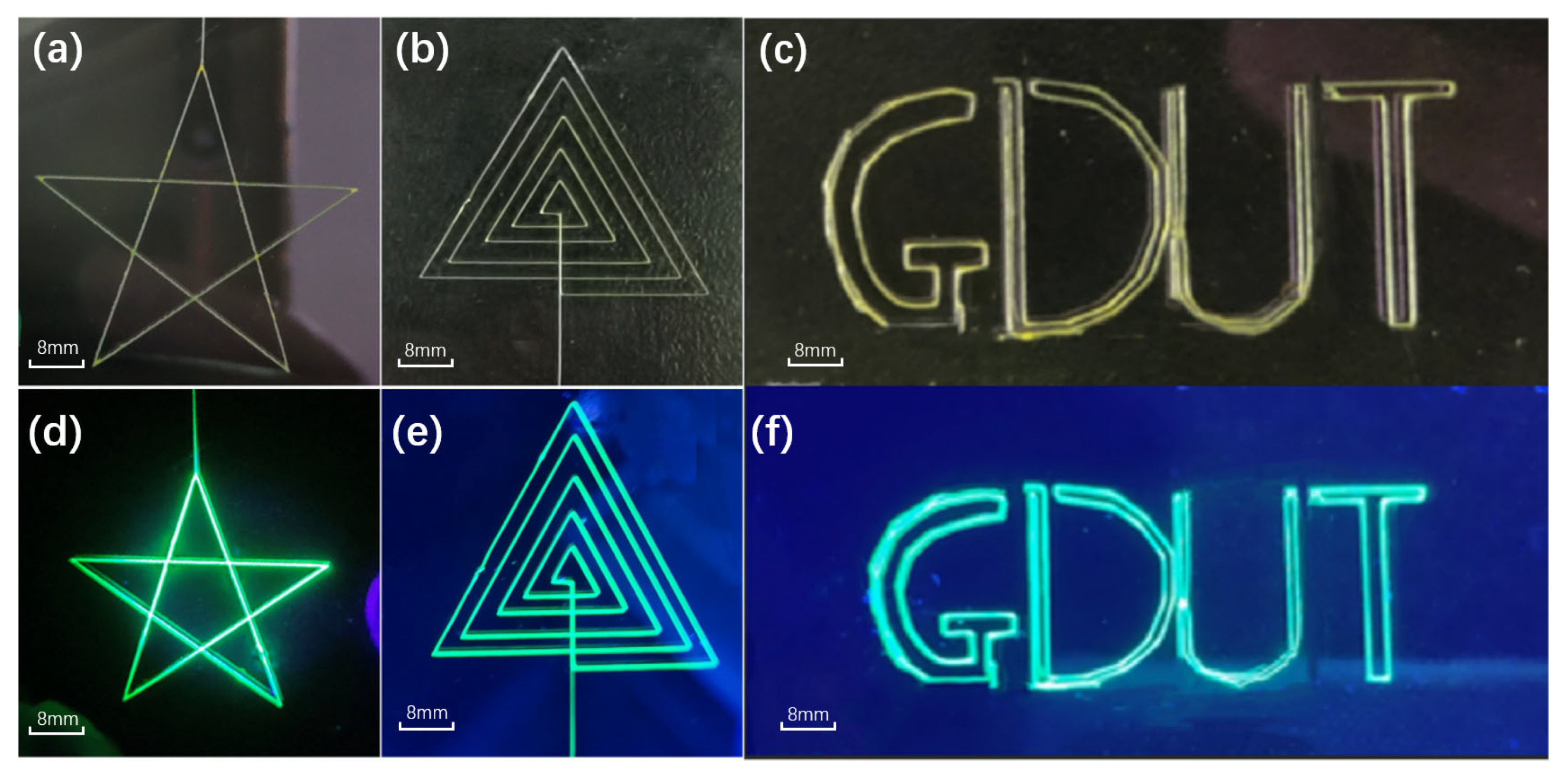
Figure 3.
(a–f) shows the process flow of composite fiber flexible packaging. (g) shows the flexible PDMS. (h,i) Fiber flexible display under ultraviolet light after transfer printing.
Figure 3.
(a–f) shows the process flow of composite fiber flexible packaging. (g) shows the flexible PDMS. (h,i) Fiber flexible display under ultraviolet light after transfer printing.
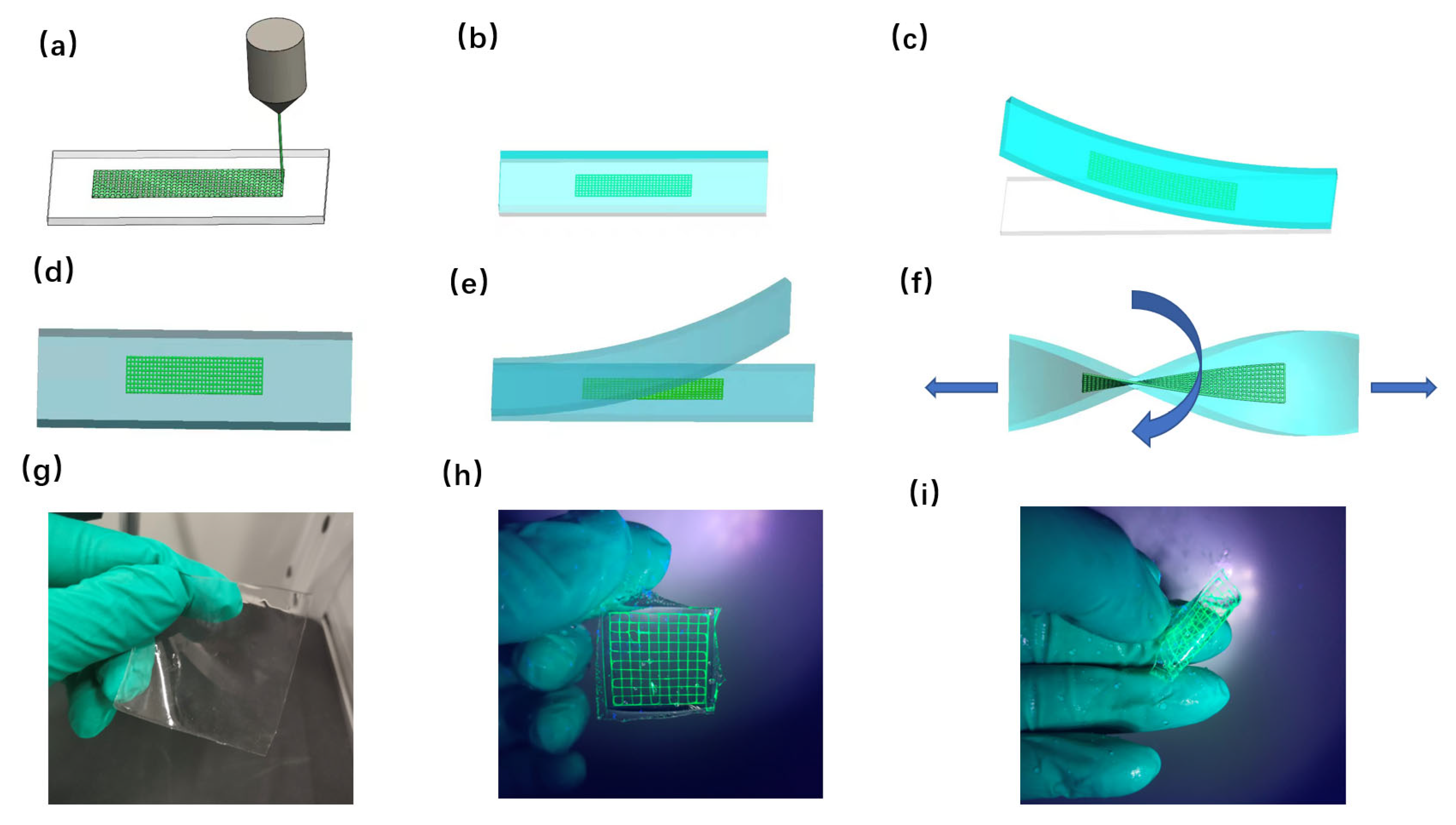
Figure 4.
XRD of PCL, CsPbBr3 and PCL@CsPbBr3.
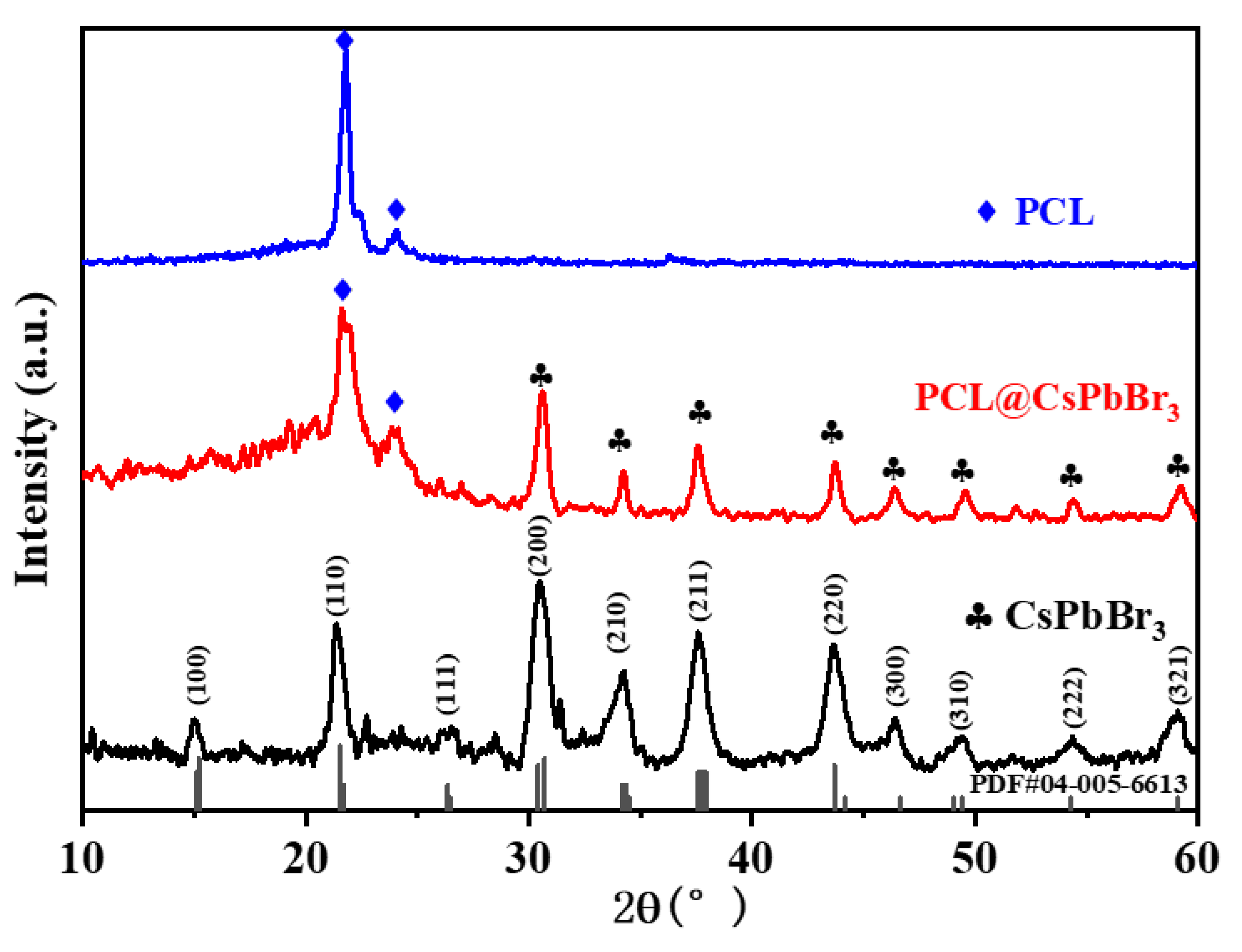
Figure 5.
(a,d,e) TEM and (c) HRTEM images of CSPbBr3, (b) Histogram of CsPbBr3 particle diameter (f–i) The EDX image and elemental mappings of Br, Cs and Pb elements in the CSPbBr3.
Figure 5.
(a,d,e) TEM and (c) HRTEM images of CSPbBr3, (b) Histogram of CsPbBr3 particle diameter (f–i) The EDX image and elemental mappings of Br, Cs and Pb elements in the CSPbBr3.

Figure 6.
(a) The PL of PCL, CsPbBr3 and PCL@CsPbBr3. (b) UV-Vis of PCL, CsPbBr3 and PCL@CsPbBr3. (c) Contact angle test of PCL@CsPbBr3. (d) Contact angle measurement data statistics (six times).
Figure 6.
(a) The PL of PCL, CsPbBr3 and PCL@CsPbBr3. (b) UV-Vis of PCL, CsPbBr3 and PCL@CsPbBr3. (c) Contact angle test of PCL@CsPbBr3. (d) Contact angle measurement data statistics (six times).
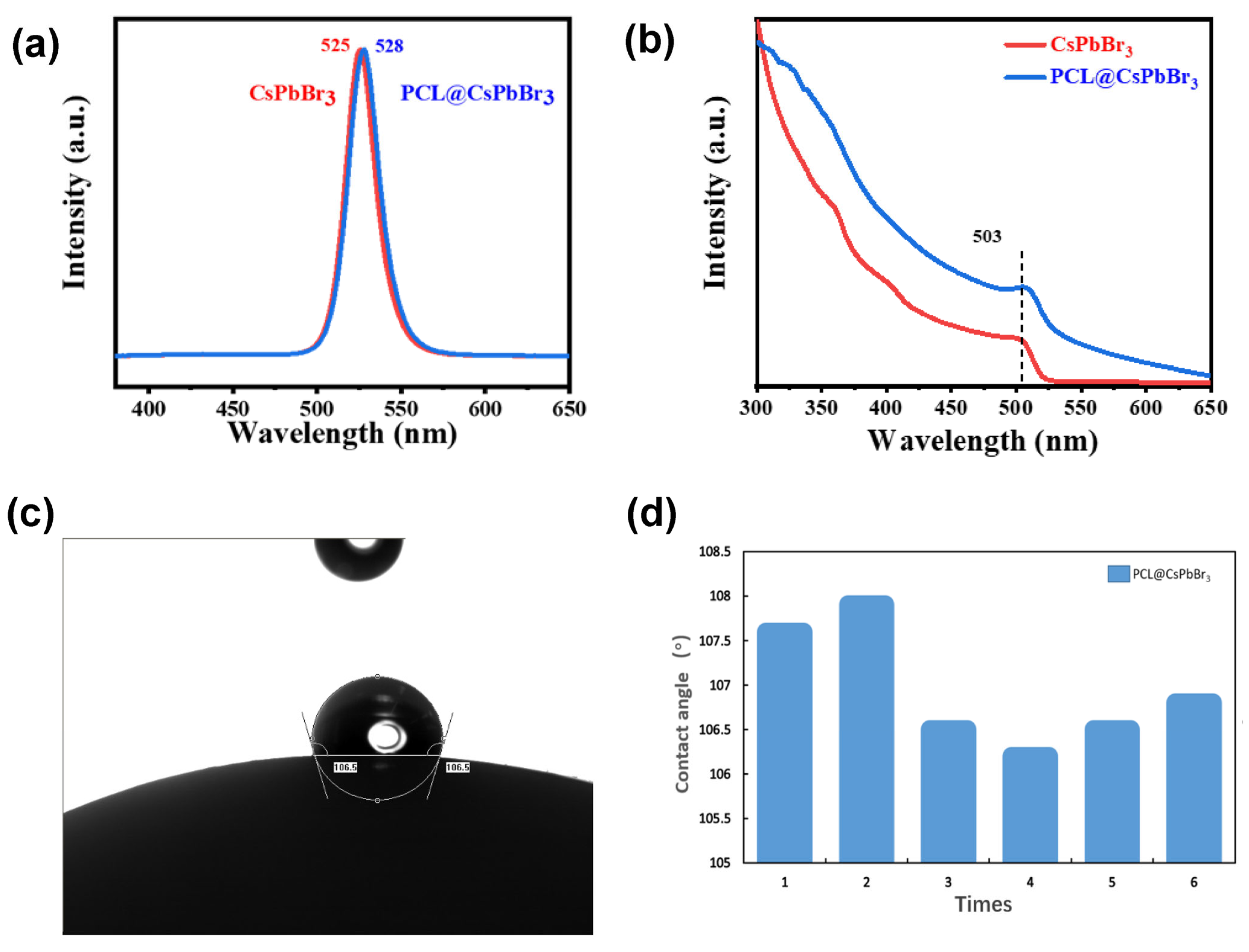
Figure 7.
CsPbBr3 QDs and PCL@CsPbBr3 water stability test. (a) CsPbBr3 QDs were put in water. (b) The PL of CsPbBr3 QDs put in water for 0 h, 1 h and 24 h. (c) PCL@CsPbBr3 were put in water. (d) The PL of PCL@CsPbBr3 put in water for 0 h, 12 h and 24 h.
Figure 7.
CsPbBr3 QDs and PCL@CsPbBr3 water stability test. (a) CsPbBr3 QDs were put in water. (b) The PL of CsPbBr3 QDs put in water for 0 h, 1 h and 24 h. (c) PCL@CsPbBr3 were put in water. (d) The PL of PCL@CsPbBr3 put in water for 0 h, 12 h and 24 h.
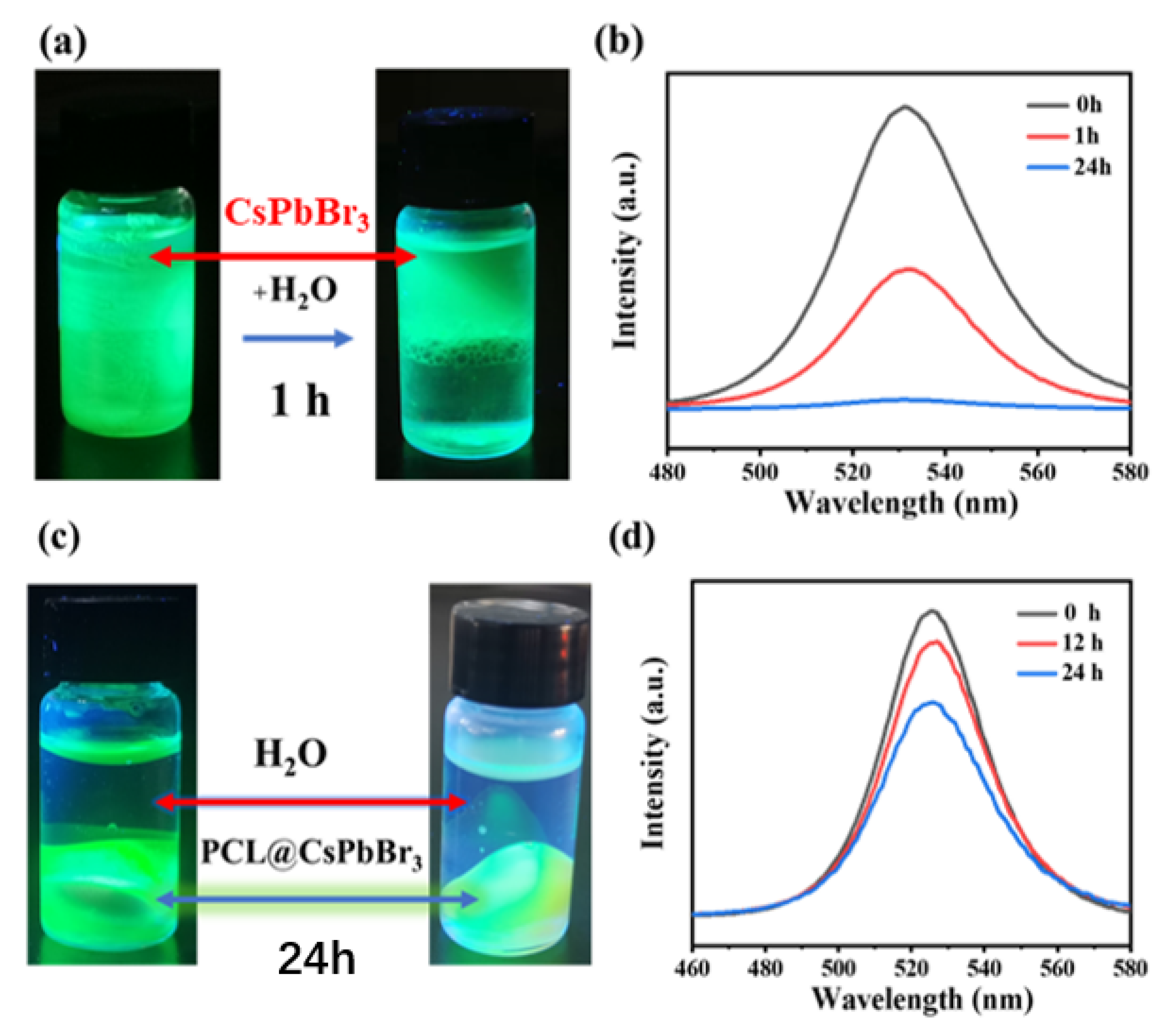
Figure 8.
(a,b,c) are SEM images of fibers at platform speeds of 5 mm/s, 10 mm/s and 15 mm/s. (d,e,f) are statistical diagrams of fiber diameter distribution at corresponding speeds.
Figure 8.
(a,b,c) are SEM images of fibers at platform speeds of 5 mm/s, 10 mm/s and 15 mm/s. (d,e,f) are statistical diagrams of fiber diameter distribution at corresponding speeds.
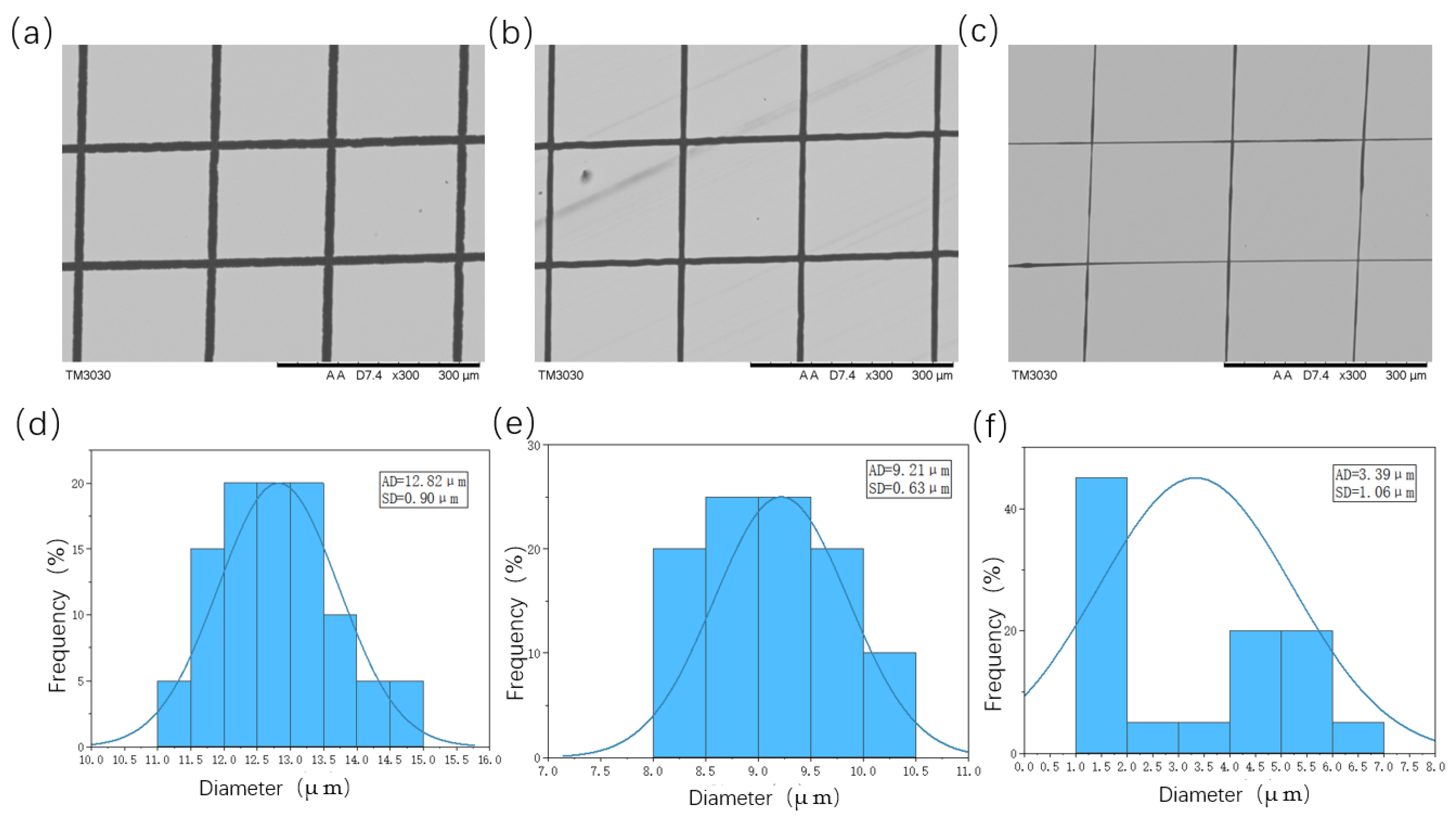
Figure 9.
PCL@CsPbBr3 stress—strain diagram of fiber (10 layers stacked).

Disclaimer/Publisher’s Note: The statements, opinions and data contained in all publications are solely those of the individual author(s) and contributor(s) and not of MDPI and/or the editor(s). MDPI and/or the editor(s) disclaim responsibility for any injury to people or property resulting from any ideas, methods, instructions or products referred to in the content. |
© 2023 by the authors. Licensee MDPI, Basel, Switzerland. This article is an open access article distributed under the terms and conditions of the Creative Commons Attribution (CC BY) license (https://creativecommons.org/licenses/by/4.0/).
Share and Cite
MDPI and ACS Style
Liu, M.; Lin, C.; Ou, W.; Wang, H.; Pan, C.; Ji, Y.; Zheng, H. Electrohydrodynamic Printing of PCL@CsPbBr3 Composite Fibers with High Luminescence for Flexible Displays. Coatings 2023, 13, 500. https://doi.org/10.3390/coatings13030500
AMA Style
Liu M, Lin C, Ou W, Wang H, Pan C, Ji Y, Zheng H. Electrohydrodynamic Printing of PCL@CsPbBr3 Composite Fibers with High Luminescence for Flexible Displays. Coatings. 2023; 13(3):500. https://doi.org/10.3390/coatings13030500
Chicago/Turabian StyleLiu, Maolin, Changqing Lin, Weicheng Ou, Han Wang, Chunyang Pan, Yuchen Ji, and Hehui Zheng. 2023. "Electrohydrodynamic Printing of PCL@CsPbBr3 Composite Fibers with High Luminescence for Flexible Displays" Coatings 13, no. 3: 500. https://doi.org/10.3390/coatings13030500
Note that from the first issue of 2016, this journal uses article numbers instead of page numbers. See further details here.