
Structural Optimized Design of a Powder Mixer for Multi-Material Directed Energy Deposition Based on CFD-DPM

Faculty of Materials Science and Engineering, Kunming University of Science and Technology, Kunming 650093, China
*
Author to whom correspondence should be addressed.
Coatings 2023, 13(4), 773; https://doi.org/10.3390/coatings13040773
Submission received: 8 March 2023
/
Revised: 2 April 2023
/
Accepted: 12 April 2023
/
Published: 15 April 2023
(This article belongs to the Special Issue High-Entropy Alloy Films, Coatings, and Bulks: Preparation, Manufacture, Properties, and Applications)
Abstract
:Directed energy deposition (DED) offers an unprecedentedly convenient and efficient additive manufacturing approach to novel alloy designs such as high entropy alloys. As a critical component of the novel DED system, a powder mixer to stably and uniformly mix different powders plays an important role in the DED process. In this paper, the computational fluid dynamics-discrete phase model (CFD-DPM) method was used to simulate the characteristics of the gas-solid coupled fluid inside the powder mixer. The influence of the structural details of the powder mixer on the motion characteristics of the gas-solid coupled fluid was investigated by numerical simulation. Based on the numerical simulation results, the range of parameters of critical structure such as the inlet angle, the diameter and height mixing chamber, and the height of the bottom was determined. The difference in powder mixing uniformity among different powder mixers was qualitatively analyzed through powder mixing experiments. The BSE-EDS results of mixed powder samples show that the mixer with reasonable structural parameters has better mixing uniformity. In summary, this work provides a powerful reference for the rapid optimization design of the powder mixer structure.
1. Introduction
At present, directed energy deposition (DED) has become an important method for developing experimental alloys [1,2,3]. The powder mixing methods of DED include asynchronous and synchronous mixing. Asynchronous mixing process has two steps, in which a variety of metal powders are mixed by ball milling firstly, and then the premixed powder is transported into the laser molten pool through the powder feeding system [4,5]. Synchronous mixing method can mix a variety of metal powders in real time, in the period of the powders transported from feeding hopper to the nozzle. Compared with the asynchronous mixing method, synchronous mixing process can save a lot of time for preparing the mixed powder, which is highly conducive to high-throughput development of advanced alloys [6].
The DED system is mainly composed of three subsystems, namely, energy source and focusing system (laser generator and laser light path), feeding system (powder feeder and powder mixer), and motion control system (CNC workbench and mechanical arm). To realize the synchronization of the powder mixing and powder feeding process, a novel DED technology [7,8,9] is proposed, which is mainly through adding a mixer for powder mixing in the powder feeding system.
J. del Val et al. [10] prepared functional gradient materials of 316L alloy and cobalt-based superalloys using a synchronous powder mixing oriented energy deposition system with a dynamic powder mixer. The dynamic mixer includes a large powder storage bin, a drive motor, rotating blades, a vibration mechanism, and a controller. However, these complex motion mechanisms have brought a series of new problems, such as the need to occupy a large installation space, increased maintenance costs, high energy consumption, and difficulty in cleaning after use. In response, relevant scholars have proposed a static powder mixer based on the principle of pneumatic vortex mixing. B. Xin et al. [11] designed a multi-stage tandem powder mixer, which is mainly composed of a cylindrical cavity and a built-in multi-stage spoiler. However, multi-stage spoilers may cause a significant loss of kinetic energy in the gas flow.
In summary, it is urgent to develop a mixer with a simple internal structure for the DED process that can stably and uniformly mix a variety of powders. Furthermore, it is also a crucial research topic to explore the structural design principles of the powder mixer. Consequently, this work will use a numerical simulation method combined with an experimental method to explore the reasonable structural details and determine the specific geometrical parameters of the powder mixer.
2. Materials and Methods
2.1. Synchronous Powder Mixing Principle
The powder mixer is one of the important components in the novel DED system, which is installed between the powder feeder and the deposition nozzle. Its working principle (see Figure 1) is that the metal powder is completely mixed in the mixer when the powder feeder uses inert gas to feed metal powder from multiple powder hoppers to the deposition nozzle.
In this paper, the powder mixing experiment was conducted using the powder feeding subsystem of the DED system, and the powder deposition process is not involved for the time being. The specific implementation method of the powder mixing experiment is to first send the three powders out of the rotary disk powder feeder at a rotational speed of 0.8 rad/min. The three powders are then transported through three pipelines to a powder mixer for mixing to obtain a mixed powder. Finally, the mixed powder is sprayed out via a nozzle. The samples of the mixed powder are collected at the confluence of the powder beam below the nozzle using the conductive adhesive. In the powder mixing experiment, the following three powders are used as raw materials: alloy Ni65, pure titanium powder, and niobium powder. The composition and particle size of the three powders are shown in Table 1.
2.2. Numerical Simulation
To study the influence of the structure of the powder mixer on the gas-solid two-phase flow field, a three-dimensional model of the original mixer is preliminarily established in this paper, and the main structural parameters are defined in Figure 2. The internal fluid domain of the powder mixer is used as the computational domain of the numerical simulation. The computational fluid dynamics-discrete phase model (CFD-DPM) [12] is used for the numerical simulation.
Large Eddy Simulation (LES) is used to simulate the motion of the gas phase in the mixing chamber. It directly calculates the Navier-Stokes (N-S) equation for the large eddy and simulates the small eddy by establishing subgrid-scale (SGS) models. After spatial filtering of continuity equation and momentum equation by filter function, the governing equation of fluid motion of Large Eddy Simulation is as follows:
where, , is filtered fluid velocity; , is spatial position of fluid; ρ is the continuous phase density; is time; is filtered pressure; is fluid viscosity.
The DPM method is used to simulate the movement of solid particle motion in the mixing cavity, and the motion equation of particles is as follows:
where mp is the particle mass, is the continuous phase velocity, is the particle velocity, ρ is the continuous phase density, ρp is the particle density, is the resistance, is the additional force, and τr is the relaxation time of the particle.
To make the simulation available and reasonable, three assumptions are proposed. (i) Gravity, buoyancy force, and drag force are considered, and other forces (Saffman’s lift force, virtual mass force, and pressure gradient force) are ignored because of the non-submicron powders utilized in this study. (ii) Only the elastic collision between particles and walls is considered, while the collision between particles is ignored since the mass flow of powder flow is lower than the standard dense phase flow. (iii) The powder is equal in size, and its spin is ignored.
Based on the working conditions, for the gas phase, the material property is set as argon, with the density ρ as 1.784 kg/m3 and the viscosity μ as 2.125 × 10⁻⁵ Pa·s. The inlet type is defined as Velocity-Inlet, and the initial inlet velocity u is defined as 2 m/s according to the gas flow (Q = 10 L/min). For the gas phase, the initial velocity of the particles at the inlet is defined as up and equals 2 m/s. The diameter of Ti, Nb, and Ni65 powders are defined as 28 μm, 36 μm and 43 μm, respectively, and their density is defined as 4850 kg/m3, 8430 kg/m3 and 8570 kg/m3, respectively. The simulation case used a workstation with Intel Xeon Platinum 8255C and 128G memory as the computing platform and used commercial CFD software for calculation.
3. Results and Discussion
3.1. The Angle of the Inlet and the Length of the Powder Conveying Pipe
We extracted the velocity contour (see Figure 3) of planes C1, C2, and C3 to investigate the influence of the inlet angle on the powder movement. By observing the three sampling planes of the 90° inlet feeder group, it can be clearly seen that the velocity distribution of the 2# and 3# feeders is uneven. Moreover, as the distance from the zero-point decreases, the gas stroke becomes longer, and this phenomenon of uneven velocity distribution gradually weakens. In addition, at each sampling plane, the low-speed zone is concentrated on the windward side, and the high-speed zone is concentrated on the leeward side. Furthermore, when Z = −16 mm, it can be observed that with the increase in the inlet angle, the distribution areas of the high-speed and low-speed areas of the velocity distribution of each sampling plane of the powder conveying pipe group and their velocity differences change. In the powder conveying pipe group with 90° inlet, the low-speed area of the 2# and 3# powder conveying pipes is on their respective windward sides, and the high-speed zone is on their respective leeward sides. However, in the 60° inlet feeder group, the difference in speed on the windward and leeward sides of the same pipe is not obvious, and the speed distribution of each pipe can be considered uniform. Surprisingly, the powder conveying pipe group with 30° inlet again shows an uneven velocity distribution, and the low velocity area is on the leeward side of each pipe, while the high velocity area is on the windward side of each pipe.
To further study this phenomenon and determine the structure and size of the pipe group, we set up four sampling lines and obtained the velocity distribution of the sampling lines as shown in Figure 4. It can be observed that the velocity curve, the leeward velocity curve, and the leeward velocity curve of the 2# and 3# powder conveying pipe show the same trend. As the inlet angle increases, the speed on the windward side gradually changes from less than the speed on the leeward side to greater than the speed on the leeward side in the second half of the curve. This also confirms the phenomenon in Figure 3 that as the inlet angle decreases, the low velocity area of each powder conveying pipe changes from the windward side to the leeward side, and the high velocity area changes from the leeward side to the windward side.
Compared with other pipe groups, the difference between the windward side velocity and the leeward side velocity of the 2# and 3# powder conveying pipes in the 60° inlet pipe group is the smallest in the second half of the curve, so the 60° inlet pipe group is the optimal structure. By measuring the Z-axis coordinates when the absolute value of the difference between the windward side velocity and the leeward side velocity is less than 0.25 for the first time, the length of each pipe can be determined as L1 ≥ 70 mm, L2 ≥ 55 mm, L3 ≥ 35 mm, respectively.
To intuitively express the influence of the pipe inlet angle on the powder movement, the particle distribution in mixer chamber when conveying powder with the 2# and 3# powder conveying pipes is extracted as shown in Figure 5. The powder distribution in the mixer with 90° and 30° inlet angle is observed, which further explains that the unreasonable inlet angle will lead to the uneven distribution of gas velocity in the powder conveying pipe and will then lead to the asymmetric distribution of powder after entering the powder mixing chamber. However, the powder distribution in the mixer with the 60° inlet angle is symmetrical, which indicates that it is reasonable to set the inlet angle at 60°.
3.2. The Mixing Chamber Size Range
The diameter and height of the mixer chamber have an important influence on whether the confined jet can form the desired spatial gas flow characteristics. Therefore, to explore a reasonable range of diameter and height for the mixer chamber, the velocity contours and streamline diagrams of the plane-A were extracted from the powder mixers with different diameters and heights, as shown in Figure 6. When Dm = 3De (where Dm is the diameter and of the mixer chamber, De is the equivalent diameter of the jet), as the chamber height increases, the reflux phenomenon at the top of the chamber becomes more and more obvious, and the reflux area gradually increases. However, the divergence at the initial segment of jet does not diminish. This divergence causes a part of the outer gas flow to leave the chamber directly from the outlet without following the flow direction of the main jet. This is because when the maximum diameter Dm of the chamber is small, the layout range reserved for the outlet is smaller, and the distance between the outlet axis and the inlet axis is smaller. At this point, the low-pressure region formed by the high-speed gas flow near the outlet will, under the influence of the Bernoulli effect, strongly influence the direction of the outward gas flow in the initial jet segment, so that the restricted jet cannot fully develop. This would be detrimental to our purpose of mixing with the gas flow.
When H = 3De (where H is the height of the mixing chamber), as the diameter of the mixing chamber increases, not only the reflux phenomenon at the top of the chamber becomes more obvious, but also the reflux area gradually increases. In addition, the divergence phenomenon of the initial segment of the jet is significantly weakened, the jet is more concentrated, and more external gas flows are transported to the top of the chamber with the jet main body, and the swirling motion is carried out under the restriction of the space boundary, forming a larger reflux vortex zone. In summary, it can be assumed that the approximate range of chamber sizes that satisfy the requirements is Dm ≥ 4De, H ≥ 3De.
3.3. The Bottom Height
Although a reasonable chamber diameter and height are conducive to the formation of the desired space confined jet structure, the divergence phenomenon of the initial segment of the confined jet has not completely disappeared. Therefore, this paper further discusses the influence of Hb (the bottom height) on the divergence phenomenon of the initial segment of the confined jet. The velocity contours and the corresponding particle distribution diagram of the powder mixers with different bottom heights are extracted. In Figure 7a–c, there is still a divergence phenomenon in the initial segment of the jet, where part of the gas flow outside the initial segment of the jet separates from the main body of the jet and moves directly towards the outlet. Then Figure 7d shows that this phenomenon disappears, and a complete reflux area is formed in the chamber, which makes the outer gas flow of the initial jet segment not to escape to the outlet, and these gas flows will participate in the subsequent flow process. This shows that as Hb (the bottom height) increases, the effect of the low-pressure area at the outlet on the airflow outside the initial segment of the jet is reduced. Further observation of the corresponding particle distribution as shown in Figure 7e–h also shows that as Hb increases, the amount of powder that escapes directly without mixing decreases. When Hb ≥ 1.5De, the divergence phenomenon of the initial segment of jet disappears, forming a standard restricted jet structure in the chamber, and the powders will no longer escape without mixing.
3.4. Experimental Results of Powder Mixing Uniformity
In conclusion, the structure of the powder mixer is optimized by the numerical simulation method. However, experimental results are needed to demonstrate whether our optimization of the mixer structure can improve the mixing uniformity of the powder. We use the DED system equipped with four powder mixers with different bottom heights for powder mixing tests. Based on the quality of three powders, the following powder conveying methods are adopted: nickel powder is conveyed by the 1# powder conveying pipe, niobium powder is conveyed by the 2# powder conveying pipe, and titanium powder is conveyed by the 3# powder conveying pipe.
Finally, four powder samples were collected using conductive adhesive and analyzed using scanning electron microscope-energy dispersive spectrometer (SEM-EDS) method. The analysis results are shown in Figure 8. According to the observation in Figure 8a,b, the titanium powder in the sample forms a wide range of dense distribution, which is because a large amount of titanium powder escapes directly from the outlet without mixing. The escape phenomenon is shown in Figure 7a,b. Therefore, as is shown in Figure 8a,b, at the initial stage of the operation of the powder feeding system, the mixed powder with titanium powder as the main component is obtained. However, in Figure 8c,d, with the increase in the height of the bottom of the mixer, the escaping powder is greatly reduced, the phenomenon of dense distribution of titanium powder is improved, and the distribution of various powders tends to be uniform. The above results indicate that increasing the height of the bottom can indeed improve the mixing uniformity of the powder.
4. Conclusions
In this study, the influence of the structure on the gas-solid two-phase flow has been numerically investigated for powder mixers. The main results can be summarized as follows:
The inlet angle significantly affects the velocity distribution in the powder conveying pipe and then the powder distribution in the chamber. When the inlet angle is 60°, the powder shows a symmetrical distribution after hitting the top wall of the mixer chamber. Therefore, the reasonable pipe group size range is determined as α = 60°, L1 ≥ 70 mm, L2 ≥ 55 mm, and L3 ≥ 35 mm.
The size range of the mixing chamber has a significant influence on whether the confined jet can form the desired spatial gas flow characteristics. Increasing the diameter and height of the chamber will assist in the full development of the confined jet. It can be assumed that the approximate range of chamber sizes that will satisfy the requirements is Dm ≥ 4De, H ≥ 3De.
Increasing the height of the bottom can effectively avoid the Bernoulli effect caused by the low-pressure zone near the outlet on the initial segment of the jet and then improve the existing divergence phenomenon, which is conducive to the mixing the powder in the subsequent flow process. According to the simulation results, the range of bottom height is determined as Hb ≥ 1.5De.
We use the DED system equipped with four powder mixers with different bottom heights to test the powder mixing. According to the EDS analysis results of the samples, the powder distribution is affected by the mixer structure. Moreover, a reasonable structure helps to improve the mixing effect.
Author Contributions
X.Z. conceived the idea. X.Z. and G.G. designed the model of mixer. G.G. performed the numerical simulation. X.Z., G.G., Y.H., J.A., Y.C. and J.W. carried out characterization and mixing experiments. G.G., X.Z. and M.X. fabricated the mixers. G.G. and X.Z. analyzed the data, drafted the manuscript, discussed, and edited the manuscript. J.A., Y.C. and J.W. X.Z. reconfirmed the microstructure of mixed powder. X.Z. supervised the work. All authors contributed to the discussion of the results and commented on the manuscript. All authors have read and agreed to the published version of the manuscript.
Funding
This research was funded by Xiaowei Zhang’s Xingdian Talents Project, grant number YNWR-QNBJ-2020-007.
Institutional Review Board Statement
Not applicable.
Informed Consent Statement
Not applicable.
Data Availability Statement
The data that support the findings of this study are available on request from the corresponding author, [Zhang, X.], upon reasonable request.
Conflicts of Interest
The authors declare that they have no known competing financial interests or personal relationships that could have appeared to influence the work reported in this paper.
References
- Vecchio, K.S.; Dippo, O.F.; Kaufmann, K.R.; Liu, X. High-throughput rapid experimental alloy development (HT-READ). Acta Mater. 2021, 221, 117352. [Google Scholar] [CrossRef]
- Islam, Z.; Nelaturu, P.; Thoma, D.J. A dimensionless number for high-throughput design of multi-principal element alloys in directed energy deposition. Appl. Phys. Lett. 2021, 119, 231901. [Google Scholar] [CrossRef]
- Kim, C.K.; Jeong, J.I.; Choi, S.G.; Kim, J.H.; Cho, Y.T. High-throughput directed energy deposition process with an optimized scanning nozzle. J. Mater. Process. Technol. 2021, 295, 117165. [Google Scholar] [CrossRef]
- Pan, Q.; Kapoor, M.; Mileski, S.; Carsley, J.; Lou, X. Technical basis of using laser direct energy deposition as a high-throughput combinatorial method for DC-cast Al-Mn alloy development. Mater. Des. 2021, 212, 110290. [Google Scholar] [CrossRef]
- Li, W.; Zhang, J.; Zhang, X.; Liou, F. Effect of optimizing particle size on directed energy deposition of Functionally Graded Material with blown Pre-Mixed Multi-Powder. Manuf. Lett. 2017, 13, 39–43. [Google Scholar] [CrossRef]
- Zhang, X.; Yin, J.; Lei, Q.; Meng, X.; Chen, X.; Li, Z. High-throughput directed energy deposition-based manufacturing combined with machine learning to fabricate gradient-composition Cu-Fe-Cr alloys. Mater. Lett. 2022, 308, 131247. [Google Scholar] [CrossRef]
- Kelly, J.P.; Elmer, J.W.; Ryerson, F.J.; Lee, J.R.I.; Haslam, J.J. Directed energy deposition additive manufacturing of functionally graded Al-W composites. Addit. Manuf. 2021, 39, 101845. [Google Scholar] [CrossRef]
- Chen, J.; Xie, S.; He, H. A novel method of utilizing static mixer to obtain mixing homogeneity of multi-species powders in laser metal deposition. Chin. J. Aeronaut. 2023, 36, 423–433. [Google Scholar] [CrossRef]
- Han, Y.; Zhang, X.; Liu, H.; Xu, M.; Gao, G. Structural design, numerical examination and experimental approach of the multi-powder mixer for directed energy deposition. Powder Technol. 2022, 398, 117144. [Google Scholar] [CrossRef]
- del Val, J.; Arias-González, F.; Barro, O.; Riveiro, A.; Comesaña, R.; Penide, J.; Lusquiños, F.; Bountinguiza, M.; Quintero, F.; Pou, J. Functionally graded 3D structures produced by laser cladding. Procedia Manuf. 2017, 13, 169–176. [Google Scholar] [CrossRef]
- Xin, B.; Cheng, G.; Yao, J.; Gong, Y. Powder Mixing Mechanism of Laser Cladding Forming for Adaptive FGM. J. Northeast. Univ. (Nat. Sci.) 2020, 41, 1123. [Google Scholar] [CrossRef]
- Koyunoğlu, C.; Gündüz, F.; Karaca, H.; Çınar, T.; Soyhan, G.G. Developing an adaptive catalyst for an FCC reactor using a CFD RSM, CFD DPM, and CFD DDPM-EM approach. Fuel 2023, 334, 126550. [Google Scholar] [CrossRef]
Figure 1.
The novel DED principle and the experimental method.

Figure 2.
(a–c) Geometric modeling of powder mixer; (d) Dimensioning diagram; (e–g) The data sampling position.
Figure 2.
(a–c) Geometric modeling of powder mixer; (d) Dimensioning diagram; (e–g) The data sampling position.

Figure 3.
Velocity contour on the sampling plane of the powder conveying pipe group.

Figure 4.
Velocity curves on the sampling line of the powder conveying pipe group.
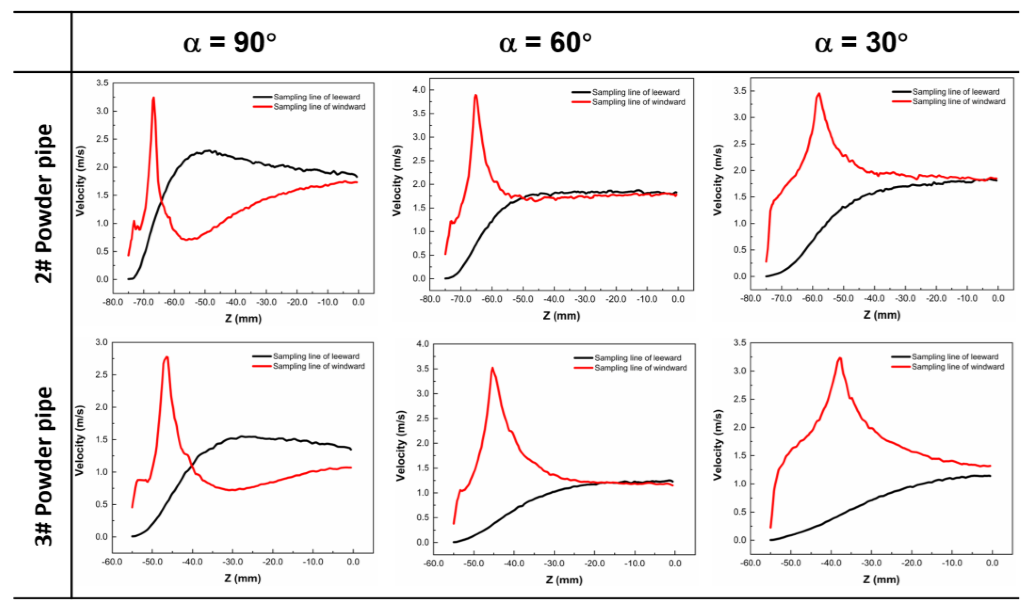
Figure 5.
Particle distribution of the 2# and 3# powder conveying pipe.
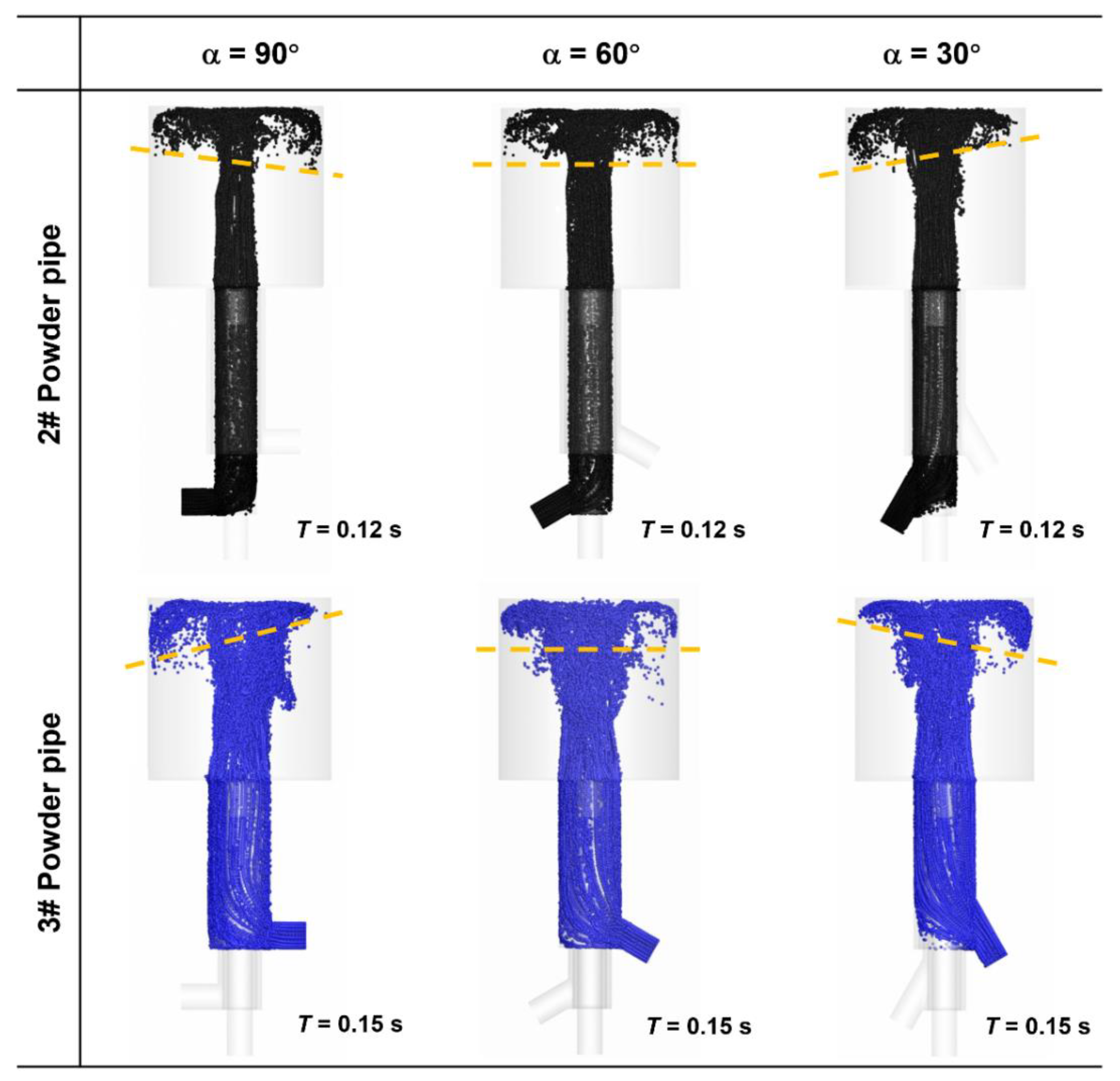
Figure 6.
Velocity contours and streamlines of different chamber sizes.

Figure 7.
(a–d) Velocity contour and streamline; (e–h) Particle distribution diagrams of mixers with different bottom heights.
Figure 7.
(a–d) Velocity contour and streamline; (e–h) Particle distribution diagrams of mixers with different bottom heights.
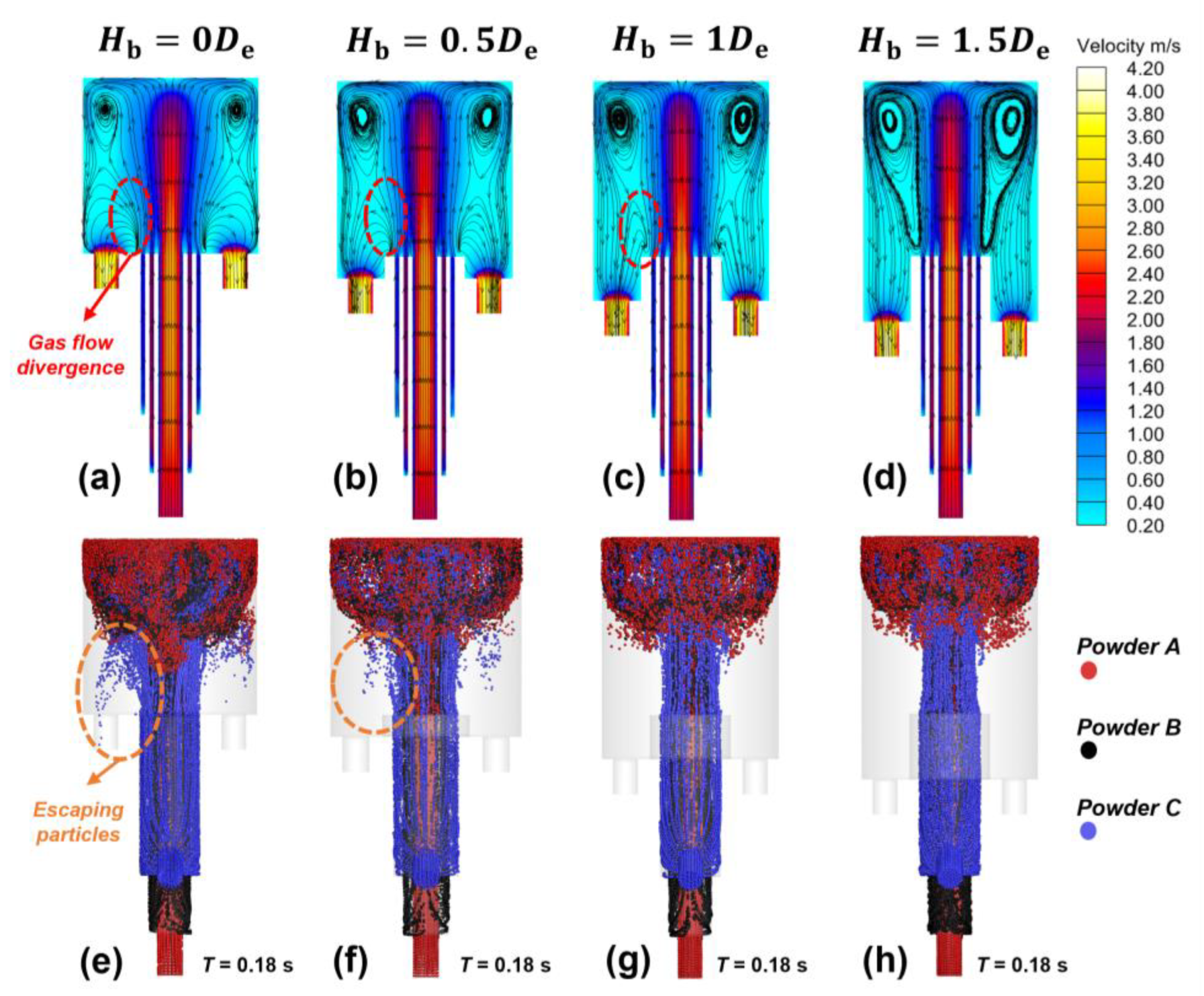
Figure 8.
Morphology and element distribution of the mixed powder.


Table 1.
Powder composition and particle size.
| Powder | Composition (wt.%) | Size Range (μm) | D50 (μm) | ||||||||
|---|---|---|---|---|---|---|---|---|---|---|---|
| C | N | O | Si | Ti | Nb | Ni | Fe | Cr | |||
| Ti | 0.009 | 0.025 | 0.012 | 0 | bal | 0 | 0 | 0.032 | 0 | 15–53 | 28 |
| Nb | 0.009 | 0.009 | 0.073 | 0.002 | 0.002 | bal | 0.003 | 0.008 | 0.003 | 15–45 | 36 |
| Ni65 | 1.100 | 0 | 0.080 | 4.260 | 0 | 0 | bal | 14.620 | 18.620 | 25–100 | 43 |
Disclaimer/Publisher’s Note: The statements, opinions and data contained in all publications are solely those of the individual author(s) and contributor(s) and not of MDPI and/or the editor(s). MDPI and/or the editor(s) disclaim responsibility for any injury to people or property resulting from any ideas, methods, instructions or products referred to in the content. |
© 2023 by the authors. Licensee MDPI, Basel, Switzerland. This article is an open access article distributed under the terms and conditions of the Creative Commons Attribution (CC BY) license (https://creativecommons.org/licenses/by/4.0/).
Share and Cite
MDPI and ACS Style
Gao, G.; Zhang, X.; Xu, M.; Han, Y.; Ao, J.; Cai, Y.; Wang, J. Structural Optimized Design of a Powder Mixer for Multi-Material Directed Energy Deposition Based on CFD-DPM. Coatings 2023, 13, 773. https://doi.org/10.3390/coatings13040773
AMA Style
Gao G, Zhang X, Xu M, Han Y, Ao J, Cai Y, Wang J. Structural Optimized Design of a Powder Mixer for Multi-Material Directed Energy Deposition Based on CFD-DPM. Coatings. 2023; 13(4):773. https://doi.org/10.3390/coatings13040773
Chicago/Turabian StyleGao, Guochao, Xiaowei Zhang, Meng Xu, Yibo Han, Jingxuan Ao, Yaozeng Cai, and Jinzhe Wang. 2023. "Structural Optimized Design of a Powder Mixer for Multi-Material Directed Energy Deposition Based on CFD-DPM" Coatings 13, no. 4: 773. https://doi.org/10.3390/coatings13040773
Note that from the first issue of 2016, this journal uses article numbers instead of page numbers. See further details here.