Article

Sol–Gel Silica Coatings for Corrosion Protection of Aluminum Parts Manufactured by Selective Laser Melting (SLM) Technology

1
Mechanical and Aerospace Engineering Department, Sapienza University of Rome, Via Eudossiana 18, 00184 Roma, Italy
2
Centro Ricerche Fiat Scpa, Strada Torino 50, 10043 Orbassano, Italy
3
Nalucoat Benefit Srl, Via Canale 300, 42013 Casalgrande, Italy
4
Nanoprom Chemicals Srl, Via Canale 300, 42013 Casalgrande, Italy
*
Author to whom correspondence should be addressed.
Coatings 2023, 13(6), 1081; https://doi.org/10.3390/coatings13061081
Submission received: 13 March 2023 / Revised: 6 June 2023 / Accepted: 7 June 2023 / Published: 11 June 2023

Abstract

:
Metal additive manufacturing is a rapidly growing field based on the fabrication of complex parts with improved performance. The advantages of using this technology include the production of shapes that cannot be produced by traditional machining technologies, the possibility of using trabecular reinforcing structures, and the ability to make parts with topological optimization that allow for increased performance and decreased mass of the parts produced. Metal parts produced by selective laser melting technology exhibit high surface roughness, which limits their direct implementation. Corrosion protection of these surfaces is difficult, especially for galvanic processes. This paper analyzes the possibility of using sol–gel silica (silicon oxide) coatings to effectively protect various surfaces of aluminum alloys produced by selective laser melting technology. Silicon oxide sol–gel protective coatings have demonstrated excellent chemical stability and corrosion resistance, being able to be applied in very thin layers. These properties make them excellent candidates for protecting additive-manufactured metal parts, especially as-built surfaces with a high surface roughness. Nanostructured silica sol–gel protective coatings have demonstrated excellent corrosion resistance and have the potential to replace the highly toxic chromium-based galvanic treatments. Using nanostructured silica sol–gel coatings, aluminum parts can be seamlessly integrated into circular-economy cycles.

1. Introduction

In recent decades, industry has made great strides in the production of consumer goods, thanks in part to the availability of cheap energy from fossil fuels and the development of industrial control systems based on increasingly sophisticated and effective computer systems (e.g., vision systems, robotic systems, etc.) [1].
The steady improvement in economic and social conditions has also pushed markets toward an assumption of continued growth, which is also corroborated by the expansion of new customers resulting from the globalization of markets [2].
Unfortunately, the industry’s strong expansionary drive has led to the indiscriminate use of natural resources without regarding the global impacts; this aspect, combined with the extensive use of fossil fuels, causes sudden and significant changes in the ecosystem, especially at the atmospheric level [3,4]. Moreover, pollution of water and soil by microplastics is an incontrovertible phenomenon, which is constantly and worryingly increasing [5,6].
Additive manufacturing (AM), also known as 3D printing, uses a Computer-Aided Design (CAD) model to define objects in 3D and then fabricate them layer by layer [7].
It was initially used for prototyping parts, but technological evolution has transformed this field [8,9], making it a mainstream manufacturing sector. One of the main advantages of AM is that the entire process chain can be completely digital. The product is designed with CAD software and the processed files can be sent via the Internet to a 3D printer to print the object anywhere in the world. As a result, logistical and warehousing impacts are reduced, and stored parts can be drastically minimized and printed as needed [10].
Unlike traditional industrial manufacturing, AM enables the efficient use of resources [11], reducing energy costs and special waste typically produced by traditional technologies such as casting, machining, and plastic deformation.
Through the production of AM-made metal parts, used resources and wastes are minimized, and when a product reaches the end of its life cycle, it is modified so that it can be reused, creating new value [12].
AM is therefore also seen as a powerful enabler of the circular economy, enabling the reduction of energy consumption to reduce operating costs and greenhouse gas emissions. In fact, producing aluminum from recycled sources requires 95 percent less energy than production from mined ore [13].
Aluminum’s characteristic properties make it an ideal material for the purposes of the new market drivers embodied in the concepts of circular economy and environmental sustainability [14].
Its high strength-to-stiffness-to-weight ratios, good formability, good corrosion resistance, and recycling potential make it an ideal candidate to replace heavier materials, e.g., steel, in industry. The extensive use of aluminum alloys helps to reduce the weight of fabricated components by enabling improved point-of-view efficiency and resulting in lower energy consumption and, thus, less air pollution [15].
Aluminum alloy parts made by traditional manufacturing methods (casting, forging, and extrusion) have several process-related issues which generally contribute to a medium-to-large microstructure. Conversely, parts produced by SLM technology have a very fine microstructure [16], which allows for improved mechanical performance [17]. A lower fatigue strength remains a drawback, which can be solved by using high-pressure heat treatments [18].
SLM technology is used to produce high-value parts with very complex designs, which cannot be made with conventional technologies; the high cost of this process prevents its extensive use in industry, but combined parts made in AM with parts made with conventional technologies at low production costs make its use in industrial production possible, making hybrids that use AM technology only where it is really needed [19].
The aluminum parts’ corrosion resistance is typically increased by a protection technology which must not contrast principles of sustainability and material reuse of the circular economy. Historically, aluminum parts were protected by chromate conversion coating. It primarily serves as a corrosion inhibitor which is made by conversion and used to passivate alloys of stainless steel, aluminum, zinc, and other metals [20]. Chromate conversion coatings are usually applied by soaking the part in a chemical bath of acidic solution of chromate and fluoride until a film of the desired thickness is formed, removing the part, rinsing it, and allowing it to dry. The process is usually performed at room temperature, with a few minutes of soaking. Bath composition varies widely depending on the material to be coated and the desired effect. The main components of the solutions used for forming chromate-conversion-coating films are trivalent and hexavalent chromium [21]; the base metal; various oxides; water; and several additional components, such as phosphates, sulfates, and fluorides. These elements are highly toxic, the hexavalent chromium is carcinogenic, and trivalent chromium tends to migrate to the hexavalent formulation [22]; hence, the parts coated by this process are classified as special waste at the end of their operating life and cannot be disposed of in ordinary waste cycles (landfill or recycling).
With a view to environmental sustainability and the circular economy, it is necessary to find other coatings for the corrosion protection of metals and, in particular, aluminum alloys, which are the perfect candidate for the circular economy because, at the end of its life, an aluminum-alloy component can be re-melted to become raw material for processing or, in the case of AM technology, can be atomized into powders for use with SLM technology [23].
In the late 1990s, silanes encountered great interest sparked by the possibility of using these compounds as “coupling agents” between metals and their coatings, as well as between metals and conventional painting. Moreover, these primers can be used by themselves or nano-additivated in various ways, as corrosion inhibitors [24,25].
Sol–gel coatings can be deposited to the metal substrate through various techniques, such as dip-coating, spin-coating, and spraying, which do not need a high temperature and vacuum conditions. In recent years, sol–gel coatings have been studied extensively for the replacement of the toxic and carcinogenic chromate-containing coatings [26,27].
One methodology for the formation of thin and strong sol–gel films at room temperature is based on the use of sol–gel nanoparticles that are pre-formed in a solution. These pre-assembled nanoparticles (SNAP: Self-Assembled Nanoscale Particle) polymerize without forming the porosities associated with hydrolysis and condensation products [28].
This technology enables the fabrication of silicon-based sol–gel coatings whose coating formation properties, barrier properties, performance, and morphology are formulated to provide thin, dense films using only the room-temperature process based on standard organic crosslinking reactions to form the film after application [29].
A set of corrosion tests were conducted on aluminum alloy specimens made with SLM technology in order to validate the protection effectiveness of a commercial coating made in silica sol–gel technology. The expected results aim to confirm that this corrosion-protection system is effective and can replace chromic-conversion treatments to make aluminum parts eco-friendly and enable them for use in the circular-economy supply chain.

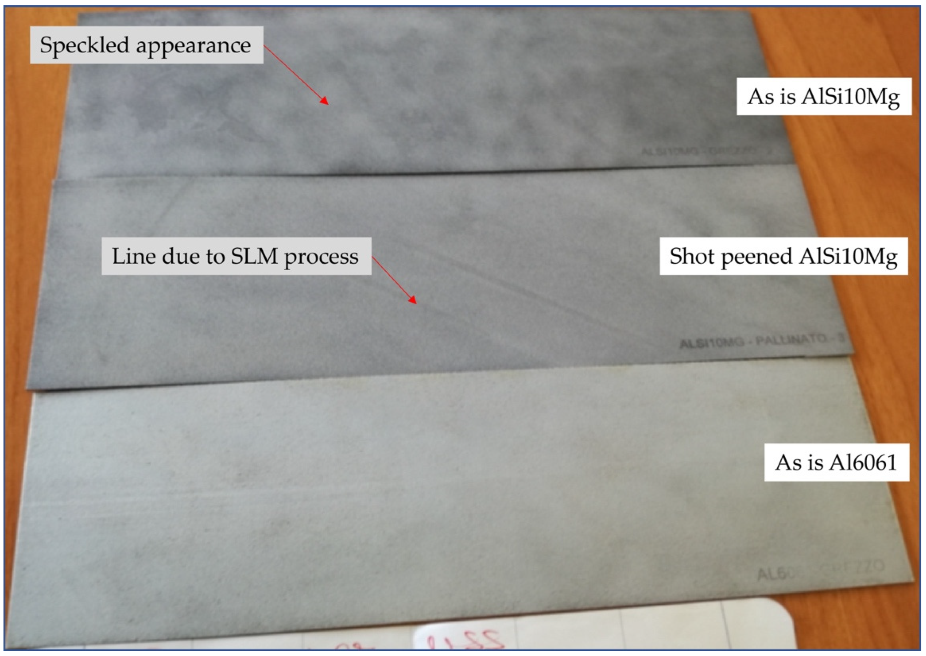
2. Materials and Methods

The AlSi10Mg and Al6061 alloy specimens tested in this work were fabricated by using SLM technology. The specimens are sheets of various sizes: 250 × 75 × 1 mm3, 50 × 50 × 2 mm3, 150 × 75 × 2 mm3, and 80 × 80 × 2 mm3.
The used machine is an EOS M280 (EOS GmbH, Krailling, Germany) equipped with a 400 W ytterbium fiber continuum laser (wavelength 1060–1100 nm) that is characterized by a beam spot diameter of 100 µm and a building volume of 250 × 250 × 325 mm3.
For AlSi10Mg specimens, a commercial EOS Aluminum AlSi10Mg powder was used; for Al6061 specimens, a commercial A6061-RAM2 (Elementum 3D, Erie, CO, USA) powder was used. The employed process parameters for the two alloys are reported in Table 1.
A commercial silica sol–gel coating, commercially called Polysil® SC, produced by Nanoprom Chemicals, was used to test the corrosion-protection performance of the SLM specimens.
The coating was applied by spray in a spray booth without any specific special precautions. Polysil® crosslinks at room temperature due to moisture in the air; after about 60 min, the coating is dry to the touch; however, at least 72 h is required to achieve complete crosslinking, or it can be cured at 80° in an oven for 2 h, as recommended by Nanoprom.
The main test is the 168-hour salt-spray test according to ASTM B117 [30]/UNI EN ISO 9227 [31]. The geometric dimensions of the used specimen are 250 × 75 × 1 mm3. In addition to the salt-spray test, further tests were carried out to verify corrosion resistance and to evaluate static and dynamic adhesion (thermal cycling) on a partly as-built surface and partially milled specimens.
Specifically, the additional tests that were carried out are as follows:
  • Adhesion, according to ASTM d3359-17
Adhesion refers to the ability of a coating or paint to stick to a substrate or surface. ASTM D3359-17 [32] is a standard test method for measuring the adhesion of coatings to substrates. It is commonly used in the paint and coating industry to evaluate the quality and durability of coatings on a variety of substrates. The ASTM D3359-17 test method involves applying a grid pattern on the coating’s surface with a cutting tool and then applying an adhesive tape over the grid pattern. The tape is then removed quickly, at a 90-degree angle to the surface, and the amount of coating that remains on the surface is evaluated based on the grid pattern. The specimen dimensions are 50 × 50 × 2 mm3.
  • Thickness analysis, according to UNI EN ISO 2808:2019
This test was performed according to UNI EN ISO 2808:2019, with method 6A, based on the principle of magnetic induction. The Elcometer 456 F/NF probe was used for coating-thickness measurement; this is a digital coating-thickness gauge that is capable of measuring the thickness of magnetic (ferrous) and nonmagnetic (nonferrous) coatings on a variety of substrates. The specimen size is 140 × 100 × 2 mm3.
  • Neutral salt-spray test, according to MIL-STD-810G w/change 1 Method 509.6
The neutral salt-spray test is a test method used to evaluate the corrosion resistance of materials and coatings. MIL-STD-810G w/change 1 Method 509.6 is the standard that was used and specifies the procedures for conducting the neutral salt-spray test.
The test involves exposing the test specimen, which can be a material or a coated surface, to a salt-spray mist in a controlled environment for a set period of time. The salt-spray mist was composed of a 5% sodium chloride solution. The test was performed in an Angelantoni ACS Mod. DCTC 600P chamber for neutral salt-spray testing, using the following parameters:
(a)
24 h of salt spray (T 35 °C, pH 7.0);
(b)
24 h under drying conditions at 23 °C +/−5 °C and humidity of 50%UR +/−10%UR;
(c)
24 h salt spray (T 35 °C, pH 7.0);
(d)
24 h under drying conditions at 23 °C +/−5 °C and humidity of 50%UR +/−10%UR.
During the test, the specimen is inspected periodically to assess the extent of corrosion or damage to the surface. The size of the specimen is 150 × 75 × 2 mm3.
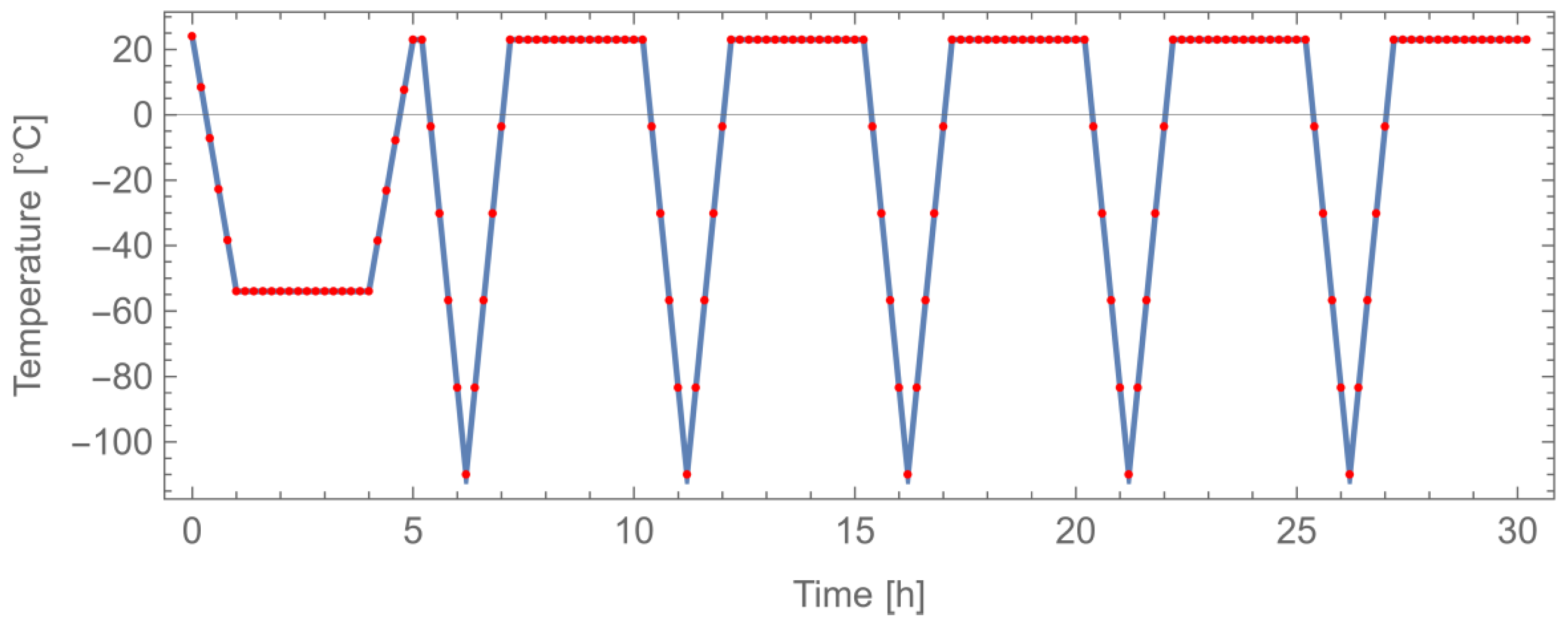
  • Determination of thermal-cycling resistance
The determination of thermal-cycling resistance is a test method used to evaluate the ability of a material or product to withstand changes in temperature over time. This test method is important in determining the durability and reliability of a coating that will be exposed to temperature changes during its lifetime.
The reference application is aerospace; therefore, the reference cycles simulate flight conditions for aircraft. The following thermal conditioning was performed:
Repetition of 5 times for the first cycle:
  • Ramp of 1 h down to the temperature of −54 °C;
  • Maintain the temperature of −54 °C for 3 h;
  • Ramp of 1 h up to the temperature of 23 °C;
  • Maintain the temperature of 23 °C for 10 min.
Repetition of 5 times for the second cycle:
  • Ramp of 1 h down to the temperature of −110 °C;
  • Maintain the temperature of −110 °C for 3 min;
  • Ramp of 1 h up to the temperature of 23 °C;
  • Maintain the temperature of 23 °C for 3 h.
During the test, the test specimen is monitored for any changes or damage that may occur as a result of the temperature changes. This can include cracking, delamination, or other forms of physical or chemical degradation. The specimen size is 140 × 100 × 2 mm3.
The tests were performed on as-is AlSi10Mg and Al6061 SLM specimens. For the additional tests, after the fabrication, specific AlSi10Mg specimens were processed by shot-peening and milling. The former was provided using a Lampugnani shot-peening LC/S machine loaded by glass-sphere particles at 5 bar pressure for 30 s. The milling operation was performed using a C.B. Ferrari 5-axis machining center mod. S616. The used tool was a Sandvik CoroMill R245-050Q22-12H mill, 50 mm in diameter, equipped with five R245-12T3ECD10 coated tungsten carbide inserts; the process parameters were set at a 300 m/min cutting speed and a 0.08 mm/round/tooth feed rate. The specimens for adhesion, thickness, neutral salt-spray, and thermal-cycle tests were partially machined to investigate the effect of the machining on the same material in the same conditions (Figure 1).
The observations of the surface specimens were performed using both a stereomicroscope WILD M3Z FA10780 (Leica Microsystems GmbH, Wetzlar, Germany) and an optical microscope Nikon ECLIPSE LV150N (Nikon, Tokyo, Japan).
Observations of surface specimens in Figures 6 and 7 were made using a Keyence VHX-6000 digital microscope (Keyence, Osaka, Japan) with dual-objective zoom lens (20× to 2000×).

3. Results and Discussion

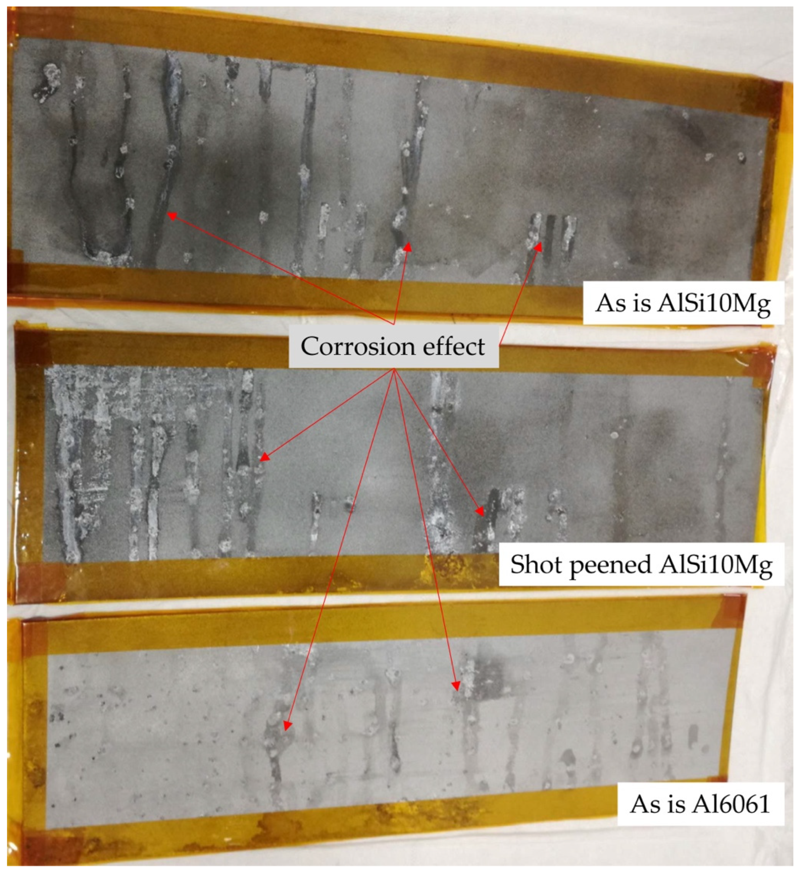
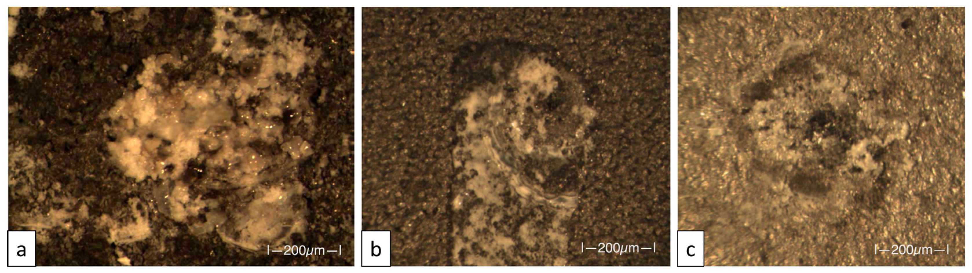
3.1. Salt-Spray Test

The main test is the verification of corrosion resistance by salt-spray test of the sol–gel silica-based coating, applied on one side of the three following specimens as-is AlSi10Mg specimen, shot-peened AlSi10Mg specimen, and as-is Al6061 specimen.
In Figure 2, these three specimens, before the salt-spray test, are shown. Some peculiar features of SLM technology can be identified: For the as-is AlSi10Mg, the speckled appearance of the surface is due to microgeometrical defect aggregates (satellites, trapped powders, etc.), and these issues are much less evident on the shot-peened specimen, where the scanning lines of the SLM process arose. The speckled appearance is less obvious on the third specimen due to the different aluminum alloy characterized by a different light-diffusion property than that expected for an SLMed surface characterized by high energy. In fact, the higher energy density employed for the processing lowered the surface roughness [33]; as a consequence, the multiple surface reflections were reduced, and the scattering was improved in all directions [34].
The same specimens, after the salt-spray test, can be observed in Figure 3. On the side protected by the silica coating, it was observed that a browning of the surfaces is more noticeable for the as-is AlSi10Mg specimen, milder for the shot-peened AlSi10Mg specimen, and almost absent for the as-is Al6061 specimen.
All specimens passed the salt-spray tests, with no signs of corrosion on the surface after 168 h, the darkening phenomena of the coating could be due to the fact that the coating was added with functionalizing elements to increase heat transfer [35].
The evaluation of the other side of the specimens (not treated by the coating) although not of interest was left for comparison in order to highlight the improved effect, in terms of surface protection (Figure 4).
Figure 5 shows, in detail, this side for the investigated specimens. The as-is AlSi10Mg exhibits a marked irregular corrosion phenomenon (Figure 5a) after the 168 h test. The same material subjected to the shot-peening is characterized by a more regular corrosion attack, as shown in Figure 5b; this is probably due to the stress-induced damage, which triggers a more localized beginning of the corrosion [36]. Analogously, the Al6061 surface is affected by a local crater with regular rims (Figure 5c) ascribable to the employed Volumetric Energy Density (VED), greater than the AlSi10Mg case, and resulting in increased defects on the fabricated surfaces [37].
A more in-depth analysis of coated surfaces, i.e., side “A”, allows us to investigate how the coating was effective on different surface morphologies. Figure 6a shows the as-is AlSi10Mg, which is characterized by a number of bumps; it is well-known that the balling phenomenon, i.e., a protrusion of material in the form of balls caused by the Maragoni effect, is typical of SLM process because of the high temperature gradients, which lead to a high surface tension gradient [38]. Between the bumps, some salt deposits were trapped without altering the corrosion capability of the coated surface. These phenomena are enhanced on the shot-peened AlSi10Mg surfaces: the mechanical action of the glass-sphere impacts increases the probability to have local damages, which can be observed in the dark regions in Figure 6b; also, the light small area comprises salt crystals that are incorporated into the bumpy surface [39,40]. Total different behavior is observed on the Al6061 specimen, where the balling phenomenon is marginal, and a small circular porosity is visible on the surface (Figure 6c). The previously mentioned browning areas are present on all the specimens and are apparently due to defects initially present on the fabricated part; however, by zooming into a particular area of these zones (Figure 6d), it may be assumed that there was a reaction between the coating pigment and some intermetallic components coming from the SLM process. In fact, it is well-known that the high-energy laser consolidation can produce a wide range of microstructures and promote reaction intermediates of the elements that compose the alloy [38].

3.2. Adhesion Test

This test aims to assess the capability of a relatively ductile coating film to adhere to a metallic substrate. The removal of pressure-sensitive tape over cuts made in the coating may cause damages which are classified according to the standardized method ASTM D3359-23 [41]. The results observed on the coated surfaces showed a very good adhesion result for quite all the not-machined specimens, whilst a lower capability was detected for the machined ones. In Table 2, the results are presented according to the classification codes and with respect to the percent area removed.
The as-is AlSi10Mg returned 5B classification, meaning that no area was removed for both the machined and non-machined status. Figure 7a shows one of these cases that is characterized by excellent outcomes with high repeatability. The shot-peened specimen made of the same material exhibited, in one case, some issues: Specimen 5 was characterized by a good performance of the non-machined surface, whilst wide detachments, greater than 65%, were detected on the machined one; also, Specimen 6 exhibited a small number of defects in both the conditions. Regarding the Al6061, only the machined surface, in one case, resulted in a 3B classification, meaning that between 5 and 15% of the area was removed.

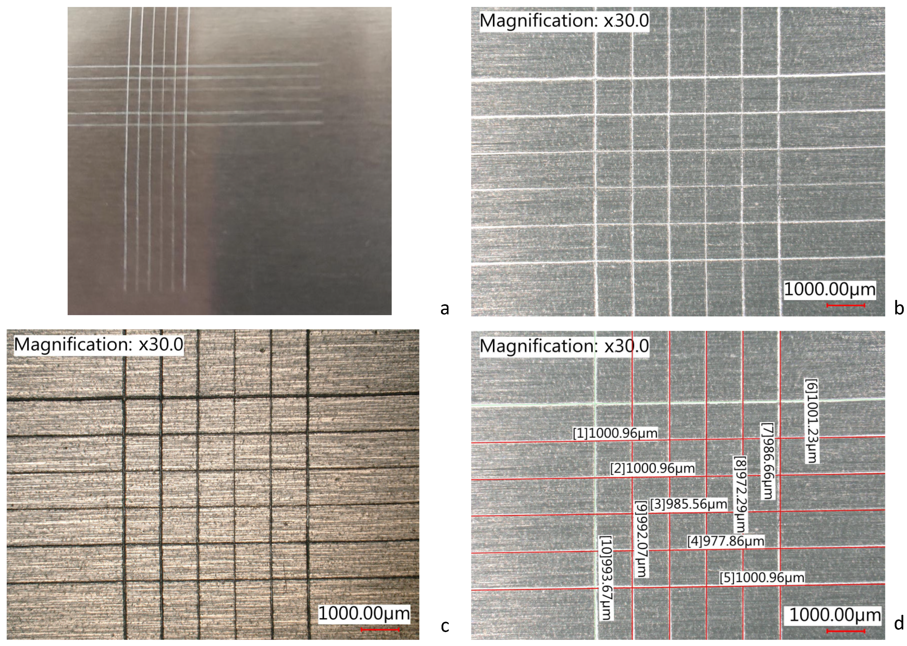
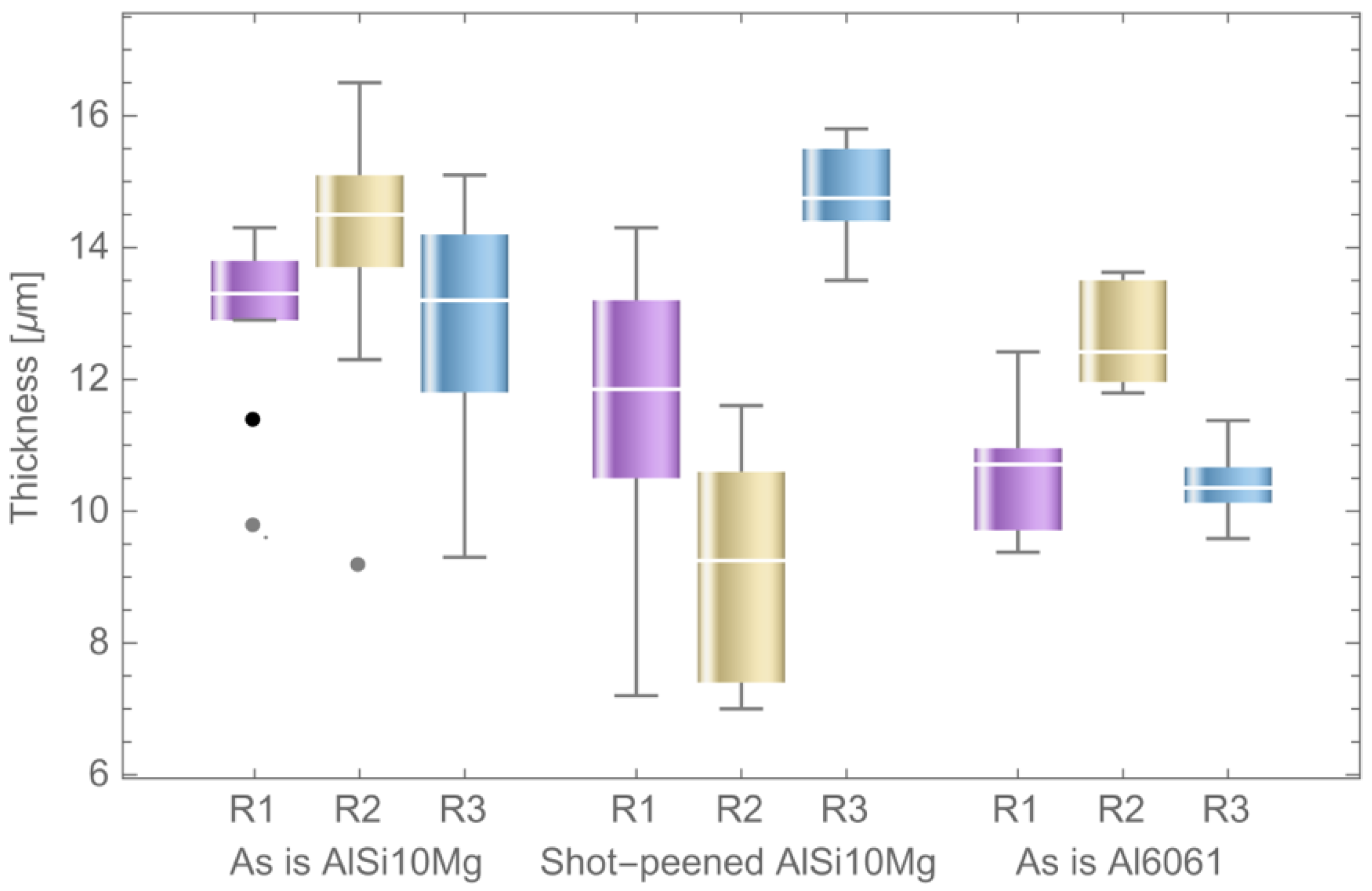
3.3. Thickness Analysis

The test, based on magnetic induction, was carried out on 140 × 100 × 2 mm3 specimens. Ten measurements were taken that were uniformly distributed over the entire surface.
The results are reported in Table 3. A marked scattering is observed for surfaces fabricated in SLM, as expected. In fact, the attainable roughness for an SLMed aluminum part is in the range of 5–8 µm for horizontal surfaces, and the peak-to-valley height can reach 40 µm. As a consequence, the coating reflects this variability, and a higher average thickness is obtained to cover the profile well. A thinner coating is observed for machined areas characterized by a roughness, Ra, in the range of 0.8–1.2 µm.
The data trends are described by the box-and-whiskers charts reported in Figure 8 and Figure 9 for rough and machined areas, respectively. The as-is AlSi10Mg shows a big scattering of thickness but good repeatability. The shot-peened surface is characterized by a lower variability since many particles and satellites were removed from the surface; however, the coating’s average thickness is bigger. In this case, some outliers (i.e. the points lying outside 1.5 times the interquartile range) are observed in the first replicate, meaning that some dips can be related to the dark areas shown in Figure 6b. The as-is Al6061 shows a better surface finishing due to the higher VED, which leads to a smoother surface. In this case, the found outliers can be attributed to the typical SLM defects due to the balling effects, which increase with a high processing energy.
The coating thicknesses measured on machined surfaces are markedly smaller than the rough ones. Figure 9 shows the outcomes for different replicates and specimens. The AlSi10Mg is characterized by good repeatability, with some bottom outliers, meaning some defects, such as an SLM porosity which is not completely filled by the coating. The repeatability is good since the median variation is less than 1 µm. Conversely, the shot-peened specimens exhibit a greater scattering of data, with distributions positioned 5 µm apart. This can be due to the mechanical action the shot-peening can induce on the surface [42,43]. Low variability is observed for the as-is Al6061 without outliers.
As a conclusive remark, expected differences are observed between rough and machined surfaces. Different variabilities between materials and surface conditions can be included. The as-is AlSi10Mg shows the worst result, with a scattering in the measure of an interquartile more than 20 µm. Other rough specimens have an interquartile of about 10 µm. This is markedly reduced for machined surfaces (3 µm). Considering that the application was manually performed, we can assess that the deposition is sufficiently homogeneous.

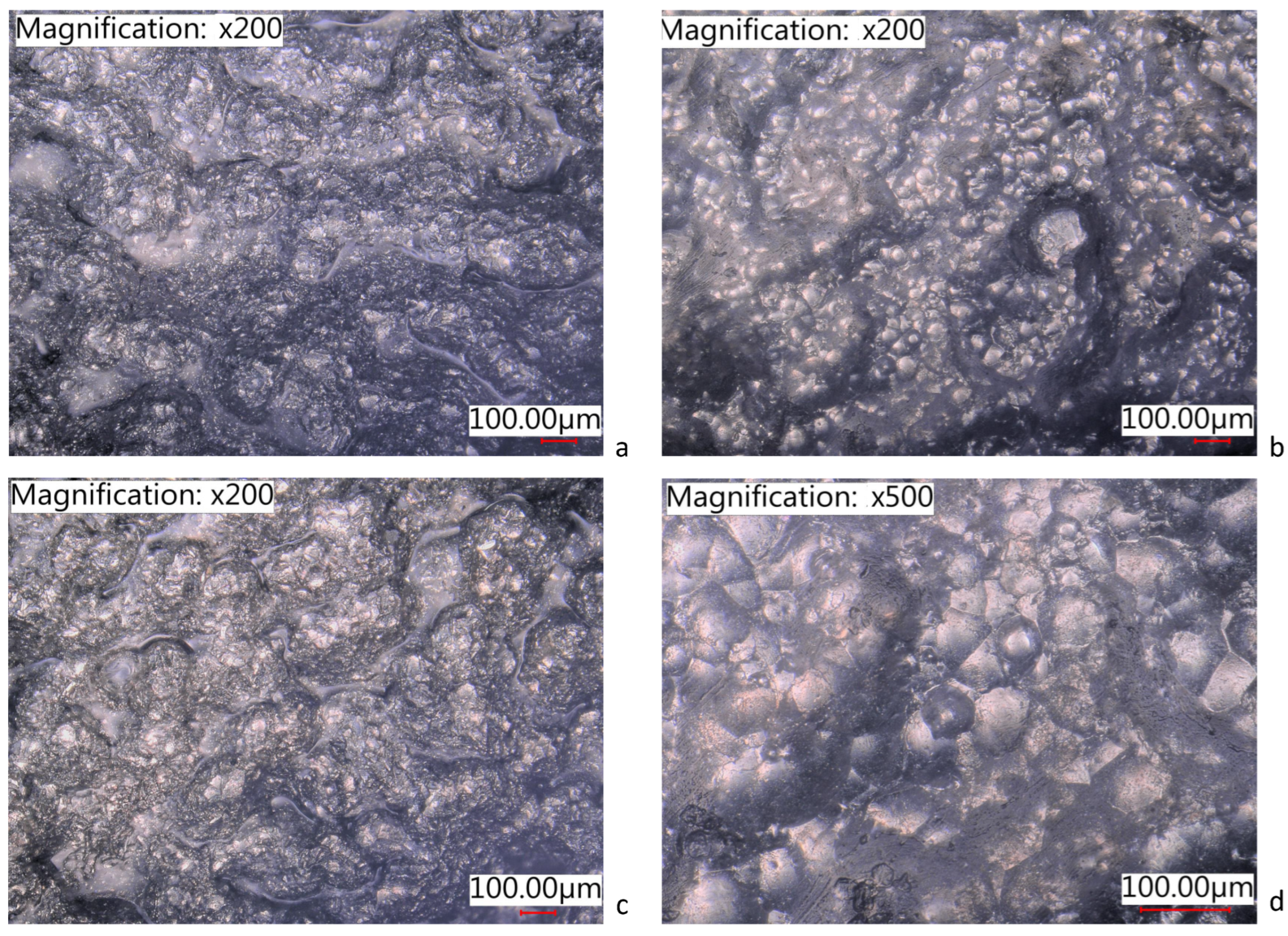
3.4. Neutral Salt-Spray Test

This test is designed to measure the resistance of a component to the exposure of salt. Test: A typical effect on aluminum is the surface damages and corrosion degradations, which may be observed by inspection with the naked eye. According to the standard, the test was performed for four days. A 24-h spray of a 5% salt solution was performed. The temperature was monitored, and it did not exceed the range of 35 ± 0.1 °C. The drying was provided for 24 h, and then the specimens went back into the chamber for a 5% salt spray for another 24 h. Finally, they came out and were subjected to another 24-h dry. The specific weight of the solution was measured each day and was in the range of 1.0341 ± 0.001 kg/dm3, with a pH ranging between 6.9 and 7. Figure 10 shows one of the repetitions for each specimen type. This test was brilliantly passed by all the specimens: no alteration, no corrosion attack, and no local damage were observed on all the surfaces, whether machined or rough.

3.5. Determination of Thermal Cycling Resistance

A thermal cycle through two temperature extremes was applied to the coated specimens to assess the suitability for service in severe conditions. This accelerated laboratory testing can damage the coating because of the increased stress coming from the expansion and contraction of the substrate with a different coefficient of expansion from the coating, leading to crack formation and early failure [44]. Rapid ramps are applied for this purpose. The previously described procedure was applied. The temperature values were monitored, leading to the trends reported in Figure 11.
At the end of the cycle, a photograph was taken of each specimen, and a visual inspection was achieved to verify the presence of macro-defects on the surfaces.
Figure 12 shows the results for the investigated specimens. The as-is AlSi10Mg passed the test, with no or negligible defects (Figure 12a). Conversely, the shot-peened AlSi10Mg ones were characterized by dark areas and matting (Figure 12b). Minor issues were found on the Al6061, which was affected by some halos (Figure 12c).
The damaged areas were measured and are reported in Figure 13. The as-is AlSi10Mg, which was fabricated by using standard EOS exposure parameters, maintained its surface morphology till the end of the thermal cycle both for rough and machined zones. A slight increase of the defect is notable for the latter since the machining can increase the surface’s residual stress. The shot-peened AlSi10Mg exhibited an average defected area of 16% and 11% for rough and machined specimens, respectively. This is attributed to the stress induced by the finishing operation, which reduces the material capacity to resist the additional severe expansion and compression cycle. The machined surfaces, in this case, show a better result, probably due to the partial elimination of the stress-induced zone by machining. The as-is Al6061 fabricated by high VED exhibits an intermediate behavior with about 5% defected area. This is an important indication about the selection of the exposure parameters in the SLM fabrication: the enhancing of the surface roughness by selecting a higher energy density can limit the ability of the coated surface to resist high thermal cycles. The surface stresses, in this case, are not reduced if machining is applied. In fact, the damaged area is 8% of the total specimen’s surface.

4. Conclusions

Nanostructured silica sol–gel protective coatings demonstrated excellent chemical stability and corrosion resistance, and they can be applied in very thin layers that can effectively protect SLM-manufactured parts thanks to the filling characteristics of the coating. This peculiarity makes nanostructured silica sol–gel an excellent candidate for the protection of Selective Laser Melting as-built surfaces. In fact, the non-coated SLM surfaces exhibit aggressive corrosion, as shown in the salt-spray test. This research highlights some distinctive features depending upon the aluminum alloy and the surface conditioning post fabrication. The rough as-is AlSi10Mg showed very good results for the adhesion and thermal-cycle tests, but a large scattering in the coating thickness measurement was observed. This material, subjected to preliminary shot-peening, is affected by a stress-induced condition which reduces the performances achieved in the salt-spray test and in the thermal cycle. The better surface properties achieved by high VED in the SLM fabrication of as-is Al6061 specimens were attributed to the good results in the thickness analysis and adhesion test; however, the salt spray and thermal cycle pointed out some small defects after the testing. The machined specimens were characterized by a very small average coating thickness, as expected, but in some cases, the adhesion capability was reduced. The machining allowed a slight increase in the thermal-cycle capability; however, the opposite behavior was detected for shot-peened specimens.
Silica sol–gel coating is an environmentally friendly surface-protection technique and has the potential to replace the highly toxic chromium-based galvanic treatments traditionally used to increase the corrosion resistance of metals. In particular, aluminum parts protected with silica sol–gel coatings can be seamlessly integrated into circular economy cycles.

Author Contributions

Conceptualization, L.M., A.B. and L.B.; Methodology, A.B. and L.B.; Validation, D.P.; Investigation, L.M. and G.L.F.; Writing—original draft preparation, L.M.; Writing—review & editing, D.P., A.B., L.B. and C.M. All authors have read and agreed to the published version of the manuscript.

Funding

This research received no external funding.

Institutional Review Board Statement

Not applicable.

Informed Consent Statement

Not applicable.

Data Availability Statement

Not applicable.

Conflicts of Interest

The authors declare no conflict of interest.

References

  1. Yao, X.; Zhou, J.; Lin, Y.; Li, Y.; Yu, H.; Liu, Y. Smart manufacturing based on cyber-physical systems and beyond. J. Intell. Manuf. 2019, 30, 2805–2817. [Google Scholar] [CrossRef] [Green Version]
  2. Levitt, T. The Globalization of Markets. Harvard Business Review, May–June 1983; 92–102. [Google Scholar]
  3. Elshkaki, A. The implications of material and energy efficiencies for the climate change mitigation potential of global energy transition scenarios. Energy 2023, 267, 126596. [Google Scholar] [CrossRef]
  4. Yang, M.; Chen, L.; Wang, J.; Msigwa, G.; Osman, A.I.; Fawzy, S.; Rooney, D.W.; Yap, P.-S. Circular economy strategies for combating climate change and other environmental issues. Environ. Chem. Lett. 2023, 21, 55–80. [Google Scholar] [CrossRef]
  5. Wang, C.; Tang, J.; Yu, H.; Wang, Y.; Li, H.; Xu, S.; Li, G.; Zhou, Q. Microplastic Pollution in the Soil Environment: Characteristics, Influencing Factors, and Risks. Sustainability 2022, 14, 13405. [Google Scholar] [CrossRef]
  6. Sajjad, M.; Huang, Q.; Khan, S.; Khan, M.A.; Liu, Y.; Wang, J.; Lian, F.; Wang, Q.; Guo, G. Microplastics in the soil environment: A critical review. Environ. Technol. Innov. 2022, 27, 102408. [Google Scholar] [CrossRef]
  7. Gibson, I.; Rosen, D.W.; Stucker, B.; Khorasani, M. Additive Manufacturing Technologies; Springer: New York, NY, USA, 2021; ISBN 978-3-030-56127-7. [Google Scholar] [CrossRef]
  8. Westerweel, B.; Basten, R.J.; Van Houtum, G.J. Traditional or Additive Manufacturing? Assessing Component Design Options through Lifecycle Cost Analysis. Eur. J. Oper. Res. 2018, 2270, 570–585. [Google Scholar] [CrossRef] [Green Version]
  9. Yang, S.; Tang, Y.; Zhao, Y.F. A new part consolidation method to embrace the design freedom of additive manufacturing. J. Manuf. Process. 2015, 20, 444–449. [Google Scholar] [CrossRef] [Green Version]
  10. Debnath, B.; Shakur, M.S.; Tanjum, F.; Rahman, M.A.; Adnan, Z.H. Impact of Additive Manufacturing on the Supply Chain of Aerospace Spare Parts Industry—A Review. Logistics 2022, 6, 28. [Google Scholar] [CrossRef]
  11. Peng, T.; Kellens, K.; Tang, R.; Chen, C.; Chen, G. Sustainability of additive manufacturing: An overview on its energy demand and environmental impact. Addit. Manuf. 2018, 21, 694–704. [Google Scholar] [CrossRef]
  12. Colorado, H.; Velásquez, E.; Monteiro, S. Sustainability of additive manufacturing: The circular economy of materials and environmental perspectives. J. Mater. Res. Technol. 2020, 9, 8221–8234. [Google Scholar] [CrossRef]
  13. Green, J.A. Aluminum Recycling and Processing for Energy Conservation and Sustainability; ASM International: Materials Park, OH, USA, 2007. [Google Scholar]
  14. Nordheim, E.; Barrasso, G. Sustainable development indicators of the European aluminium industry. J. Clean. Prod. 2007, 15, 275–279. [Google Scholar] [CrossRef]
  15. Fontaras, G.; Samaras, Z. On the way to 130gCO2/km—Estimating the future characteristics of the average European passenger car. Energy Policy 2010, 38, 1826–1833. [Google Scholar] [CrossRef]
  16. Yan, Q.; Song, B.; Shi, Y. Comparative study of performance comparison of AlSi10Mg alloy prepared by selective laser melting and casting. J. Mater. Sci. Technol. 2020, 41, 199–208. [Google Scholar] [CrossRef]
  17. Trevisan, F.; Calignano, F.; Lorusso, M.; Pakkanen, J.; Aversa, A.; Ambrosio, E.P.; Lombardi, M.; Fino, P.; Manfredi, D. On the Selective Laser Melting (SLM) of the AlSi10Mg Alloy: Process, Microstructure, and Mechanical Properties. Materials 2017, 10, 76. [Google Scholar] [CrossRef] [PubMed] [Green Version]
  18. Schneller, W.; Leitner, M.; Springer, S.; Grün, F.; Taschauer, M. Effect of HIP Treatment on Microstructure and Fatigue Strength of Selectively Laser Melted AlSi10Mg. J. Manuf. Mater. Process. 2019, 3, 16. [Google Scholar] [CrossRef] [Green Version]
  19. Tommasi, A.; Maillol, N.; Bertinetti, A.; Penchev, P.; Bajolet, J.; Gili, F.; Pullini, D.; Mataix, D.B. Influence of Surface Preparation and Heat Treatment on Mechanical Behavior of Hybrid Aluminum Parts Manufactured by a Combination of Laser Powder Bed Fusion and Conventional Manufacturing Processes. Metals 2021, 11, 522. [Google Scholar] [CrossRef]
  20. Osborne, J.H. Observations on chromate conversion coatings from a sol–gel perspective. Prog. Org. Coat. 2001, 41, 280–286. [Google Scholar] [CrossRef]
  21. Zhang, X.; van den Bos, C.; Sloof, W.G.; Hovestad, A.; Terryn, H.; de Wit, J. Comparison of the morphology and corrosion performance of Cr(VI)- and Cr(III)-based conversion coatings on zinc. Surf. Coat. Technol. 2005, 199, 92–104. [Google Scholar] [CrossRef]
  22. Apte, A.; Tare, V.; Bose, P. Extent of oxidation of Cr(III) to Cr(VI) under various conditions pertaining to natural environment. J. Hazard. Mater. 2006, 128, 164–174. [Google Scholar] [CrossRef]
  23. Asgari, H.; Baxter, C.; Hosseinkhani, K.; Mohammadi, M. On microstructure and mechanical properties of additively manufactured AlSi10Mg_200C using recycled powder. Mater. Sci. Eng. A 2017, 707, 148–158. [Google Scholar] [CrossRef]
  24. Brinker, C.J.; Scherer, G.W. Sol-Gel Science: The Physics and Chemistry of Sol-Gel Processing; Academic Press: Boston, MA, USA, 1990. [Google Scholar] [CrossRef]
  25. Mutin, P.H.; Vioux, A. Nonhydrolytic processing of oxide-based materials: Simple routes to control homogeneity, morphology, and nanostructure. Chem. Mater. 2009, 21, 582–596. [Google Scholar] [CrossRef]
  26. Liu, Y.; Sun, D.Z.; You, H.; Chun, J.S. Corrosion resistance properties of organic-inorganic hybrid coatings on 2024 aluminum alloy. Appl. Surf. Sci. 2005, 246, 82–89. [Google Scholar] [CrossRef]
  27. Zheludkevich, M.L.; Serra, R.; Montemor, M.F.; Salvado, I.M.M.; Ferreira, M.G.S. Corrosion protective properties of nanostructured sol–gel hybrid coatings to AA2024-T3. Surf. Coat. Technol. 2006, 200, 3084–3094. [Google Scholar] [CrossRef]
  28. Vreugdenhil, A.J.; Balbyshev, V.N.; Donley, M.S. Nanostructured silicon sol-gel surface treatments for Al 2024-T3 protection. J. Coat. Technol. 2001, 73, 35–43. [Google Scholar] [CrossRef]
  29. Voevodin, N.N.; Kurdziel, J.W.; Mantz, R. Corrosion protection for aerospace aluminum alloys by Modified Self-assembled NAnophase Particle (MSNAP) sol–gel. Surf. Coat. Technol. 2006, 201, 1080–1084. [Google Scholar] [CrossRef]
  30. ASTM B117-19; Standard Practice for Operating Salt Spray (Fog) Apparatus; Book of Standards Volume: 03.02. American National Standards Institute: Washington, DC, USA, 2019. [CrossRef]
  31. ISO 9227:2017; Corrosion Tests in Artificial Atmospheres—Salt Spray Tests. ISO: Geneva, Switzerland, 2017.
  32. ASTM D3322-82(2017); Standard Practice for Testing Primers and Primer Surfacers Over Preformed Metal; Book of Standards Volume: 06.02. ASTM: West Conshohocken, PA, USA, 2017. [CrossRef]
  33. Yang, T.; Liu, T.; Liao, W.; MacDonald, E.; Wei, H.; Chen, X.; Jiang, L. The influence of process parameters on vertical surface roughness of the AlSi10Mg parts fabricated by selective laser melting. J. Mater. Process. Technol. 2019, 266, 26–36. [Google Scholar] [CrossRef]
  34. Whitehouse, D.J. Handbook of Surface and Nanometrology; CRC Press: Boca Raton, FL, USA, 2010. [Google Scholar] [CrossRef]
  35. Wu, L.; Baghdachi, J. Functional Polymer Coatings: Principles, Methods, and Applications; John Wiley & Sons, Inc.: New York, NY, USA, 2015. [Google Scholar] [CrossRef]
  36. Tan, M.Y. Localized Corrosion in Complex Environments; John Wiley & Sons: New York, NY, USA, 2023. [Google Scholar]
  37. Giovagnoli, M.; Silvi, G.; Merlin, M.; Di Giovanni, M.T. Optimisation of process parameters for an additively manufactured AlSi10Mg alloy: Limitations of the energy density-based approach on porosity and mechanical properties estimation. Mater. Sci. Eng. A 2021, 802, 140613. [Google Scholar] [CrossRef]
  38. Gu, D. Laser Additive Manufacturing of High-Performance Materials; Springer: Berlin/Heidelberg, Germany, 2015. [Google Scholar] [CrossRef]
  39. Vargel, C. Corrosion of Aluminium, 2nd ed.; Elsevier Science: Amsterdam, The Netherlands, 2020. [Google Scholar] [CrossRef]
  40. During, E.D.D. Corrosion Atlas—A Collection of Illustrated Case Histories, 3rd ed.; Elsevier: Amsterdam, The Netherlands, 2018. [Google Scholar]
  41. ASTM D3359-23; Standard Test Methods for Rating Adhesion by Tape Test. ASTM: West Conshohocken, PA, USA, 2023. [CrossRef]
  42. Uzan, N.E.; Ramati, S.; Shneck, R.; Frage, N.; Yeheskel, O. On the effect of shot-peening on fatigue resistance of AlSi10Mg specimens fabricated by additive manufacturing using selective laser melting (AM-SLM). Addit. Manuf. 2018, 21, 458–464. [Google Scholar] [CrossRef]
  43. Maamoun, A.H.; Elbestawi, M.A.; Veldhuis, S.C. Influence of Shot Peening on AlSi10Mg Parts Fabricated by Additive Manufacturing. J. Manuf. Mater. Process. 2018, 2, 40. [Google Scholar] [CrossRef] [Green Version]
  44. Doerner, M.F.; Nix, W.D. Stresses and deformation processes in thin films on substrates. Crit. Rev. Solid State Mater. Sci. 2006, 14, 225–268. [Google Scholar] [CrossRef]
Figure 1. Partially machined AlSi10Mg specimen for additional tests.
Coatings 13 01081 g001
Figure 2. As-is AlSi10Mg, shot-peened AlSi10Mg, and as-is Al6061 specimens before test.
Coatings 13 01081 g002
Figure 3. As-is AlSi10Mg, shot-peened AlSi10Mg, and as-is Al6061 specimens after 168 h salt-spray test.
Coatings 13 01081 g003
Figure 4. Aspects of non-coated surfaces of the tested specimens after 168 h salt-spray test.
Coatings 13 01081 g004
Figure 5. Corrosion results after 168 h salt-spray test of not coating side “B” for as-is AlSi10Mg (a), shot-peened AlSi10Mg (b), and Al6061 (c).
Coatings 13 01081 g005
Figure 6. Corrosion results after 168 h salt-spray test of coated side “A” for as-is AlSi10Mg (a), shot-peened AlSi10Mg (b), Al6061 (c), and 500× shot-peened AlSi10Mg (d).
Coatings 13 01081 g006
Figure 7. Adhesion test specimens for as-is AlSi10Mg (a), 30× magnification AlSi10Mg (b), 30× magnification with polarized light (c), and grid measurement (d).
Coatings 13 01081 g007
Figure 8. Box-and-whiskers chart of thickness measurements for rough surfaces.
Coatings 13 01081 g008
Figure 9. Box-and-whiskers chart of thickness measurements for machined surfaces.
Coatings 13 01081 g009
Figure 10. Specimens after neutral salt-spray test: as-is AlSi10Mg (a), shot-peened AlSi10Mg (b), and as-is Al6061 (c).
Coatings 13 01081 g010
Figure 11. Measured temperature values during the thermal-cycle test.
Coatings 13 01081 g011
Figure 12. Specimen after the thermal-cycling resistance test: as-is AlSi10Mg (a), shot-peened AlSi10Mg (b), and as-is Al6061 (c).
Coatings 13 01081 g012
Figure 13. Damaged areas after thermal-cycle test for investigated specimens.
Coatings 13 01081 g013
Table 1. Employed SLM process parameters for the two considered alloys.
SLM Process ParametersEnergy Density (J/mm3)
Laser Power
(W)
Scan Speed (mm/s)Hatch Distance (mm)Layer Thickness (mm)
AlSi10Mg37013000.190.0349.9
Al6061-RAM235014000.110.0375.8
Table 2. Adhesion-test results for the investigated specimens.
SpecimenIDMachinedClassificationPercent Area Removed
As-is AlSi10Mg1No5B0%, none
As-is AlSi10Mg2No5B0%, none
As-is AlSi10Mg3No5B0%, none
Shot-peened AlSi10Mg 4No5B0%, none
Shot-peened AlSi10Mg 5No5B0%, none
Shot-peened AlSi10Mg 6No2B15%–35%
Al60617No5B0%, none
Al60618No5B0%, none
Al60619No5B0%, none
As-is AlSi10Mg1Yes5B0%, none
As-is AlSi10Mg2Yes4B0%, none
As-is AlSi10Mg3Yes5B0%, none
Shot-peened AlSi10Mg 4Yes5B0%, none
Shot-peened AlSi10Mg 5Yes0BGreater than 65%
Shot-peened AlSi10Mg 6Yes4BLess than 5%
Al60617Yes5B0%, none
Al60618Yes3B5%–15%
Al60619Yes5B0%, none
Table 3. Measurement of coating thicknesses for investigated specimens at rough and machined areas.
SpecimenIDThickness in the Rough Area (µm)Thickness in the Machined Area (µm)
As-is AlSi10MgT128, 17.1, 50, 39.2, 84, 56.8, 40.8, 28.1, 32.9, 57.612.9, 11.4, 13.8, 13.5, 9.8, 13.9, 13.8, 13.1, 14.3, 12.9
As-is AlSi10MgT251.5, 31.5, 29.8, 32.8, 42.9, 42.1, 37.7, 45.1, 57.9, 4314.9, 14.3, 14.2, 15.5, 15.1, 13.7, 12.3, 14.7, 16.5, 9.2
As-is AlSi10MgT331.9, 19.4, 32, 41.3, 39.9, 19.6, 60.2, 38.9.3, 11.3, 11.8, 14.7, 13.6, 14.2, 15.1, 12.9, 12.5, 13.5
Shot-peened AlSi10Mg T461.8, 53, 50.3, 53.7, 47.8, 50.6, 30.7, 35, 48.9, 46.910.5, 11.1, 11.9, 10.1, 13.2, 11.8, 12.2, 14.3, 13.8, 7.2
Shot-peened AlSi10Mg T555.2, 42.8, 56.9, 48.5, 50.6, 73.1, 69.2, 58.3, 41.2, 59.79.9, 8.6, 10.6, 8.3, 11.6, 7, 11, 7.2, 9.9, 7.4
Shot-peened AlSi10Mg T654.4, 59.9, 38.5, 42.1, 58.8, 43.7, 41.8, 54.3, 54.4, 50.914, 13.5, 14.8, 15.4, 14.4, 15.5, 14.7, 15.6, 15.8, 14.4
Al6061T732, 26.5, 29.5, 45.5, 29.8, 26.4, 36.4, 34.5, 29.9, 28.712.4, 10.9, 11.1, 10.2, 10.7, 9.7, 10. 7, 9.4,10.7, 9.6
Al6061T835.7, 35.1, 60.8, 31.4, 39, 33.9, 53.4, 30.5, 32.1, 33.413.6, 12.5, 13.5, 11.8, 13.6, 11.9, 13.0, 12.2, 12.3, 11.9
Al6061T932.6, 26.2, 31.7, 31.3, 23.3, 29.8, 27.1, 33, 40.7, 19.810.4, 10.7, 10.9, 10.6, 10.2, 10.3, 9.6, 11.4, 10.1, 9.9
Disclaimer/Publisher’s Note: The statements, opinions and data contained in all publications are solely those of the individual author(s) and contributor(s) and not of MDPI and/or the editor(s). MDPI and/or the editor(s) disclaim responsibility for any injury to people or property resulting from any ideas, methods, instructions or products referred to in the content.

