Article

Characterization of Two Types of Polylactic Acid Coating Loaded with Gentamicin Sulphate Deposed on AZ31 Alloy

by
Manuela Elena Voicu
1,
Daniela Ionita
1,
George-Octavian Buica
1,
Doina Draganescu
2,
Valentina Anuta
3,
Florentina Monica Raduly
4 and
Ioana Demetrescu
1,5,*
1
Department of General Chemistry, Faculty of Chemical Engineering and Biotechnologies, University Politehnica of Bucharest, 313 Splaiul Independentei, 060042 Bucharest, Romania
2
Department of Pharmaceutical Physics and Informatics, “Carol Davila” University of Medicine and Pharmacy, 020956 Bucharest, Romania
3
Department of Physical and Colloidal Chemistry, “Carol Davila” University of Medicine and Pharmacy, 020956 Bucharest, Romania
4
National Institute for Research and Development in Chemistry and Petrochemistry—ICECHIM, Splaiul Independentei No. 202, 6th District, 060021 Bucharest, Romania
5
Academy of Romanian Scientists, 3 Ilfov Street, 050044 Bucharest, Romania
*
Author to whom correspondence should be addressed.
Coatings 2023, 13(6), 1105; https://doi.org/10.3390/coatings13061105
Submission received: 9 May 2023 / Revised: 10 June 2023 / Accepted: 14 June 2023 / Published: 15 June 2023

Abstract

:
This paper compares two types of polylactic acid (PLA) coating on AZ31 alloy obtained by dip coating and electrospinning. Both types of coating were loaded with gentamicin sulphate (GS) and the drug-loading efficiency and release were assessed. A higher encapsulation and release efficiency of GS was seen for dip coating (73% and 49.53%, respectively) compared to nanofiber coating (65% and 12.37%, respectively). Furthermore, the antibacterial effect of the samples with and without GS was assessed using Gram-negative (Escherichia coli) and Gram-positive (Staphylococcus aureus) bacteria, showing that the samples with the drug encapsulated are more resistant to bacteria than the other samples. The electrochemical data reveal a higher stability in the SBF of the surface obtained by dipping than that obtained by electrospinning. The PLA coating shows a porosity of 46% for the sample obtained through dip coating and 32% for nanofibers, which is in accordance with the BET analysis results. Moreover, a higher adhesion strength was obtained for AZ31-PLA-dip (4.99 MPa) than for the AZ31-PLA-nanofibers (1.66 MPa). All samples were structurally, morphologically, and topographically characterized.

1. Introduction

It is well known that stainless steel, CoCr alloys, and Ti alloys have been used intensively as metallic biomaterials across various applications [1]. Their biocompatibility [2] and ability to osseointegrate indicate their firm anchorage as a surgical implant, revealed by the growth of bone around them, together with good corrosion resistance [3] in bioliquids. These qualities allow the above materials to be recommended for long-term implantation within the human body [4]. For temporary implants such as plates, screws, and wires used to repair fractured bones, the desirable properties of biocompatibility, a low density, and a high specific strength can be found in biodegradable magnesium and its alloys [5,6,7,8]. The low corrosion resistance [9], apparently a demerit can be changed into an advantage in the field of implants, due to their biodegradability [10]. Additionally, the use of various coatings [8,11,12] and surface modifications [13] offers promising avenues for controlling and addressing this characteristic. A classification of coatings [8] as a function of the procedures of elaboration introduced mechanical, physical, chemical, and biological methods, each with numerous representatives. It is worth mentioning that thin film deposition, such as the magnetron sputtering method, is able to improve tribological properties based on a hydroxyapatite thick coating, which has shown an increase in the Ca/P ratio from 1.83 to 1.97 [14]. Composition is another way to divide coatings, and furthermore, the classification based on their functions [15] introduced antibacterial coatings, drug loading [16] self-healing [17], and self-sacrificing examples. Of course, some of them are dual-functional [18] or multi-functional with synergic efficiency. For example, it is also important to mention various nanostructures that can be loaded with bioactive molecules [19] or drugs, leading to better bioperformance [20,21,22,23]. In a time when there are very aggressive bacteria, most of them leading to implant failure and the dangerous development of infections, it is useful to develop an investigation into loading drugs with antibacterial effects, which could help future metallic biomaterials’ treatment. Frequently, Gram-negative and Gram-positive bacteria are used for testing antibacterial activity such as model bacteria Escherichia coli and Staphylococcus aureus, respectively. Knowing that Staphylococcus aureus is one of the causes of nosocomial wound infections [24] and its presence increases the frequency of methicillin-resistant Staphylococcus aureus (MRSA) in hospitals, the present research has importance and motivation to try to select a better coating for temporary implants where the corrosion rate can be monitored. It is important to mention that the selected positive bacterium is a member of the priority target group for the study named ESKAPE pathogens [25], which contains six highly virulent, antibiotic, and very aggressive resistant bacterial pathogens. As a starting point, the present research involved two different procedures of polylactic acid (PLA) coating depositions, and for both types of elaborated samples, the same characterization was performed including the microstructure, electrochemical stability, adhesion, drug loading and release, and antibacterial effect. Compared with analogs, PLA coatings are eco-friendly, biodegradable, lightweight, and hydrophobic with antibacterial properties [26].
The percentage of gentamicin sulphate (GS) efficiency loading and the kinetic of drug release for both types of coatings were established and discussed in connection with their antibacterial effects.

2. Materials and Methods

2.1. Reagents

AZ31 alloy (96 wt% Mg, 3 wt% Al, and 1 wt% Zn—Alfa Aesar, Thermo Fisher, Kandel, Germany), polylactic acid (PLA—GoodFellow, Huntingdon, UK) in a mixture with chloroform (CHCl3 99%—Carl Roth, Germany), and N,N-dimethylformamide (DMF 99%—Alfa Aesar, Haverhill, MA, USA) were used to modify the AZ31 alloy surface. Simulated body fluid (SBF) was prepared according to Kokubo procedure [27]. Purified water (18.2 MΩcm−1) was used to prepare the aqueous solutions. Gentamicin sulphate (GS) powder (Alfa Aesar, Thermo Fisher, Kandel, Germany) was used as a drug in a solution of phosphate-buffered saline (PBS) of pH 7.4 (NaCl 8 g/L, KCl 0.2 g/L, NaHPO4 1.42 g/L, KH2PO4 0.24 g/L—purchased from Sigma-Aldrich, Saint Louis, MO, USA). A Luria Bertani medium (10 g/L peptone, 5 g/L yeast extract, 5 g/L NaCl) helped bacteria grow for antibacterial effect.

2.2. Equipment

A high-power source (PS/EJ30P20—Glassman High Voltage, Inc., High Bridge, NJ, USA) connected to a pump (Legato 180—KD Scientific, Holliston, MA, USA) and KSV NIMA (Biolin Scientific, Espoo, Finland) were used to modify the AZ31 with nanofibers and film coating, respectively.
Scanning electron microscopy (SEM—Hitachi TM4000plus tabletop, Hitachi High-Tech Corp., Tokyo, Japan) was used to determine the morphology of the samples AZ31 coated with electrospun nanofibers, coated by dip, and encapsulated with GS.
UV 1720 spectrometer (Uvison Technologies Ltd., Kent, UK) was used to record the UV-VIS spectra using a quartz cuvette with 1 cm length path.
Fourier-transform infrared spectroscopy (FT-IR—Perkin-Elmer Spectrum 100, Perkin-Elmer, Shelton, DC, USA) was used to characterize the PLA coating with and without GS.
Electrochemical measurements were performed on a potentiostat–galvanostat (AutoLAB PGSTAT100N—Metrohm Autolab, Barendrecht, The Netherlands) in a three electrode electrochemical cell. The AZ31 sample coated with PLA was used as the working electrode (6 mm in diameter), Ag/AgCl, 3M KCl system was used as the reference electrode, and Pt wire was used as the counter electrode. The electrolyte was the SBF solution. Electrochemical impedance spectroscopy (EIS) was performed at opened circuit potential (OCP) with a 10 mV amplitude, in the range frequencies 104–10−1 Hz. Potentiodynamic voltammetry (Tafel plots) vs. OCP at 2 mV/s.
An adhesion tester (DeFelsko, Ogdensburg, New York, NY, USA) by pull-off was used to determine the adhesion of the PLA coatings.
Specific surface area and pore distribution were measured using a porosimeter Nova 2200e Quantachrome by nitrogen adsorption/desorption, at 77 K.
A Millipore Direct Q 3UV system (Merck, Molsheim, France, 18.2 MΩcm−1) was used as a source of purified water.

2.3. Procedures

2.3.1. PLA Deposition on AZ31

Despite the trends in using alternative methods of deposition [28], our paper used simple electrochemical procedures. Before PLA deposition, the AZ31 alloy samples (20 mm × 20 mm × 1 mm) were gradually polished with SiC paper up to #4000 followed by ultrasonic cleaning with ultrapure water (5 min) and ethanol (5 min) then air dried.
The deposition of PLA on AZ31 alloy was performed by dipping and electrospinning methods. The solution of PLA used in the deposition process was obtained by dissolving 1.23 g of PLA granules in a mixture of CHCl3 and DMF in a ratio of 1:1.5 (v/v) under magnetic stirring and alternating ultrasonic bathing until a homogeneous mixture was obtained.
AZ31 surface modified with PLA nanofibers was obtained through electrospinning following the previously described procedure [20]. Briefly, the PLA solution placed in a 1 mL plastic syringe situated at a distance of 15 cm from sample AZ31 was connected to a peristaltic pump (0.5 mL/h) and a voltage source set at 20 kV for 1 h.
The dip-coating process involved soaking AZ31 in PLA solution at a constant speed of 120 mm/min and maintaining it for 1 min, then they were removed from the bath with the same speed. The coated samples were dried at room temperature.

2.3.2. Drug Loading–Release and Antibacterial Effect

The coated samples were immersed in 10 mL of 2 g/L GS solution, prepared in PBS at pH 7.4.
The sorption of GS on AZ31 coated with PLA was followed for 24 h, similar to other investigations in drug encapsulation cases performed with antibiotics known for their effect on both Gram-positive and Gram-negative microorganisms [29,30]. The procedure used UV-VIS spectrometry at 203 nm wavelength.
The encapsulated efficiency (EE %) of gentamicin was calculated using Equation (1) [31]:
EE   % = The   amount   of   drug   loaded Theorical   drug   amount   in   the   PLA   coating · 100
The release of GS from the electrospun nanofibers and those dip-coated was determined in triplicate by placing the AZ31 samples encapsulated with GS in 10 mL PBS (pH 7.4), and UV-VIS spectra at different periods were recorded (a linear dependence of GS concentration on absorbance with the equation of Abs = 0.0105 + 5.922 × 10⁻⁴C, R2 = 0.9990 was used).
The antibacterial activity of AZ31 uncoated and coated through both methods was evaluated using Escherichia coli and Staphylococcus aureus.
Before testing, bacteria were grown in Luria Bertani medium [32] at 37 °C. The samples were incubated for 24 h in a solution that contained a medium of culture, and the optical density was determined at 600 nm wavelength. The growth inhibition index is used to determine the I %, as follows [33]:
I   % = [ C 24 C 0 T 24 T 1 / C 24 C 0 ] · 100
where:
T0—time 0 h, the negative control in the presence of the sample;
T24—time 24 h, the negative control in the presence of the sample;
C0—time 0 h, the blank optical density of the positive control;
C24—time 24 h, the blank optical density of the positive control.

3. Results and Discussion

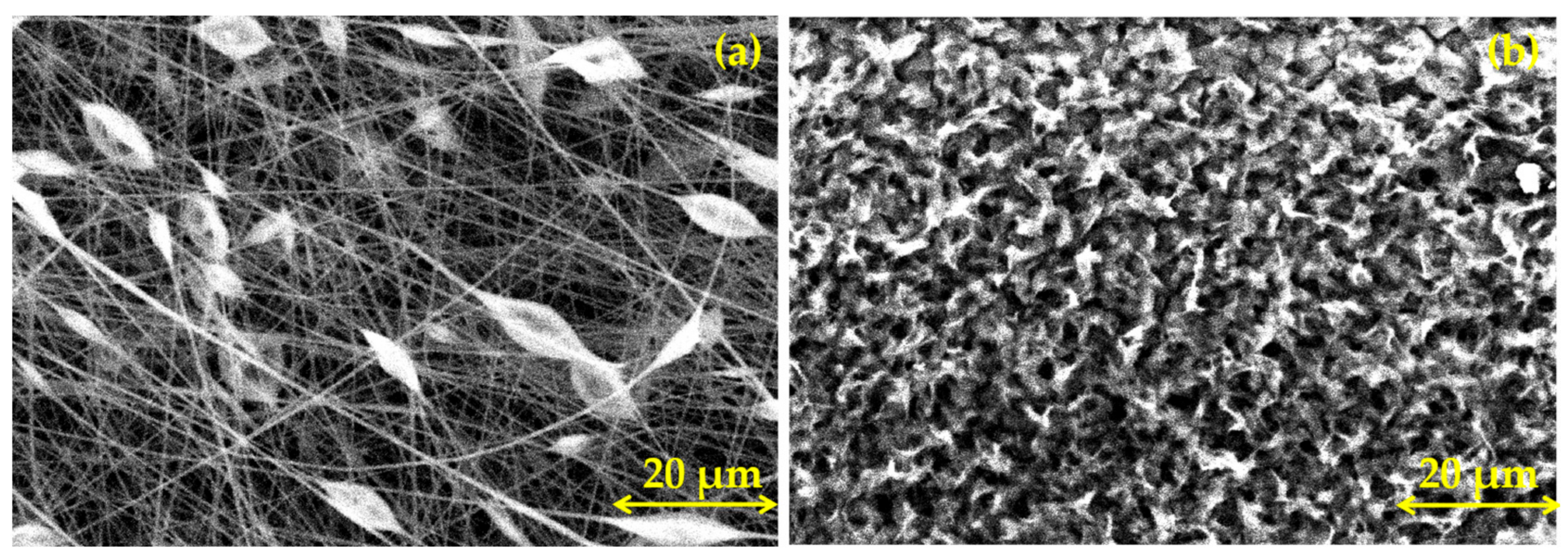
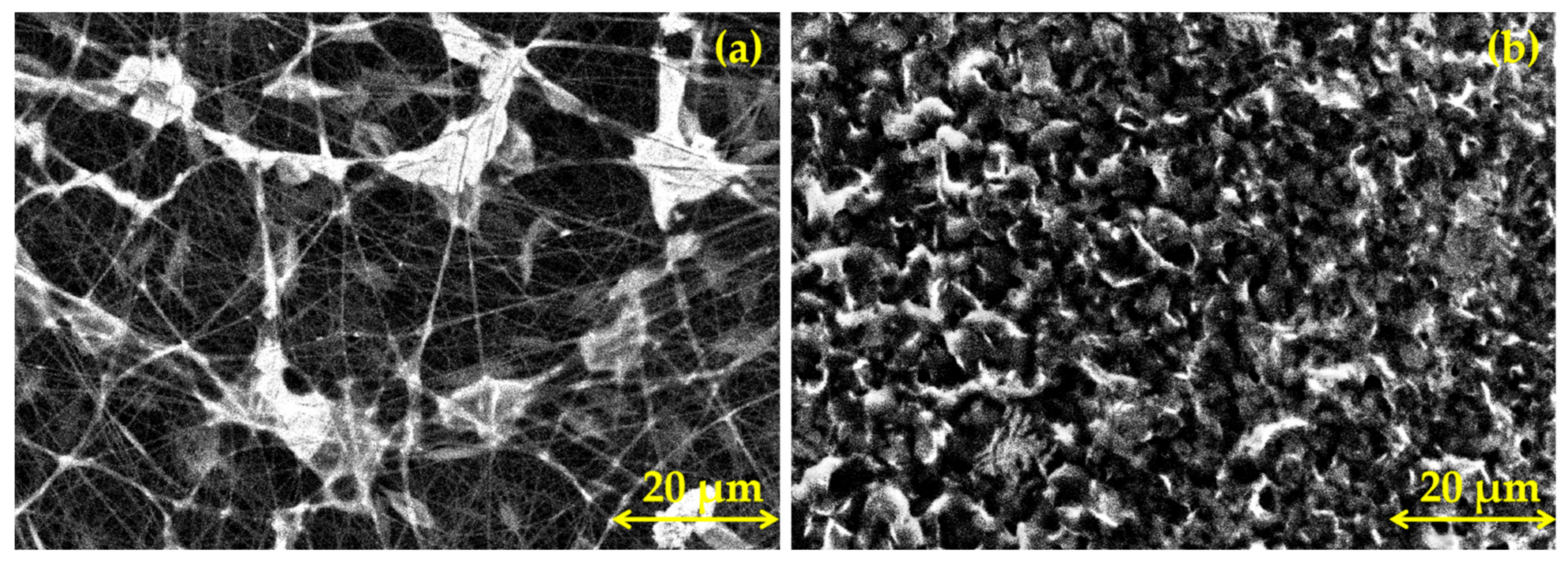
3.1. Morphological Characterization of PLA Coatings

The SEM micrography of AZ31 alloy coated with PLA nanofibers (Figure 1a) reveals that the surface is completely coated with randomly arranged nanofibers with diameters of around 500 nm. Beads with lengths of around 5 to 10 µm formed at the surface, probably caused by the solvent having not sufficiently evaporated when the solution landed on the surface of the alloy. In the case of AZ31 alloy coated with PLA by dip coating (Figure 1b), the resulting surface is uniformly coated with PLA structures and pores with diameters of around 1–1.5 µm.

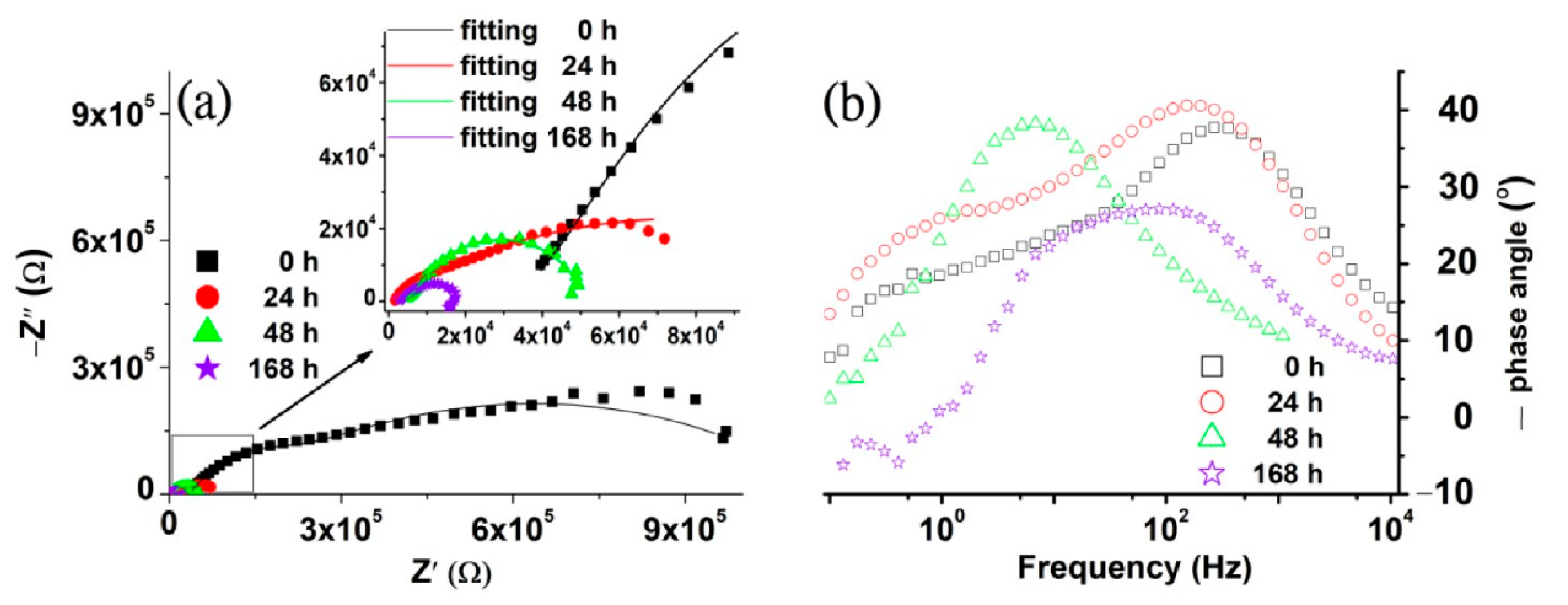
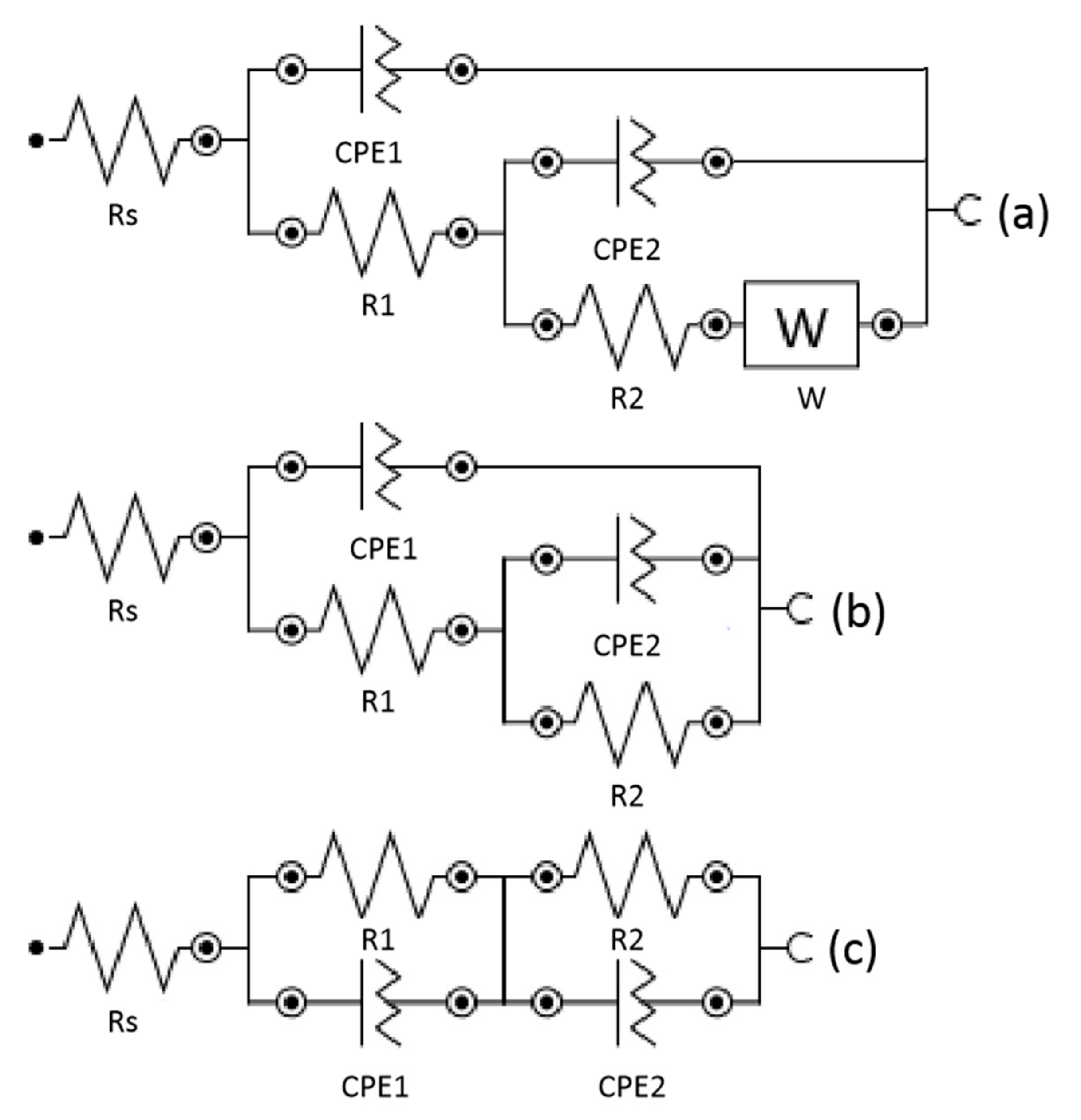
3.2. Electrochemical Characterization

Potentiodynamic polarization tests (Tafel plots) and electrochemical impedance spectroscopy (EIS) were carried out to investigate the corrosion of the AZ31 coated with PLA. The electrochemical experiments were performed in the SBF solution [24] at pH 7.4.
To investigate the corrosion resistance of coated AZ31 alloy, a potentiodynamic test was performed. The corrosion potentials (Ecorr) at different immersion periods on the SBF of AZ31 coated by electrospinning shifted towards more positive values when compared with AZ31 uncoated [18]. This suggest that the coating with PLA increases the electrochemical stability of the AZ31 alloy. The same behaviour was observed in the case of AZ31-PLA-dip (Figure 2). However, when comparing the Ecorr of both coatings, the corrosion resistance of AZ31-PLA-dip did not show significant changes until 48 h when it considerably improved, increasing by about 330 mV. The corrosion current density (Icorr) of AZ31-PLA-nanofibers [16] was lower than AZ31-PLA-dip in the first 24 h, and after 48 h (Table 1), the values obtained were close for the two coated samples.
In addition, the percentage porosity for the AZ31-PLA samples was calculated using the following equation [34]:
P = Rp substrate Rp coating · 10 ε corr β a · 100 %
where:
Rpsubstarte is the polarization resistance of the uncoated sample (AZ31);
Rpcoating is the polarization resistance of the coating (AZ31-PLA);
Δεcorr is the difference between the substrate and coating corrosion potential;
βa is the substrate anodic curve slope.
Thus, for AZ31-PLA-dip, the porosity was 46%, while for AZ31-PLA-nanofibers, it was 32%. These results suggest that the coating obtained by dipping is more suitable for medical applications such as bone regeneration and drug delivery [35].
The Nyquist and Bode plots of the AZ31-PLA coated by dip coating and exposed in the SBF solution are shown in Figure 3a and Figure 3b, respectively. The electrochemical characteristics of AZ31 modified with PLA nanofibers obtained in the same conditions were previously described [20].
The Bode diagram indicates that the phase angle value of the dip-coated AZ31 immersed for 168 h in SBF is more positive than that of the same sample immersed at 0, 24, and 48 h. This fact suggests that there has been a decrease in corrosion resistance.
The sample of AZ31-PLA-dip is represented by two small capacitive loops for the entire time it is immersed in SBF, as shown in the equivalent circuit, which could be due to the presence of corrosion products such as MgO [36]. The corrosion products generated could increase the thickness of the coating during immersion in SBF and prevent the permeation of the electrolyte through the pores to the AZ31 substrate. The same tendency was observed for AZ31 coated with PLA nanofibers [20].
The equivalent circuit used to fit the data at 0 h of Immersion is shown in Figure 4a. In this circuit, Rs is the solution resistance; R1 and CPE1 were attributed to describe the properties of the polymer coating. Due to the existence of pores in the polymer coating, the solution can infiltrate through the film and can interact with the AZ31 substrate, a process described by Warburg diffusion (W) and the electric double layer formed at the interface. The characterization of the double layer was described by CPE2 and R2. The data acquired after 24 and 48 h of immersion were fitted with the circuit shown in Figure 4b. The absence of the Warburg impedance element describes the displacement of the air trapped in the pores of the film with electrolyte. The general attribution of elements remains the same as for 0 h. After 168 h, the SBF solution penetrates through the PLA coating reaching the AZ31–coating interface where it forms a thin film of corrosion products. During the corrosion process, the dissolved oxygen, as a depolarizing agent, needs to go through the corrosion product layer before reaching the electrode reaction interface. This process leads to the appearance of R2 in parallel with CPE2, which represent the charge transfer resistance of the corroded area at the coating–substrate interface and the double layer capacitance, respectively, in the equivalent circuit in Figure 4c. Other elements are Rs, R1, and CPE1 representing solution resistance and the polymer coating and R2 and CPE2. The fitting results are presented in Table 2.
As shown in Table 2, the R1 value decreases after 24 h by one order of magnitude. This decrease can be explained by the ingress of water and the development of new pores or micro-cracks in the coating. This phenomenon is also supported by the variation in the coating capacitance value. A lower capacitance is associated with a higher resistance of the coating. Table 2 shows a large value for the resistance of the double layer (R2) for AZ31–PLA at 0 h immersion, indicating that the electron transfer process during the corrosion is more difficult, and therefore leads to a lower corrosion reaction rate.

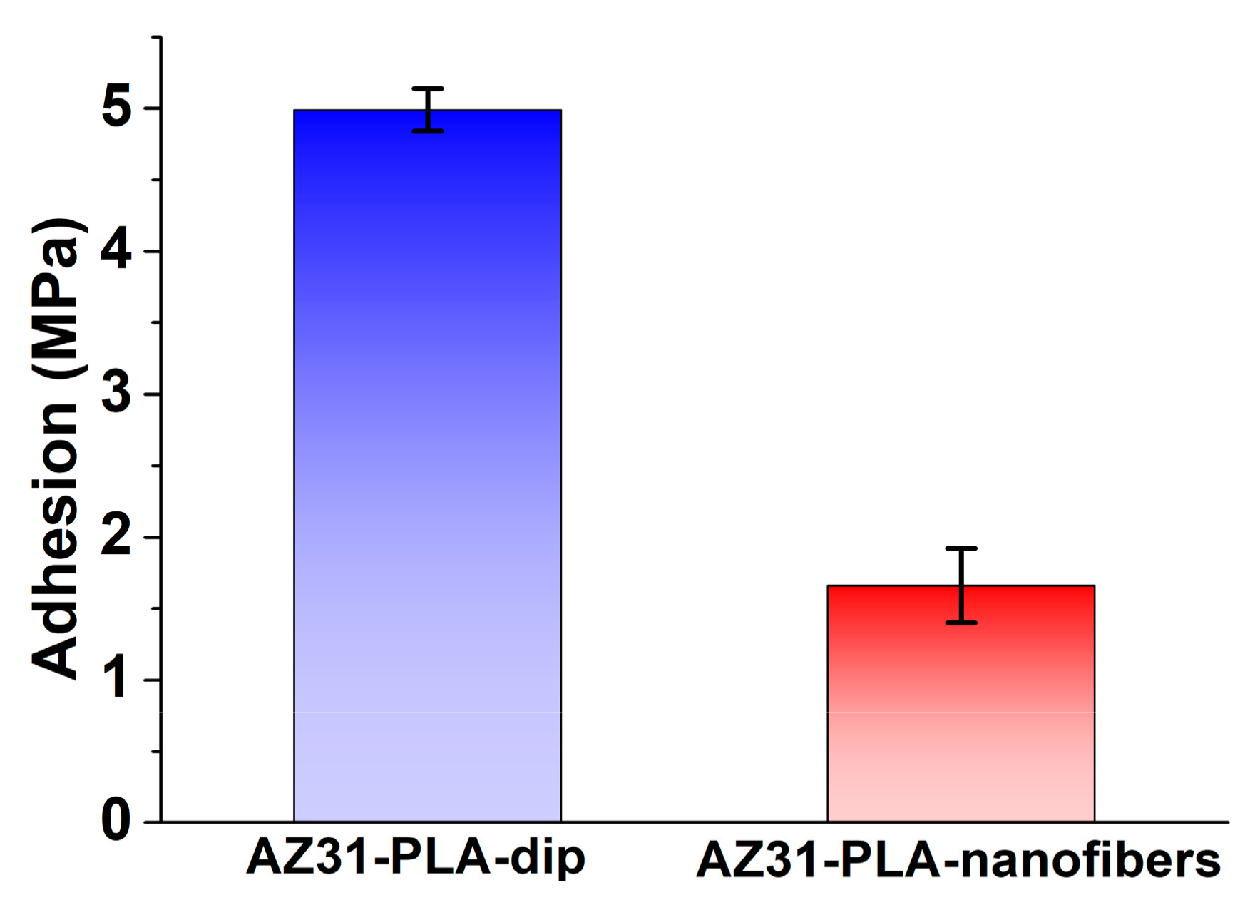
3.3. Adhesion of PLA Coatings

Figure 5 shows the adhesion of PLA coatings obtained by dip coating and electrospinning. The PLA-coated samples were fixed with double adhesive tape on aluminum dollies (14 mm diameter), grounded with 2500 grit, and the force to peel a specific area of the PLA coatings from the AZ31 substrate was measured. The values obtained were calculated by three measurements for each coated sample.
A higher adhesion strength was obtained for AZ31-PLA-dip (4.99 MPa) than for the AZ31-PLA-nanofibers (1.66 MPa). However, the adhesion strength between the coating and the substrate was not as strong as expected. The results demonstrate that the AZ31-PLA-dip had higher tensile strength and strain at failure compared to those of AZ31-PLA-nanofibers. This was due to the fact that good interfacial interactions were formed between the PLA-dip coating and Mg alloys, which might be attributed to the bonding force between the coating layer and the Mg substrate [37]. Thus, the results revealed that the dip-coating process led to a PLA coating of AZ31 with better adhesion property.

3.4. Determination of Surface Area by BET Method

The BET method was used to determine the specific surface area and pore size distribution of the PLA coatings (Table 3) based on Barrett–Joyner–Halenda (BJH) analysis. The samples were exposed to vacuum degassing for 4 h, at 130 °C. Nitrogen adsorption at a relative pressure (P/P0) of 0.99 was used to determine pore volume. Based on the average pore diameter (2–50 nm diameter), samples can be classified as mesoporous according to IUPAC.
Following the BET method measurements, the specific surface areas of AZ31-PLA-nanofibers and AZ31-PLA-dip were 12.09 and 5.43 m2/g, respectively. The average diameter of the pores of AZ31-PLA-nanofibers was 3.67 nm, close to the value of AZ31-PLA-dip (3.30 nm).
Depending on the microporous structure, the AZ31-PLA-dip creates a larger surface area and higher pore volume, which supports cellular proliferation and antibacterial activity.

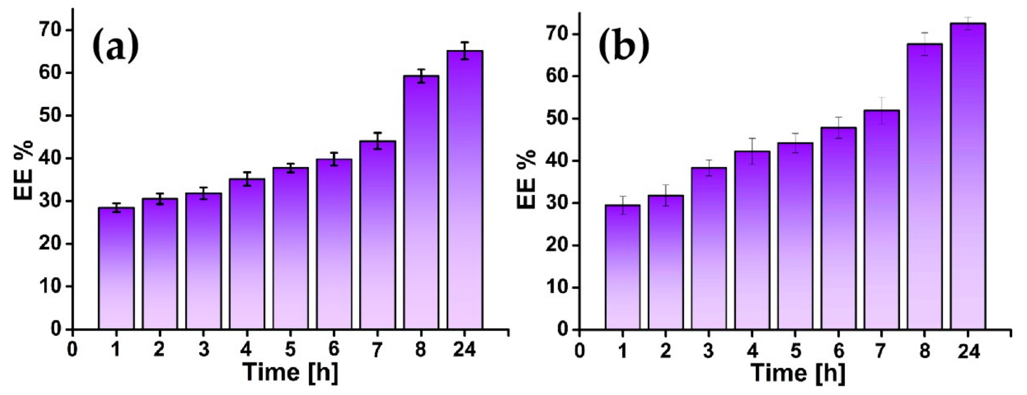
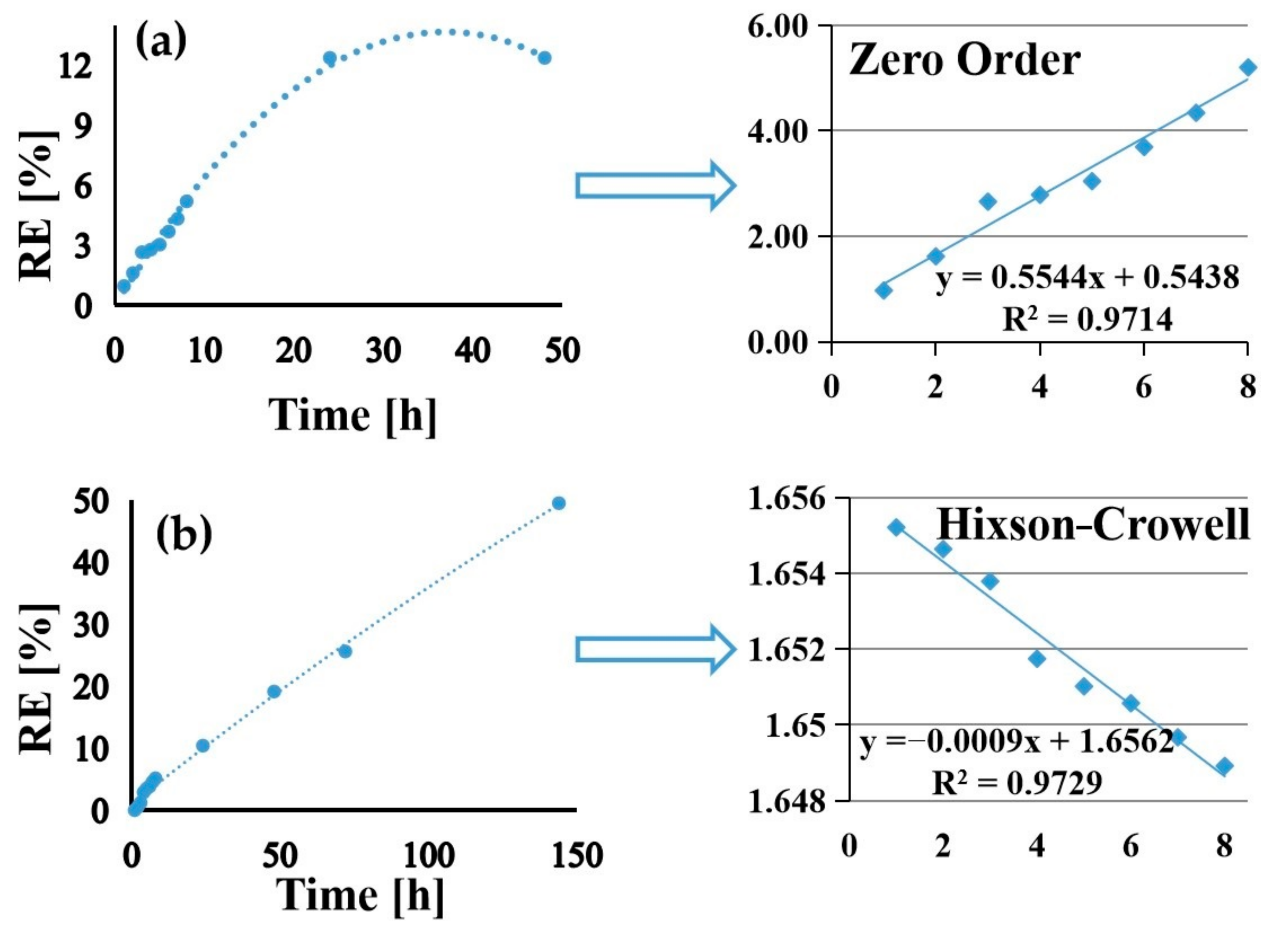
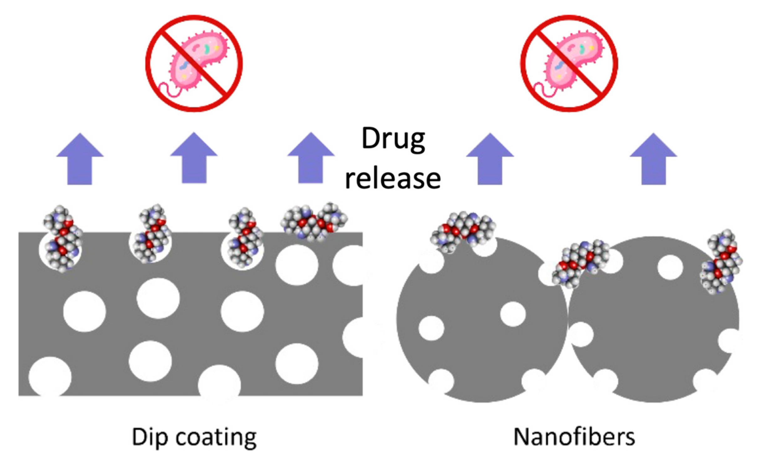
3.5. Drug Loading and Release

Gentamicin sulphate encapsulation efficiency was calculated and the results can be seen in Figure 6. The efficiency is similar for both types of samples. Small differences in encapsulation efficiency can be seen between the two sample types, with the dip-coated sample having a slightly higher value. Twenty-four hours after immersion, 73% gentamicin was encapsulated in the dip-coated sample and only 65% gentamicin was encapsulated in the nanofibers sample.
The incorporation of GS into modified AZ31 with PLA was confirmed through FT-IR analysis (Figure 7). The peaks of PLA are the following: 1752 cm−1 (–C=O), 1453 cm−1 (–C–H), 1182 cm−1 (–C–O ester), and 1085 (C–O–C), 870–756 cm−1 (–C–O stretch), confirming that AZ31 alloy was fully coated by PLA. For GS, wave numbers of 1040 and 1640 cm−1 are the typical bands assigned to the primary and secondary amides [38]. In the spectrum of AZ31-PLA-GS, groups are presented belonging to PLA coatings and the GS drug. Thus, the existence of additional GS peaks in the AZ31-PLA spectrum indicates that the GS was incorporated into the PLA coatings. Furthermore, in the AZ31-PLA-GS spectrum, the appearance of peaks with decreased intensities after the encapsulation of GS may suggest a probable chemical interaction with the GS and PLA groups.
Moreover, SEM images of the AZ31-PLA-nanofibers after the encapsulation of GS (Figure 8a) show residues from the PBS solution and GS particles as small bright dots with diameters of around 1 µm. The encapsulation of GS on AZ31-PLA-dip (Figure 8b) led to similar results as in the case of dip-coated samples, where GS particles are visible as small bright dots with diameters of around 1 µm.
The release of GS encapsulated in AZ31-PLA-nanofibers is slow during the entire process. After 24 h, a small amount of GS was released (12.37% corresponding to 161 mg/L) followed by a sustained release profile, while for the AZ31-PLA-GS-dip samples, an increased amount of GS (49.53% corresponding to 699 mg/L) was released at 144 h. The release rate is higher in the case of AZ31-PLA-GS-dip than AZ31-PLA-GS-nanofibers. This could be due to products being formed between GS and the degradation products of PLA, which slows the release [39].
The GS release data were analyzed by fitting the release profiles to various kinetics models, such as zero-order, first-order, Higuchi, Hixson–Crowell, and Peppas–Korsmeyer.
The best fitting models for AZ31-PLA-GS-nanofibers and AZ31-PLA-GS-dip were zero-order and Hixson–Crowell, respectively. The parameters of the equations for the GS release profile are shown in Table 4.
The zero-order model (Figure 9a) shows a constant drug release from polymeric nanofibers, being characteristic of the ideal concentration of the drug. The release of GS from AZ31-PLA-GS-dip structures follows the Hixson–Crowell model (Figure 9b) due to a possible change in the surface area/pores during the release process.
The value of R2 according to the results of the kinetics models is close for both models.

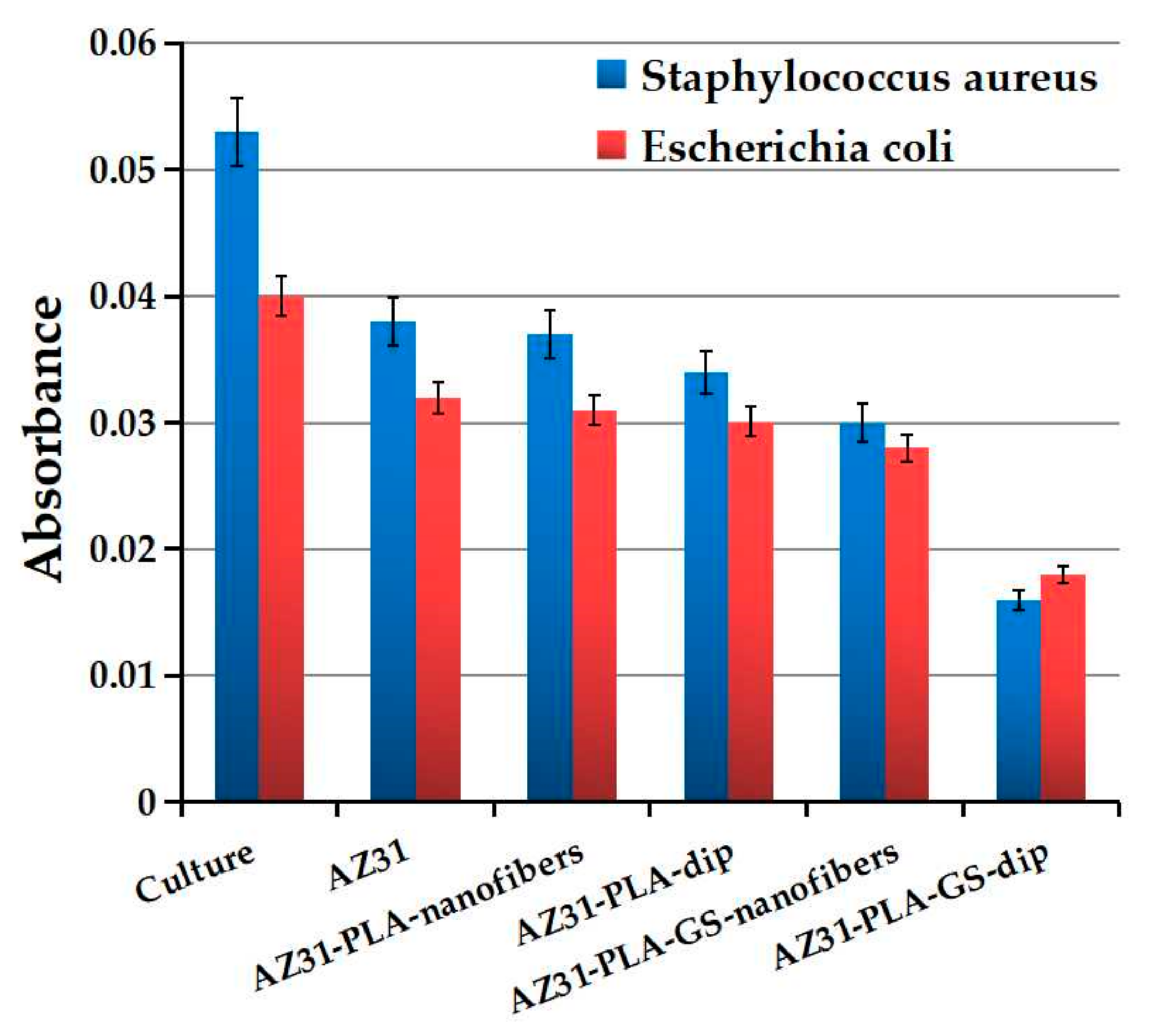
3.6. Antibacterial Effect

The antibacterial activity for AZ31-PLA samples without and with GS encapsulated was examined in Staphylococcus aureus and Escherichia coli cultures. Optical density was determined after 24 h incubation and shows a higher antibacterial effect for Staphylococcus aureus for both types of coating. Results can be seen in Figure 10.
Following the experimental data, we can determine that dip-coated samples produced a greater antibacterial effect than those coated with nanofibers. The addition of GS in both coatings increases the antibacterial effect. In the case of dip-coated samples, the antibacterial effect is doubled, and in the case of coating with nanofibers, the increase is approximately 50% (as can see in Table 5). The improvement in the antibacterial effect can be attributed to the mesoporous structure obtained on the AZ31 surface by the two coating techniques. According to the BET analysis, it was found that dip coating generated a continuous mesoporous film with more voluminous pores than in the case of nanofibers coating, thus allowing the encapsulation and subsequential release of a larger amount of gentamicin.
As can be seen in Table 5, the antimicrobial inhibition index of bacteria is higher for Staphylococcus aureus in both coating procedures. This could be explained by the differences between the cellular wall and composition [40,41] of negative and positive bacteria. Inhibition efficacy is generally influenced by three groups of factors such as (1) bacterial status including tolerance, susceptibility and resistance, biofilm, persistence, and inoculum size; (2) host factors with serum effect and microbiota; and (3) antimicrobial concentrations (mutant selection window and sub-inhibitory concentration). The main factors in the process, the status of bacteria, the host response, and the drug usage, can together produce the final result, and their smart monitoring can determine a better effect. Understanding the links between the factors of influence allows us to propose a possible empiric antibacterial mechanism for investigated coated alloys, which is presented in Figure 11.

4. Conclusions

Two types of PLA coatings were deposited on AZ31 biodegradable alloy by electrospinning and dip coating. Both coatings types were investigated and compared. The AZ31-PLA-dip coating showed higher stability and resistance to corrosion in SBF when compared to AZ31-PLA-nanofibers. In addition, a more adherent coating was attained when the dip-coating method was used to cover the AZ31 surface.
The dip-coating method led to a continuous mesoporous film with more voluminous pores than in the case of nanofiber coating, which allowed the encapsulation and release of a larger amount of gentamicin into their structure. Moreover, dip-coated samples showed a higher antibacterial effect than those coated with nanofibers, and the addition of GS in both coatings increased their antibacterial effect.
In conclusion, both types of coatings were successfully deposited on the AZ31 substrate, and the obtained results indicate that the AZ31-PLA-dip is more advantageous than AZ31-PLA-nanofibers in various medical applications. It should be noted that further investigation is required to ensure consistency in the above statement, given the limited range of materials used.

Author Contributions

Conceptualization, M.E.V., D.I. and I.D.; methodology, M.E.V., G.-O.B., F.M.R. and V.A.; software, M.E.V., G.-O.B. and F.M.R.; validation, D.I., G.-O.B. and D.D.; formal analysis, M.E.V., F.M.R. and V.A.; investigation, M.E.V., G.-O.B. and D.D.; resources, I.D. and D.I.; data curation, D.I., G.-O.B. and F.M.R.; writing—original draft preparation, M.E.V. and G.-O.B.; writing—review and editing, M.E.V., G.-O.B., I.D. and D.D.; visualization, D.I. and F.M.R.; supervision, I.D. and D.D.; project administration, M.E.V. and I.D. All authors have read and agreed to the published version of the manuscript.

Funding

This research received no external funding.

Institutional Review Board Statement

Not applicable.

Informed Consent Statement

Not applicable.

Data Availability Statement

Not applicable.

Acknowledgments

This work was funded by the European Social Fund from the Sectoral Operational Programme Human Capital 2014–2020, through the Financial Agreement with the title “Training of PhD students and postdoctoral researchers in order to acquire applied research skills—SMART”, Contract no. 13530/16.06.2022-SMIS code: 153734.

Conflicts of Interest

The authors declare no conflict of interest.

References

  1. Chen, Q.; Thouas, G.A. Metallic implant biomaterials. Mater. Sci. Eng. R Rep. 2015, 87, 1–57. [Google Scholar] [CrossRef]
  2. Ion, R.; Stoian, A.B.; Dumitriu, C.; Grigorescu, S.; Mazare, A.; Cimpean, A.; Demetrescu, I.; Schmuki, P. Nanochannels formed on TiZr alloy improve biological response. Acta Biomater. 2015, 24, 370–377. [Google Scholar] [CrossRef]
  3. Albrektsson, T.; Chrcanovic, B.; Jacobsson, M.; Wennerberg, A. Osseointegration of Implants—A Biological and Clinical Overview. JSM Dent. Surg. 2017, 2, 1022. [Google Scholar]
  4. Popa, M.; Demetrescu, I.; Vasilescu, E.; Drob, P.; Ionita, D.; Vasilescu, C. Stability of some dental implant materials in oral biofluids. Rev. Roum. Chim. 2005, 50, 399–406. [Google Scholar]
  5. Amini, A.R.; Wallace, J.S.; Nukavarapu, S.P. Short-Term and Long-Term Effects of Orthopedic Biodegradable Implants. J. Long. Term. Eff. Med. Implant. 2011, 21, 93–122. [Google Scholar] [CrossRef] [Green Version]
  6. Zheng, Y.F.; Gu, X.N.; Witte, F. Biodegradable metals. Mater. Sci. Eng. R Rep. 2014, 77, 1–34. [Google Scholar] [CrossRef]
  7. Staiger, M.P.; Pietak, A.M.; Huadmai, J.; Dias, G. Magnesium and its alloys as orthopedic biomaterials: A review. Biomaterials 2006, 27, 1728–1734. [Google Scholar] [CrossRef] [PubMed]
  8. Yin, Z.-Z.; Qi, W.-C.; Zeng, R.-C.; Chen, X.-B.; Gu, C.-D.; Guan, S.-K.; Zheng, Y.-F. Advances in coatings on biodegradable magnesium alloys. J. Magnes. Alloy. 2020, 8, 42–65. [Google Scholar] [CrossRef]
  9. Bender, S.; Goellner, J.; Heyn, A.; Boese, E. Corrosion and corrosion testing of magnesium alloys. Mater. Corros. 2007, 58, 977–982. [Google Scholar] [CrossRef]
  10. Dehghanghadikolaei, A.; Ibrahim, H.; Amerinatanzi, A.; Elahinia, M. Biodegradable magnesium alloys. In Metals for Biomedical Devices; Elsevier: Amsterdam, The Netherlands, 2019; pp. 265–289. [Google Scholar]
  11. Voicu, M.-E.; Golgovici, F. A biointerface growth at immersion of a biodegradable magnesium alloy in simulated body fluid. U.P.B. Sci. Bull. Ser. B 2020, 82, 57–68. [Google Scholar]
  12. Parau, A.C.; Dinu, M.; Cotrut, C.M.; Pana, I.; Vranceanu, D.M.; Constantin, L.R.; Serratore, G.; Marinescu, I.M.; Vitelaru, C.; Ambrogio, G.; et al. Effect of Deposition Temperature on the Structure, Mechanical, Electrochemical Evaluation, Degradation Rate and Peptides Adhesion of Mg and Si-Doped Hydroxyapatite Deposited on AZ31B Alloy. Coatings 2023, 13, 591. [Google Scholar] [CrossRef]
  13. Xu, L.; Liu, X.; Sun, K.; Fu, R.; Wang, G. Corrosion Behavior in Magnesium-Based Alloys for Biomedical Applications. Materials 2022, 15, 2613. [Google Scholar] [CrossRef] [PubMed]
  14. Dinu, M.; Ivanova, A.A.; Surmeneva, M.A.; Braic, M.; Tyurin, A.I.; Braic, V.; Surmenev, R.A.; Vladescu, A. Tribological behaviour of RF-magnetron sputter deposited hydroxyapatite coatings in physiological solution. Ceram. Int. 2017, 43, 6858–6867. [Google Scholar] [CrossRef]
  15. Li, L.-Y.; Cui, L.-Y.; Zeng, R.-C.; Li, S.-Q.; Chen, X.-B.; Zheng, Y.; Kannan, M.B. Advances in functionalized polymer coatings on biodegradable magnesium alloys—A review. Acta Biomater. 2018, 79, 23–36. [Google Scholar] [CrossRef] [PubMed]
  16. Zhao, Y.; Chen, X.; Li, S.; Zeng, R.; Zhang, F.; Wang, Z.; Guan, S. Corrosion resistance and drug release profile of gentamicin-loaded polyelectrolyte multilayers on magnesium alloys: Effects of heat treatment. J. Colloid Interface Sci. 2019, 547, 309–317. [Google Scholar] [CrossRef] [PubMed]
  17. Cui, L.-Y.; Gao, S.-D.; Li, P.-P.; Zeng, R.-C.; Zhang, F.; Li, S.-Q.; Han, E.-H. Corrosion resistance of a self-healing micro-arc oxidation/polymethyltrimethoxysilane composite coating on magnesium alloy AZ31. Corros. Sci. 2017, 118, 84–95. [Google Scholar] [CrossRef]
  18. Shadanbaz, S.; Dias, G.J. Calcium phosphate coatings on magnesium alloys for biomedical applications: A review. Acta Biomater. 2012, 8, 20–30. [Google Scholar] [CrossRef]
  19. Zhang, Z.-Q.; Yang, Y.-X.; Li, J.-A.; Zeng, R.-C.; Guan, S.-K. Advances in coatings on magnesium alloys for cardiovascular stents—A review. Bioact. Mater. 2021, 6, 4729–4757. [Google Scholar] [CrossRef]
  20. Voicu, M.E.; Demetrescu, I.; Dorobantu, A.; Enachescu, M.; Buica, G.-O.; Ionita, D. Interaction of Mg Alloy with PLA Electrospun Nanofibers Coating in Understanding Changes of Corrosion, Wettability, and pH. Nanomaterials 2022, 12, 1369. [Google Scholar] [CrossRef]
  21. Lakalayeh, G.A.; Rahvar, M.; Nazeri, N.; Ghanbari, H. Evaluation of drug-eluting nanoparticle coating on magnesium alloy for development of next generation bioabsorbable cardiovascular stents. Med. Eng. Phys. 2022, 108, 103878. [Google Scholar] [CrossRef]
  22. Gao, F.; Hu, Y.; Gong, Z.; Liu, T.; Gong, T.; Liu, S.; Zhang, C.; Quan, L.; Kaveendran, B.; Pan, C. Fabrication of chitosan/heparinized graphene oxide multilayer coating to improve corrosion resistance and biocompatibility of magnesium alloys. Mater. Sci. Eng. C 2019, 104, 109947. [Google Scholar] [CrossRef] [PubMed]
  23. Ji, X.-J.; Gao, L.; Liu, J.-C.; Wang, J.; Cheng, Q.; Li, J.-P.; Li, S.-Q.; Zhi, K.-Q.; Zeng, R.-C.; Wang, Z.-L. Corrosion resistance and antibacterial properties of hydroxyapatite coating induced by gentamicin-loaded polymeric multilayers on magnesium alloys. Colloids Surf. B Biointerfaces 2019, 179, 429–436. [Google Scholar] [CrossRef] [PubMed]
  24. Tong, S.Y.C.; Davis, J.S.; Eichenberger, E.; Holland, T.L.; Fowler, V.G. Staphylococcus aureus Infections: Epidemiology, Pathophysiology, Clinical Manifestations, and Management. Clin. Microbiol. Rev. 2015, 28, 603–661. [Google Scholar] [CrossRef] [Green Version]
  25. De Oliveira, D.M.P.; Forde, B.M.; Kidd, T.J.; Harris, P.N.A.; Schembri, M.A.; Beatson, S.A.; Paterson, D.L.; Walker, M.J. Antimicrobial Resistance in ESKAPE Pathogens. Clin. Microbiol. Rev. 2020, 33, e00181-19. [Google Scholar] [CrossRef]
  26. Luque-Agudo, V.; Gallardo-Moreno, A.M.; González-Martín, M.L. Influence of Solvent and Substrate on Hydrophobicity of PLA Films. Polymers 2021, 13, 4289. [Google Scholar] [CrossRef] [PubMed]
  27. Kim, H.M.; Miyazaki, T.; Kokubo, T.; Nakamura, T. Revised Simulated Body Fluid. Key Eng. Mater. 2000, 192–195, 47–50. [Google Scholar] [CrossRef]
  28. Schwartz, A.; Kossenko, A.; Zinigrad, M.; Gofer, Y.; Borodianskiy, K.; Sobolev, A. Hydroxyapatite Coating on Ti-6Al-7Nb Alloy by Plasma Electrolytic Oxidation in Salt-Based Electrolyte. Materials 2022, 15, 7374. [Google Scholar] [CrossRef]
  29. Gemeinder, J.L.P.; de Barros, N.R.; Pegorin, G.S.; Singulani, J.d.L.; Borges, F.A.; Del Arco, M.C.G.; Giannini, M.J.S.M.; Almeida, A.M.F.; Salvador, S.L.d.S.; Herculano, R.D. Gentamicin encapsulated within a biopolymer for the treatment of Staphylococcus aureus and Escherichia coli infected skin ulcers. J. Biomater. Sci. Polym. Ed. 2021, 32, 93–111. [Google Scholar] [CrossRef]
  30. Voicu, M.E.; Draganescu, D.; Anuta, V.; Stoian, A.B.; Ionita, D.; Demetrescu, I. The interrelationship between the drug embedded TiZr surface properties and antibacterial effect. Farmacia 2022, 70, 1064–1071. [Google Scholar] [CrossRef]
  31. Eren Boncu, T.; Ozdemir, N. Electrospinning of ampicillin trihydrate loaded electrospun PLA nanofibers I: Effect of polymer concentration and PCL addition on its morphology, drug delivery and mechanical properties. Int. J. Polym. Mater. Polym. Biomater. 2022, 71, 669–676. [Google Scholar] [CrossRef]
  32. Jira, J.; Rezek, B.; Kriha, V.; Artemenko, A.; Matolínová, I.; Skakalova, V.; Stenclova, P.; Kromka, A. Inhibition of E. coli Growth by Nanodiamond and Graphene Oxide Enhanced by Luria-Bertani Medium. Nanomaterials 2018, 8, 140. [Google Scholar] [CrossRef] [PubMed] [Green Version]
  33. Jaiswal, S.; Duffy, B.; Jaiswal, A.K.; Stobie, N.; McHale, P. Enhancement of the antibacterial properties of silver nanoparticles using β-cyclodextrin as a capping agent. Int. J. Antimicrob. Agents 2010, 36, 280–283. [Google Scholar] [CrossRef] [PubMed] [Green Version]
  34. Vardaki, M.; Ionita, D.; Stoian, A.B.; Demetrescu, I. Increasing corrosion resistance of a ZrTi alloy with a bioinspired coating with low porosity. Mater. Corros. 2017, 68, 988–994. [Google Scholar] [CrossRef]
  35. Alizadeh-Osgouei, M.; Li, Y.; Vahid, A.; Ataee, A.; Wen, C. High strength porous PLA gyroid scaffolds manufactured via fused deposition modeling for tissue-engineering applications. Smart Mater. Med. 2021, 2, 15–25. [Google Scholar] [CrossRef]
  36. Shi, P.; Niu, B.; Shanshan, E.; Chen, Y.; Li, Q. Preparation and characterization of PLA coating and PLA/MAO composite coatings on AZ31 magnesium alloy for improvement of corrosion resistance. Surf. Coat. Technol. 2015, 262, 26–32. [Google Scholar] [CrossRef]
  37. Gungor, B.; Esen, Ş.; Gök, A.; Yılmaz, H.; Malazgirt, Z.; Leblebicioğlu, H. Comparison of the adherence of E. coli and S. aureus to ten different prosthetic mesh grafts: In vitro experimental study. Indian J. Surg. 2010, 72, 226–231. [Google Scholar] [CrossRef] [Green Version]
  38. Cavalu, S.; Roiu, G.; Pop, O.; Heredea, D.A.P.; Costea, T.O.; Costea, C.F. Nano-Scale Modifications of Amniotic Membrane Induced by UV and Antibiotic Treatment: Histological, AFM and FTIR Spectroscopy Evidence. Materials 2021, 14, 863. [Google Scholar] [CrossRef] [PubMed]
  39. Muñoz, M.; Torres, B.; Mohedano, M.; Matykina, E.; Arrabal, R.; López, A.J.; Rams, J. PLA deposition on surface treated magnesium alloy: Adhesion, toughness and corrosion behaviour. Surf. Coat. Technol. 2020, 388, 125593. [Google Scholar] [CrossRef]
  40. Parent, M.; Magnaudeix, A.; Delebassée, S.; Sarre, E.; Champion, E.; Viana Trecant, M.; Damia, C. Hydroxyapatite microporous bioceramics as vancomycin reservoir: Antibacterial efficiency and biocompatibility investigation. J. Biomater. Appl. 2016, 31, 488–498. [Google Scholar] [CrossRef]
  41. Li, J.; Xie, S.; Ahmed, S.; Wang, F.; Gu, Y.; Zhang, C.; Chai, X.; Wu, Y.; Cai, J.; Cheng, G. Antimicrobial Activity and Resistance: Influencing Factors. Front. Pharmacol. 2017, 8, 364. [Google Scholar] [CrossRef] [Green Version]
Figure 1. SEM micrography for (a) AZ31-PLA-nanofibers; (b) AZ31-PLA-dip.
Coatings 13 01105 g001
Figure 2. Tafel plots of AZ31 coated with PLA by dipping at different immersion times in SBF.
Coatings 13 01105 g002
Figure 3. Nyquist (a) and Bode (b) diagrams for AZ31-PLA-dip, immersed in SBF solution, in time.
Coatings 13 01105 g003
Figure 4. Equivalent circuit from (a) 0 h; (b) 24 and 48 h; (c) 168 h of immersion in SBF solution of AZ31-PLA-dip.
Coatings 13 01105 g004
Figure 5. Adhesion between PLA coatings and AZ31 substrate.
Coatings 13 01105 g005
Figure 6. Encapsulated efficiency of (a) AZ31-PLA-nanofibers, and (b) AZ31-PLA-dip.
Coatings 13 01105 g006
Figure 7. FT-IR spectra of GS-loaded PLA coatings.
Coatings 13 01105 g007
Figure 8. SEM micrography for (a) AZ31-PLA-GS-nanofibers; (b) AZ31-PLA-GS-dip.
Coatings 13 01105 g008
Figure 9. Release rate of GS from (a) AZ31-PLA-nanofibers; (b) AZ31-PLA-dip.
Coatings 13 01105 g009
Figure 10. Antibacterial activity of the AZ31 samples.
Coatings 13 01105 g010
Figure 11. Antibacterial mechanism of AZ31-PLA.
Coatings 13 01105 g011
Table 1. Tafel parameters for AZ31-PLA-dip samples.
Time
(h)
Ecorr
(V)
Icorr
(µA)
Vcorr
(µm/Year)
Rp
(Ω)
Βa
(V/Decade)
Βc
(V/Decade)
0−1.500.0725.681.25 × 1060.420.41
24−1.440.52741.60.11 × 1060.200.37
48−1.240.14911.780.34 × 1060.190.29
168−1.060.25920.390.36 × 1060.660.32
Table 2. The fitting results of EIS spectra of AZ31-PLA-dip.
Time
(h)
Rs
(kΩ)
R1
(kΩ)
CPE1R2
(kΩ)
CPE2
YO
(µMho)
N1YO
(µMho)
N2
032.310205.460.881500.0370.821
241.531529.480.92515.11.650.66
482.6120610.40.805423.350.733
1683.5824014.500.84230.83.000.545
Table 3. BET analysis values.
SampleSurface Area (BJH Method) (m2/g)Total Pore Volume
(cm3/g)
Pore Diameter (nm)Microporous Surface
(m2/g)
Volume of Micropores (cm3/g)
PLA dip coating5.430.00663.3013.710.0049
PLA nanofibers12.090.00123.673.430.0012
Table 4. GS release parameters of kinetics models.
SampleZero-OrderFirst-OrderHiguchiHixson–CrowellPeppas–Korsmeyer
R2k0R2k1R2k2R2k3R2k4n
AZ31-PLA-GS-
nanofibers
0.97140.55440.97110.00570.95622.14410.94130.0940.93971.070.6
AZ31-PLA-GS-
dip
0.97140.7710.97270.00790.97013.0030.97290.00090.7571.7191.85
Table 5. I % of the AZ31 samples in the presence of bacteria medium.
SampleI %
Staphylococcus aureusEscherichia coli
AZ3128.30 ± 0.0220 ± 1.22
AZ31-PLA-nanofibers30.18 ± 0.0322.5 ± 0.68
AZ31-PLA-dip35.84 ± 1.0224.75 ± 1.16
AZ31-PLA-GS-nanofibers43.39 ± 1.3230 ± 2.2
AZ31-PLA-GS-dip69.81 ± 1.8355 ± 0.98
Disclaimer/Publisher’s Note: The statements, opinions and data contained in all publications are solely those of the individual author(s) and contributor(s) and not of MDPI and/or the editor(s). MDPI and/or the editor(s) disclaim responsibility for any injury to people or property resulting from any ideas, methods, instructions or products referred to in the content.

