Article

Microstructure of NbMoTaTiNi Refractory High-Entropy Alloy Coating Fabricated by Ultrasonic Field-Assisted Laser Cladding Process

1
School of Mechanical Engineering, Xijing University, Xi’an 710123, China
2
Department of Advanced Materials and New Energies, Iranian Research Organization for Science and Technology (IROST), Tehran 33535111, Iran
3
Department of Mechanical Engineering, Faculty of Engineering, Imam Khomeini International University, Qazvin 3414896818, Iran
4
Department of Material Engineering, South Tehran Branch, Islamic Azad University, Tehran 1459853849, Iran
5
School of Computer Science, Xijing University, Xi’an 710123, China
*
Author to whom correspondence should be addressed.
Coatings 2023, 13(6), 995; https://doi.org/10.3390/coatings13060995
Submission received: 21 April 2023 / Revised: 19 May 2023 / Accepted: 24 May 2023 / Published: 26 May 2023
(This article belongs to the Special Issue Additive Manufacturing of Metallic Components for Hard Coatings)

Abstract

:
Refractory high-entropy alloys (RHEAs) contain alloying elements with a high melting point, promising high-temperature applications due to their unique properties. In this work, laser cladding is used to prepare RHEAS based on NbMoTaTiNi. At the same time as laser cladding, the ultrasonic field is used, and then the microstructural characteristics, grain size, residual stress, wear, and hardness of the coating are evaluated. The results show that the coating is biphasic and includes the γ (Ni) and NbMoTaTiNi phase. The NbMoTaTiNi phase had a uniform distribution throughout the coating when the ultrasonic field was applied, so that when the ultrasonic field was not used, the NbMoTaTiNi powder, in addition to spreading uniformly, had the un-melting of large particles. This caused an increase in the residual tension of the coating. The conversion of columnar grains to the equiaxed, and the reduction in structural defects, were other characteristics of using the ultrasonic field. The formation of equiaxed grains with zigzag grain boundaries reduced the friction coefficient, wear volume loss, and the wear rate of the coating applied with ultrasonic.

1. Introduction

Today, with the increase in the working temperature of gas turbine components, especially in the part of the rotating blades, the need for advanced materials that can withstand the critical conditions of the blades, which include high temperature and stress, is necessary [1]. On the other hand, it is not recommended to use these blades without a coating. Ni-based superalloys have been used as the main material of gas turbine blades for many years due to their unique properties, such as high-temperature oxidation, resistance to hot corrosion, wear, creep, fatigue, and impact [2,3]. The superalloy GTD-111 is one of the newest and most widely used materials in gas turbine blades, which exhibits good mechanical properties, especially at high temperatures [4]. However, the phenomenon of softening occurs in Ni-based superalloys with an excessive increase in the working temperature of the blades. As a result, the need for high-temperature coatings that can postpone this phenomenon is inevitable [5,6]. Various metal- and ceramic-based materials have been used to coat superalloys. Taheri et al. [6] increased the creep resistance of the GTD-111 superalloy through aluminide coating. Khorram and Taheri [7] improved the wear resistance of the superalloy by applying Metco204NS (Zr2O + 8% Y2O3) ceramic coating on the IN713C superalloy using the laser cladding method. Rezayat et al. [8] improved the corrosion behavior of the alloy by applying IN625 metal coating on IN738 using the laser cladding method. The RHEAS of NbMoTaTiNi perform better at higher temperatures than nickel-based superalloys [9]. Various reports [10,11] recommended using RHEAS in high temperatures and extreme environments. Among the coating methods that can deposit RHEAS on Ni-based superalloys are laser-based methods [12]. In the meantime, laser cladding has found a special place in coating superalloys due to its characteristics such as high speed, high input power, low heat input, narrow heat-affected zone, and automation capability [13,14].
By adding (Nb,Ti)5Si3/TiN to WTaNbMoTi-based alloys using the laser cladding method, Hao et al. [15] found that the in situ reaction between the Ni and Ti elements causes the release of heat and, as a result, there is sufficient heat for synthesis. They also reported that the wear resistance of the coating increased significantly due to the presence of Si3N4 particles. By applying MoNbTiZr (RHEA) coating on Ti6Al4V, Gao et al. [16] reported the increase in the dilution due to the difference in the melting temperature of the coating, and the substrate is the most important limitation of laser cladding for applying this type of coating, which results in a decrease in the coating hardness. Lou et al. [17] also reported the increase in the coating dilution of up to 33% as the most important problem of applying Al0.2CrNbTiV coating on the TC4 alloy. Their results showed that increasing the dilution of the coating decreases its resistance to plastic deformation and hardness. According to the reports, the difference in the melting temperature of the coating and the substrate leads to an increase in the heat input to melt the coating, which results in an increase in the dilution of the coating. As the dilution of the coating increases, the beneficial elements of the coating migrate to the substrate and limit the high-temperature performance of the coating. On the other side, raising the heat input, in addition to increasing the grain size and aspect, increases the heat-affected zone (HAZ) in superalloys that are sensitive to melting cracks. Taheri et al. [18] reported that the GTD-111 superalloy is highly susceptible to cracking due to the combined melting of phases such as Ni-Zr intermetallic, γ-γ′ eutectic, MC carbide, γ′ phase, and Cr-rich borides in the HAZ. Therefore, choosing a method that has the ability to melt refractory materials under low heat input conditions is an important and necessary strategy. The use of external fields, including the ultrasonic field, at the same time as the laser cladding process can increase the coating efficiency, changing the Marangoni flow in the liquation pool. The mechanical vibrations resulting from ultrasonic cause the application of strong shock forces in the liquation pool by creating the cavitation effect. Under such conditions, in addition to the uniform distribution of phases and microstructure, the heat input in the coating part increases due to mechanical vibrations. It therefore melts the coating material without increasing the dilution of the coating. The reduction in porosity and cracks, as well as grain refinement, are other effects of cavitation in the liquation pool. Zhao et al. [19], by applying an ultrasonic field when coating IN625 on GTD-111, reduced the porosity, grain size, and dilution of the coating and increased a penchant for designing equiaxed grains in the coating. By applying an ultrasonic field, Song et al. [20] increased the amorphous phase by 1.4% in the processing of the Fe-base alloy (Fe88.83Si6.21B2.51Cr2.4) via laser cladding. Wang et al. [21] reported the simultaneous application of ultrasonic field with laser cladding as the cause of the uniform distribution of TiC particles in IN718 and increased wear resistance.
The reports mentioned in the literature show that the ultrasonic field causes uniformity of the structure and a reduction in dilution. However, most studies have reported the effect of the ultrasonic field on coatings with almost the same melting point as the substrate. Meanwhile, the melting point above 3000 °C of RHEAS requires a higher heat input to melt. Therefore, the role of the ultrasonic field can be more impressive than other coatings. In this research, the effect of the ultrasonic field on the high entropy coating of NbMoTaTiNi is investigated and compared with the coating without the ultrasonic field. After coating, microstructural studies, including the grain size, microstructural defects, residual stress, hardness measurement, and wear behavior of NbMoTaTiNi coating, were observed.

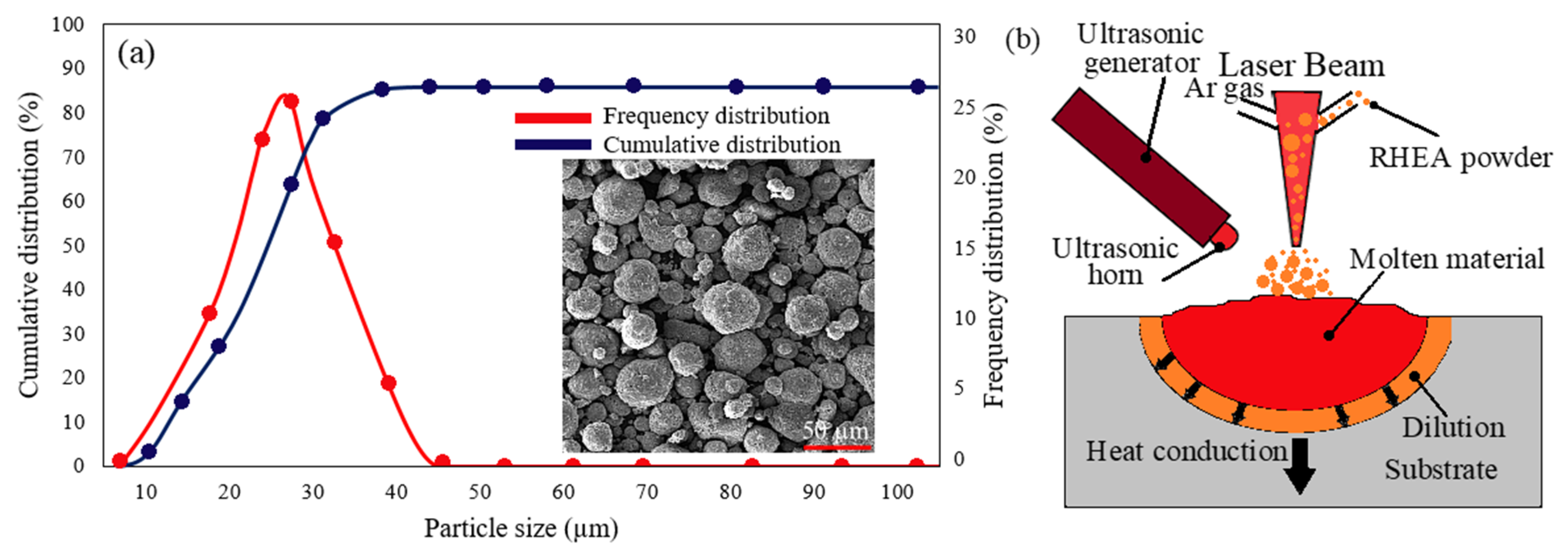
2. Materials and Methods

In this research, the GTD-111 Ni-based superalloy, which is its chemical composition listed in Table 1, is used as a substrate. The substrate was made by wire cutting from a cylindrical ingot with a length and diameter of 170 mm and 70 mm, respectively, to the dimensions of 50 × 50 × 3 mm3. High entropy NbMoTaTiNi powder with equal atomic ratio was used as RHEA coating material prepared by plasma radio frequency granulation. The molar ratio of the mixed powder also showed a near-equiatomic composition. RHEA powder had measurements of 10–40 µm and spherical morphology.
The morphology and distribution of RHEA particles are shown in Figure 1a. To coat the RHEA on the substrate, an IQL-10 pulsed Nd:YAG laser source with a maximum power of 700 W was used. An A-500 W-Lp Ophir power meter was used to measure the laser power during the operation. Ar gas was used as a carrier and protective gas at 15 l/min and 20 l/min, respectively. The distance between the nozzle and the laser and the diameter of the laser beam used was 6 mm and 1.5 mm, respectively. Simultaneously, with laser cladding, an ultrasonic source model ZJS2000J(L) and ultrasonic amplitude of 50–60 μm was used. The parameters of laser cladding and ultrasonic field are presented in Table 2. The schematic of the laser cladding process is also shown in Figure 1b.
After coating, the specimens were cross-sectioned and prepared for microstructural investigations after metallographic steps that included mounting, sanding up to #3000, polishing with Al2O3 and diamond paste, and etching. Field emission electron microscope (FESEM), Tescan model, made in the Czech country, equipped with energy-dispersive X-ray spectroscopy (EDS), electron back-scattered diffraction (EBSD), secondary electrons (SE), backscattered (BSE), and map image was used for microstructural investigations. To identify the phases, a Shimadzu XRD-6100 X-ray diffraction machine made in the Japan country at an acceleration voltage of 40 kV with a CuKα source operating at a step of 0.02° was used.
To investigate the hardness, the microhardness of the Buhler machine model made in the United States was used. For this purpose, a force of 200 g and a holding time of 15 s were used for the polished parts of the coating, HAZ, and substrate. The pin-on-disc method was used to investigate the wear behavior of the coating and the substrate. The lower counterpart was a GCr15 friction pair with a hardness of 735 HV, and the upper ones were test samples. Applied force, sliding velocity, cylindrical pin diameter, wear sliding time, and pin rotating speed used in the wear test were 60 N, 35 cm/s, 1 cm, 15 min, and 27 rpm, respectively.

3. Results

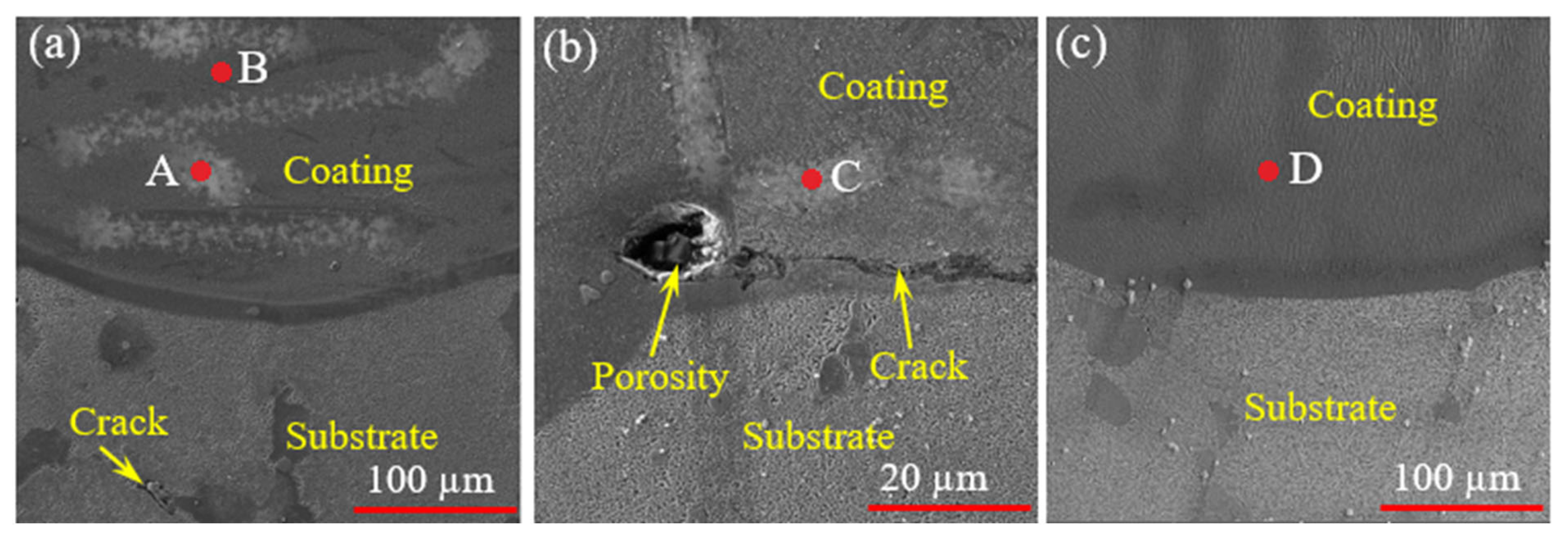
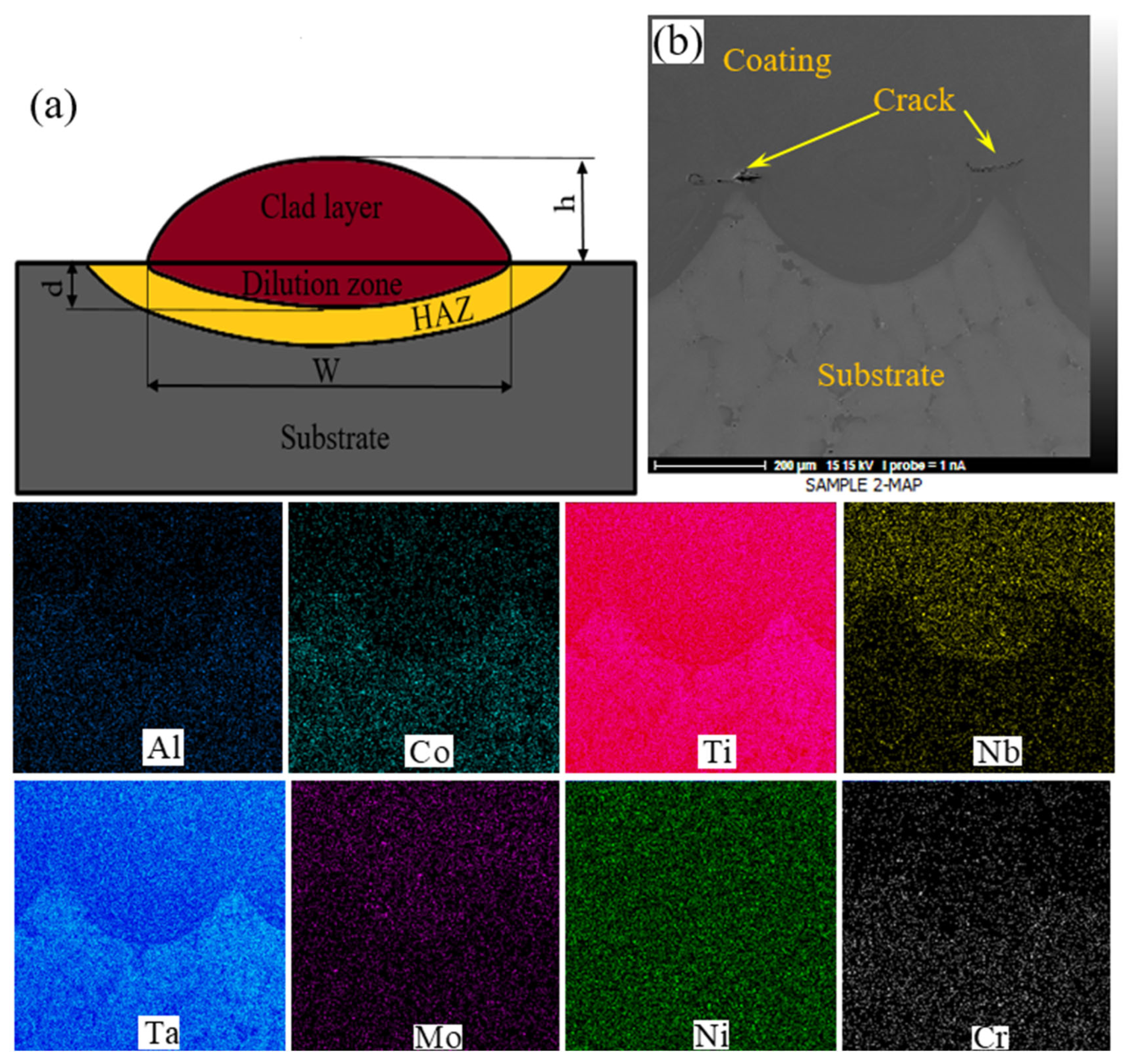
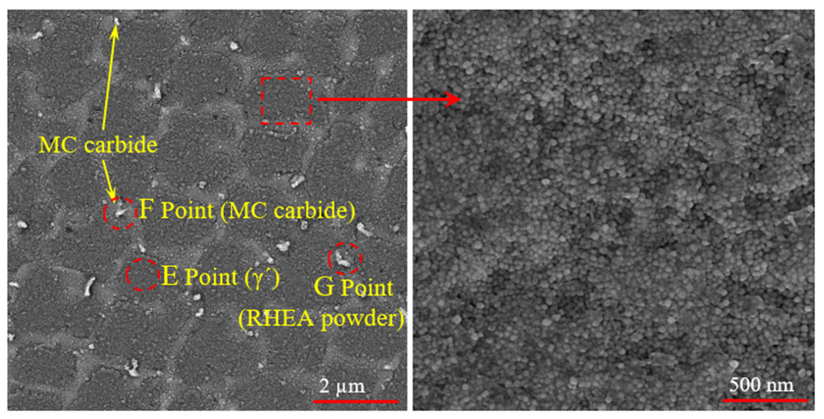
3.1. Microstructure Investigation
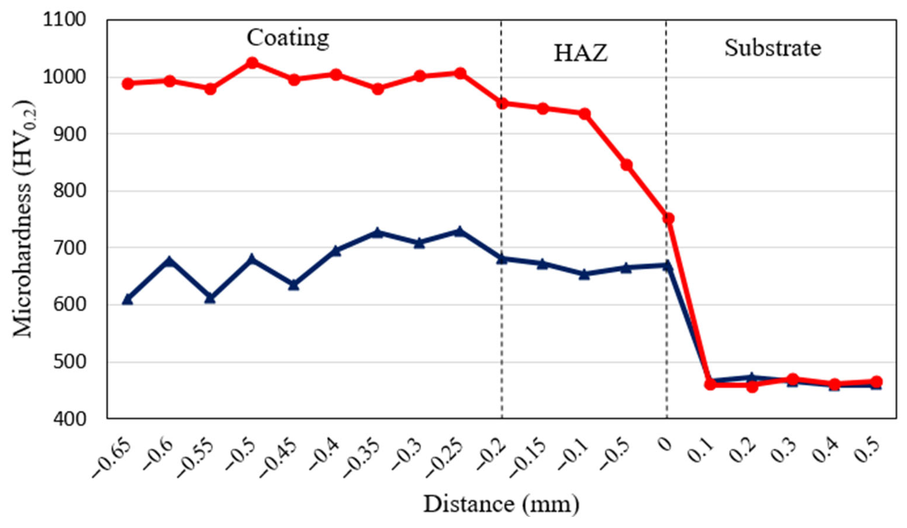
Figure 2a–c shows the coating morphology of the MT1 and MT2 specimens. As can be seen, the MT1 specimen has cracks in the interface and coating and in the HAZ. In our previous research [22], where the IN625 coating was deposited on GTD-111, it was found that the cracks and voids formed at the coating–substrate interface (as shown in Figure 2b), due to the penetration of Ti and Al, are from the bottom layer toward the coating. By increasing the solidification range (due to their low melting point compared to the coating), the above elements increase the conditions for increasing cooling stresses and shrinkage stresses. The difference in the coefficient of thermal expansion of the coating and the substrate is also another factor that causes cracks in the interface. In addition, there is some unevenness in the coating color. The results of the EDX analysis of the points marked in Figure 2 (points A to D) presented in Table 3 show that the bright areas (points A and C) are rich in coating powder elements. This shows that most of the powders in the MT1 specimen, in addition to aggregation and non-uniformity, had incomplete melting or lack of melting. This non-uniformity in the distribution of the coating powder causes a change in the molar ratio of RHEA powder. Hong et al. [23] reported that the use of unconventional heat input during laser cladding is the cause of disrupting the molar ratio of the RHEA powder and, as a result, reduces the oxidation resistance. Meanwhile, in the MT2 specimen, in addition to the appearance of no cracks, holes, or porosity in the coating, interface, and substrate, bright areas are evenly distributed in the coating, which shows that the coating powder is wholly melted during laser irradiation.
In addition to the EDX results, the XRD results in Figure 3 show that the dominant phase in the MT1 specimen is the γ phase (rich in nickel), and the dominant phase in the MT2 specimen is the NbMoTaTiNi solid solution. Therefore, it can be said that in the MT1 specimen, a high dilution was created, and the element Ni, which is the most important element of the substrate (GTD-111), penetrated the coating. According to various studies in the literature [24,25], the quality of the coating is guaranteed when the combination of the coating with the substrate (dilution) is to the extent that the metallurgical bond is established, and not more. The amount of coating dilution is calculated according to Equation (1) and Figure 4a. Based on this, the MT1 specimen with 39% dilution has more dilution than the MT2 specimen with 21% dilution. The image presented in Figure 4b (map analysis of coating) confirms this issue.
D = d i l u t i o n   z o n e   a r e a d i l u t i o n   z o n e   a r e a + c l a d   l a y e r   a r e a × 100
As stated in the literature, the melting point of the coating material and its density are significantly higher than the substrate [26]. Therefore, a high heat input is required to melt the coating material. Increasing the heat input in laser cladding prevents us from the advantage of laser cladding, which is a low heat input. A high heat input reduces the temperature gradient (G), reduces the solidification rate, increases the width of the HAZ, and also increases the dilution. In the MT1 specimen, the applied heat input is not capable of completely melting the coating powders (Figure 5). On the other side, increasing the laser power further leads to an excessive increase in the dilution and a reduction in the coating quality. The incomplete melting of the powders acts as a place of stress concentration for crack nucleation and as a place of segregation of coating elements. As seen in the map image in Figure 5, the fabric particles do not contain all the coating elements. The element Mo is enriched in the part where the powder is incompletely melted, and the elements Ti, Nb, Ni, and Ta are poor. Depleted elements participate in further solidification in three ways. First, they participate again in forming the solid solution of the NbMoTaTiNi coating, but they deviate from their stoichiometric composition. Secondly, they participate in the formation of the γ solid solution that penetrates from the substrate to the coating. Thirdly, they participate in the formation of phase and carbide precipitation such as (Ta,Ti)C and γ′ precipitations (Ni3Ti), which are rich in Ni and Ti.
Figure 6 confirms the formation of the above phases along with its EDX results in Table 3. It should be noted that the un-melted RHEA powders are the place of stress concentration due to their high brittleness. So, there are often porosity and cracks around these powders (Figure 5). In the MT2 specimen, the vibration caused by the ultrasonic field causes flow in the liquid under the right conditions, and it causes the rapid formation of micro-bubbles, which causes intense heat for the growth and unification of these bubbles, until they reach the maximum size and finally burst. The heat generated by the cavitation effect melts the powders. The vibration generated by the cavitation effect also causes the uniform distribution of melted powders throughout the coating. This was despite the fact that in the MT1 specimen, there is only the Marangoni force, which leads un-melted powders to the bottom of the liquation pool (due to the high density of the powder) and the edges of the liquation pool.
Figure 7 shows a schematic of the coating material solidification process for both the MT1 and MT2 samples. As can be seen, the substrate melts completely after laser irradiation due to its lower melting point than the coating. Powders with small particles are completely melted in both the MT1 and MT2 specimens. Powders with larger particles in the MT2 specimen have also wholly melted. However, the larger particles of the MT1 specimen are incompletely melted at the edges. During non-equilibrium laser heating, the edges of the powder react with the matrix and partially melt and decompose. These places also act as stress concentration centers during the cooling of the liquation pool, and for this reason, crack formation around these particles is observed.
In the MT1 specimen, less powders are melted. Therefore, most of the heat input by the laser is used to melt the substrate, and as shown, the dilution of the coating is increased. In such a situation, the area affected by the substrate’s heat is more expansive, and the defects caused by it also increase. In the authors’ previous research [27,28], it was mentioned that the GTD-111 nickel-based superalloy is a precipitation-hardening superalloy. The most important challenge of its welding and coating in spontaneous conditions is the formation of melting cracks in the HAZ. Figure 8 shows the heat-affected area of both the MT1 and MT2 specimens. It is noteworthy that the MT1 specimen has minor cracks around some phases. The results of the EDX analysis in Table 3 show that most of the cracks are caused by the melting of γ-γ′ eutectic, MC carbide, and γ′ phases. When the laser cladding process is performed, the rapid heating of the substrate causes a partial reaction of the edge of the phases and carbides with the alloy background (solid nickel solution). Under such conditions, localized melting occurs at these points. It should be noted that if the phase particles are small or the heating is unbalanced, they will melt completely. During the rapid cooling of the substrate, these points, because they are in a molten state, act as places of stress concentration and cause cracking in the HAZ (Figure 8a). In the conditions where the thermal stresses are lower, or the grain boundary liquation thickness is lower, the liquid zones are solidified without creating cracks (Figure 8b).
Taheri et al. [29] reported that these regions strongly reduce the creep resistance of the alloy at high temperatures. Shrinkage stresses and re-precipitation stresses are also other factors of melt cracking in the HAZ. Sometimes the amount of these stresses reaches such a level that the formation of cracks occurs in the coating area (Figure 8c). Liquation cracking was also reported in the IN738 [30], IN713 [31], and IN718 superalloys [32]. In the MT2 specimen, where most of the resulting heat is used to melt the powder, less heat reaches the substrate, which results in a decrease in the width of the HAZ and, as a result, a reduction in the susceptibility to cracking (Figure 8d). Based on the microstructural changes, the average width of the HAZ in the two samples MT1 and MT2 was measured as 380 µm and 110 µm, respectively.
Granulation, morphology, grain size, and grain aspect are among the most important factors affecting the mechanical properties of materials that are affected by solidification [33]. The SEM images in Figure 9 show that the start of solidification in specimen MT1 is columnar, and in specimen MT2, it is equiaxed. The substrate metal is the best place to start nucleation because it is cold.
The diagram in Figure 10 shows that the morphology and size of the grains depend on two factors, the solidification rate (R) and the temperature gradient (G). As can be seen, in conditions where the value of the G/R is at its lowest value, the grains are equiaxed, and with the increase in the G/R, the grains become columnar. In specimen MT1, due to more heat being applied to the substrate for melting, the value of G and R is lower than that of specimen MT2. With distance from the interface, both the G and R factors decrease further. However, since the value of the R experiences a further reduction [34], the value of the G/R decreases, and the morphology of the grains is equiaxed at the top of the coating (Figure 9). Meanwhile, the lower heat input in the MT2 specimen creates a high G value and, of course, a very high R value at the interface of the coating. Under such conditions, the value of the G/R is low from the very beginning of the growth, and the beginning of the solidification begins in the form of equiaxed grains (Figure 10). In addition to the G and R, inhomogeneous nucleation in the MT2 specimen is also the cause of the formation of equiaxed grains. The effect of cavitation, which results from strong mechanical vibration in the liquation pool, causes the solidified dendrites to be crushed and turns them into new molten nucleation centers. In addition to creating equiaxed grains, this reduces the grain aspect and grain size, as shown in Figure 11. As can be seen, by applying ultrasonic vibration to the liquation pool, the grain size decreased from 2.1 µm to 0.77 µm, and the grain aspect decreased from 4.3 to 1.8.
The EBSD image in Figure 12a,b also confirms the decrease in the grain size and aspect, as well as the changes in the grain morphology in the two specimens. In addition, it can be seen in Figure 12c,d that the amount of grains with a low-angle grain boundary (LAGB) (black lines) in the MT2 specimen significantly decreased compared to the grains with a high-angle grain boundary (HAGB) (red line) in the MT1 specimen. Taheri and Razavi [35] reported that the LAGB is the place of segregation of elements and the origin of crack nucleation in the GTD-111 composite coating reinforced with TiC particles. Among other points of the coating formed in the MT2 specimen are the zigzag grain boundaries, because zigzag grain boundaries suppress crack propagation and establish a stronger bond between the grains. At the same time, the columnar grains with smooth grain boundaries are the main centers of crack propagation and weak inter-granular bonding. Figure 12e,f shows the pole shape (PS) images containing the columnar grains (specimen MT1) during solidification. The solidification path is in the direction of the heat transfer output [36]. Meanwhile, the formation of equiaxed grains in the MT2 specimen, often caused by the crushing of grains, does not follow the solidification direction of columnar grains due to the preferential growth.
It was mentioned in the literature that the kernel average misorientation (KAM), which is derived from the EBSD results, measures the residual stress, local deformation, and stored strain energy [37]. Figure 13 shows the results of the KAM analysis of the local lattice distortion calculated by the EBSD for both specimens. As can be seen, the KAM concentration in the MT2 specimen is significantly reduced compared to the MT1 specimen. The heterogeneous distribution of the microstructure in the MT1 specimen is the most important factor in increasing its stress. This stress is usually caused by the stress of cooling, precipitation, and the stress caused by the difference in the thermal expansion coefficient between the coating and the substrate. It can be seen that the homogeneous microstructure in the MT2 specimen reduced the stress concentration in the coating. This factor is attributed to the mechanical vibration caused by the ultrasound. Therefore, the reduction in the stress value in the MT2 specimen compared to the MT1 specimen is one of the other factors affecting crack reduction.

3.2. Hardness

Figure 14 shows the hardness results of the MT1 and MT2 specimens. As can be seen, the coating hardness of both specimens is significantly higher than the substrate. This is attributed to the high inherent hardness of the coating particles and the grain refinement process in the coating, which is one of the characteristics of laser cladding [38]. As expected, the average hardness number in the MT2 specimen is about 42% higher than that of the MT1 specimen. One of the reasons for this is the smaller average grain size and the number of smaller grains in the MT2 specimen compared to the MT1 specimen (see Figure 11). Another effective factor in the hardness of the MT2 specimen is the uniform distribution of the microstructure. As can be seen in Figure 14, specimen MT2 experiences less hardness fluctuation than specimen MT1, which is attributed to the uniform distribution of the structure. The uniform distribution of the microstructure in MT2 is also attributed to the effect of cavitation and the creation of impact forces caused by the bursting of bubbles in the entire coating. Meanwhile, in the MT1 specimen, the Marangoni force in the coating led the coating material to its lower part, resulting in uneven hardness distribution. As shown in Figure 13, the residual stress in the MT1 specimen was higher than in the MT2 specimen. This helps to increase the hardness of the MT1 specimen. However, the hardness results in Figure 14 shows that the facts of smaller grain size, the number of smaller grains, and the uniform distribution of the microstructure have a more effective impact on increasing the hardness of the microstructure. This is confirmed in the study of Taheri et al. [38].

3.3. Wear

Figure 15 shows the wear test results of the substrate and the MT1 and MT2 specimens, which include the coefficient of friction (COF), wear rate, and wear volume lost. It is clear that the substrate, with an average COF of 1.12, has a higher COF than the MT1 and MT2 specimens with the COF of 0.62 and 0.42, respectively (Figure 15a). In confirmation of the COF results, the results of the wear volume loss and the wear rate in Figure 15b for the substrate, MT1 and MT2 specimens are from the highest to the lowest. So, the amount of wear volume loss for the substrate, specimen MT1, and specimen MT2 was 0.147, 0.092, and 0.038 × 105µm3, respectively, and the wear rate for the substrate, specimen MT1, and specimen MT2 was 0.91 × 10⁻⁶, 0.54 × 10⁻⁶, and 0.32 × 10⁻⁶ mm3/Nm, respectively. These results are in agreement with the hardness test results. It is stated in the literature that with the increase in the hardness, the wear resistance increases [39]. The weaker wear behavior of the substrate compared to the coating was not unexpected. The better wear behavior of the MT2 specimen compared to the MT1 specimen, as studied in the previous sections, is attributed to the fineness of the grain, the grain aspect, the uniform distribution of the microstructure, and the absence of cracks, all of which are caused by the cavitation effect of the ultrasonic field. In addition, it is stated in the literature that the wear rate is also dependent on the relationship between the hardness (H) and elastic modulus (E) [40,41,42]. So, the wear resistance increases with the increase in the H/E. The value of E for each of the substrate samples, MT1 and MT2, is obtained according to Equation (2) as follows:
E = stress (σ)/strain (ε)
The stress and strain values were obtained through small punch test (punch diameter: 3 mm) [43]. For this purpose, specimens with a diameter of 10 mm and a thickness of 0.5 mm were separated from the coating part via wire cutting and subjected to small punch test. Figure 15c shows the values of H and H/E for the substrate and specimens MT1 and MT2. The MT2 specimen with the highest H/E has the highest wear resistance (see Figure 15a). High H/E delays the entry time of the wear force from the elastic region to the plastic. While the substrate with the lowest H/E has a shorter time to enter from elastic to plastic, the highest force is applied in the plastic area. Figure 15d also confirms that the wear depth decreases with the increased H/E. The MT2 specimen with the H/E of 4.08 entered the plastic wear with a longer delay, and, as a result, had a lower wear depth (1.6 µm). On the contrary, the substrate with the H/E of 1.79 passed the transition stage from elastic to plastic sooner and underwent more profound deformation (4 µm).
The SEM images of the worn surface in Figure 16 after the wear test show that the MT2 specimen and the substrate have the least and the most scratches (plastic deformation), respectively. A refined microstructure, without cracks and a high amount of H/E in the MT2 specimen, is the most important reason for the formation of shallow and partial scratches on the worn surface. In a study, Paidar et al. [44] reported the formation of equiaxed grains in the coating as the cause of the increased wear resistance due to stronger atomic bonding. Similar results were also reported by Wang et al. [45]. In this study, the MT2 specimen with zigzag grain boundaries (see Figure 12) has stronger atomic bonds, and as a result, it undergoes plastic deformation later. The substrate formed a tribofilm due to its lower hardness. The MT1 specimen also suffered shallower scratches than the substrate and more profound scratches than the MT2 specimen. Deep scratches lead to more wear volume loss (see Figure 15b) and, as a result, create more worn debris during wear.

4. Conclusions

In this work, the effect of the ultrasonic field on the microstructure and mechanical properties of the NbMoTaTiNi refractory coating applied using the laser cladding method was investigated, and the following results were obtained:
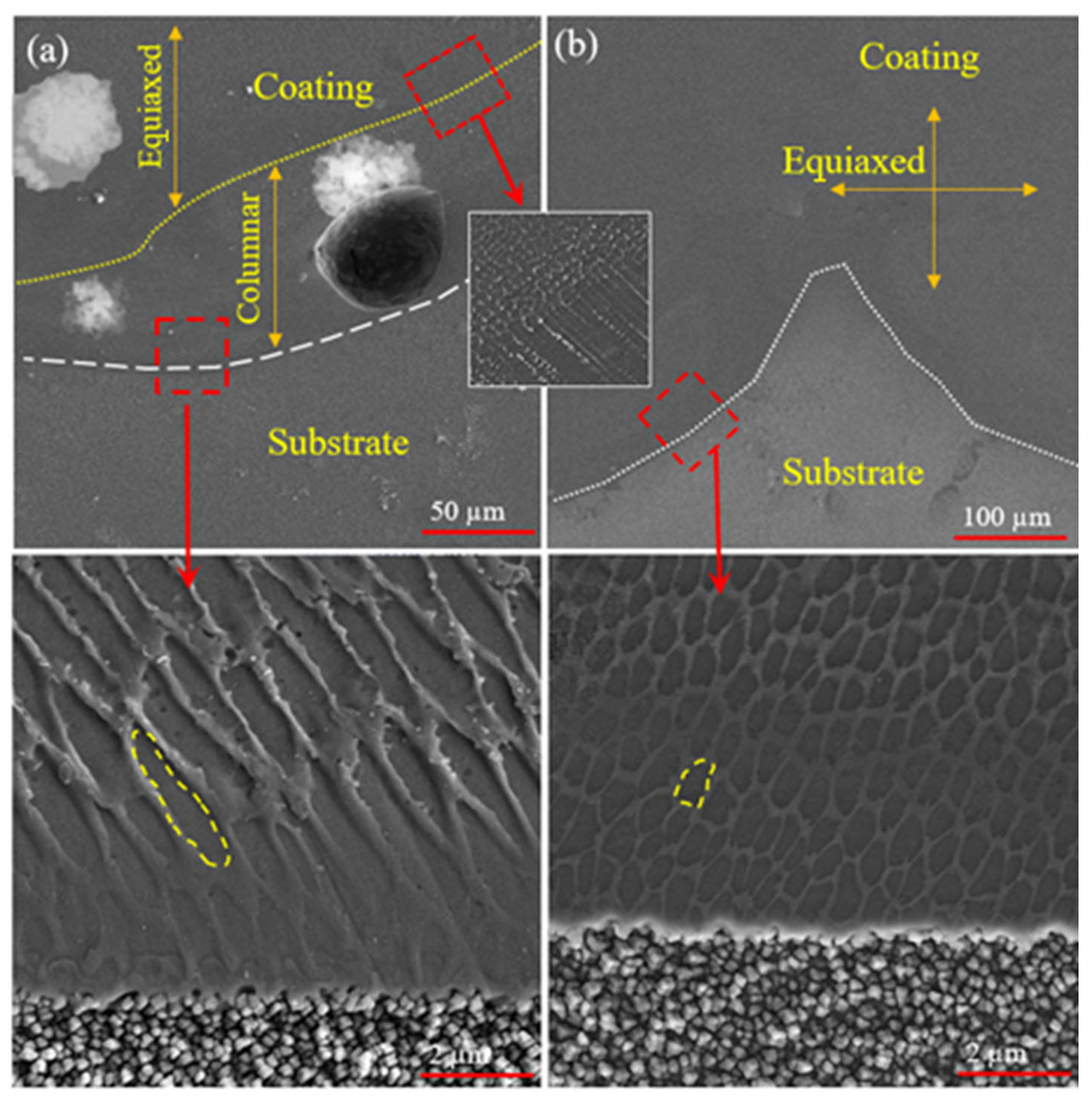
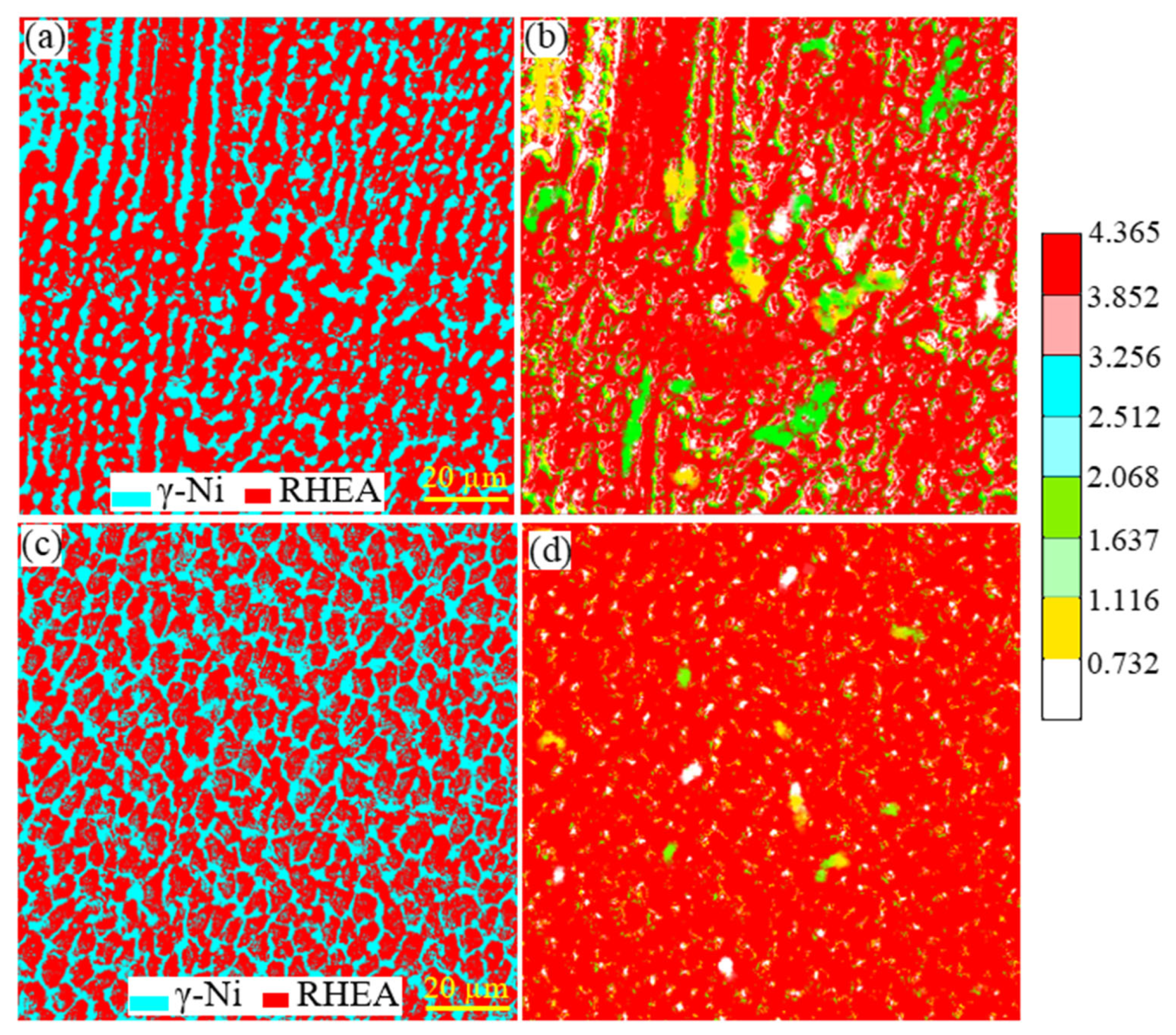
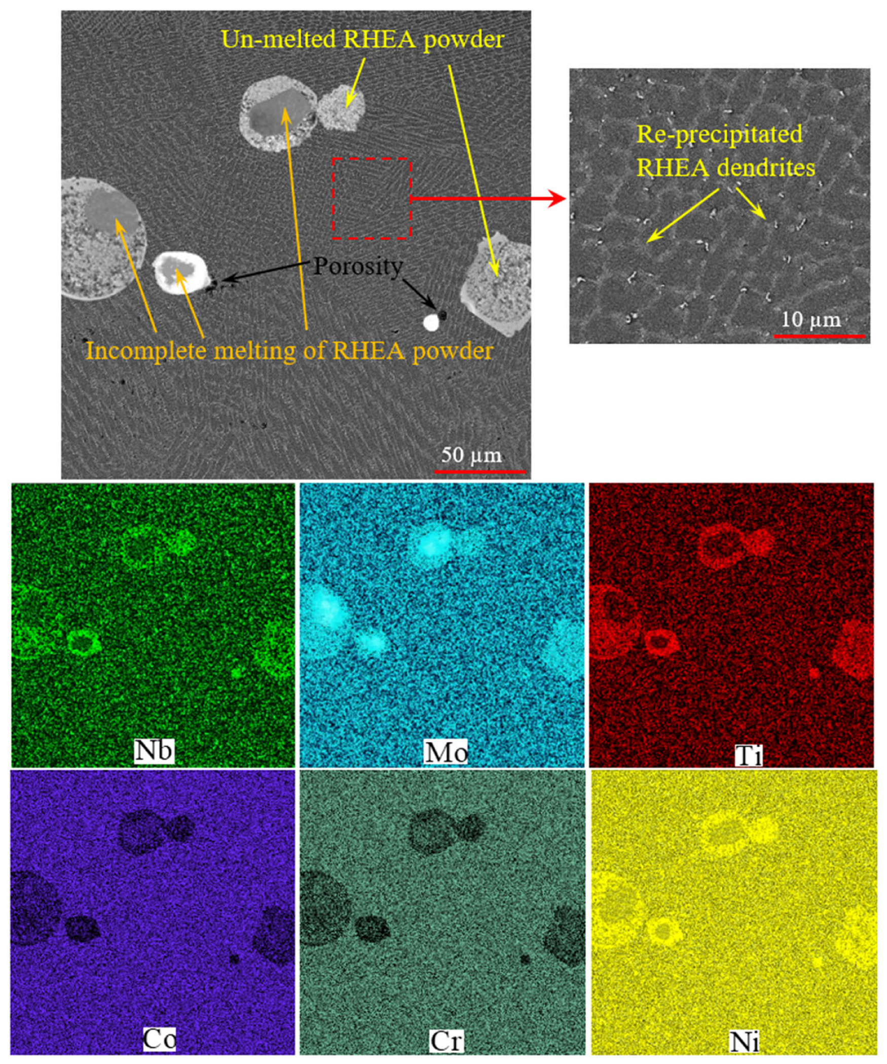
  • Application of ultrasonic field during laser cladding resulted in the uniform two-phase coating. This was attributed to the cavitation effect.
  • Applying the ultrasonic field increased the temperature of the coating and led to the complete melting of the powders due to vibration. As a result, the dilution was reduced without increasing the laser power to melt the coating.
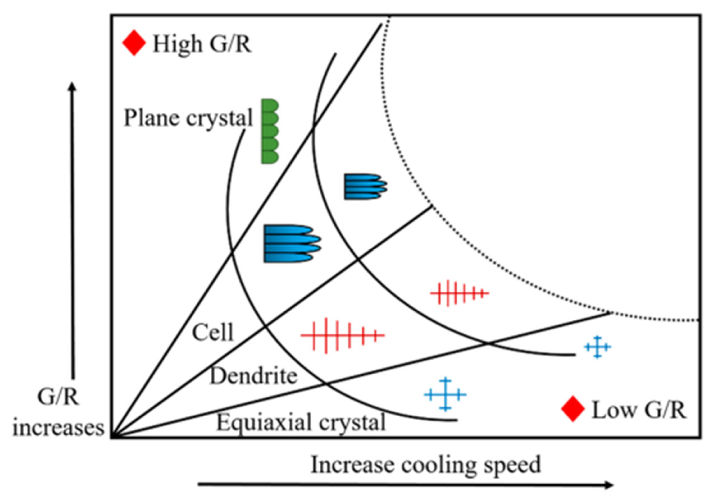
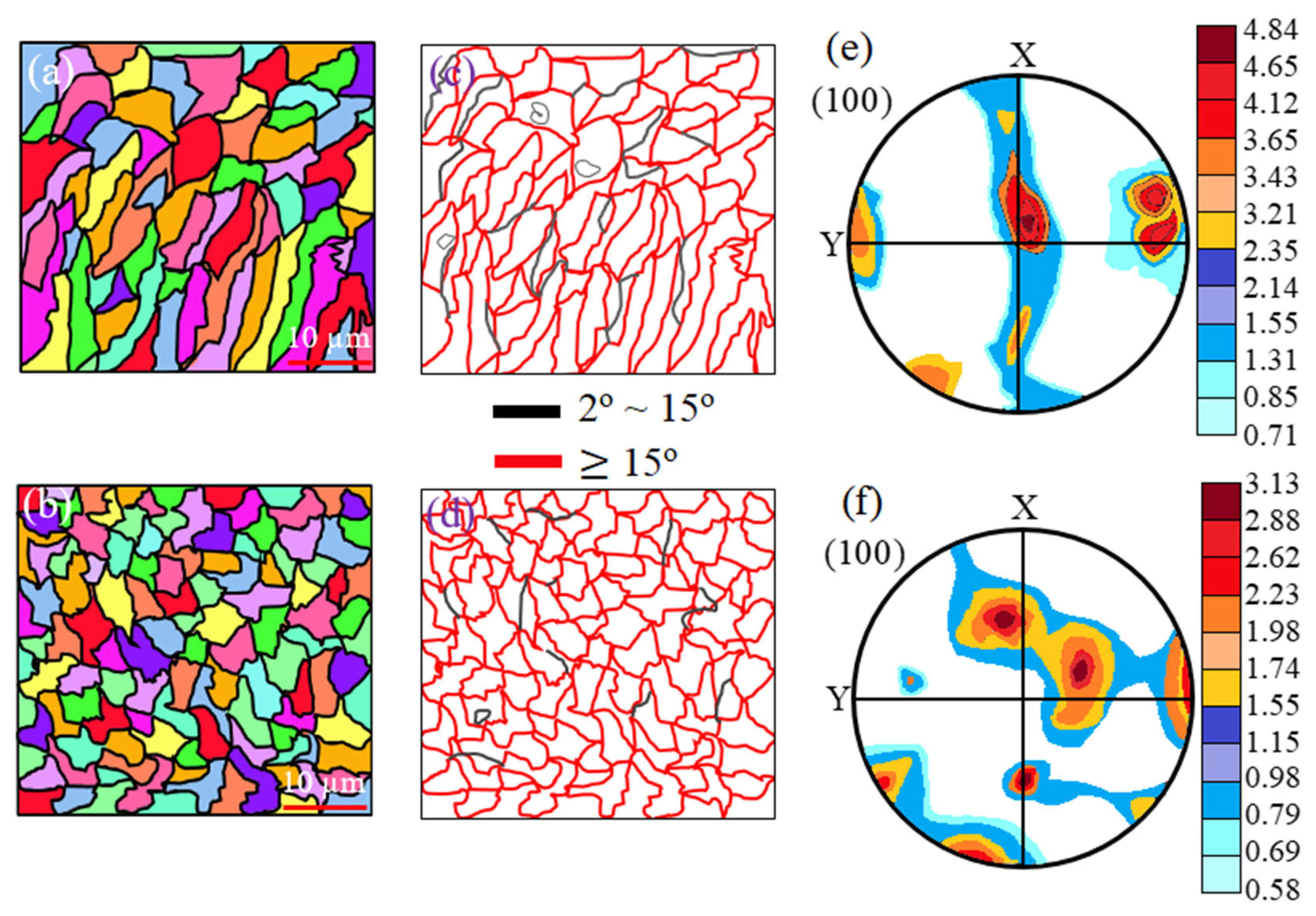
  • The mechanical vibration caused by the ultrasonic field crushes the growing RHEA dendrites. Under such conditions, in addition to the formation of equiaxed grains, the creation of non-solidification nucleation centers is encouraged for the formation of more equiaxed grains. So, by applying the ultrasonic field, the grain size decreased from 2.1 to 0.77 µm, and the grain aspect decreased from 4.3 to 1.8.
  • The ultrasonic field caused the formation of equiaxed grains with strong bonding and zigzag grain boundaries. This caused a decrease in the COF from 0.62 to 0.42, a reduction in the wear volume from 0.092 to 0.038×105 µm3, and a reduction in the wear rate from 0.54 × 10⁻⁶ to 0.32 × 10⁻⁶ mm3/Nm.

Author Contributions

Conceptualization, S.Z., M.T. and K.S.; methodology, S.Z. and W.S.; validation, M.T., M.N. and K.S.; formal analysis, S.Z. and K.B.; investigation, M.P. and W.S.; writing—original draft preparation, M.T.; writing—review and editing, S.Z., M.N., K.B., M.P. and W.S.; visualization, M.N. and M.T.; supervision, M.T. and K.S.; project administration, M.T.; resources, S.Z. and M.T. All authors have read and agreed to the published version of the manuscript.

Funding

This research received no external funding.

Institutional Review Board Statement

Not applicable.

Informed Consent Statement

Not applicable.

Data Availability Statement

Not applicable.

Acknowledgments

The authors extend their appreciation to the Iranian Research Organization for Science and Technology (IROST) for funding this research work through the project number 1012095010.

Conflicts of Interest

The authors declare no conflict of interest.

References

  1. Wei, Z.; Taheri, M.; Li, C.; Mehrez, S. The effect of laser pressure welding parameters on GTD-111 superalloy microstructure. Mater. Lett. 2022, 316, 132020. [Google Scholar] [CrossRef]
  2. Barwinska, I.; Kopec, M.; Kukla, D.; Senderowski, C.; Kowalewski, Z.L. Thermal Barrier Coatings for High-Temperature Performance of Nickel-Based Superalloys: A Synthetic Review. Coatings 2023, 13, 769. [Google Scholar] [CrossRef]
  3. Taheri, M.; Rasoulpouraghdam, A.; Lohrasbi-Nejad, A.; Kashani-Bozorg, S.F.; Liavoli, R.P. Influence of heat treatment on creep behavior of IN625 coating on a Ni3Al-base superalloy. Mater. Res. Express 2021, 8, 056503. [Google Scholar] [CrossRef]
  4. Taheri, M.; Kashani-Bozorg, S.F.; Alizadeh, A.; Beni, M.H.; Jam, J.E.; Khorram, A. Analysis of liquation and solidification cracks in the electron beam welding of GTD-111 nickel-base superalloy joint. Mater. Res. Express 2021, 8, 076507. [Google Scholar] [CrossRef]
  5. Lont, A.; Poloczek, T.; Górka, J. The structure and properties of laser-cladded Inconel 625/TiC composite coatings. Mater. Sci. Pol. 2022, 40, 91–103. [Google Scholar] [CrossRef]
  6. Taheri, M.; Salemi Golezani, A.; Shirvani, K. Effect of Aluminide coating on rapture behavior of Ni-based superalloy GTD-111 in high temperature. In Advanced Materials Research; Trans Tech Publications Ltd.: Baech, Switzerland, 2012; Volume 457, pp. 330–333. [Google Scholar]
  7. Khorram, A.; Taheri, M. Surface modification of IN713 LC superalloy with Metco 204NS by laser surface alloying. Laser Phys. 2022, 32, 106001. [Google Scholar] [CrossRef]
  8. Rezayat, M.; Sani, A.A.; Noghani, M.T.; Yazdi, M.S.; Taheri, M.; Moghanian, A.; Mohammadi, M.A.; Moradi, M.; García, A.M.M.; Besharatloo, H. Effect of Lateral Laser-Cladding Process on the Corrosion Performance of Inconel 625. Metals 2023, 13, 367. [Google Scholar] [CrossRef]
  9. Senkov, O.N.; Miracle, D.B.; Chaput, K.J.; Couzinie, J.P. Development and exploration of refractory high entropy alloys—A review. J. Mater. Res. 2018, 33, 3092–3128. [Google Scholar] [CrossRef]
  10. Zhuang, D.D.; Du, B.; Zhang, S.H.; Tao, W.W.; Wang, Q.; Shen, H.B. Effect and action mechanism of ultrasonic assistance on microstructure and mechanical performance of laser cladding 316L stainless steel coating. Surf. Coat. Technol. 2022, 433, 128122. [Google Scholar] [CrossRef]
  11. Wen, X.; Cui, X.; Jin, G.; Zhang, X.; Zhang, Y.; Zhang, D.; Fang, Y. Design and characterization of FeCrCoAlMn0. 5Mo0. 1 high-entropy alloy coating by ultrasonic assisted laser cladding. J. Alloys Compd. 2020, 835, 155449. [Google Scholar] [CrossRef]
  12. Taheri, M.; Razavi, M.; Kashani-Bozorg, S.F.; Torkamany, M.J. Relationship between solidification and liquation cracks in the joining of GTD-111 nickel-based superalloy by Nd: YAG pulsed-laser welding. J. Mater. Res. Technol. 2021, 15, 5635–5649. [Google Scholar] [CrossRef]
  13. Wang, H.; Cheng, Y.; Geng, R.; Wang, B.; Chen, Y.; Liang, X. Comparative study on microstructure and properties of Fe-based amorphous coatings prepared by conventional and high-speed laser cladding. J. Alloys Compd. 2023, 952, 169842. [Google Scholar] [CrossRef]
  14. Yang, T.; Wu, W.; Lei, Y.; Chen, P.; Liu, H.; Zhao, L.; Qiu, C. Effect of Co/TiAl on Mechanical Properties of Laser Melted IN 625 on 304SS Matrix. Coatings 2023, 13, 768. [Google Scholar] [CrossRef]
  15. Hao, X.; Liu, H.; Zhang, X.; Tao, J.; Wang, Y.; Yang, C.; Liu, Y. Microstructure and wear resistance of in-situ TiN/(Nb, Ti) 5Si3 reinforced MoNbTaWTi-based refractory high entropy alloy composite coatings by laser cladding. Appl. Surf. Sci. 2023, 626, 157240. [Google Scholar] [CrossRef]
  16. Gao, Q.; Liu, H.; Chen, P.; Liu, X.; Yang, H.; Hao, J. Multi-objective optimization for laser cladding refractory MoNbTiZr high-entropy alloy coating on Ti6Al4V. Opt. Laser Technol. 2023, 161, 109220. [Google Scholar] [CrossRef]
  17. Lou, L.Y.; Liu, K.C.; Jia, Y.J.; Ji, G.; Wang, W.; Li, C.J.; Li, C.X. Microstructure and properties of lightweight Al0. 2CrNbTiV refractory high entropy alloy coating with different dilutions deposited by high speed laser cladding. Surf. Coat. Technol. 2022, 447, 128873. [Google Scholar] [CrossRef]
  18. Taheri, M.; Halvaee, A.; Kashani-Bozorg, S.F. Effect of Nd:YAG pulsed-laser welding parameters on microstructure and mechanical properties of GTD-111 superalloy joint. Mater. Res. Express 2019, 6, 076549. [Google Scholar] [CrossRef]
  19. Zhao, S.; Zhang, B.; Mehrez, S.; Vignesh, R.V.; Taheri, M.; Sharifi, T. Laser cladding of IN625 superalloy assisted by hybrid ultrasonic-electromagnetic field. Mater. Lett. 2022, 323, 132592. [Google Scholar] [CrossRef]
  20. Song, H.; Jiang, F.; Guo, C.; Sun, Q.; Li, H.; Yang, Z.; Li, L.; Diao, M.; Zhang, Z. Effect of ultrasonic vibration on the microstructure and microhardness of laser cladding Fe-based crystalline/amorphous composite coatings. Mater. Lett. 2023, 335, 133780. [Google Scholar] [CrossRef]
  21. Wang, J.; Zhou, J.; Zhang, T.; Meng, X.; Li, P.; Huang, S.; Zhu, H. Ultrasonic-Induced Grain Refinement in Laser Cladding Nickel-Based Superalloy Reinforced by WC Particles. Coatings 2023, 13, 151. [Google Scholar] [CrossRef]
  22. Cao, Y.; Farouk, N.; Taheri, M.; Yumashev, A.V.; Bozorg, S.F.K.; Ojo, O.O. Evolution of solidification and microstructure in laser-clad IN625 superalloy powder on GTD-111 superalloy. Surf. Coat. Technol. 2021, 412, 127010. [Google Scholar] [CrossRef]
  23. Hong, S.; Li, J.; Zhao, P.; Xu, Y.; Li, W. Evolution in Wear and High-Temperature Oxidation Resistance of Laser-Clad AlxMoNbTa Refractory High-Entropy Alloys Coatings with Al Addition Content. Coatings 2022, 12, 121. [Google Scholar] [CrossRef]
  24. Zhu, L.; Yang, Z.; Xin, B.; Wang, S.; Meng, G.; Ning, J.; Xue, P. Microstructure and mechanical properties of parts formed by ultrasonic vibration-assisted laser cladding of Inconel 718. Surf. Coat. Technol. 2021, 410, 126964. [Google Scholar] [CrossRef]
  25. Zhang, G.; Xiao, C.; Taheri, M. Effect of Nd:YAG pulsed laser welding process on the liquation and strain-age cracking in GTD-111 superalloy. J. Manuf. Process. 2020, 52, 66–78. [Google Scholar] [CrossRef]
  26. Taheri, M.; Kashani-Bozorg, S.F.; Ramalingam, V.V.; Babaei, B.; Halvaee, A. Effect of Nd:YAG Pulsed-Laser Welding Parameters on Melting Rate of GTD-111 Superalloy Joint. J. Mater. Eng. Perform. 2021, 30, 9108–9117. [Google Scholar] [CrossRef]
  27. Taheri, M.; Halvaee, A.; Kashani-Bozorg, S.F. Hot Cracking of GTD-111 Nickel-Based Superalloy Welded by Pulsed Nd:YAG Laser. Met. Microstruct. Anal. 2020, 9, 16–32. [Google Scholar] [CrossRef]
  28. Wang, F.; Taheri, M. Determination of Ideal Conditions for GTD-111 Superalloy Welding Through Pre-Heating, Pre-Cold and Heat Treatment. Met. Mater. Int. 2020, 27, 3462–3477. [Google Scholar] [CrossRef]
  29. Taheri, M. Development of a novel method for measuring the interfacial creep strength of laser cladding coatings. Results Opt. 2022, 7, 100226. [Google Scholar] [CrossRef]
  30. Taheri, M. Analysis of Solidification and Liquation Cracks in the Electron Beam Welding of IN738 Superalloy. Met. Microstruct. Anal. 2021, 10, 815–822. [Google Scholar] [CrossRef]
  31. Liang, T.; Wang, L.; Liu, Y.; Song, X. Microstructure and Mechanical Properties of Laser Welded Joints of DZ125L and IN718 Nickel Base Superalloys. Met. Mater. Int. 2018, 24, 604–615. [Google Scholar] [CrossRef]
  32. Xiao, B.; Liu, H.; Jia, W.; Wang, J.; Zhou, L. Cracking suppression in selective electron beam melted WMoTaNbC refractory high-entropy alloy. J. Alloys Compd. 2023, 948, 169787. [Google Scholar] [CrossRef]
  33. Stanciu, E.M.; Pascu, A.; Croitoru, C.; Roată, I.C.; Cristea, D.; Tierean, M.H.; Hulka, I.; Petre, I.M.; Rosca, J.C.M. Functional Surfaces via Laser Processing in Nickel Acetate Solution. Materials 2023, 16, 3087. [Google Scholar] [CrossRef] [PubMed]
  34. Park, J.; Lee, S.H. CMT-Based Wire Arc Additive Manufacturing Using 316L Stainless Steel (2): Solidification Map of the Multilayer Deposit. Metals 2021, 11, 1725. [Google Scholar] [CrossRef]
  35. Taheri, M.; Razavi, M. Effect of TiC on the microstructure of GTD-111 superalloy processed by laser powder bed fusion. Mater. Lett. 2022, 328, 133091. [Google Scholar] [CrossRef]
  36. Zhou, J.-L.; Cheng, Y.-H.; Chen, Y.-X.; Liang, X.-B. Composition design and preparation process of refractory high-entropy alloys: A review. Int. J. Refract. Met. Hard Mater. 2022, 105, 105836. [Google Scholar] [CrossRef]
  37. Wang, H.; Zhai, Y.; Zhou, L.; Zhang, Z. Study on Laser Surface Hardening Behavior of 42CrMo Press Brake Die. Coatings 2021, 11, 997. [Google Scholar] [CrossRef]
  38. Taheri, M.; Vashian, S.; Zamani, N.; Torkamany, P.; Heidarpour, I.; Torkamany, M.J. Measurement of local creep life of laser cladding coatings by small punch creep test. Eng. Fail. Anal. 2022, 139, 106524. [Google Scholar] [CrossRef]
  39. Benincá, F.P.; Romero, M.C.; Camporez, R.M.; Neto, C.A.R.; Strey, N.F.; Scandian, C. Evolution of morphology, microstructure and hardness of bodies and debris during sliding wear of carbon steels in a closed tribosystem. Wear 2023, 523, 204809. [Google Scholar] [CrossRef]
  40. Zuo, Z.; Taheri, M.; Razavi, M.; Torkamany, M.J.; Rasoulpouraghdam, A.; Vignesh, R.V. Effect of magnetic field on tribological properties of IN718 superalloy coating produced by laser cladding on GTD-111 superalloy. Vacuum 2022, 203, 111311. [Google Scholar] [CrossRef]
  41. Leyland, A.; Matthews, A. On the significance of the H/E ratio in wear control: A nanocomposite coating approach to optimised tribological behaviour. Wear 2000, 246, 1–11. [Google Scholar] [CrossRef]
  42. Beake, B.D. The influence of the H/E ratio on wear resistance of coating systems—Insights from small-scale testing. Surf. Coat. Technol. 2022, 442, 128272. [Google Scholar] [CrossRef]
  43. Yang, S.-S.; Ling, X.; Du, P. Elastic and plastic deformation behavior analysis in small punch test for mechanical properties evaluation. J. Cent. South Univ. 2018, 25, 747–753. [Google Scholar] [CrossRef]
  44. Paidar, M.; Bokov, D.; Mehrez, S.; Ojo, O.O.; Ramalingam, V.V.; Memon, S. Improvement of mechanical and wear behavior by the development of a new tool for the friction stir processing of Mg/B4C composite. Surf. Coat. Technol. 2021, 426, 127797. [Google Scholar] [CrossRef]
  45. Zhang, B.; Shirvani, K.; Taheri, M.; Beirami, K.; Wang, Y. Effect of TiC and Magnetic Field on Microstructure and Mechanical Properties of IN738 Superalloy Processed by Selective Laser Melting. J. Mater. Eng. Perform. 2023, 1–16. [Google Scholar] [CrossRef]
Figure 1. (a) SEM morphology and particle size distribution of RHEA powder; (b) schematic of laser cladding process equipped with ultrasonic.
Coatings 13 00995 g001
Figure 2. FESEM image of the coating cross-section (a) and (b) sample MT1, (c) sample MT2.
Coatings 13 00995 g002
Figure 3. The XRD results of MT1 and MT2 specimens.
Coatings 13 00995 g003
Figure 4. (a) Schematic of coating dilution; (b) map image of the coating of MT1 sample showing the diffusion of different elements and the dilution of the coating.
Coatings 13 00995 g004
Figure 5. Map analysis of un-melted RHEA powder sample MT1 during laser cladding.
Coatings 13 00995 g005
Figure 6. Precipitation of γ′ nanoparticles (point E), MC carbide (point F), and fine particles remaining from un-melted RHEA powder (point G) in sample MT1.
Coatings 13 00995 g006
Figure 7. Schematic of solidification process of MT1 and MT2 samples.
Coatings 13 00995 g007
Figure 8. (a) Liquation crack formation in the HAZ of sample MT1. (b) Formation of grain boundary liquation in the HAZ of sample MT1. (c) Cracking caused by thermal stresses at the beginning of the coating. (d) No defect formation in the HAZ of sample MT2.
Coatings 13 00995 g008
Figure 9. (a) Columnar growth of grains in MT1 sample coating and (b) equiaxed growth of grains in MT2 sample coating.
Coatings 13 00995 g009
Figure 10. Temperature gradient–growth rate diagram to determine the morphology of grains.
Coatings 13 00995 g010
Figure 11. The EBSD statistics of grain size in (a) MT1 and (b) MT2 specimens.
Coatings 13 00995 g011
Figure 12. (a) EBSD analysis of MT1 and (b) MT2 specimen, (c) corresponding grain boundary misorientation distribution figures of MT1 and (d) MT2 specimen, and (e) pole figures illustrating the texture analysis of the MT1 and (f) MT2 specimen.
Coatings 13 00995 g012
Figure 13. EBSD results of the phase distribution, KAM maps, (a,b) MT1 specimen, and (c,d) MT2 specimen.
Coatings 13 00995 g013
Figure 14. The micro-hardness profile of MT1 and MT2 samples.
Coatings 13 00995 g014
Figure 15. Tribological behavior of coating and substrate. (a) COF, (b) wear rate and wear volume loss, (c) elastic modulus, and (d) the cross-section profile of the wear scar.
Coatings 13 00995 g015
Figure 16. Worn surfaces of the sample (a) substrate, (b) MT1, and (c) MT2.
Coatings 13 00995 g016
Table 1. Chemical composition of as-cast GTD-111 superalloy (wt%).
CrCoTiAlTaWMoNbBZrCNi
149.64.93.12.83.81.50.070.0140.030.1Bal
Table 2. Laser cladding and ultrasonic parameters.
Sample No.Average Power (W)Scan Velocity (mm/s)Powder Feed Rate (mg/s)Hatch Distance (µm)Laser Beam Focus (µm)Vibration Frequency (KHz)Ultrasonic Generator (µm)Vibration Amplitude (µm)Ultrasonic Power (W)
MT1200630080100----
MT220063008010025250.5250
Table 3. The results of EDX analysis of the determined points in Figure 2, Figure 6, and Figure 8.
PointNbMoTaTiNiAlCoCr
A19.814.212.912.836.31.31.41.3
B11.211.814.410.740.73.53.14.6
C17.213.214.513.739.10.80.41.1
D18.215.719.617.723.81.51.61.9
E-11.5-1659.592.61.4
F4.95.72656.94.2-1.31
G25.711.823.627.811.1---
H-17.5-2.873.26.5--
I-1.216.567-4.991.4
J-136.557--32.5
Disclaimer/Publisher’s Note: The statements, opinions and data contained in all publications are solely those of the individual author(s) and contributor(s) and not of MDPI and/or the editor(s). MDPI and/or the editor(s) disclaim responsibility for any injury to people or property resulting from any ideas, methods, instructions or products referred to in the content.

