Article

Corrosion Resistance, Interfacial Contact Resistance, and Hydrophobicity of 316L Stainless Steel Bipolar Plates Coated with TiN/Amorphous Carbon Double Layer under Different Carbon Target Currents

School of Materials Science and Engineering, Shanghai University, Shanghai 200444, China
Coatings 2023, 13(9), 1494; https://doi.org/10.3390/coatings13091494
Submission received: 24 July 2023 / Revised: 13 August 2023 / Accepted: 21 August 2023 / Published: 24 August 2023

Abstract

:
To improve the corrosion, interfacial contact resistance, and hydrophobicity of bipolar plates used in proton-exchange membrane fuel cells, a series of TiN/amorphous carbon double-layer coatings was prepared on 316L stainless steel using magnetron sputtering. The structure of the amorphous carbon was controlled with different carbon target currents. The changed rules in the coating structure and performance under different carbon target currents were studied. Due to appropriate sputtering energy, an appropriate carbon target current reduced the grain boundary of the coating, resulting in a smoother surface, and increased the content of sp2 hybrid carbon. Compared with uncoated 316L stainless steel, the samples coated with amorphous carbon showed greatly improved corrosion resistance and conductivity. At a carbon target current of 5 A, low contact resistance and high corrosion resistance were achieved simultaneously. The significant improvement in corrosion resistance is attributed to the improvement in the quality of the coating surface. Due to the appropriate carbon target current increasing the content of sp2 hybrid carbon in the coating, the contact resistance of the coating was reduced. When the carbon target current was 5 A, the interfacial contact resistance of the sample was 3.9 mΩ·cm2, which is significantly lower than that of bare 316L stainless steel. After constant potential polarization testing, the coating still exhibited good conductivity.

1. Introduction

Environmental pollution is increasingly intensifying at present, and the development and utilization of new energy sources, such as hydrogen energy, are vital to addressing the future energy crisis. Proton-exchange membrane fuel cells (PEMFCs) are a new type of hydrogen energy utilization device that can meet various usage requirements for automobiles, electronic devices, etc. [1,2,3]. Bipolar plates are an essential component of proton-exchange membrane fuel cells, accounting for 70%–80% of the total weight of the fuel cell and 25%–40% of the cost [4,5,6]. Bipolar plates can transmit gas through flow channels and collect and conduct current and support the membrane electrode, undertaking the fuel cell’s heat dissipation and drainage functions [7].
Bipolar plates need low interfacial contact resistance and high corrosion resistance to meet the needs of the high-acid environment inside a fuel cell. They also require a certain degree of hydrophobicity to prevent flooding inside the cell stack. For this, the U.S. Department of Energy has put forward requirements for the corrosion resistance and conductivity of bipolar plates: the corrosion current density should be <1 μm/cm2, and the interfacial contact resistance should be <10 mΩ·cm2 [8] (DOE 2020 target). Graphite is an excellent bipolar plate material. This material has good conductivity and corrosion resistance, but graphite bipolar plates are expensive. Moreover, their processing performance and mechanical properties are poor. Developing new bipolar plate materials to replace graphite is the current development direction of fuel cell bipolar plates [5,9].
Metal bipolar plates are inexpensive and own excellent physical properties. Hence, they have been widely developed by researchers, such as aluminum, stainless steel, titanium, nickel, magnesium, etc. [10,11,12,13]. Stainless steel is an ideal bipolar plate material because it is widely used, inexpensive, easy to process, and has excellent electrical conductivity [14]. However, stainless steel is prone to corrosion in the acidic environment of PEMFCs, and due to passivation, an oxide layer forms on the surface of stainless steel. This oxide layer has semiconductor properties and poor conductivity, significantly increasing stainless steel’s interfacial contact resistance (ICR) [15]. The key to solving these problems is to prepare a suitable conductive and corrosion-resistant coating on the surface of the stainless steel to improve its corrosion resistance and reduce its interfacial contact resistance [16]. Researchers often use electroplating, chemical vapor deposition, and physical vapor deposition to prepare nitrides, carbides, or amorphous carbon on metal surfaces to solve corrosion resistance and conductivity problems [17,18,19,20,21]. Amorphous carbon is an ideal surface coating material for stainless steel bipolar plates due to its excellent chemical stability and electrical conductivity [22,23,24,25]. Yi et al. [26] deposited an amorphous carbon coating on the surface of stainless steel bipolar plates using magnetron sputtering. They studied the effect of different argon gas flow rates on the amorphous carbon structure. The coating meets the DOE standards for corrosion resistance and electrical conductivity. Bi et al. [27] also designed an amorphous carbon layer on a 316L substrate in the same way, improving its corrosion resistance and electrical conductivity. Jia et al. [28] studied Cr–Cu-co-doped amorphous carbon films. They pointed out that the amounts of Cu and Cr doped in amorphous carbon are critical to the structure of the amorphous carbon film. The research found that the ratio of sp2/sp3 hybridized carbon and the denseness of the film affect the performance of the amorphous carbon film on stainless steel. Elemental doping can further change the density of the amorphous carbon coating and the sp2/sp3 hybridized carbon ratio, thereby improving the application of the coating on fuel cells and the performance of the fuel cell bipolar plate coating. However, due to unavoidable coating corrosion degradation and increased ICR, amorphous-carbon-film-coated bipolar plates are often destroyed in PEMFC applications. Many researchers have delayed the damage of the coating by preparing double- or multi-layer coatings [22,29,30,31]. Meng et al. [32] used magnetron sputtering and vacuum heat treatment technology to prepare a C/TiC nanocomposite coating on Ti bipolar plates. The corrosion current density of the coating was as low as 0.74 µA/cm2, and the interfacial contact resistance was as low as 2.34 mΩ·cm2. Wang et al. [15] prepared a multi-layer C/Ti coating on the surface of 316L stainless steel. The design of the multi-layer coating caused changes in the diffusion interface and forward migration passivation potential while broadening the bandgap within the coating, significantly improving the coating’s corrosion resistance. Mi et al. [33] used magnetron sputtering to prepare a Ti-doped amorphous carbon/CrN/Ti multilayer coating on the surface of 316L stainless steel. The preparation of the multi-layer coating increased the length of the corrosive solution passage, slowing down the speed of the corrosive solution entering the substrate, thereby significantly increasing the corrosion resistance of the coating.
When a single-layer amorphous carbon coating cannot meet the needs of fuel cells, it is necessary to prepare a double-layer coating. The preparation of a double-layer amorphous carbon coating plays a vital role in enhancing the performance of the coating. The sp2/sp3 ratio of the amorphous carbon coating is a significant factor affecting conductivity and corrosion resistance. Although there is considerable research on the preparation and performance of a double-layer coating of amorphous carbon, studies on the performance changes in amorphous carbon coatings under different carbon target currents are uncommon. Moreover, the influence of a TiN/amorphous carbon double-layer coating on the hydrophobic performance of amorphous carbon coatings for fuel cell bipolar plates has rarely received attention.
Based on this, this study prepared a novel double-layer amorphous carbon coating, and by controlling the carbon target current, a series of C/TiN double-layer coatings were prepared. The main focus was on studying the structural transformation laws in the coating under different carbon target currents and analyzing the effects of the coating structure’s transformation on its corrosion resistance, interfacial contact resistance, and hydrophobicity. In the application environment of proton-exchange membrane fuel cell bipolar plate coatings, the patterns of change in the coating’s corrosion resistance, contact resistance, and hydrophobicity during the structural transformation process were analyzed. This work may provide new insights into designing high-performance amorphous carbon films for stainless steel bipolar plates in PEMFC.

2. Experimental Section

2.1. Sample Preparation

The base material for the coating preparation was 316L stainless steel in a square shape with dimensions of 50 mm × 50 mm and a thickness of 0.1 mm. The stainless steel used in the experiment was produced by Baosteel in China, and the composition of the stainless steel is shown in Table 1. Before plating, the sample was ultrasonically cleaned in deionized water, anhydrous ethanol, and acetone for 15 min each. The coating was prepared using the magnetron sputtering method. The magnetron sputtering equipment installed four magnetron targets: two Ti targets (99.9%) and two C targets (99.9%). Argon and nitrogen of 99.99% purity served as the sputtering gas and the source of N atoms for the transition layer, respectively.
The deposition process of the double-layer coating mainly included the following four steps. Firstly, ion cleaning was performed. A high bias voltage of −500 V was applied to the stainless steel substrate to etch the surface, thereby removing contaminants from the 316L stainless steel surface. Secondly, the thin Ti substrate layer was prepared. A current of 5 A was applied to the Ti target, and deposition was carried out for 300 s, forming a Ti substrate layer. Thirdly, the TiN transition layer was prepared. With the Ti target current kept constant, N2 gas was introduced into the chamber to prepare the TiN transition layer. Fourthly, amorphous carbon coatings were deposited under different carbon target currents. The Ti target current was linearly reduced to 0 within 300 s, N2 was shut off, and simultaneously, the C target current was linearly increased to the specified target current within 300 s and then held constant for 5400 s. The carbon target currents were set at 2.5 A, 5 A, 7.5 A, and 8.5 A. Finally, a TiN/amorphous carbon double-layer protective coating was prepared on the stainless steel surface.

2.2. Samples Characterization

The surfaces and cross-sectional morphologies of the coatings were examined using scanning electron microscopy (SEM, Sigma 300, Zeiss, Oberkochen, Germany). X-ray photoelectron spectroscopy (XPS, Escalab 250Xi, Thermo Fisher Scientific, Waltham, MA, USA) was used to analyze the amorphous carbon top layer’s chemical bond states. The excitation source was Al (Mono) Kα radiation with an energy of 1486.6 eV and a power of 72 W. The electron emission angle was 60°. A mix of mechanical and turbomolecular pumps was used to lower the system pressure to 2 × 10⁻⁷ Pa for the measurements. The transition layer structure of the coating was obtained using a D/MAX2200V-type X-ray diffractometer (XRD, Rigaku Corporation, Tokyo, Japan) to acquire the crystal features of the transition layer. The spectra were obtained using Bragg–Brentano XRD. The XRD analysis was performed using Cu Kα radiation in a 2θ range of 30° to 80° at a scanning rate of 4°/min, the tube voltage was set to 40 kV, the current was set to 40 mA, the slit system was DS = SS = 0.6°, and the RS was set at 0.1 mm. The amorphous carbon structure of the coating was analyzed using Raman spectroscopy (inVia Qontor, Renishaw, Gloucester, UK), with a laser wavelength of 532 nm used for Raman spectroscopy. A transmission electron microscope (TEM, JEM-2010 F, JEOL, Tokyo, Japan) was used to analyze the microstructure of the carbon film. TEM samples were obtained via FIB cutting. Contact angle tests were carried out using a contact angle tester, with deionized water as the spreading liquid.

2.3. Electrochemical Corrosion and Interfacial Contact Resistance

The electrochemical corrosion resistance of the samples was tested using an electrochemical workstation (Gamery Reference 600, Gamery, Elk Grove, CA, USA) with a three-electrode system. A corrosive solution of 0.5 mol/L H2SO4 and 2 ppm HF was used, with the temperature of the solution set at 70 °C to simulate the operating environment of PEMFCs. The corrosion resistance of the coating was tested using a standard three-electrode system, with a Ag/AgCl electrode as the reference electrode, a platinum wire as the counter electrode, and the sample to be tested as the working electrode. The sample area to be tested was 1 cm × 1 cm. Before the test, the sample was kept at an open circuit potential for 30 min to ensure system stability. During the test, the dynamic potential polarization scan curve was −0.3 V to 1.2 V (vs. SCE and vs. SHE), with a scanning rate of 0.1 mV/s. In addition, constant potential polarization tests were conducted at potentials of +0.6 V (vs. SCE) and +1.1 V (vs. SHE) for 7200 s.
The ICR between the bipolar plate and carbon paper (Toray TGP-H-060) was tested according to the voltammetry method developed by Wang et al. [34,35].

3. Results

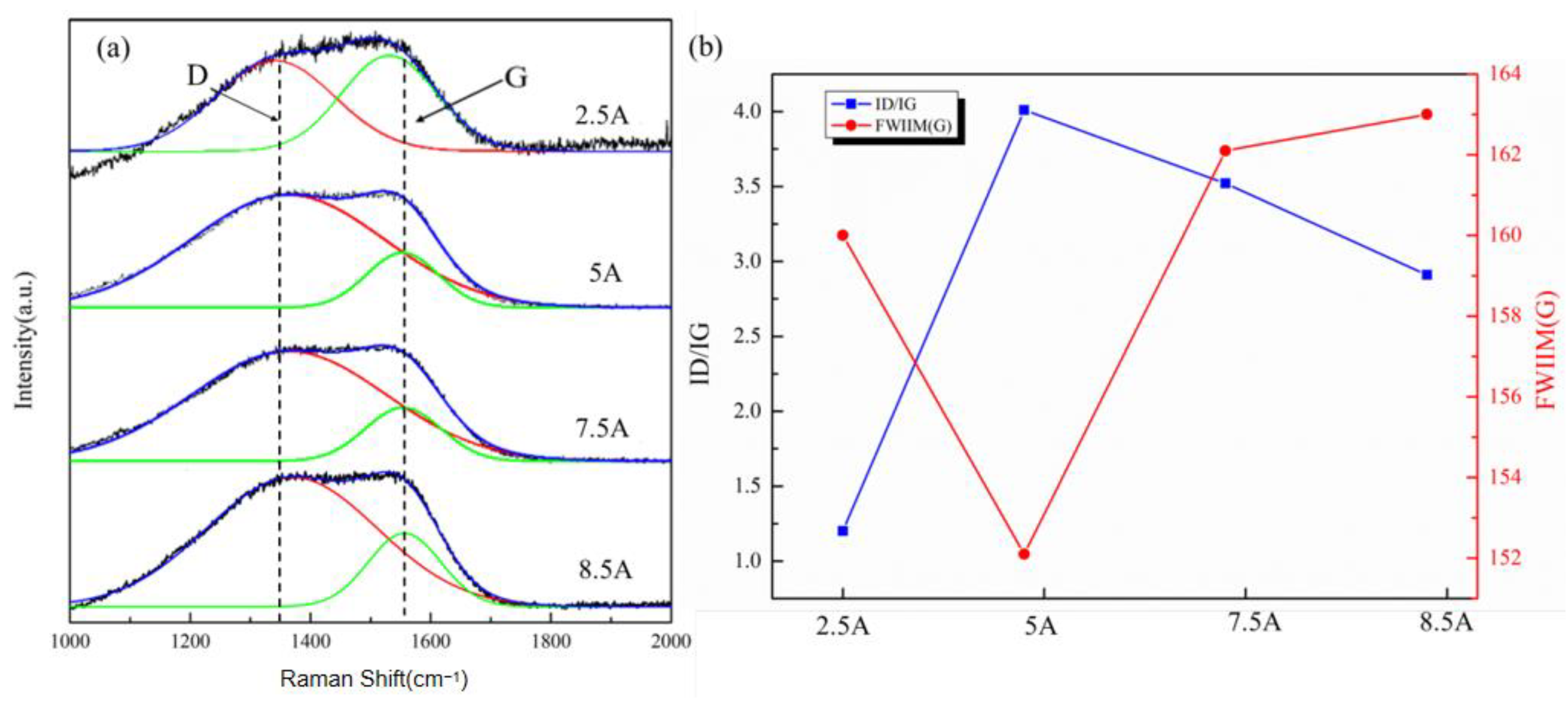
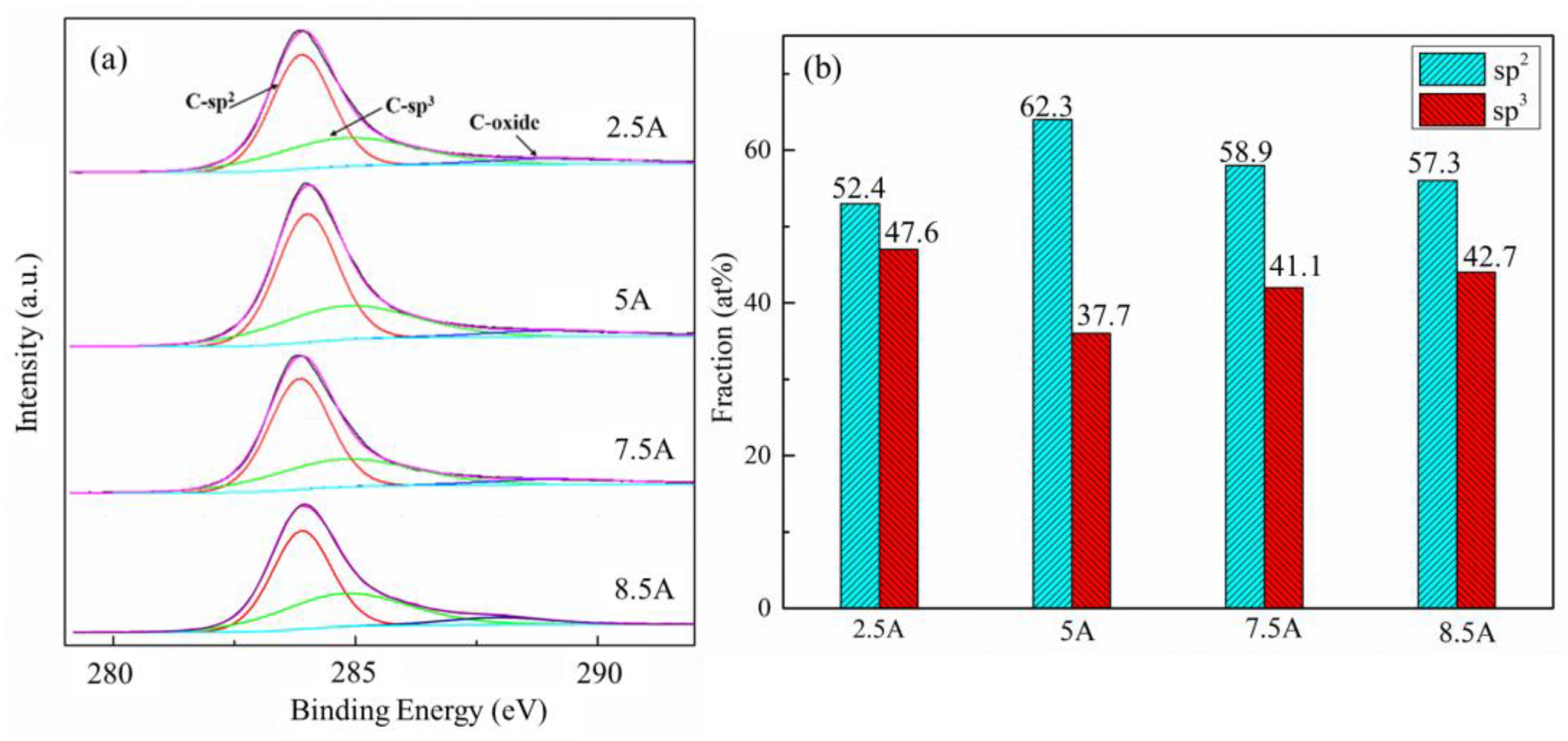
3.1. Morphology and Structure

Figure 1 presents the SEM images of the surfaces and cross-sections of the amorphous carbon coatings deposited under different carbon target sputtering currents. In Figure 1a–c, it can be observed that the deposited amorphous carbon coatings are dense with no apparent defects on the surfaces. At the same time, it is also found that the sputtering current significantly influences the surface density of the coating. When the sputtering current is 5 A, the amorphous carbon coating exhibits the most refined, homogeneous surface structure and compact boundary, indicating the best coating compactness at this sputtering current.
When the sputtering current is at 2.5 A and 7.5 A, the coating surface appears noticeably rougher, with deeper grain boundary structures, which could be due to fewer carbon atoms being sputtered at lower currents, leading to insufficient atomic diffusion, resulting in the formation of a small number of particles with higher heights on the surface. A slower deposition rate allows an excessive number of argon ions to be deposited on the substrate surface, causing larger cluster structures on the surface. Figure 1d shows the surface morphology when the carbon target current is 8.5 A. At this point, the coating surface becomes even rougher, with intense grain boundaries appearing on the surface and large grains. When the sputtering current is high, more carbon atoms are produced, the probability of collisions between atoms increases, the diffusion tension of atoms on the substrate surface decreases, and cluster structures are more likely to appear on the surface, which results in a looser surface of the film and reduced compactness. Figure 1e shows the cross-sectional morphology of the coating when the sputtering current is 5 A. It can be seen that the thickness of the film layer is 623 nm. The coating forms an integral whole, with no obvious grain boundaries appearing during the columnar crystal growth process, indicating a good coating quality.
Figure 2 shows the Raman spectrogram of the amorphous carbon coatings under different sputtering currents. The Raman curve of amorphous carbon is fitted with two peaks: a graphite G peak and a disordered D peak. The Gaussian curve fitting method was used to separate the G and D peaks to evaluate the ID/IG values and G peak positions [36]. The D peak corresponds to the respiratory vibration of the sp2 hybrid ring structure, which is related to the disordered presence of sp2 hybrid bonds in graphite. The G peak generates in-plane vibrations in the sp2 hybrid ring structure, corresponding to the stretching vibrations of two adjacent carbon atoms [37]. By integrating the areas of the G and D peaks, the ratio of IG to ID can be obtained, and the size of the ID/IG ratio can determine the state of sp2 hybrid carbon atoms in the coating. Figure 2a presents the Raman spectra for the four selected sputtering currents. In contrast, Figure 2b displays the statistical results of the peak positions of the G peak and the ID/IG ratios for the amorphous carbon coatings under different sputtering currents. The ID/IG ratio represents the ratio of the areas under the D peak and the G peak, which characterizes the microstructural changes in the amorphous carbon coatings [36]. According to the fitting results, the D peak appears at approximately 1350 cm−1, and the G peak is observed at approximately 1560 cm−1 for all samples, indicating a clear presence of an amorphous carbon structure [38]. Additionally, the ID/IG ratio and the position of the G peak show a trend of initially increasing and then decreasing, suggesting an sp2/sp3 content trend of increasing and then decreasing in the amorphous carbon coatings [39].
The amorphous carbon coating exhibits the highest sp2/sp3 content when the carbon target sputtering current is 5 A. When the carbon target sputtering current is 2.5 A, the initial energy of the C atoms leaving the target material is relatively low, resulting in a lower deposition temperature on the substrate surface and limited atomic diffusion during the deposition process. Therefore, C atoms tend to form C-sp3 bonds. As the sputtering current increases, the number of sputtered atoms and the sputtering energy increase, leading to a higher surface temperature of the coating. In this case, C atoms are more likely to form C-sp2 bonds, increasing the sp2/sp3 content in the amorphous carbon coating (at 5 A). However, when the sputtering current is too high, the atomic energy becomes excessive, continuously bombarding the already deposited coating and causing dissolution, which promotes the formation of C-sp3 bonds. As a result, the sp2/sp3 content decreases in the amorphous carbon coating (at 7.5 A and 8.5 A). The sp2/sp3 content ratio affects the interfacial contact resistance of the coating, suggesting that the coating may have the optimal ICR when the sputtering target current is 5 A [39].
To further analyze the surface structures of the amorphous carbon coatings and obtain the sp2/sp3 hybridization ratio in the coatings, X-ray photoelectron spectroscopy (XPS) was employed to measure the carbon atom hybridization types in the amorphous carbon coatings. The XPS results of the amorphous carbon coatings under different sputtering currents are shown in Figure 3.
The C 1s orbital of the amorphous carbon coatings under different sputtering currents was fitted using a 20% Lorentzian–80% Gaussian function, as shown in Figure 3a. Figure 3 shows three peaks at 284.1 eV, 285.2 eV, and 288.5 eV, representing C-sp2, C-sp3, and C-oxide bonding states. C-oxide formation mainly originates from residual oxygen in the chamber during deposition and the oxidation of the coating in the air.
The integration of the three peaks obtained from fitting the C 1s spectrum provides the percentage of sp2 hybridization, as shown in Figure 3b. As the sputtering current increases, the percentage of C-sp2 hybridization shows a trend of initially increasing and then decreasing, while the percentage of C-sp3 hybridization exhibits an opposite trend of initially decreasing and then increasing. The amorphous carbon coating under a sputtering current of 5 A demonstrates the highest percentage of sp2 hybridization and the lowest percentage of sp3 hybridization, consistent with the Raman spectroscopy analysis results. Therefore, considering the overall analysis, the process with a sputtering current of 5 A is advantageous for obtaining a higher percentage of sp2 hybridization and a denser coating.
Figure 4a shows the XRD pattern of the sample with a sputtering current of 5 A for the carbon target. Due to the amorphous structure of the outermost carbon coating, no diffraction peaks corresponding to the carbon structure can be observed in the XRD spectrum. However, the TiN transition layer exhibits diffraction peaks corresponding to the TiN (112), (004), and (200) crystal planes. Additionally, peaks corresponding to the Ti (100) crystal plane of the substrate can be observed in the XRD pattern of the coating. The presence of the TiN and Ti peaks in the XRD pattern confirms the successful preparation of the TiN transition layer and the underlying Ti layer in the coating. Figure 4b shows the TEM image of the top layer of the sample. In the TEM images, the amorphous carbon structure of the top carbon coating can be seen.

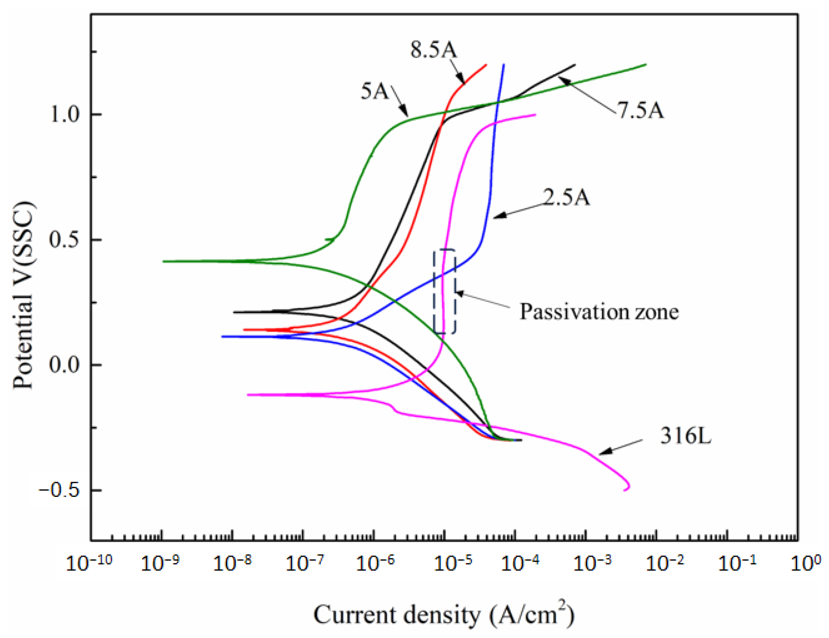
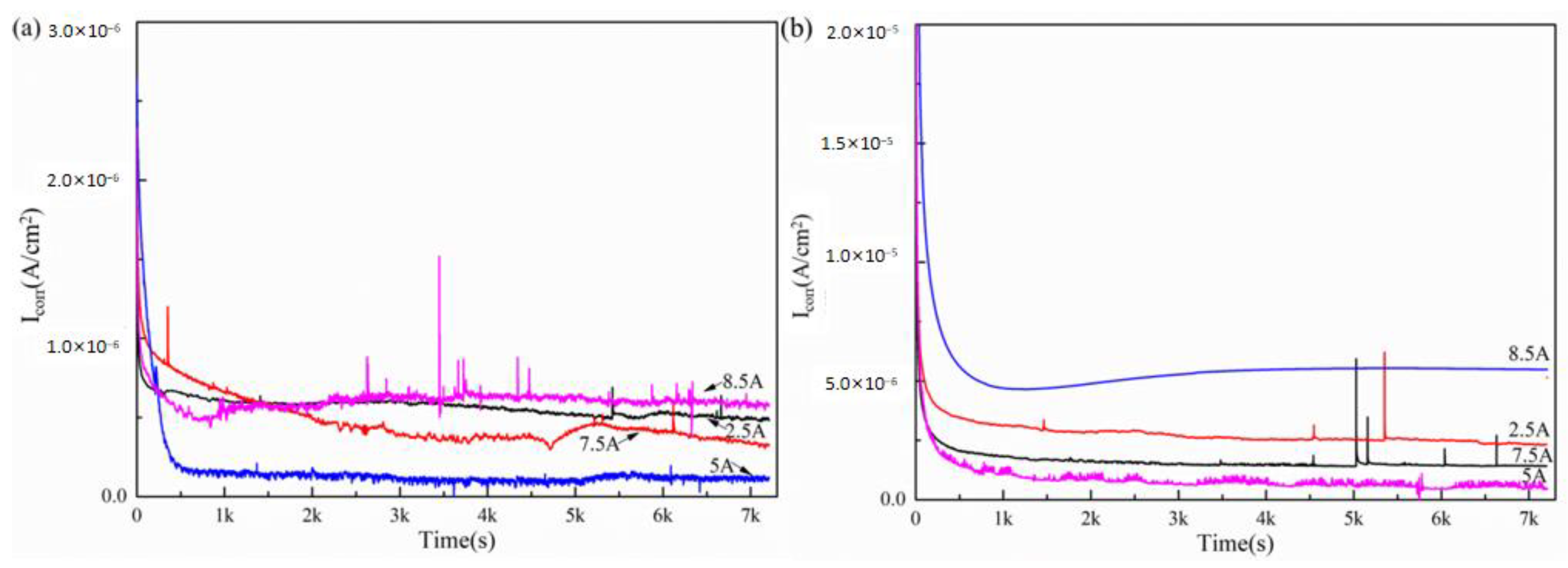
3.2. The Electrochemical Corrosion Behavior

Figure 5 shows the potentiodynamic polarization curves (−0.3 to 1.2 V vs. SCE and vs. SHE) obtained from the electrochemical corrosion tests of the amorphous carbon coatings under different sputtering currents. For the 316L stainless steel substrate, a stable passivation zone can be observed as the electrode potential increases. However, the samples with amorphous carbon coatings do not exhibit an obvious passivation zone. Figure 5 and Table 1 show that the self-corrosion potentials of all the coatings are higher than that of the 316L substrate. The corrosion current densities with the coated samples were reduced by two orders of magnitude compared with bare 316L stainless steel. Generally, a lower corrosion current density and a higher corrosion potential indicate a better corrosion resistance of a sample [40]. The potentiodynamic polarization curves demonstrate the significant improvement in corrosion resistance achieved with the coated samples compared with the bare 316L substrate. This improvement can be attributed to the formation of anti-corrosion coatings on the 316L substrate via magnetron sputtering, effectively protecting the substrate.
Figure 5 and Table 1 show that the self-corrosion potentials of the amorphous carbon coatings initially increased and then decreased with the increase in the sputtering current. The corrosion current densities of the amorphous carbon coatings under four different sputtering currents were 0.43 μA·cm−2, 0.12 μA·cm−2, 0.35 μA·cm−2, and 0.67 μA·cm−2. The coating with a sputtering current of 5 A exhibited the highest corrosion potential and the lowest corrosion current density of 0.12 μA·cm−2. This result is mainly attributed to the appropriate sputtering current that could stimulate the deposition of an optimal amount of atoms on the substrate. The coating was loose and lacked density when the sputtering current was low (2.5 A). With an increased sputtering current (5 A), the atomic deposition of the coating was at an optimal level, resulting in a dense surface. However, when the sputtering current was too high (7.5 A and 8.5 A), excessive sputtered atoms bombarded the already deposited coating, leading to defects and reduced corrosion resistance. A porous coating surface allows the corrosive solution to penetrate along the grain boundaries, resulting in intergranular corrosion and poor coating corrosion resistance. Conversely, a dense surface significantly hinders the penetration of the corrosive solution, thereby improving the corrosion resistance of the coating. Furthermore, it is worth noting that when the potential was above +1.0 V(vs. SCE), the corrosion current density rapidly increased, indicating that the coating had undergone a more severe anodic oxidation behavior. This behavior can be attributed to the increased corrosion tendency at higher potentials, resulting in the intergranular corrosion of the coating at grain boundaries, as well as severe intergranular corrosion at the interface between CrN and amorphous carbon.
Figure 6 shows the potentiostatic polarization curves (+0.6 V vs. SCE; +1.1 V vs. SHE) of the amorphous carbon coatings under different sputtering currents, and Table 2 presents the corrosion current density values of the coatings after 7200 s of stabilization. All the potentiodynamic polarization curves initially exhibit relatively high corrosion current densities, rapidly decreasing over time due to forming, and finally, the values maintain stability [41]. After 2 h of potentiostatic corrosion (Table 3), it can be observed that the coating with a sputtering current of 5 A still exhibits the lowest corrosion current densities of 0.121 μA·cm−2 (+0.6 V vs. SCE) and 0.453 μA·cm−2 (+1.1 V vs. SHE). These values are below the standard of 1 μA·cm−2 set by the DOE, consistent with the results of the potentiodynamic polarization curves.

3.3. Interfacial Contact Resistance (ICR)
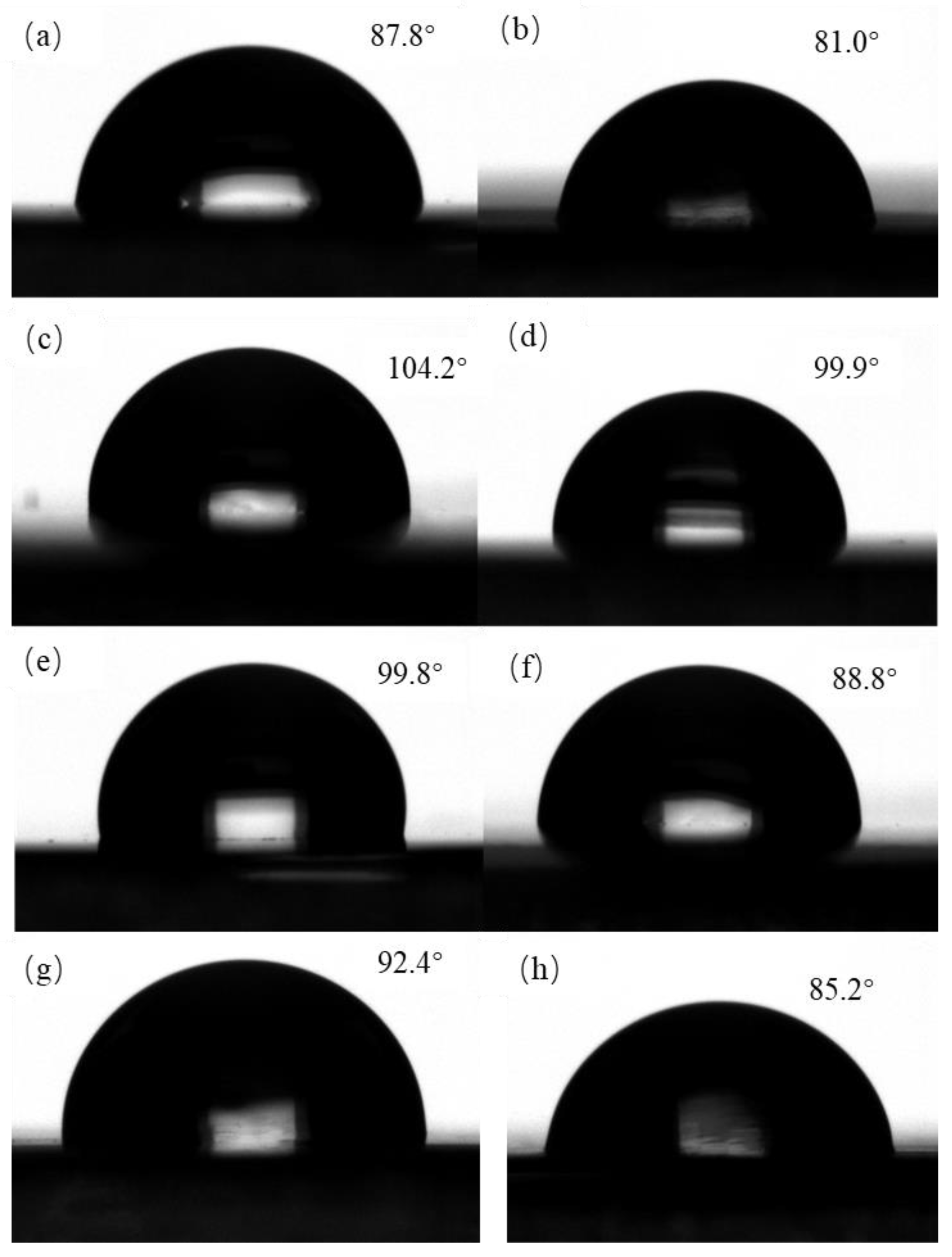
Figure 7 shows the interfacial contact resistance of the amorphous carbon coatings before and after corrosion under a compression force of 1.4 MPa. In the figure, it can be observed that the uncoated 316L stainless steel exhibits a high contact resistance. However, when the conductive amorphous carbon coating replaces the poor-conductivity passive film on the stainless steel surface, the contact resistance (ICR value) significantly decreases. Before and after corrosion, the contact resistance values of the four amorphous carbon coatings are below 10 mΩ·cm2, primarily due to the excellent conductivity of the sp2 hybridized carbon in the fabricated coatings. Additionally, it can be observed in the figure that the interfacial contact resistance initially decreases and then increases with the increasing sputtering current. The coating with a sputtering current of 5 A exhibits the lowest contact resistance. The electrical conductivity of an amorphous carbon coating is mainly related to the density of the coating and the sp2 hybrid ratio. The denser the coating and the higher the sp2 content, the better the conductivity of the coating. The density and high energy of the coating effectively reduce the scattering rate of the coating when transporting electrons.
The change in the contact resistance after electrochemical corrosion is also an essential factor in evaluating the performance of a fuel cell stack after operation. In Figure 7, it can be observed that the contact resistance of the amorphous carbon coating increases to varying degrees after electrochemical corrosion. Specifically, the contact resistance increases by 1.9 mΩ·cm2 for the 2.5 A coating, 1.3 mΩ·cm2 for the 5 A coating, 2.3 mΩ·cm2 for the 7.5 A coating, and 7.8 mΩ·cm2 for the 8.5 A coating. The interface contact resistance of the bipolar plate is largely related to the surface roughness of the coating. Among the microsurface morphologies, the coating with a 5 A sputtering current exhibits the smoothest surface. When measuring contact resistance, the contact area between the sample and the carbon paper is more extensive, resulting in a more negligible interface contact resistance. The increase in contact resistance is attributed to the electrochemical corrosion that damages the structure of the amorphous carbon coating and leads to the formation of an oxide layer on the surface, thereby reducing the conductivity of the coating. When the sputtering current is 8.5 A, the coating is rough with wide grain boundaries and large grain size. As a result, surface corrosion becomes more severe after corrosion, which results in a significant increase in contact resistance. However, with a 5 A sputtering current, after 2 h of constant potential polarization corrosion, the increase in interface contact resistance for the amorphous carbon coating is the smallest, meeting the DOE standard of contact resistance of less than 10 mΩ·cm2.

3.4. Contact Angle

Figure 8 depicts the surface contact angles of the amorphous carbon coatings at different sputtering currents before and after corrosion. It can be observed that the contact angles exhibit a trend of initially increasing and then decreasing with the sputtering current. For the amorphous carbon coating obtained at a sputtering current of 2.5 A, the contact angle before corrosion is 87.8°, which falls to 81° after corrosion, resulting in a decrease of 6.8°. At a sputtering current of 5 A, the contact angles before and after corrosion are the highest, with the smallest difference of 5.3° between them. The polar component of surface energy significantly influences the water contact angle. The polar component in the coating interacts strongly with water molecules, which enhances the coating’s hydrophilicity. Therefore, a lower polar component on the coating surface indicates stronger hydrophobicity. In the case of the amorphous carbon coating obtained at a sputtering current of 5 A, the surface is more compact, with more sp2 hybridized clusters. The sp2 bonds possess weak polarity, reducing the surface energy and resulting in stronger hydrophobicity.

4. Conclusions

This study investigated the influence of different carbon sputtering currents on the structure and properties of amorphous carbon coatings, and the following conclusions are drawn. With the increasing carbon sputtering current, the deposition energy of carbon atoms varied, resulting in the gradual densification followed by the gradual loosening of the coating surfaces.
As the carbon sputtering current increased, the sp2 hybridization ratio of carbon atoms in the amorphous carbon coatings initially increased and then decreased. The TiN/C composite coating obtained at a carbon sputtering current of 5 A exhibited a finer and more uniform grain structure and denser bonding, demonstrating the best corrosion resistance. The surface density of a coating greatly affects its corrosion resistance. The rough surfaces of samples with carbon target currents of 7.5 A and 8.5 A exhibited poor corrosion resistance. Furthermore, compared with the other samples, the sample at a 5 A sputtering current showed the highest sp2/sp3 ratio, resulting in the lowest interfacial contact resistance of 3.9 mΩ·cm2. After a 2 h constant potential polarization corrosion resistance test, the conductivity and hydrophobicity of the amorphous carbon coatings were measured.
The coating obtained at a carbon sputtering current of 5 A exhibited the least performance degradation, with the contact resistance only increasing from 3.9 mΩ·cm2 to 5.2 mΩ·cm2 and the contact angle decreasing from 104.2° to 99.9°, indicating that the TiN/C composite coating maintained good conductivity and hydrophobicity even after corrosion.

Funding

This research was supported by the Shanghai Engineering Research Center for Metal Parts Green Remanufacture (no. 19DZ2252900) of the Shanghai Engineering Research Center Construction Project.

Institutional Review Board Statement

Not applicable.

Informed Consent Statement

Not applicable.

Data Availability Statement

The data generated or analyzed during this study are included in this article.

Conflicts of Interest

The author declares no conflict of interest.

References

  1. Zhao, J.; Li, X. A review of polymer electrolyte membrane fuel cell durability for vehicular applications: Degradation modes and experimental techniques. Energy Convers. Manag. 2019, 199, 112022. [Google Scholar] [CrossRef]
  2. Chen, H.; Zhao, X.; Zhang, T.; Pei, P. The reactant starvation of the proton exchange membrane fuel cells for vehicular applications: A review. Energy Convers. Manag. 2019, 182, 282–298. [Google Scholar] [CrossRef]
  3. Peng, L.; Yi, P.; Lai, X. Design and manufacturing of stainless steel bipolar plates for proton exchange membrane fuel cells. Int. J. Hydrogen Energy 2014, 39, 21127–21153. [Google Scholar] [CrossRef]
  4. Tang, Y.; Yuan, W.; Pan, M.; Wan, Z. Feasibility study of porous copper fiber sintered felt: A novel porous flow field in proton exchange membrane fuel cells. Int. J. Hydrogen Energy 2010, 35, 9661–9677. [Google Scholar] [CrossRef]
  5. Yi, P.; Zhang, D.; Qiu, D.; Peng, L.; Lai, X. Carbon-based coatings for metallic bipolar plates used in proton exchange membrane fuel cells. Int. J. Hydrogen Energy 2019, 44, 6813–6843. [Google Scholar] [CrossRef]
  6. Lee, J.-B.; Oh, I.H. Electrochemical characteristics and interfacial contact resistance of multi-layered Ti/TiN coating for metallic bipolar-plate of polymer electrolyte membrane fuel cells. Met. Mater. Int. 2016, 20, 629–639. [Google Scholar] [CrossRef]
  7. Hermann, A.; Chaudhuri, T.; Spagnol, P. Bipolar plates for PEM fuel cells: A review. Int. J. Hydrogen Energy 2005, 30, 1297–1302. [Google Scholar] [CrossRef]
  8. Song, Y.; Zhang, C.; Ling, C.-Y.; Han, M.; Yong, R.-Y.; Sun, D.; Chen, J. Review on current research of materials, fabrication and application for bipolar plate in proton exchange membrane fuel cell. Int. J. Hydrogen Energy 2020, 45, 29832–29847. [Google Scholar] [CrossRef]
  9. Wang, H.; Turner, J.A.; Li, X.; Bhattacharya, R. SnO2:F coated austenite stainless steels for PEM fuel cell bipolar plates. J. Power Sources 2007, 171, 567–574. [Google Scholar] [CrossRef]
  10. Zhang, J.; Jin, J.; Tao, Y.; Cao, R.; Kou, X.; Tian, X. Investigation of corrosion properties with Ni–P/TiNO coating on aluminum alloy bipolar plates in proton exchange membrane fuel cell. Int. J. Hydrogen Energy 2022, 47, 22165–22179. [Google Scholar] [CrossRef]
  11. Yan, P.; Cao, S.; Ying, T.; Yang, Y.; Cao, F.; Zeng, X. Novel Graphite Paper/Cu-Coated Magnesium as Bipolar Plates for Ultra-lightweight Proton Exchange Membrane Fuel Cells. J. Electrochem. Soc. 2023, 170, 054510. [Google Scholar] [CrossRef]
  12. Zhang, P.C.; Han, Y.T.; Shi, J.F.; Li, T.; Wang, H.Y.; Wang, X.Y.; Sun, J.C. ZrC Coating Modified Ti Bipolar Plate for Proton Exchange Membrane Fuel Cell. Fuel Cells 2020, 20, 540–546. [Google Scholar] [CrossRef]
  13. Mi, B.; Chen, Z.; Wang, Q.; Li, Y.; Qin, Z.; Wang, H. Properties of C-doped CrTiN films on the 316L stainless steel bipolar plate for PEMFC. Int. J. Hydrogen Energy 2021, 46, 32645–32654. [Google Scholar] [CrossRef]
  14. Mi, B.; Wang, H.; Wang, Q.; Cai, J.; Qin, Z.; Chen, Z. Corrosion resistance and contact resistance properties of Cr-doped amorphous carbon films deposited under different carbon target current on the 316L stainless steel bipolar plate for PEMFC. Vacuum 2022, 203, 111263. [Google Scholar] [CrossRef]
  15. Yin, Q.; Wang, X.-W.; Liu, S.; Wang, X.-Z.; Fu, X.-Z.; Luo, J.-L. High corrosion resistance of reduced graphene oxide coated 316L stainless steel bipolar plate for proton exchange membrane fuel cell prepared by a facile method. Mater. Chem. Phys. 2022, 290, 126663. [Google Scholar] [CrossRef]
  16. Steinhorst, M.; Auinger, M.; Roch, T.; Leyens, C. Modelling and corrosion of coated stainless steel substrates for bipolar plates at different temperatures. J. Appl. Electrochem. 2023, 53, 1491–1503. [Google Scholar] [CrossRef]
  17. Hu, Z.; Yuan, L.; Luo, H.; Jin, Y.; Chen, Z. Effects of Nitrogen Flow Rate on the Performances of Cathodic Arc Deposited TiN Films on 316L Stainless Steels as Bipolar Plates for the Proton--Exchange Membrane Fuel Cell. Steel Res. Int. 2023, 94, 2300089. [Google Scholar] [CrossRef]
  18. Zhang, W.-J.; Wang, Y.-L. Performance of TiC coating prepared by in situ conversion of organic carbon film on 316L bipolar plate. J. Iron Steel Res. Int. 2023, 30, 1562–1573. [Google Scholar] [CrossRef]
  19. Chen, L.; Liu, R.; Zhang, B.; Lv, J.; Zhang, J. Nano-Cr2N dominated films with high conductivity and strong corrosion resistance for Ti bipolar plates. Mater. Des. 2022, 224, 111305. [Google Scholar] [CrossRef]
  20. Chen, M.; Ding, J.C.; Kwon, S.-H.; Wang, Q.; Zhang, S. Corrosion resistance and conductivity of NbN-coated 316L stainless steel bipolar plates for proton exchange membrane fuel cells. Corros. Sci. 2022, 196, 110042. [Google Scholar] [CrossRef]
  21. Li, H.; Xin, Y.; Komatsu, K.; Guo, P.; Ma, G.; Ke, P.; Lee, K.-R.; Saito, H.; Wang, A. Controlling the compactness and sp2 clusters to reduce interfacial damage of amorphous carbon/316L bipolar plates in PEMFCs. Int. J. Hydrogen Energy 2022, 47, 11622–11632. [Google Scholar] [CrossRef]
  22. Yan, W.; Zhang, Y.; Chen, L.; Luo, J.; Pang, P.; Zhang, X.; Liao, B.; Ying, M. Corrosion behavior and interfacial conductivity of amorphous hydrogenated carbon and titanium carbide composite (a-C: H/TiC) films prepared on titanium bipolar plates in PEMFCs. Diam. Relat. Mater. 2021, 120, 108628. [Google Scholar] [CrossRef]
  23. Taherian, R.; Mohammadi, M.; Samiei, Z. Investigation of graphite conductive adhesive coated on SS316L used for bipolar plates of proton-exchange membrane fuel cell. J. Adhes. Sci. Technol. 2021, 36, 1094–1111. [Google Scholar] [CrossRef]
  24. Li, W.; Liu, L.; Wang, Y.; Li, H.; Li, Z. Evaluation of vacuum heat-treated α-C films for surface protection of metal bipolar plates used in polymer electrolyte membrane fuel cells. Int. J. Hydrogen Energy 2021, 46, 22983–22997. [Google Scholar] [CrossRef]
  25. Hou, K.; Yi, P.; Li, X.; Peng, L.; Lai, X. The effect of Cr doped in amorphous carbon films on electrical conductivity: Characterization and mechanism. Int. J. Hydrogen Energy 2021, 46, 30841–30852. [Google Scholar] [CrossRef]
  26. Yi, P.; Zhang, W.; Bi, F.; Peng, L.; Lai, X. Microstructure and properties of a-C films deposited under different argon flow rate on stainless steel bipolar plates for proton exchange membrane fuel cells. J. Power Sources 2019, 410–411, 188–195. [Google Scholar] [CrossRef]
  27. Bi, F.; Hou, K.; Yi, P.; Peng, L.; Lai, X. Mechanisms of growth, properties and degradation of amorphous carbon films by closed field unbalanced magnetron sputtering on stainless steel bipolar plates for PEMFCs. Appl. Surf. Sci. 2017, 422, 921–931. [Google Scholar] [CrossRef]
  28. Jia, Q.; Mu, Z.; Zhang, X.; Zhang, B.; Liu, R.; Gao, K.; Yu, Y.; Lai, Z.; Zhang, J. Electronic conductive and corrosion mechanisms of dual nanostructure CuCr-doped hydrogenated carbon films for SS316L bipolar plates. Mater. Today Chem. 2021, 21, 100521. [Google Scholar] [CrossRef]
  29. Gou, Y.; Jiang, G.; Geng, J.; Shao, Z. Properties of NbC/a-C:H films on titanium bipolar plates for proton exchange membrane fuel cells. Fuel Cells 2022, 23, 51–59. [Google Scholar] [CrossRef]
  30. Ouyang, C.; Xun, D. Carbon/Graphite Sheets/PTFE-Coated Porous Titanium as the Bipolar Plate by Hydrothermal Treatment. Coatings 2022, 12, 1649. [Google Scholar] [CrossRef]
  31. Gou, Y.; Jiang, G.; Hao, J.; Shao, Z.; Wei, Z. A corrosion mechanism of NbC/α-C:H films for metallic bipolar plates in proton exchange membrane fuel cell cathode based on percolation model. Surf. Coat. Technol. 2022, 445, 128711. [Google Scholar] [CrossRef]
  32. Meng, W.; Zhu, H.; Wang, X.; Li, G.; Fan, Y.; Sun, D.; Kong, F. Electrochemical Behavior and Surface Conductivity of C/TiC Nanocomposite Coating on Titanium for PEMFC Bipolar Plate. Metals 2022, 12, 771. [Google Scholar] [CrossRef]
  33. Mi, B.; Wang, Q.; Qi, T.; Qin, Z.; Chen, Z.; Wang, H. Performance and structure of Ti-doped amorphous carbon/CrN/Ti multilayer coating deposited on 316L stainless steel for use as bipolar plate in proton exchange membrane fuel cell. J. Alloys Compd. 2023, 943, 169080. [Google Scholar] [CrossRef]
  34. Papadias, D.D.; Ahluwalia, R.K.; Thomson, J.K.; Meyer, H.M.; Brady, M.P.; Wang, H.; Turner, J.A.; Mukundan, R.; Borup, R. Degradation of SS316L bipolar plates in simulated fuel cell environment: Corrosion rate, barrier film formation kinetics and contact resistance. J. Power Sources 2015, 273, 1237–1249. [Google Scholar] [CrossRef]
  35. Fukutsuka, T.; Yamaguchi, T.; Miyano, S.-I.; Matsuo, Y.; Sugie, Y.; Ogumi, Z. Carbon-coated stainless steel as PEFC bipolar plate material. J. Power Sources 2007, 174, 199–205. [Google Scholar] [CrossRef]
  36. Forouzanmehr, M.; Reza Kashyzadeh, K.; Borjali, A.; Ivanov, A.; Jafarnode, M.; Gan, T.H.; Wang, B.; Chizari, M. Detection and analysis of corrosion and contact resistance faults of TiN and CrN coatings on 410 stainless steel as bipolar plates in PEM fuel cells. Sensors 2022, 22, 750. [Google Scholar] [CrossRef] [PubMed]
  37. Dai, W.; Ke, P.; Moon, M.-W.; Lee, K.-R.; Wang, A. Investigation of the microstructure, mechanical properties and tribological behaviors of Ti-containing diamond-like carbon films fabricated by a hybrid ion beam method. Thin Solid Film. 2012, 520, 6057–6063. [Google Scholar] [CrossRef]
  38. Li, H.X.; Xu, T.; Chen, J.M.; Zhou, H.; Liu, H. The effect of applied dc bias voltage on the properties of a-C:H films prepared in a dual dc–rf plasma system. Appl. Surf. Sci. 2004, 227, 364–372. [Google Scholar] [CrossRef]
  39. Qi, Q.; Zhang, W.Z.; Shi, L.Q.; Zhang, B. Preparation of single-crystal TiC (111) by radio frequency magnetron sputtering at low temperature. Thin Solid Film. 2012, 520, 6882–6887. [Google Scholar] [CrossRef]
  40. Zendejas Medina, L.; da Costa, M.T.; Paschalidou, E.M.; Lindwall, G.; Riekehr, L.; Korvela, M.; Fritze, S.; Kolozsvári, S.; Gamstedt, E.K.; Nyholm, L.; et al. Enhancing corrosion resistance, hardness, and crack resistance in magnetron sputtered high entropy CoCrFeMnNi coatings by adding carbon. Mater. Des. 2021, 205, 109711. [Google Scholar] [CrossRef]
  41. Alishahi, M.; Mahboubi, F.; Mousavi Khoie, S.M.; Aparicio, M.; Hübner, R.; Soldera, F.; Gago, R. Electrochemical behavior of nanocrystalline Ta/TaN multilayer on 316L stainless steel: Novel bipolar plates for proton exchange membrane fuel-cells. J. Power Sources 2016, 322, 1–9. [Google Scholar] [CrossRef]
Figure 1. Microsurface and cross-sectional morphologies of amorphous carbon coatings under different sputtering currents: (a) 2.5 A, (b) 5 A, (c) 7.5 A, and (d) 8.5 A. (e) Cross-sectional view of the sample at 5 A.
Coatings 13 01494 g001
Figure 2. Raman spectroscopy of amorphous carbon coatings under different sputtering currents: (a) Raman peak spectra and (b) ID/IG and FWHM(G) (full width at half maximum of the G peak).
Coatings 13 01494 g002
Figure 3. XPS results of carbon atom hybridization in amorphous carbon coatings under different sputtering currents: (a) XPS peak fitting results and (b) sp2 and sp3 hybridization percentages.
Coatings 13 01494 g003
Figure 4. XRD and TEM pattern of the sample with a sputtering current of 5 A for the carbon target: (a) XRD pattern (b) TEM image.
Coatings 13 01494 g004
Figure 5. Potentiodynamic polarization curves of amorphous carbon coatings under different sputtering currents.
Coatings 13 01494 g005
Figure 6. (a) Potentiostatic polarization curves at +0.6 V vs. SCE; (b) potentiostatic polarization curves at +1.1 V vs. SHE.
Coatings 13 01494 g006
Figure 7. Interfacial contact resistances of four coatings before and after +1.1 V potentiostatic polarization under a compaction force of 1.40 MPa.
Coatings 13 01494 g007
Figure 8. Photos of the four coatings before and after +1.1 V potentiostatic polarization: (a,b) 2.5 A, (c,d) 5 A, (e,f) 7.5 A, and (g,h) 8.5 A.
Coatings 13 01494 g008
Table 1. Stainless steel composition table.
Stainless SteelCrNiMoAlCMnSi
Chemical composition12.24%–13.25%7.5%–8.5%2.0%–2.5%0.90%–1.35%≤0.030≤2.00≤1.00
Table 2. Corrosion current densities and self-corrosion potentials of the substrate and coatings in a simulated PEMFC environment.
Sample316L2.5 A5 A7.5 A8.5 A
Icorr/(μA·cm−2)290.430.120.350.67
Ecorr/mV(SSC)−118.2113.3413.8210.9140.8
Table 3. Potentiostatic corrosion current densities of substrate and coatings in simulated PEMFC environment.
Sample2.5 A5 A7.5 A8.5 A
+0.6 V vs. SCE (μA·cm−2)0.4800.1210.3250.582
+1.1 V vs. SHE (μA·cm−2)5.4760.4535.139140.8
Disclaimer/Publisher’s Note: The statements, opinions and data contained in all publications are solely those of the individual author(s) and contributor(s) and not of MDPI and/or the editor(s). MDPI and/or the editor(s) disclaim responsibility for any injury to people or property resulting from any ideas, methods, instructions or products referred to in the content.

