
Tetrahedral Amorphous Carbon Coatings with Al Incorporation Deposited by a Hybrid Technique of Sputtering and Arc Evaporation

1
School of Electromechanical Engineering, Guangdong University of Technology, Guangzhou 510006, China
2
Guangdong Dtech Technology Co., Ltd., Dongguan 523940, China
*
Author to whom correspondence should be addressed.
Coatings 2024, 14(1), 142; https://doi.org/10.3390/coatings14010142
Submission received: 27 December 2023
/
Revised: 12 January 2024
/
Accepted: 18 January 2024
/
Published: 21 January 2024
(This article belongs to the Special Issue Advances in Deposition and Characterization of Hard Coatings)
Abstract
:In this paper, tetrahedral amorphous carbon (ta-C) coatings containing Al were deposited by a hybrid technique of sputtering and arc evaporation. The influence of Al incorporation in the structure and properties of the ta-C coatings were studied as a function of the Al concentration. It is found that Al tends to form a Al-O-C bond when the Al concentration is small. An Al-C bond was detected when the Al concentration is high. Al can facilitate the graphitization of the ta-C coatings and the graphite cluster size as well as the sp2/sp3 ratio of the coatings increase as the Al concentration increases. The decline of the sp3 fraction causes the drop in the hardness of the coatings. The incorporation of Al can effectively decrease the residual stress of the ta-C coatings. During friction tests, Al can facilitate the formation of the sp2-rich graphitic tribo-layer and decrease the friction coefficient. Nevertheless, the decline of the hardness due to the Al incorporation will result in the increase in the wear rate of the coating. It is believed that the ta-C coating with a proper concentration of Al appears to achieve a good comprehensive performance with high hardness, low residual stress, and a low friction coefficient and wear rate.
1. Introduction
Tetrahedral amorphous carbon (ta-C) coatings with a high content of sp3-C bonds have characteristics similar to diamond, i.e., high hardness, high resistivity, good optical transparency, chemical inertness, and a low friction coefficient [1]. Compared to diamond coatings deposited by chemical vapor deposition with high temperatures and seed crystals, ta-C coatings could be prepared by relatively economical physical vapor deposition, e.g., vacuum cathode arc deposition without heating and seed crystals [2,3]. Therefore, ta-C coatings have been widely used on tools and spare parts for improving their performance and lifetime. However, the high level compressive stress that is produced in the process of forming sp3 bonds causes the delamination of the ta-C coatings and makes the coatings hard to grow thick and severely limits their practical application in protection.
Metal element doping has been employed to release the high compressive stress of the carbon-based coatings. So far, many metallic elements (Ti, Cr, Cu, Al, etc.) have been used to modify the carbon based coatings (e.g., diamond-like carbon, DLC) [4,5,6,7]. Among these metal elements, Al doping is regarded as a crucial method for decreasing the compressive stress of the carbon-based coatings [8]. In addition, Al can promote the rearrangement of C atoms, leading to graphitization transformation and the formation of a graphite phase, which plays a solid lubrication role and can significantly reduce friction [9,10]. It is interesting that in carbon based coatings, Al tends to exist as Al-O or Al-O-C due to Al being highly reactive with O which originates from the residual water vapor, air, etc., in the vacuum chamber. The existence form of Al is also related to the carbon structure of the carbon-based coatings. Guo et al. [11] deposited hydrogen-free Al-DLC coatings by a high impulse power magnetron sputtering (HiPIMS) technology with an Al-C composite target and found that Al tends to bond with O to form Al-O rather than Al-C. D. Peckus et al. [12] prepared hydrogenated and hydrogen free Al-DLC coatings using a magnetron sputtering method, and found that Al-O-C was observed in hydrogenated Al-DLC coatings while Al2O3, Al-O-C, and Al4C3 were observed in hydrogen-free Al-DLC coatings when Al content exceeds 20 at.%. Ding et al. [13] deposited ta-C:Al coatings by combining a filtered cathodic vacuum arc technique (FCVA) of carbon with magnetron sputtering of Al. They argue that metallic Al nanoparticles are formed in the ta-C coatings when the Al content reached to 14 at.%, but carbide bonds (e.g., Al-C) were not detected even the Al content reached 39.6 at.%. In our previous works [10], we prepared hydrogenated Al-DLC coatings by a hybrid ion beam system composed of an anode-layer ion source and a magnetron sputtering. The deposited layers had nano-stripe structures composed of amorphous aluminum oxides in the coatings. It is clear that both the carbon matrix and the deposition method would influence the existence form of the doping Al.
A cathodic vacuum arc (CVA) has been widely used to prepare ta-C coatings due to its facile and low-cost features. In addition, CVA shows a higher growth rate in the deposition of the ta-C coatings compared with FCVA [2]. Furthermore, the ta-C coatings deposited by CVA have higher sp3/sp2 and density compared with the DLC coatings by the magnetron sputtering and ion source [14]. Therefore, the impact of the Al doping on the structure and properties of ta-C might be different from those of DLC coatings. In this paper, ta-C coatings with Al incorporation (ta-C:Al) were deposited by a hybrid technique of a CVA of pure graphite target and magnetron sputtering of a pure Al target. The structure, chemical composition, carbon matrix structure, residual stress, and mechanical properties, as well as the tribological performance of the ta-C:Al coatings, were studied systematically. The influence of active Al on the microstructure and properties of the ta-C:Al coatings were discussed in terms of the existence of the Al dopants.
2. Experimental Details
Series of ta-C:Al coatings were deposited on silicon wafers and a cemented carbide (WC-6Co alloy) block (16 × 16 × 5 mm) by a hybrid technique consisting of CVA and magnetron sputtering. The CVA unit was equipped with the graphite target (99.95 at.%) with a diameter of 100 cm and the magnetron sputtering source was equipped with the aluminum target (99.97 at.%) with a size of 470 mm (length) × 210 mm (width). The distance from the targets to the substrate holder was roughly 50 mm. The substrate holder was fixed to the central rotary table and revolved with the central rotary table at a speed of 6 rpm. The substrates were cleaned by an ultrasonic bath of acetone for 20 min firstly, and then were further cleaned by a bath of alcohol for 20 min. The substrates, after being cleaned, were put in the thermostat oven to dry. The substrates were fixed on the substrate holder in the chamber and then the chamber was pumped to 3 × 10⁻³ Pa. Subsequently, the substrates and the chamber were cleaned by an Ar glow discharge with −900 V bias voltage and 1 Pa pressure for 15 min and further etched by an Ar+ beam produced by the anode-layer ion source with an bias voltage of −600 V for 20 min before coating process. The current of the anode-layer ion source was 5 A. A metallic Al layer of about 200 nm was deposited on the substrates prior the ta-C:Al coatings. During the deposition process of the ta-C:Al coatings, Ar with a flux of 100 sccm was introduced into the vacuum chamber. The chamber pressure was kept around 0.7 Pa. The current for the cathode arc evaporation of the graphite target was 100 A. The DC power for the magnetron sputtering of the aluminum target was ranging from 120 W to 2.8 kW to tune the content of the doping Al in the coatings. A bias voltage of −50 V was applied on the substrates and the deposition time of ta-C was 30 min.
A scanning electron microscope (SEM, HITACHI UHR FE-SEM SU8200, Japan) was used for observing the cross-sectional morphology of the as-deposited coatings. The coating thickness was detected according to the cross-sectional SEM images. An X-ray photoelectron spectroscopy (XPS, Thermo ESCALAB 250Xi, MA USA) with Al (mono) Kα (hv = 1486.6 eV) was employed to characterize the elemental compositions and chemical bonds of the as-deposited coatings. The step size of the XPS spectra was 1 eV. The high-resolution XPS spectra were taken for the chemical details. The pass energy and step size were 100 eV and 0.05 eV, respectively. The XPS spectra were calibrated according to the typical C-C peak around the binding energy of 284.6 eV in C1s spectra of amorphous carbon. An Ar+ ion beam with energy of 2 kV was used to etch the coatings before XPS measurement to clean up pollution and oxide on the coating surface. The etching depth was about 10 nm. Peak fitting of the XPS spectra of the coatings was carried out on the CasaXPS software (2.2.73) using Shirley-type background and asymmetric Lorentzian/Gaussian (70%/30%) peak shapes. The concentrations of the elements in the coatings were also calculated according to the atomic sensitivity factors and the relative area ratios of the peaks in the XPS spectra of the coatings. In addition, the carbon atomic structure of the coating was characterized using Raman spectroscopy (LabRAM HR Evolution, France). A He-Ne laser with a wavelength of 632.8 nm was used as the incident light from. The laser output was approximately 0.8 mW and the laser intensity was reduced to 10% of the laser power by a neutral density filter to avoid sample damage. The measurement positions were concentrated at a magnification of 100× in the optical microscope and a light spot diameter ≤ 1 μm. The Raman scattering range spanned from 800 cm−1 to 2000 cm−1 The spectral resolution was approximately 1 cm−1.
A nanoindentation tester (CSM, TTX-NHT, Switzerland) was applied to measure the coating hardness and elastic modulus with a Berkovich diamond indenter under constant load of 5 mN. The indentation depths were controlled to approximately 10% of the coating thicknesses to minimize the influence of the soft substrate. Fifteen replicate indentations were made for one sample to reduce errors. The residual stress of the pure ta-C and ta-C:Al coatings was measured using an FST-1000 stress tester (Supro, China) by measuring the curvature change of the substrate before and after the coating deposition and calculated from the Stoney’s equation [15]. A ball-on-plate tribometer (CSM, THT, Switzerland) was used to measure the tribological performances of the coatings with using an Al2O3 ball (6 mm in diameter) as a counterpart material. The friction tests were conducted with a rotational speed of 800 r/min under a load of 2 N (the initial Hertzian contact pressure was approximately 0.2 GPa) at an ambient air condition (relative humidity: 50% ± 5%, RT), and the total wear duration was 10,000 cycles. A surface profilometer (Olympus OLS4100, Japan) was employed to measure the wear track profiles of the ta-C:Al coatings after the friction test and the wear morphology was also observed by SEM. Raman spectrum was also used to characterize the changes of the carbon structure of the wear tracks on the coatings after friction. The Archard equation k = V/(F × L) was used to calculate the wear rates of the coatings with different Al concentrations. In the equation, k, V, F, and N denote the wear rate (mm3/N⋅m), the wear volume (mm3), the normal load (N), and L and the total sliding distance (m), respectively.
3. Results and Discussion
Figure 1 presents the cross-section morphology of the ta-C:Al coatings with different sputtering powers of Al target. It can be seen that all the ta-C:Al coatings are composed of the metallic Al interlayer and ta-C:Al layer. The Al interlayer has a thickness of about 200 nm. The thickness of the ta-C:Al layer increases from about 1.27 μm to 2.14 μm with the sputtering power of Al target increasing from 0 (pure ta-C) to 2.8 kW, indicating that the growth rate of the coatings is increasing with the sputtering power. For the coatings deposited with a relatively lower sputtering power (<2.8 kW), whether the ta-C layer or ta-C:Al layers show the typical amorphous structure without any features. However, the ta-C:Al layer cross-sectional structure turns from smooth and compact into coarse and granulose as the sputtering power of Al target increases to 2.8 kW. It is clear that the structure change of the ta-C:Al layer has a significant relationship with the incorporation of large amounts of Al which might cause the formation of carbide.
The composition determined by XPS indicates that the coatings are composed of Al, C, and O. Figure 2 reveals the evolution of the Al, C and O in the ta-C:Al coatings deposited with different sputtering powers of the Al target. As the sputtering power increases from 0 (turn off the sputtering power) to 2.8 kW, the concentration of Al in the coatings increases monotonously from 0 (pure ta-C) to 24.18 at.%, while the C concentration decreases from 99.05 at.% to 67.13 at.%. It is clear that the sputtering power of the Al target can precisely control Al concentration in the ta-C:Al coatings. Oxygen was also detected in the coatings. The existence of oxygen may be largely due to the residual oxygen in the chamber. Additionally, the oxygen impurity in the Al target can also be sputtered to the coatings. It should be noted that the O concentration is increasing with the increasing sputtering power of Al target, implying that the O atoms tend to bond to Al in the coatings. However, the rate of increase in O concentration is lower than that of Al. The O/Al ratio decreases from about 3.36 to 0.36 when the sputtering power of Al target increases from 0.23 kW to 2.8 kW. Several reasons might be attributed to the decrease in the O/Al ratio. The residual oxygen in the chamber was limited, meaning that the O cannot satisfy the demand of the Al oxidation. On the other hand, relatively less oxygen would be adsorbed during the coatings deposition due to the high growth rate of the coatings with a higher Al concentration [11].
In order to analyze the chemical bonds of the elements in the ta-C:Al coatings, the typical high-resolution C1s and Al2p core level spectra of the coatings are implemented, as shown in Figure 3. It is worth noting that as the Al concentration increases from 0 (pure ta-C) to 24.18 at.%, the relative intensity of the Al 2p increases, clearly confirming that the Al concentration increases in the coatings. After Shirley background subtraction, the C1s and Al 2p XPS spectra were deconvoluted via Gaussian fitting to obtain more details of chemical bonding of the coatings. For the pure ta-C coating (Figure 3a,d), the C1s peak (Figure 3a) can be superimposed by three peaks. The peak centered around 284.5 eV originates from sp2 C-C and the peak centered around 285 eV can be ascribed to sp3 C-C. The weak peak around 286.7 eV originates from the C-O bond [14]. XPS signal of the Al2p peak was not detected in the coating (Figure 3d). For the ta-C:Al coating containing an Al concentration of 1.87 at.%, the fitting peaks of the C1s spectrum (Figure 3b) are similar to that of pure ta-C coatings but a new peak around 283 eV appears, which can be assigned to Al-O-C bonds [11]. The observed Al2p peak in the coating (Figure 3e) could be fitted with two peaks that are ascribed to Al-O bond around 75.5 eV and Al-O-C bond around 74.5 eV. No peaks of Al-C bonds around 73.5 eV and Al-Al bonds around 73 eV could be detected, indicating that, in this coating, the Al atoms dominantly exist in the form of oxide [13]. For the ta-C:Al coating containing an Al concentration of 24.18 at.%, the C1s peak (Figure 3c) could be superimposed by five peaks. In addition to the peaks representing the bonds of sp2 C-C, sp3 C-C and C-O, there is a new peak located around 282 eV which belongs to Al-C [11]. In addition, the peak for Al-C bonds around 73.5 eV is also found in the Al2p spectrum (Figure 3f). This means that the Al bonds to C and forms Al carbide when the Al concentration is very high.
It seems that the O concentration in the coating has a critical relationship with the existence of Al. Al tends to bond to O rather than to bond to C when the O/Al ratio is high (O/Al > 1) since the formation enthalpy of Al oxide (e.g., Al2O3: = −1669.8 kJ⋅mol−1) is usually much lower than that of Al carbide (e.g., Al4C3: = −209 kJ⋅mol−1). According to the composition analysis above, when the Al concentration of the coating is relatively low, the O/Al ratio is high, causing the Al atoms to appear in the oxide composition. As the Al concentration increases, the O/Al ratio decreases sharply, and not all Al atoms can be oxidized and thus, some of them will bond to C-forming carbide. In our previous work, we found the Al-rich clusters would be formed in the Al-DLC coatings when the Al concentration is high [10,16]. A similar phenomenon might happen in the ta-C:Al coatings. When the Al concentration is small, the Al atoms, C atoms, and O atoms would be mainly mixed into the Al-O-C composition. As the Al concentration achieves a certain level (at high sputtering power), Al-rich clusters will be precipitated in the carbon matrix.
Raman spectrum was taken for the coatings to characterize the effect of the Al doping on the carbon atomic bond structure. In amorphous carbon structures, the sp2 sites consist of two π orbits and two σ orbits while the sp3 sites consist of four σ orbits. The π state has a lower energy than the σ state and is thus more polarizable. Accordingly, the sp2 sites have a 50–230 times larger Raman cross-section than sp3 sites, resulting in that the Raman spectrum of the carbon-based coatings is dominated by the sp2 sites [14]. Figure 4 presents the Raman spectra of the ta-C:Al coatings containing different Al concentrations. A broad asymmetric scattering band occurs in the range of 1000 to 1700 cm−1 of the Raman spectra, The broad asymmetric Raman scattering band represents the typical characteristics of amorphous carbon [14]. Generally, the asymmetric Raman spectra can be fitted using two Gaussian peaks: The G-peak, centered around 1580 cm−1 stems from the vibrations of the C-C stretching of all sp2 pairs; and the D-peak, centered around 1360 cm−1, due to the symmetric breathing vibration of sp2 atoms only in rings. Accordingly, the variations of the sp2/sp3 ratio of the carbon-based coatings can be reflected by the changes of the G-peak position and the intensity ratio of the D-peak to G-peak (ID/IG). In ta-C with the sp3 fraction > 20%, the G-peak will move towards a higher wavenumber and the ID/IG ratio will decrease when the sp3/sp2 ratio increases [17].
Figure 4b presents the corresponding G-peak position and ID/IG ratio of the Raman spectra of the ta-C:Al coatings with various Al concentrations. It can be seen that the ID/IG ratio increases and the G-peak position moves towards a low wavenumber as the Al concentration increases, implying that the sp2/sp3 ratio increases. It is reported that the weak ionic bond between Al and C prefers the formation of a sp2-like two-dimensional configuration and facilitates the graphitization of carbon structures [9]. In addition, the doping of Al would effectively release the compressive stress, which also leads to the reduction of sp3 fraction [8]. Significantly, the ID/IG ratio shows a sharp decrease and the G-peak moves down to low wavenumber position simultaneously as the Al concentration increases to 24.18 at.%. This indicates that the Al doping causes the sp2 fraction of the coatings to increase significantly. When the sp3 fraction is lower than 20%, the ID/IG ratio and the G-peak position exhibit a similar tendency [14]. The GFWHM (full width at half maximum of the G peak) of the Raman spectra of the coatings are also presented in Figure 4c. The GFWHM has been linked to the size of sp2-C clusters and the degree of the structural disorder. The larger the GFWHM, the bigger the size of the sp2-C cluster and the higher the disorder degree [18]. When Al was added into the coatings, the GFWHM shows a sharp decrease, implying that the small amounts of Al can promote the rapid growth of the sp2-C. Subsequently, the GFWHM declines gradually as the Al concentration increases, indicating that the graphitization rate of the carbon structure of the coatings becomes slow as the Al concentration increases (>4.03 at.%). The various of the GFWHM is consistent with that of the ID/IG and the G peak position. It is clear that the carbon structure, including the sp2-C cluster size and the sp2/sp3 ratio of the ta-C coatings, could be tuned by Al doping in small quantities.
Figure 5 presents the residual stresses of the ta-C:Al coatings containing different Al concentrations. It should be noted that the pure ta-C coating has a high residual compressive stress of about 4 GPa. The residual stresses of the ta-C:Al coatings are decreasing strictly with increasing Al concentration, and it dramatically drops down to about 1 GPa when the Al concentration increases to 24.18 at.%. This result confirms that the residual stress of the ta-C coatings could also cause a decrease in the Al doping. It can be seen that no matter the hydrogen-free DLC, hydrogenated DLC, or ta-C coatings, the Al doping shows a great effect in the relaxation of the residual compressive stress. The compressive stress of the amorphous carbon coatings originates from the process of forming sp3 bonds during the coating deposition [19]. The Al doping causes the reduction of the sp3 C-C, resulting in the reduction of the compressive stress of the ta-C:Al coatings. In addition, the weak ionic bond between Al and C is helpful in reducing the residual compressive stress of the carbon-based coatings [20].
Figure 6 reveals the hardness and elastic modulus of the ta-C:Al coatings containing various Al concentrations. The hardness and elastic modulus of the pure ta-C coating are approximately 40 GPa and 520 GPa, respectively, which are far higher than that of the DLC coatings [14]. When Al was added, the hardness and elastic modulus of the ta-C:Al coatings show a distinct decline compared to that of the pure ta-C coating. Then, the coating hardness, as well as the elastic modulus, decrease with the Al concentration. It is worth noting that the coating hardness and elastic modulus dropped greatly with a small number of Al, and then the rates of decline of the coating hardness and elastic modulus become slow at a high Al concentration (>4.03 at.%), similar to the variation of the GFWHM against the Al concentration. The changes in the mechanical properties of the ta-C coatings are believed to correlate with the variation of the carbon structure. According to the results of Raman (Figure 4), the sp2/sp3 ratio increases firstly with the Al in small quantities, leading to a rapid decrease in the mechanical properties of the ta-C:Al coatings with an Al concentration ≤ 4.03 at.%. However, the ta-C:Al coatings still maintain a relatively higher hardness of about 25 GPa and an elastic modulus of about 330 GPa compared to the Al-DLC coatings [12].
The tribological performances of the ta-C:Al coatings were studied using the ball-on-disk tribometer. Figure 7a shows the dynamic curves of the friction coefficient of the coatings with containing various Al concentrations as a function of the sliding cycles. It should be noted that all the coatings exhibit relatively smooth and stable friction curves after the initial running-in process, implying that all the coatings have a fairly stable friction process. The pure ta-C coating has a relatively longer running-in period (about 4000 cycles) than other coatings. The initial running-in process seems to correlate with the surface topography of the coatings. However, it is reported that the Al doping would have little influence on the surface roughness of the ta-C coatings, although the surface morphology of the coatings was not tested in this paper [11]. The long running-in period might be attributed to the high hardness of the pure ta-C coating, which would extend the breaking-in time. The corresponding average friction coefficients (calculated from the stable wear stage after 4000 cycles) of the ta-C:Al coatings are shown in Figure 7b as a function of the Al concentration. The average friction coefficient of the pure ta-C coating (about 0.14) is slightly higher than that of the DLC coating (about 0.1 [14]). When Al was added, the average friction coefficient of the ta-C:Al coatings shows a distinct decline compared to that of the pure ta-C coating. The average friction coefficient of the ta-C:Al coatings is dropping firstly and then increasing with increasing Al concentration. The ta-C:Al coating containing an Al concentration of 4.03 at.% reveals the lowest average friction coefficient among the samples.
It is reported that the sp3 C-C bonds will be broken during the dry friction process, causing the formation of dangling σ bonds that are exposed to the friction surface. As a result, the interaction of the coating-ball pairs will be enhanced by the dangling σ bonds, resulting in the increase in the friction coefficient [21]. The pure ta-C coating has a high sp3 fraction and thus, shows a relative higher friction coefficient compared to the pure DLC coatings during the dry friction process. The Raman spectra results illustrate that the incorporation of Al will reduce the sp3 C-C bond fraction and increase the size of the sp2 cluster. The decrease in the sp3 fraction would weaken the interaction effect of the dangling σ bonds. In addition, the sp2 clusters have an effect of solid lubrication. As a result, the friction coefficient of the ta-C:Al coatings decreases with the Al concentration. However, when the Al concentration is high, the hardness of the ta-C:Al coatings decreases significantly, causing an increase in the contact area of the coating-ball pairs. As a result, the friction coefficient of the ta-C:Al coatings increases with the Al concentration.
The morphology and corresponding cross-section profiles of the wear tracks of the coatings after the friction test are shown in Figure 8. The pure ta-C coating (Figure 8a) exhibits a very small wear track. As the Al concentration increases, the wear track becomes larger and deeper. Although the depth of wear track of the ta-C:Al coating just increases to about 300 nm when the Al concentration increases to 24.18 at.% (Figure 8c), it is much lower than the coating thickness, implying that the coating is not worn out. The wear rate of the coatings are shown in Figure 7b. It should be noted that the pure ta-C coating has a good wear resistance with a wear rate of about 1.1 × 10⁻⁷ mm3N−1m−1. As the Al concentration increases, the wear rate of the coatings increases slowly, and it increases to about 5.0 × 10⁻⁷ mm3N−1m−1 as the Al concentration increases to 24.18 at.%. The wear resistance of the coatings might be relevant to the mechanical properties of the coatings. According to the results above, the hardness of the coatings is decreasing with the increasing Al concentration, causing the wear rate to increase with the Al concentration. In general, all the ta-C:Al coatings still keep a good wear resistance.
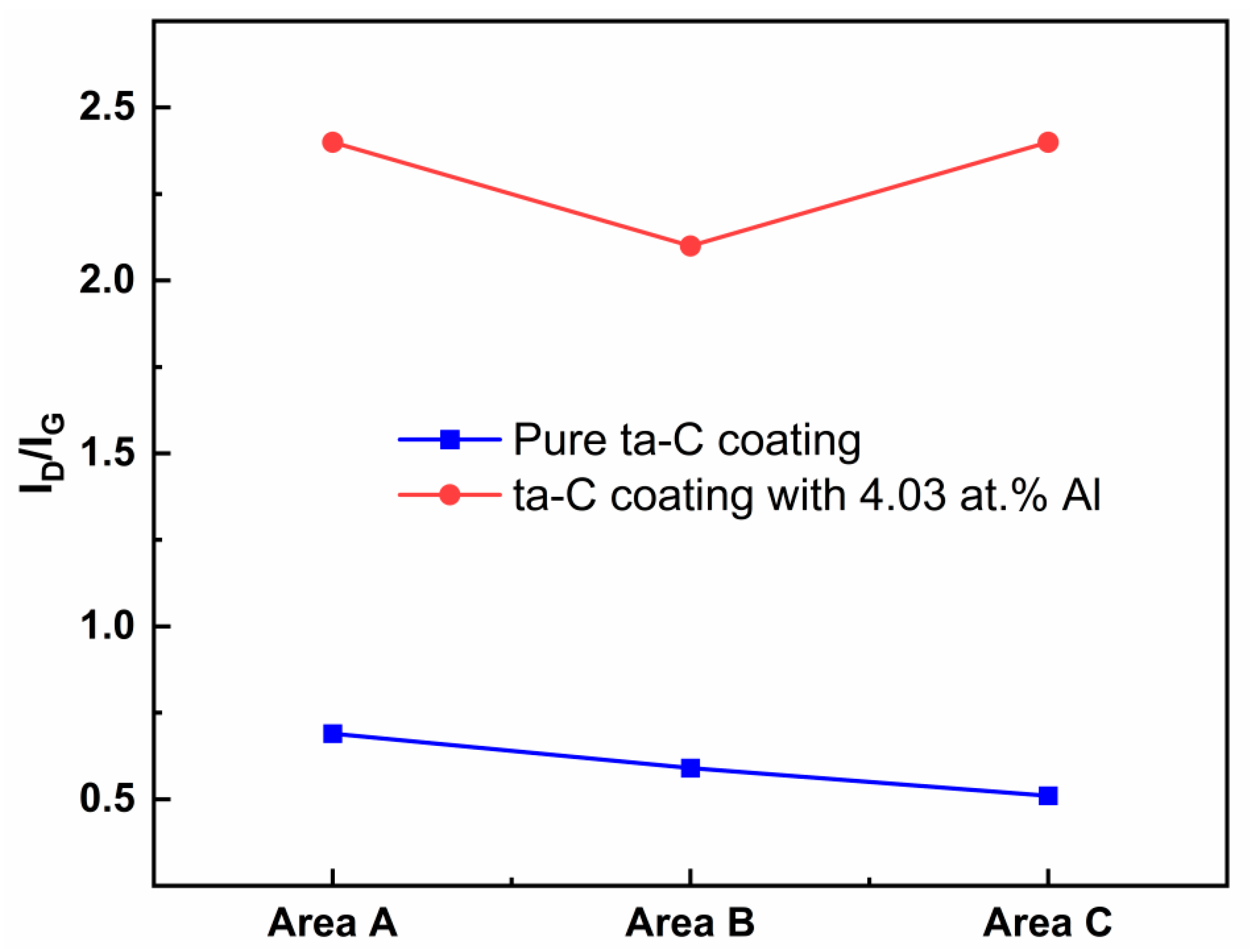
The morphologies of the wear surfaces of the coatings were also analyzed using SEM. Figure 9 shows the typical microtopographies of wear track of pure ta-C coating (Figure 9a,c) and the ta-C:Al coating containing an Al concentration of 4.03 at.% (Figure 9b,d). It is worth noting that the wear track of pure ta-C coating is bordered by numerous wear debris. The detail in the wear track shows that there are many sheet shapes in the wear track (the red arrows in Figure 9c). The Raman spectra was taken on a part of the coating surface without wear (area A), the edge of the wear track (area B) and in the wear track (area C). The ID/IG ratios from the Raman spectra are presented in Figure 10. For the pure ta-C coating, the ID/IG ratios in area A and area B are higher than in area C, implying that the sp3 fraction increases in the wear track (area C). For the ta-C:Al coating with 4.03 at.% Al, however, the ID/IG ratio in area C is slightly higher than these in area A and B, indicating that the sp2 fraction increases in the wear track, while the sp3 fraction increases in the wear edge. It is reported that during the friction process of the hydrogen-free amorphous carbon coating, C-C bonds of carbon atoms are broken and rearranged at the sliding interface, resulting in the graphitization of the carbon matrix structure and the formation of the sp3 C-C bonds [22]. It is clear that the friction process causes the increase the sp3 bonds in pure ta-C coating. However, the Al doping will facilitate the formation of the sp2 clusters. These sheet shapes on the wear tracks might be the graphite-like tribo-layer which has an effect of solid lubrication and thus, reduces friction. It should be noted that the sheet shapes on the wear track show a sharp increase in the size and number for the ta-C:Al coating (Figure 9c,d). The increase in the sheet shapes is mainly due to the incorporation of Al which promotes the segregation of graphitic cluster from the amorphous carbon matrix structure forming graphitic tribo-layer. As a result, the ta-C:Al coating shows a relatively lower friction coefficient compared to the pure ta-C coating (Figure 7b).
4. Conclusions
In this paper, a series of ta-C:Al coatings were deposited by the hybrid technique consisting of cathode arc evaporation equipping with the graphite target and magnetron sputtering equipping with the aluminum target. The doping concentration of Al in the coatings could be adjusted from 0 (pure ta-C) to 24.18 at.% through changing the sputtering power of the Al target from 0 (turn off the sputtering power) to 2.8 kW. The growth rate of the coatings is increasing with the sputtering power of Al. The increases of the growth rate of the ta-C:Al coatings is mainly attributed to the incorporation of Al. The growth structure of the ta-C:Al coating evolves from typical smooth and compact amorphous structure into a coarse and granulose feature. It is found that Al tends to bond to O, forming Al-O and Al-O-C bonds, rather than bonding to C, forming Al-C, when the Al concentration is small. In addition to Al-O and Al-O-C, however, Al will bond to C, forming Al-C bonds, when the Al concentration is high. The Al in small quantities was effective in causing the graphitization of the carbon structure of the coatings, resulting in the increase in the sp2-C cluster size as well as the sp2/sp3 ratio of the ta-C:Al coatings. As the Al concentration increases, the graphitization effect due to the Al doping weakens with increasing Al concentration. The residual stress of the ta-C coatings can be effectively released by the Al doping and decreases with increasing Al concentration in the coatings. The Al doping causes the decrease in the sp3 C-C bond fraction of the ta-C coatings, resulting in the decline of the residual stress. Additionally, the weak ionic bond between Al and C is also helpful to reduce the compressive stress of the carbon-based coatings. The hardness and elastic modulus of the ta-C:Al coatings are mainly related to the carbon structure (sp3 bond fraction), and decrease with the Al concentration. However, the ta-C:Al coatings with an Al concentration ≤ 4.03 at.% still maintain relatively high hardness of about 25 GPa and elastic modulus of about 330 GPa. The Al doping has a significant influence on the tribological performance of the ta-C:Al coatings. Al will facilitate the formation of the graphite-like tribo-layer in the wear track, resulting in the sharp drop of the average friction coefficient of the ta-C:Al coatings. When the Al concentration is high, however, the average friction coefficient and wear rate of the coatings increase with the Al concentration due to the decrease in the hardness. It is believed that there is an optimum concentration of Al where the ta-C:Al coatings possess good comprehensive properties with low residual stress and good mechanical properties and tribological performance.
Author Contributions
Conceptualization, W.D.; methodology, Y.S.; writing—original draft preparation, W.D.; writing—review and editing, W.D. and Q.W.; funding acquisition, W.D. and J.W. All authors have read and agreed to the published version of the manuscript.
Funding
This work was funded by the National Natural Science Foundation of Guangdong province (Grant No: 2021A1515011921) and Dongguan Key Research & Development Program, China (No. 20221200300032).
Institutional Review Board Statement
Not applicable.
Informed Consent Statement
Not applicable.
Data Availability Statement
The data used to support the findings of this study are available from the corresponding author upon request.
Conflicts of Interest
Author Junfeng Wang was employed by the company Guangdong Dtech Technology Co., Ltd. The remaining authors declare that the research was conducted in the absence of any commercial or financial relationships that could be construed as a potential conflict of interest.
References
- Bewilogua, K.; Hofmann, D. History of diamond-like carbon films—From first experiments to worldwide applications. Surf. Coat. Technol. 2014, 242, 214–225. [Google Scholar] [CrossRef]
- Vetter, J. 60 year of DLC coatings: Historical highlights and technical review of cathodic arc processes to synthesize various DLC types, and their evolution for industrial applications. Surf. Coat. Technol. 2014, 257, 213–240. [Google Scholar] [CrossRef]
- Liu, X.; Zhang, H.; Lin, G.; Wang, Z.; Zhang, J.; Shi, H. Advances in deposition of diamond films on cemented carbide and progress of diamond coated cutting tools. Vacuum 2023, 217, 112562. [Google Scholar] [CrossRef]
- Bootkul, D.; Saenphinit, N.; Supsermpol, B.; Aramwit, C.; Intarasiri, S. Synthesis of Ti-doped DLC film on SS304 steels by filtered cathodic vacuum arc (FCVA) technique for tribological improvement. Appl. Surf. Sci. 2014, 310, 293–299. [Google Scholar] [CrossRef]
- Zhou, B.; Piliptsou, D.G.; Jiang, X.; Rogachev, A.V.; Rudenkov, A.S.; Kulesh, E.A. Structure and mechanical properties of Ni and Cr binary doped amorphous carbon coatings deposited by magnetron sputtering and pulse cathodic arc. Thin Solid Films 2020, 701, 137942. [Google Scholar] [CrossRef]
- Zawischa, M.; Weihnacht, V.; Kaspar, J.; Zimmermann, M. Effect of doping elements to hydrogen-free amorphous carbon coatings on structure and mechanical properties with special focus on crack resistance. Mat. Sci. Eng. A-Struct. 2022, 857, 144086. [Google Scholar] [CrossRef]
- Zheng, J.; Lu, Z.; Liu, S.; Ding, J.C.; Ran, S.; Sun, J. Microstructure and tribological behavior in ta-C films prepared by laser-induced filtered cathodic vacuum arc technique: Effect of charge voltage. Vacuum 2024, 219, 112745. [Google Scholar] [CrossRef]
- Yetim, A.F.; Kovaci, H.; Kasapoglu, A.E.; Bozkurt, Y.B.; Celik, A. Influences of Ti, Al and V metal doping on the structural, mechanical and tribological properties of DLC films. Diamond Relat. Mater. 2021, 120, 108639. [Google Scholar] [CrossRef]
- Choi, J.H.; Lee, S.C.; Lee, K.R. A first-principles study on the bond characteristics in carbon containing Mo, Ag, or Al impurity atoms. Carbon 2008, 46, 185. [Google Scholar] [CrossRef]
- Dai, W.; Wang, A. Deposition and properties of Al-containing diamond-like carbon films by a hybrid ion beam sources. J. Alloy. Compd. 2011, 509, 4626–4631. [Google Scholar] [CrossRef]
- Peckus, D.; Meskinis, S.; Vasiliauskas, A.; Rajackaite, E.; Andrulevicius, M.; Kopustinskas, V.; Tamulevicius, S. Structure and optical properties of diamond like carbon films containing aluminium and alumina. Appl. Surf. Sci. 2020, 529, 147040. [Google Scholar] [CrossRef]
- Guo, C.Q.; Li, H.Q.; Peng, Y.L.; Dai, M.J.; Lin, S.S.; Shi, Q.; Wei, C.B. Residual stress and tribological behavior of hydrogen-free Al-DLC films prepared by HiPIMS under different bias voltage. Surf. Coat. Technol. 2022, 445, 128713. [Google Scholar] [CrossRef]
- Ding, J.C.; Cai, H.; Zhang, Z.; Mei, H.; Zheng, J.; Zhang, T.F. Microstructure evolution and mechanical properties of Al doped ta-C films prepared by filtered cathodic vacuum arc. Vacuum 2023, 216, 112412. [Google Scholar] [CrossRef]
- Robertson, J. Diamond-Like Amorphous Carbon. Mat. Sci. Eng. R. 2002, 37, 129–281. [Google Scholar] [CrossRef]
- Stoney, G.G. The tension of metallic films deposited by electrolysis. Proc. R. Soc. London Ser. A 1909, 82, 172. [Google Scholar]
- Dai, W.; Ke, P.; Wang, A. Influence of bias voltage on microstructure and properties of Al-containing diamond-like carbon films deposited by a hybrid ion beam system. Surf. Coat. Technol. 2013, 229, 217–221. [Google Scholar] [CrossRef]
- Ferrari, A.C.; Robertson, J. Interpretation of Raman spectra of disordered and amorphous carbon. Phys. Rev. B 2000, 61, 14095. [Google Scholar] [CrossRef]
- Casiraghi, C.; Ferrari, A.C.; Robertson, J. Raman spectroscopy of hydrogenated amorphous carbons. Phys. Rev. B 2005, 72, 085401.1–085401.14. [Google Scholar] [CrossRef]
- Kametani, N.; Nakamura, M.; Yashiro, K.; Takaki, T. Investigating residual stress evolution in the deposition process of diamond-like carbon film through molecular dynamics. Comp. Mater. Sci. 2022, 209, 111420. [Google Scholar] [CrossRef]
- Li, X.; Guo, P.; Sun, L.; Zuo, X.; Zhang, D.; Ke, P.; Wang, A. Ti/Al co-doping induced residual stress reduction and bond structure evolution of amorphous carbon films: An experimental and ab initio study. Carbon 2017, 111, 467–475. [Google Scholar] [CrossRef]
- Ni, W.; Cheng, Y.T.; Weiner, A.M.; Perry, T.A. Tribological behavior of diamond-like-carbon (DLC) coatings against aluminum alloys at elevated temperatures. Surf. Coat. Technol. 2006, 201, 3229–3234. [Google Scholar] [CrossRef]
- Müller, I.C.; Sharp, J.; Rainforth, W.M.; Hovsepian, P.; Ehiasarian, A. Tribological response and characterization of Mo–W doped DLCcoating. Wear 2017, 376–377, 1622–1629. [Google Scholar] [CrossRef]
Figure 1.
The cross-section morphology of the ta-C:Al coatings with different sputtering powers of Al target: (a) 0 kW (pure ta-C), (b) 0.23 kW, (c) 0.5 kW, (d) 0.8 kW, (e) 1.2 kW and (f) 2.8 kW.
Figure 1.
The cross-section morphology of the ta-C:Al coatings with different sputtering powers of Al target: (a) 0 kW (pure ta-C), (b) 0.23 kW, (c) 0.5 kW, (d) 0.8 kW, (e) 1.2 kW and (f) 2.8 kW.
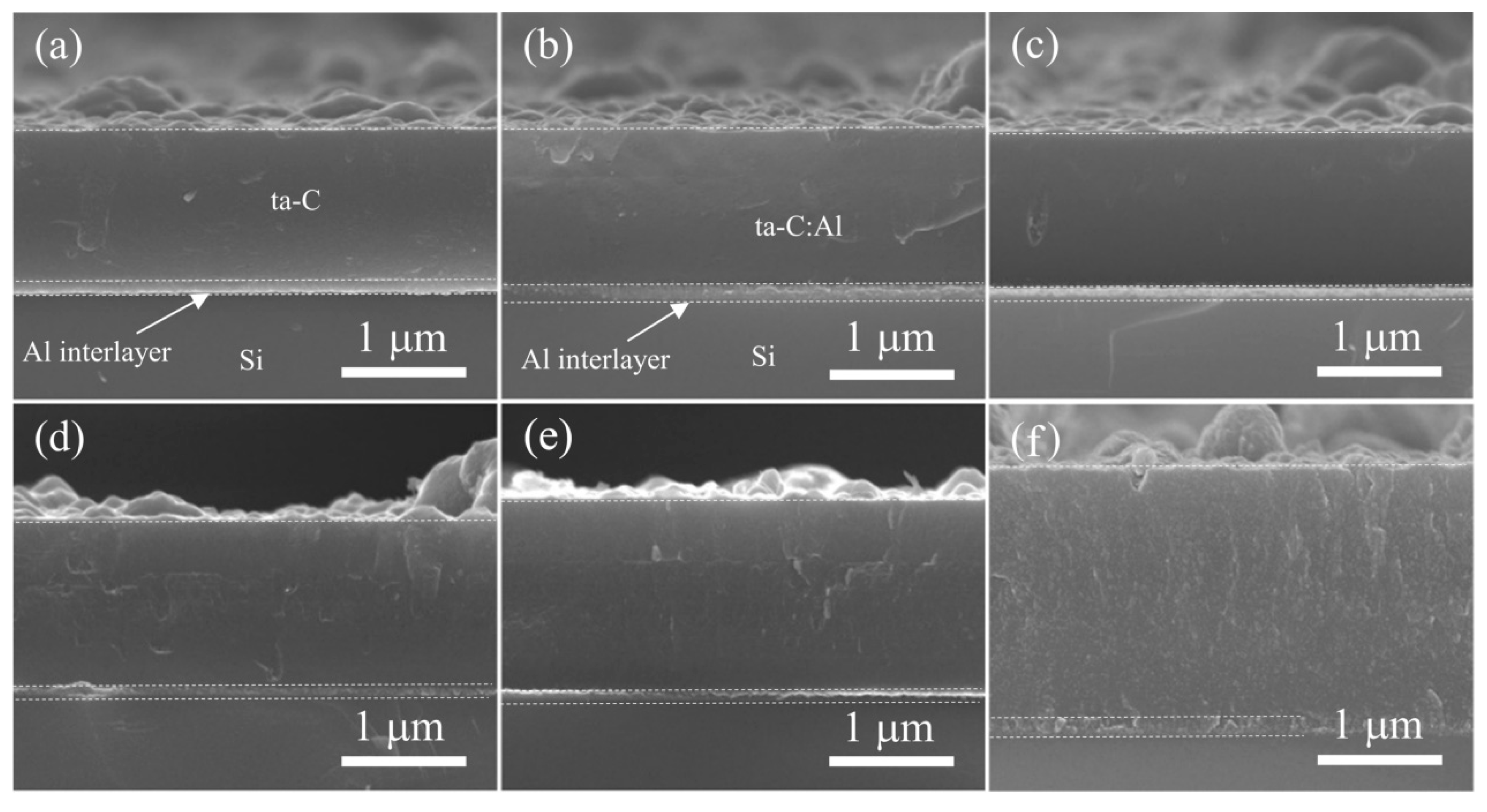
Figure 2.
The evolution of the Al, C and O of the ta-C:Al coatings as a function of the sputtering power of the Al target.
Figure 2.
The evolution of the Al, C and O of the ta-C:Al coatings as a function of the sputtering power of the Al target.
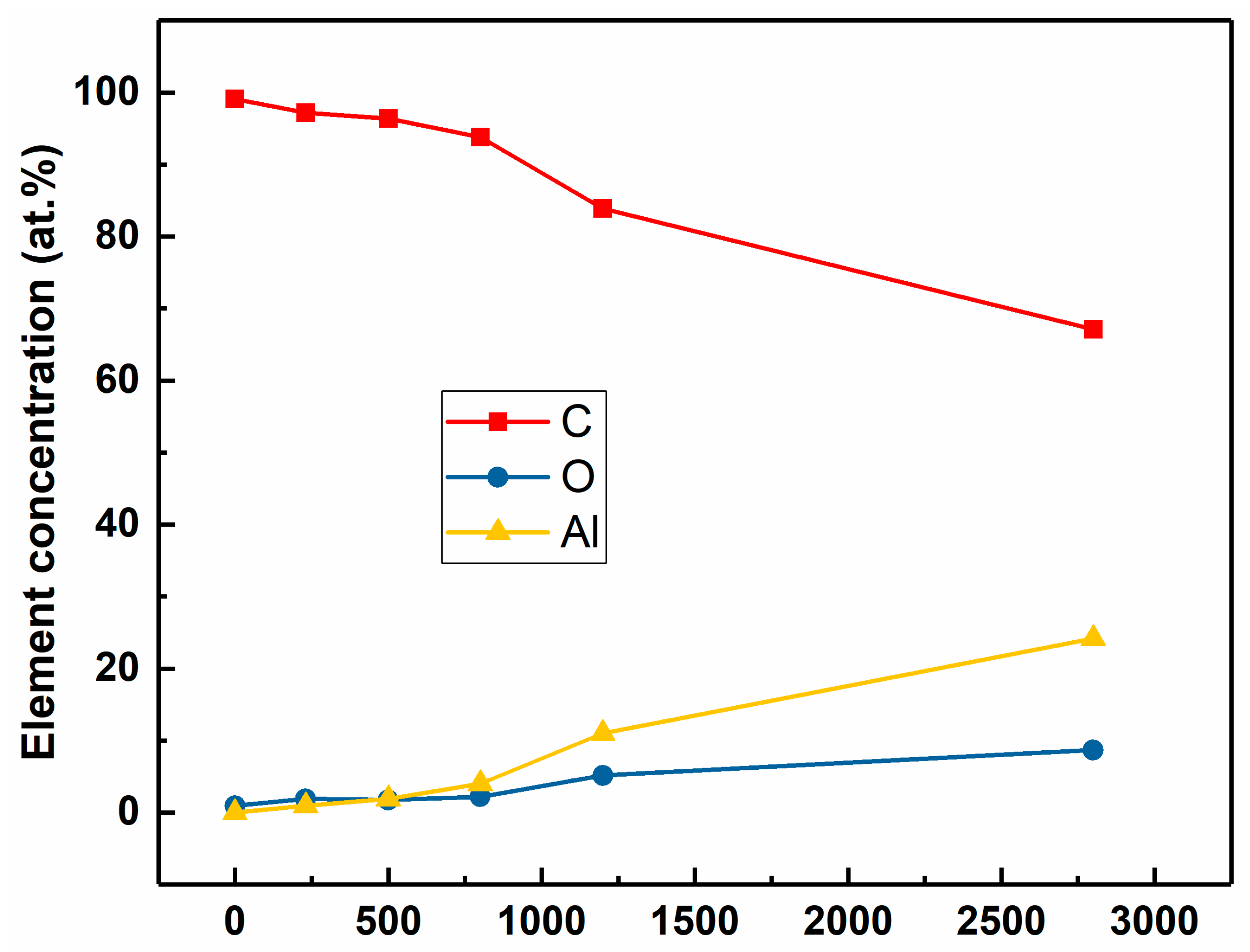
Figure 3.
The typical high-resolution C1s and Al2p core level XSP spectra of the ta-C:Al coatings with different Al concentrations: (a,d) pure ta-C, (b,e) 1.87 at.%, and (c,f) 24.18 at.%.
Figure 3.
The typical high-resolution C1s and Al2p core level XSP spectra of the ta-C:Al coatings with different Al concentrations: (a,d) pure ta-C, (b,e) 1.87 at.%, and (c,f) 24.18 at.%.
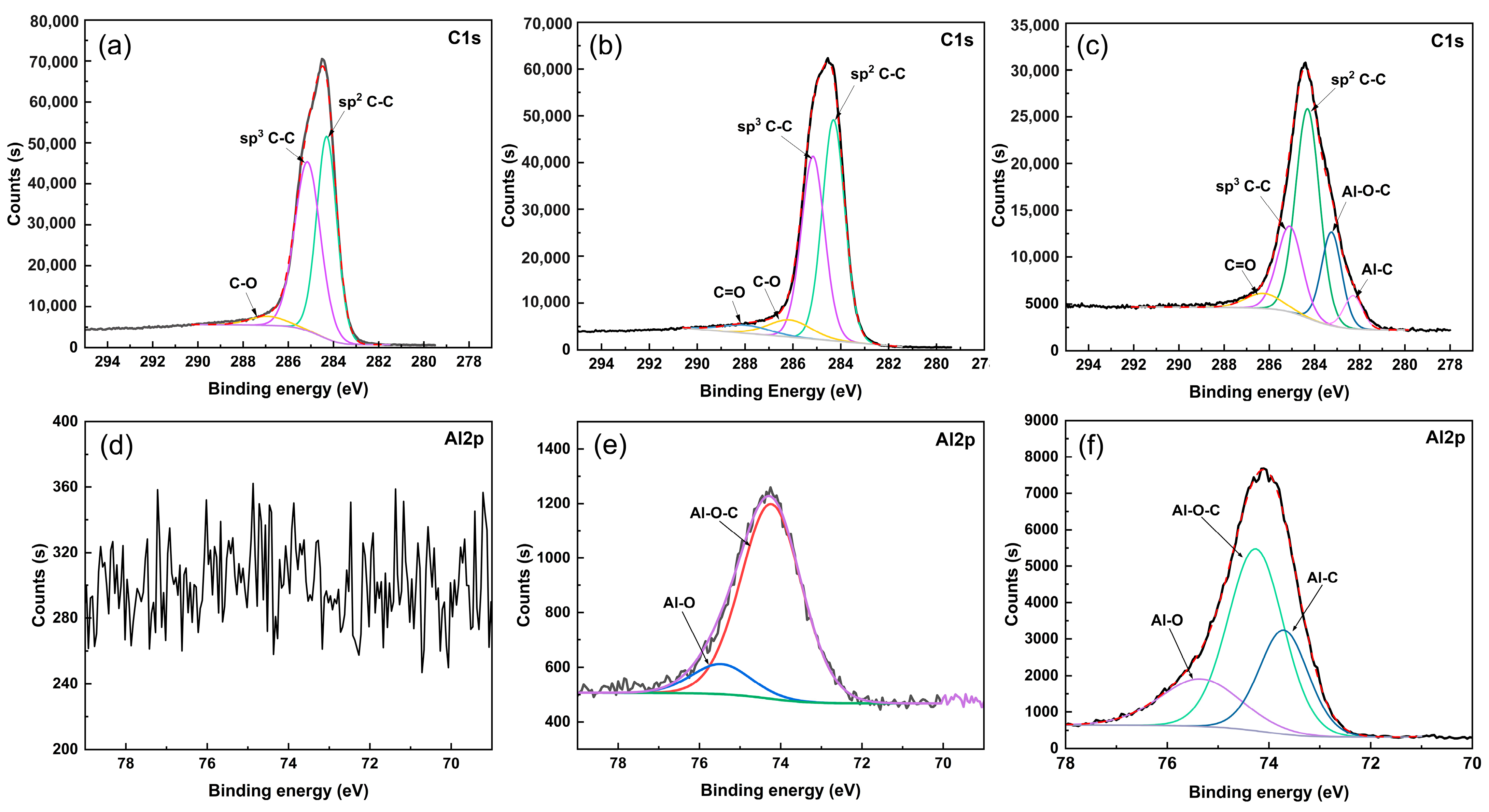
Figure 4.
(a) Raman spectra, (b) the corresponding G-peak position and the intensity ratio of the D-peak to G-peak (ID/IG), and (c) the GFWHM (full width at half maximum of the G peak) of the ta-C:Al coatings with containing different Al concentrations.
Figure 4.
(a) Raman spectra, (b) the corresponding G-peak position and the intensity ratio of the D-peak to G-peak (ID/IG), and (c) the GFWHM (full width at half maximum of the G peak) of the ta-C:Al coatings with containing different Al concentrations.
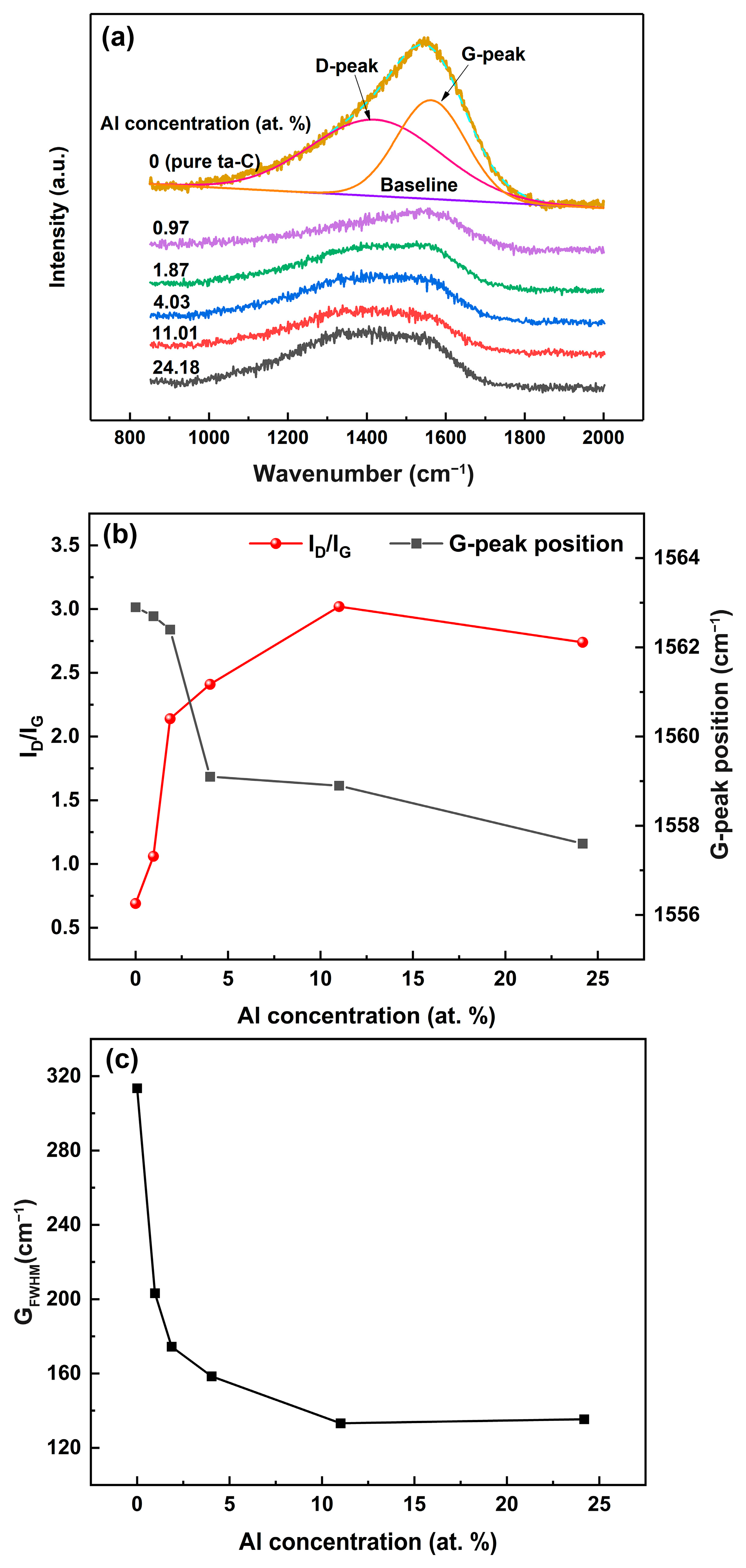
Figure 5.
The compressive stresses of the ta-C:Al coatings as a function of the Al concentration.

Figure 6.
The hardness and elastic modulus of the ta-C:Al coatings as a function of the Al concentration.
Figure 6.
The hardness and elastic modulus of the ta-C:Al coatings as a function of the Al concentration.
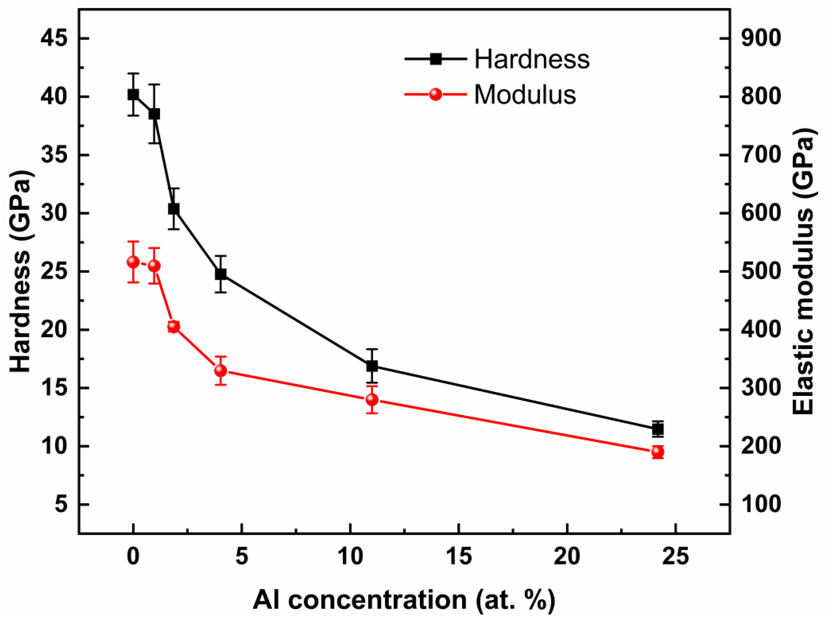
Figure 7.
(a) the dynamic curves of the friction coefficient of the coatings containing various Al concentration as a function of the sliding cycles; (b) the corresponding average friction coefficients and wear rate of the ta-C:Al coatings as a function of the Al concentration.
Figure 7.
(a) the dynamic curves of the friction coefficient of the coatings containing various Al concentration as a function of the sliding cycles; (b) the corresponding average friction coefficients and wear rate of the ta-C:Al coatings as a function of the Al concentration.
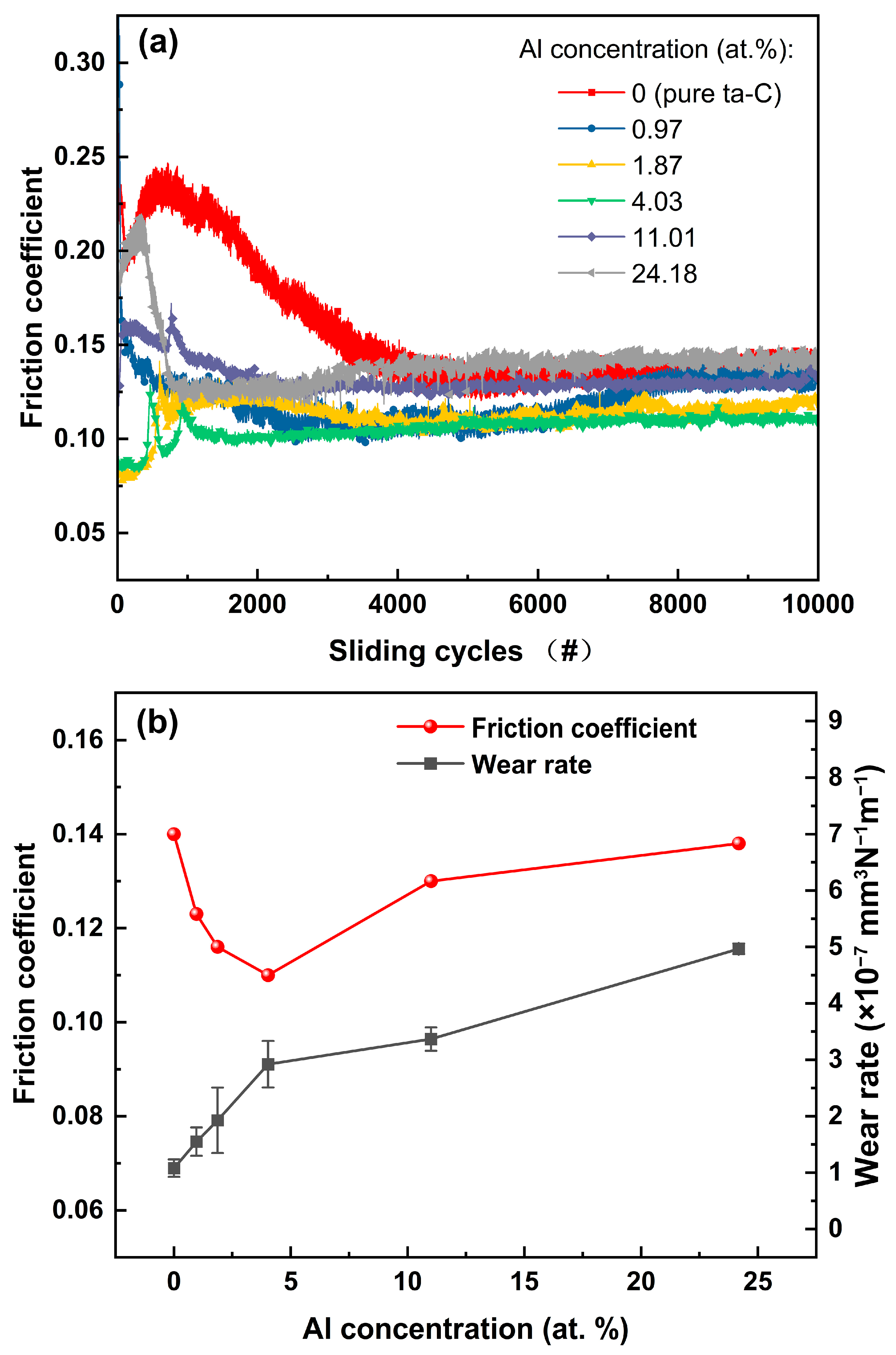
Figure 8.
The morphology and the corresponding the cross-section profiles of the wear tracks of the ta-C:Al coatings with different Al concentrations: (a) pure ta-C, (b) 0.97 at.%, (c) 1.87 at.%, (d) 4.03 at.%, (e) 11.01 at.% and (f) 24.18 at.%.
Figure 8.
The morphology and the corresponding the cross-section profiles of the wear tracks of the ta-C:Al coatings with different Al concentrations: (a) pure ta-C, (b) 0.97 at.%, (c) 1.87 at.%, (d) 4.03 at.%, (e) 11.01 at.% and (f) 24.18 at.%.
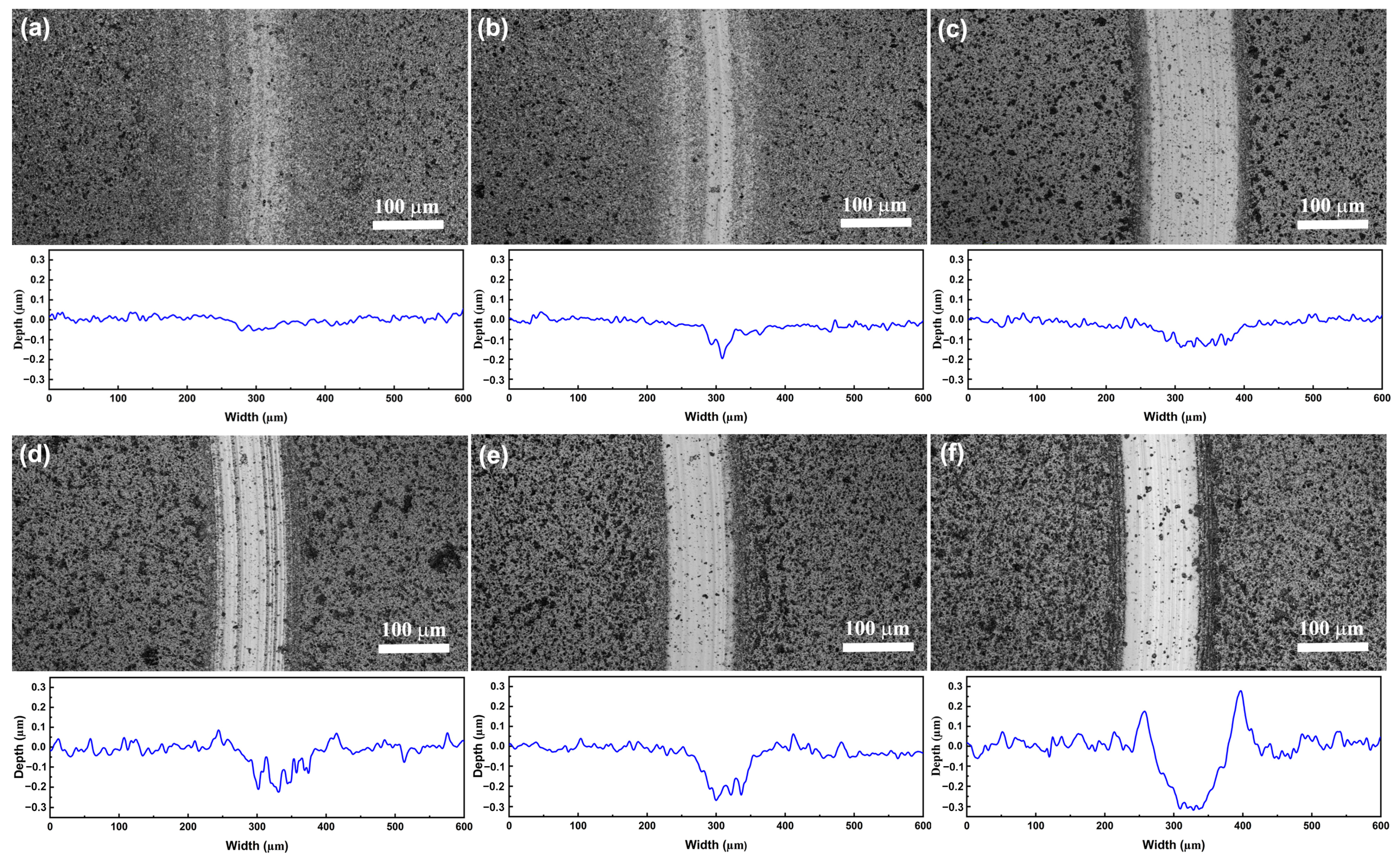
Figure 9.
Typical microtopography of the wear tracks of the pure ta-C coating (a) and the ta-C:Al coating containing the Al concentration of 4.03 at.% (b). (c,d) are the details of the (a,b), respectively.
Figure 9.
Typical microtopography of the wear tracks of the pure ta-C coating (a) and the ta-C:Al coating containing the Al concentration of 4.03 at.% (b). (c,d) are the details of the (a,b), respectively.
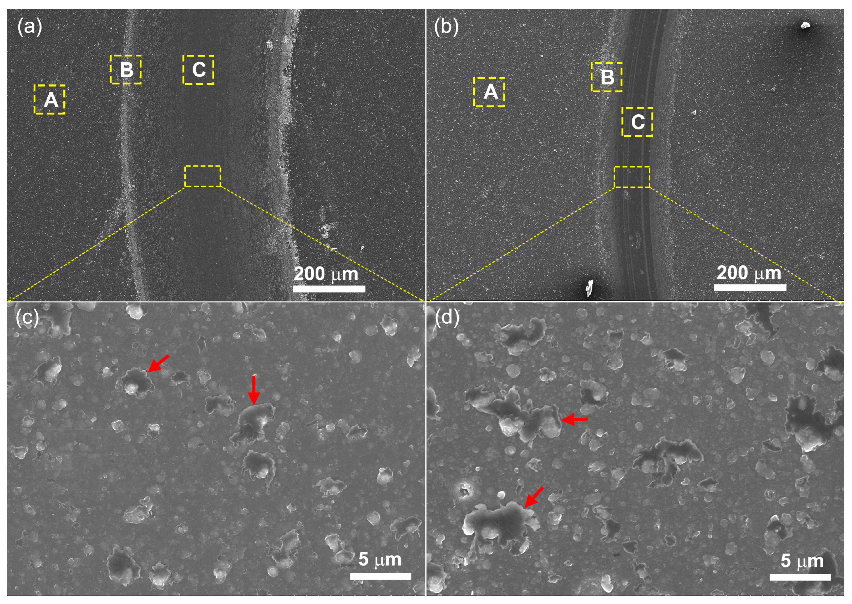
Figure 10.
The ID/IG ratio of the Raman spectra taken on area A (the part of the coatings surface without wear), area B (the edge of the wear track) and area C (in the wear track) in Figure 9.
Figure 10.
The ID/IG ratio of the Raman spectra taken on area A (the part of the coatings surface without wear), area B (the edge of the wear track) and area C (in the wear track) in Figure 9.
Disclaimer/Publisher’s Note: The statements, opinions and data contained in all publications are solely those of the individual author(s) and contributor(s) and not of MDPI and/or the editor(s). MDPI and/or the editor(s) disclaim responsibility for any injury to people or property resulting from any ideas, methods, instructions or products referred to in the content. |
© 2024 by the authors. Licensee MDPI, Basel, Switzerland. This article is an open access article distributed under the terms and conditions of the Creative Commons Attribution (CC BY) license (https://creativecommons.org/licenses/by/4.0/).
Share and Cite
MDPI and ACS Style
Dai, W.; Shi, Y.; Wang, Q.; Wang, J. Tetrahedral Amorphous Carbon Coatings with Al Incorporation Deposited by a Hybrid Technique of Sputtering and Arc Evaporation. Coatings 2024, 14, 142. https://doi.org/10.3390/coatings14010142
AMA Style
Dai W, Shi Y, Wang Q, Wang J. Tetrahedral Amorphous Carbon Coatings with Al Incorporation Deposited by a Hybrid Technique of Sputtering and Arc Evaporation. Coatings. 2024; 14(1):142. https://doi.org/10.3390/coatings14010142
Chicago/Turabian StyleDai, Wei, Yunzhan Shi, Qimin Wang, and Junfeng Wang. 2024. "Tetrahedral Amorphous Carbon Coatings with Al Incorporation Deposited by a Hybrid Technique of Sputtering and Arc Evaporation" Coatings 14, no. 1: 142. https://doi.org/10.3390/coatings14010142
Note that from the first issue of 2016, this journal uses article numbers instead of page numbers. See further details here.