
Long-Distance Freezing Design and Construction Based on Monitoring Analysis of Subway Connection Aisle


1
School of Urban Construction, Wuhan City College, Huangjia Dawan, Wuhan 430075, China
2
Wuhan United Investments and Properties Co., Ltd., 399 Wenhua Avenue, Wuhan 430212, China
3
School of Civil Engineering, Central South University, 22 Shaoshan Road, Changsha 410075, China
4
South China Company, China Construction Second Engineering Bureau Ltd., Shenzhen 518048, China
5
National Engineering Research Center for High Speed Railway Construction, Changsha 410075, China
*
Author to whom correspondence should be addressed.
Coatings 2024, 14(3), 355; https://doi.org/10.3390/coatings14030355
Submission received: 1 February 2024
/
Revised: 8 March 2024
/
Accepted: 12 March 2024
/
Published: 18 March 2024
(This article belongs to the Special Issue Green and Low-Carbon Buildings: Materials, Technology and Processes and Techniques)
Abstract
:In the context of a main road area with significant traffic flow, posing challenges to constructing the freezing station on the ground, an innovative proposal suggests situating the freezing station at the station. This approach aims to facilitate construction at the same time for the connection aisle, tunneling, and track laying, thereby reducing the construction period; however, this will lead to a corresponding increase in the freezing pipeline distance. The theoretical analysis, numerical analysis, and integration with engineering practices were employed to examine the essential aspects and key technologies in the long-distance freezing design and construction, including the freezing hole construction, thermal insulation method of brine pipelines and tunnel segments, and technique program to retain the brine pressure and flow discharge, as well as the method to reduce the interplay of cross-construction. The validity of the construction program for the long-distance frozen excavation was finally evaluated based on onsite monitoring and theoretical analysis. The results show that the temperature of the brine in both the delivery and return pipelines first decreases linearly and then stabilizes gradually with freezing time, and the temperature difference is between 1 °C and 1.5 °C at the later freezing period. The temperature variation of the frozen wall is similar to that of brine in the delivery and return pipelines, and there is a good correlation between them. After the frozen wall encloses, the internal pressure of the frozen wall increases quickly, which can be effectively reduced to prevent wall cracking and breakage by regulating the pressure relief holes. The above theoretical analysis result shows that the average temperature of the frozen wall should be less than −9.7 °C when the designed thickness of the frozen wall is 2.2 m. The monitoring data indicates that the average temperature of the frozen wall reaches −13.9 °C, which satisfies the design requirement. The design and construction technology of long-distance freezing enhance the construction of the subway connection aisle. The novel method deviates from the conventional practice of establishing freezing stations within tunnels and offers valuable insight and guidance for comparable projects.
1. Introduction
In recent years, with the rapid development of urbanization construction, more and more underground projects are facing the problem of crossing water-rich and weak strata. The reliable treatment method is necessary for these projects; otherwise, it is easy to cause water and sand gushing, pipe gallery deformation, and other engineering accidents, which will bring great difficulty and risk to the engineering construction [1,2,3]. Since artificial ground freezing (AGF) was first used by Sweden to construct a tunnel in 1886, the AGF method was gradually used to construct underground engineering projects [4], which has also been widely used in fields of subways [5], tunnels [6], mining engineering [7], deep excavations [8], drilling [9], etc. The AGF method has gradually become one of the main methods of urban underground engineering construction due to its advantages of safety and reliability of freezing and reinforcement, good water sealing effect, green environmental protection, and low pollution [10,11,12], especially in the construction and application of urban subway connection aisles.
The freezing phenomenon occurs at the level of the material’s structure. When the material’s surface experiences negative temperatures, the liquid water in larger pores freezes first, while that in smaller pores requires a lower temperature due to the lower Gibbs free energy [13]. The freezing process in the subway connection aisle depends on the flow of freezing liquid in the pipeline. A higher flow rate of the freezing brine in the pipeline brings the temperature of the pipeline’s working surface closer to the freezing station’s set temperature, leading to the freezing of soil material. The freezing effect correlates with the material’s constituent components and structure [14,15]. Ultimately, the freezing soil forms a curtain with specific strength.
At present, the research on the application of artificial ground freezing in subway connection aisles mainly focuses on these engineering projects, as shown in Table 1. These studies primarily concentrate on the analysis of the temperature field and freezing process and are limited to short freezing pipelines. However, there is a deficiency in thorough and comprehensive research on freezing design methods and technical measures for long-distance freezing construction. On the one hand, long-distance temperature control incurs higher costs and poses operational challenges. On the other hand, the construction technology for long-distance temperature control is not yet mature. Nevertheless, this technology holds significant practical importance for enhancing work efficiency and deserves to be studied.
Traditionally, in the construction of subway connection aisles, the freezing station is placed near the connection aisle within the tunnel after it has been excavated. This proximity minimizes the distance for delivering low-temperature brine during the freezing process [24,25]. However, the synchronized construction of connection aisles, tunneling, and track laying was inevitably necessary in order to shorten the construction period and achieve subway connectivity as soon as possible, or the freezing station sometimes cannot be laid out near the connection aisle in the tunnel due to restrictions of the geology and surrounding environment. In addition, because the ground above the subway connection aisle was usually the urban trunk road with a large traffic flow, there was no feasible condition to lay out the freezing station on the ground. Therefore, the freezing station can only be laid out at the subway station. Thus, it is of theoretical significance and practical guidance to study frozen reinforcement and construction by transporting low-temperature brine through the ultra-long brine pipeline.
The purpose of this study is to investigate the impact of long-distance freezing design and construction, offering a novel construction approach for the subway connection channel. The key factors influencing the process include the freezing station’s location, temperature control, soil strength, and construction technology. Combined with on-site monitoring and theoretical analysis, the effectiveness of the long-distance freezing design and construction is assessed. The findings can offer references and guidance for the design, construction, and monitoring of similar engineering projects.
2. Theoretical Background
2.1. Project Profile
The total length of Wuhan Subway Line 21 was 33.7 km in total, and the connection aisle between Houhu Avenue Station and Happiness Bay Station was reinforced by artificial ground freezing, and the length of the transportation pipeline of brine was larger than 1 km. This ultra-long connection aisle was located on the fine silty sand ground, which belongs to the typical first-level land of the Yangtze River, and the soil layer was homogeneous. The groundwater level was shallow, and there was no salinity in both the soil and the groundwater. The stratum was water-rich and relatively weak. Therefore, the AGF method was a reliable choice for soil reinforcement and treatment of the connection aisle.
2.2. Long-Distance Freezing Design of the Connection Aisle
2.2.1. Basic Principles of Freezing Reinforcement Design
Based on the requirements of long-distance freezing construction in this project, the following basic principles for freezing reinforcement design were proposed to control the influence of drilling of freezing holes, stratum frost heave, and thawing settlement on tunnels and urban ground.
- (1)
- The near-horizontal or inclined holes were used when drilling the freezing holes in the tunnel according to the structure of the connection aisle. Each drilling hole was equipped with an orifice pipe, and an orifice sealing device was installed to prevent the gushing of a large amount of mud during drilling. After each drilling, the volume of the outflow from the hole should be calculated in time, and the holes should be grouted immediately, combining with changes in monitoring data of the surface subsidence.
- (2)
- The thickness and strength of the frozen wall should meet the requirements of connection aisle excavation, especially the thickness of the frozen wall at the bell mouth, and in the meantime, the frozen wall should be completely bonded to the tunnel segments. The freezing and excavation should cooperate, and the excavation construction process should be adjusted in time based on the deformation of the frozen wall after excavation.
- (3)
- In order to reduce the influence of frost heave on subway tunnels, cold pipes and insulation layers were laid on the left and right tunnel segments near the bell mouth. The freezing speed was increased by reducing the distance between the freezing hole and the opposite tunnel segment and adopting a low brine temperature and large brine flow. In addition, the influence of soil frost heaves on tunnels was also reduced by laying out pressure relief holes in appropriate places.
- (4)
- The formation process and condition of the frozen wall were monitored through temperature measurement holes and pressure relief holes, especially the cementation condition between the frozen wall and opposite tunnel segments.
- (5)
- The grouting holes were embedded in the bottom plate, both sides, and top of the connection aisle, as well as the concrete of the pump house. The grouting holes were drilled in the tunnel segments for the convenience of grouting if necessary to prevent settlement and deformation of the ground tunnel and connection aisle. The temperature and settlement deformation of the frozen stratum and the deformation of the tunnel were monitored to guide the construction of the connection aisle.
- (6)
- A natural defrost method for thawing settlement grouting was used to control the differential settlement of soil and reduce the detrimental effects of freeze-thaw.
2.2.2. Key Points of Freezing Reinforcement Design
According to the survey, design, and engineering construction safety data of this project, the freezing reinforcement technology and construction requirements of this subway connection aisle were as follows:
- (1)
- The design indexes of uniaxial compressive strength, bending strength, and shear strength of frozen soil (−10 °C) were 4.0 MPa, 1.8 MPa, and 1.5 MPa, respectively.
- (2)
- The frozen wall thickness was 2.2 m, among which the thickness of the bell mouth was 1.9 m, and the average temperature of the frozen wall was lower than −10 °C.
- (3)
- The freezing hole should be sealed after completion of the freezing construction, and the strength of the sealing concrete should not be lower than that of the segment.
- (4)
- At the openings of the connection aisle, the pre-stressed tunnel bracket should be laid out uniformly at the unopened part of the opening ring of the tunnel segment to reduce the adverse impact of the excavation construction on the connection aisle, and an emergency safety door should be installed above the tunnel portal on the excavation side.
2.2.3. Main Design Parameters for Freezing Reinforcement
The freezing station for this project was located at the middle plate of the station, approximately 1.1 km away from the connection aisle. In order to ensure the frozen wall reaches the design thickness, the layout of the freezing holes around the connection aisle included three angles, that is, upward, horizontal, and downward, according to the above basic principles and key points of the freezing wall design and the structure of the connection aisle. In addition, the holes were laid out separately in two tunnels, namely, the main freezing holes, temperature measurement holes, and pressure relief holes, on both sides of the tunnel. The double-row linear holes were used in the upper and bottom of the tunnel, and single-row linear holes were used on both sides. The holes basically penetrated the soil between the tunnels in the depth direction to strengthen the freezing effect. In order to ensure the strength of the frozen soil and the excavation safety of the connection aisle, the connection aisle and pump house were closed to ensure that the freezing pipe could not be excavated in the pump house.
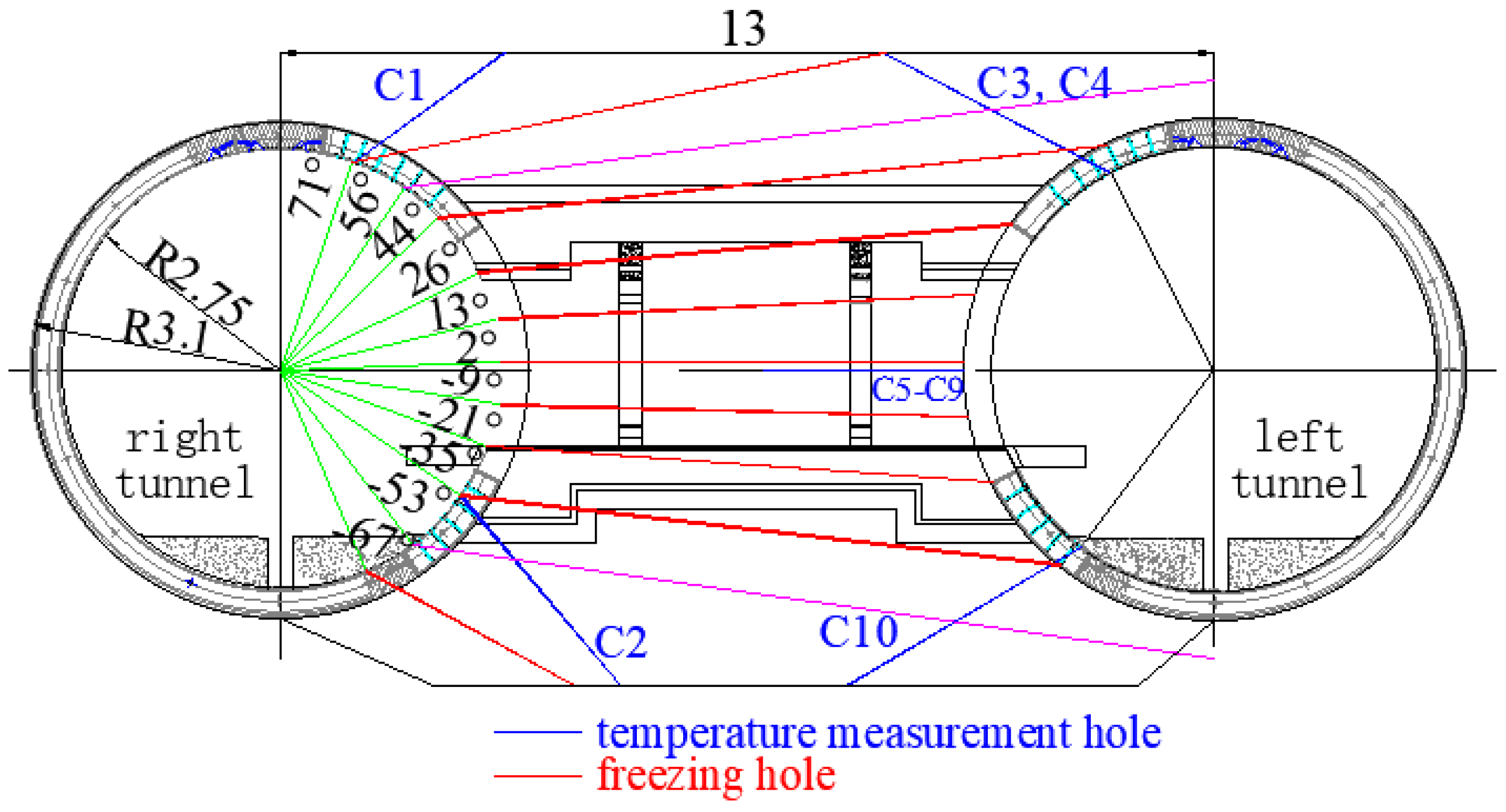
The cross-section of the frozen wall of the typical connection aisle of this project is shown in Figure 1. A total of 45 freezing holes (including 2 through holes), 10 temperature measurement holes, and 4 pressure relief holes were arranged inside the frozen wall. The pressure relief was measured using the sensor (DMTY micro earth pressure cell) produced by Nanjing Danmo Electronic Technology Co. Ltd. in Nanjing, China, and the measuring range of the sensor was 2.0 MPa with a precision of 0.5% relative to the range. The designed thickness of the freezing wall was no less than 2.2 m, and the average temperature was below −10 °C. The position of each hole can be observed from both the cross-sectional drawing (Figure 1) and the sectional view (Figure 2).
According to the design points of the frozen wall, the structure of the connection aisle, and the pre-test of the stratum frozen, the main design parameters for the typical freezing construction of the connection aisle in this project were determined, as shown in Table 2. The values of three parameters of frozen soil strength were selected based on the criterion, and the three parameters of frozen soil strength must be satisfied for employing the artificial ground freezing method in the construction of the connection aisle in China [26]. The thickness of the frozen wall at the bell mouth was less than 1.9 m. The active frozen time was less than 55 d and can be extended appropriately according to the formation status of the frozen wall. The minimum brine temperature was −28 °C, and the brine temperature at 7 d should be smaller than −18 °C.
2.2.4. Refrigeration System Design
- (1)
- The calculation of the heat absorption capacity of the frozen pipes and calandria [27] is performed using the following formula:where —total heat absorption capacity of the frozen pipes (kJ/h), A—total surface area of the freezer (m2), q—the heat absorption coefficient of the frozen pipes, which was 1047–1172 (kJ/m2h). In this project, = 3.65 × 10⁴ kcal/h.
- (2)
- The calculation of the refrigeration capacity of frozen stations [27] is performed using the following formula:where Qz—refrigeration capacity of frozen station (kJ/h), m—cooling loss coefficient with a value of 1.1–2.
Because the frozen station was placed inside the station in this project, the transportation pipeline of brine was extended, which resulted in a relatively large cooling loss. The maximum extension was assumed to be 600 m (back and forth), and m was set as 2.0, so Qz can be calculated as follows:
The type and quantity of refrigeration equipment were determined by the refrigeration capacity of the frozen station and the condensation temperature and evaporation temperature of the refrigerant circulation system. Therefore, two pieces of refrigeration equipment (model: JYSLG16F) were selected for this project: one for use and the other for backup.
- (3)
- Brine circulation refrigeration system:
The brine circulation refrigeration system is shown in Figure 3.
Flow rate of brine: the flow rate of brine in the supply pipe was 0.6~1.5 m/s, and that in the main pipe and the distribution pipe was 1.5~2.0 m/s.
Calcium chloride solution: The freezing point of calcium chloride aqueous solution should be 8–10 °C lower than the designed brine temperature, and the specific density of calcium chloride aqueous solution should not exceed 1.27.
Cooling water: The operating temperature of the screw compressors should be lower than 28 °C. The pH value of cooling water should be 6.5–8.5. The hardness of carbonate was 5–7 (mg equivalent/L), and the turbidity was less than 50 mg/L. A cooling tower made of glass fiber-reinforced plastics with a water pump flow of 50–200 m3/h was recommended.
3. Research Study
3.1. Force Analysis of the Frozen Wall
The numerical simulation of the frozen walls at normal cross-sections of the connection aisle was performed using MIDAS GTS NX software. The results are shown in Figure 4, Figure 5 and Figure 6.
It can be found through simulation that the unfavorable section of the frozen wall on the normal section of the connection aisle is located at the corner of the wall and the middle of the bottom plate. The calculated internal force values at these sections are shown in Table 3, and the stress and safety coefficient at the most adverse section of the frozen wall are shown in Table 4, which meet the freezing strength requirements.
3.2. Critical Technologies for Long Distance Freezing Construction of Connection Aisle
3.2.1. Construction of the Freezing Hole
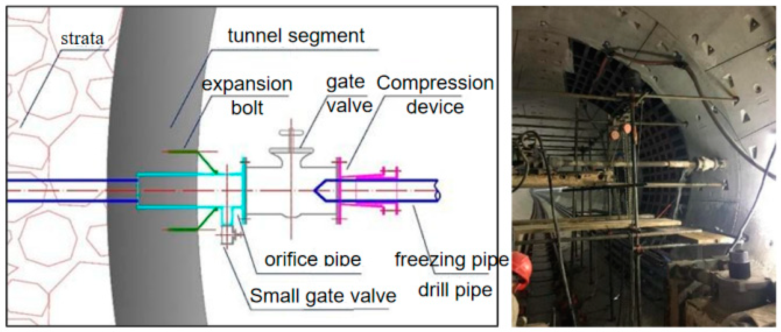
A diamond drill was used to drill holes according to the design angle. The orifice was installed on the gate valve with a sealing gasket between them, as shown in Figure 7. The drilling construction of the freezing hole was carried out through the orifice position by using the freezing pipe as the drilling pipe, as well as the installation of the freezing stations and pipelines, as shown in Figure 8.
3.2.2. Refrigeration Guarantee Methods
- (1)
- Heat dissipation at a frozen station
The frozen station was set in the station, so the heat generated by the cooling tower cannot dissipate in time due to the poor air circulation in the station, which often affects the normal work of the refrigerating battery, resulting in the fact that the dropping speed of the brine temperature cannot meet the design requirements. In order to ensure that the frozen station can cool the brine smoothly to the design requirements, the frozen station was set in the ventilated and cooling place of the center plate of the station, and a moisture-proof layer was installed at the bottom of the refrigerating battery. Meanwhile, a bearing-type fan was used to ensure the dissipation of heat generated by the refrigerating battery in time. In addition, the cooling water of the frozen station was updated in time according to the design requirements to ensure that the cooling water temperature was less than 25 °C.
- (2)
- Heat insulation for brine pipes and segments
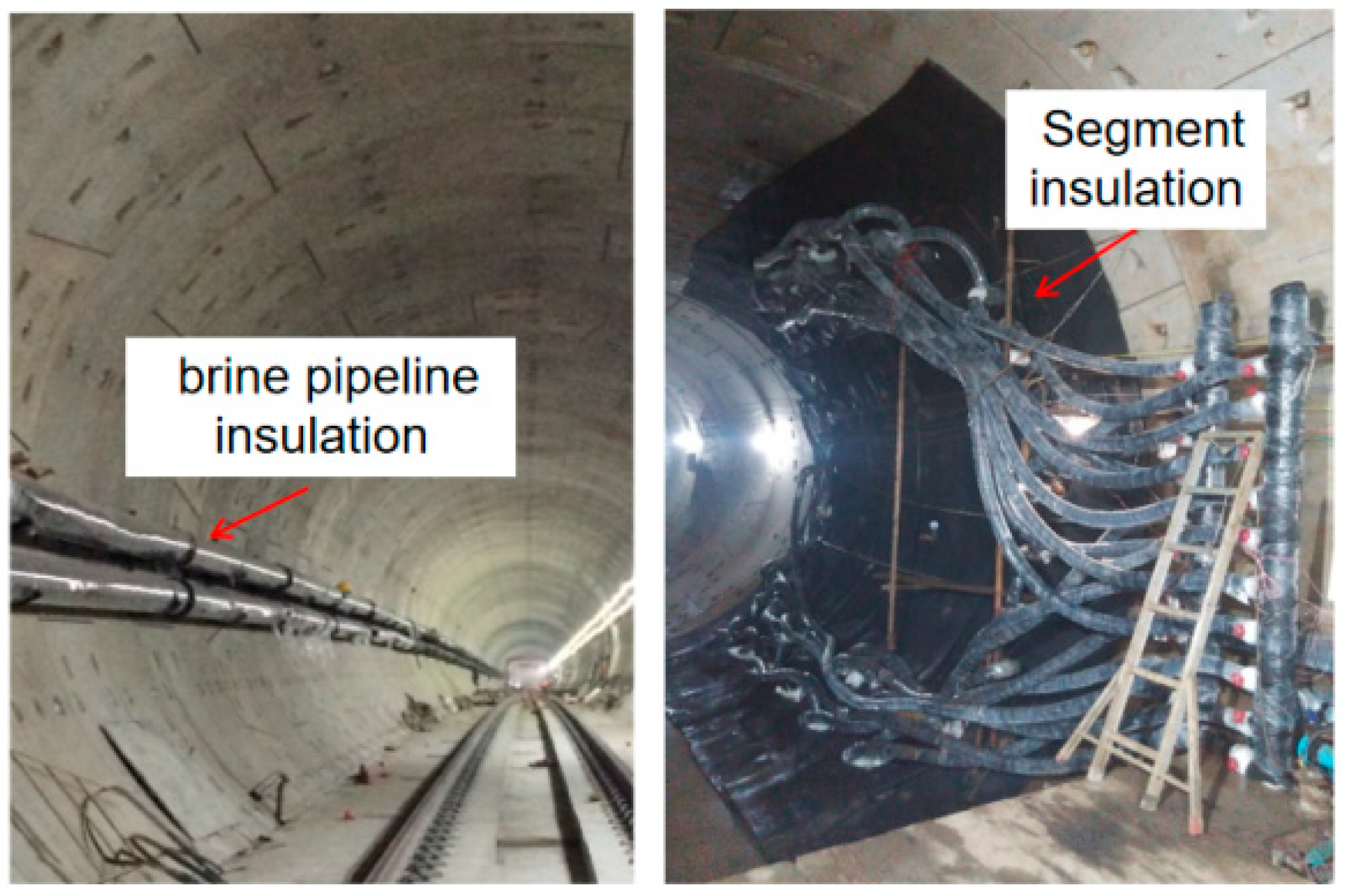
In the process of brine transportation in an ultra-long pipeline, it is a key issue to ensure the freezing effect by decreasing the temperature rise of brine in the transportation process. In this project, the medium- and low-pressure vessels, pipelines, brine tanks, main pipe, collection pipes, and low-temperature pipelines of the brine circulation system were all subjected to thermal insulated treatment (Figure 9) to make the outer surface temperature about 2 °C higher than that of the ambient dew point temperature, hence no condensation water can be generated. The insulation layer was made of polystyrene foam plastic, whose thermal conductivity was less than 0.17 kJ/mh°C.
When installing the brine pipeline, two layers of polystyrene insulating board with a thickness of 20 mm were used for double-layer heat insulation, and the outer layer of each insulating board was wrapped with plastic film. After the installation of the pipeline, the thermally insulated and strengthened operation on the flange connection of the brine pipeline was carried out at the same time once the test pressure was qualified. The cotton wool was used as the insulated layer of the evaporator and low-temperature pipelines of the refrigerating battery, and polystyrene foam plastic insulating board with a thickness no less than 30 mm was laid out on both sides of the connection aisle in the frozen and reinforced area, and the grille of the steel pipe was filled with plain concrete.
- (3)
- Brine flow and pressurization methods
The pressure of brine will decrease gradually at the long brine transportation pipe in this project. In addition, the poor sealing at individual locations will also lead to the appearance of gas in the pipeline and, accordingly, affect the delivery of brine and the freezing of stratum. In order to ensure that the flow and pressure of brine meet the freezing requirements of the connection aisle, the booster pump and exhaust valve were installed on the delivery line of brine. The gas can be exhausted by the exhaust valve at the necessary moment to ensure that the flow and pressure of brine in each freezer meet the requirements of freezing and soil reinforcement.
3.2.3. Anti-Interference Methods in Cross-Construction
The construction of the connection aisle cannot be carried out after the run-through of the tunnel due to the limitations of the construction period; therefore, the synchronous construction method of the connection aisle and shield driving of the tunnel were used. A door-like scaffold working platform was set up at the connection aisle, and construction of the frozen holes was carried out orderly according to the construction procedure. In addition, a temporary mechanical material stacking platform with a length of 20 m and a width of 0.6 m was set up on one side of the connection aisle. In the process of shield tunneling, the sewage pipe at the position of the connection aisle was set as a three-way pipe with a ball valve to ensure the smooth discharge of sewage during the construction of the freezing hole. Therefore, the interplay between shield excavation and frozen hole drilling was effectively reduced by using the above method.
After the frozen soil of the connection aisle meets the design requirements, in order to reduce the interplay between the track laying and the excavation of the connection aisle, the pre-stressed ring support (as shown in Figure 10) was used to replace the traditional well-shaped temporary internal support to ensure the smooth passage of the railcar. At the same time, in order to reduce the damage to the brine pipeline caused by collisions during the track laying process, a clamping band containing a rubber lining with an inner diameter of 159 mm and a length of 200 mm was made for the main brine pipeline and a clamping band with an inner diameter of 89 mm and a length of 100 mm for the high-pressure rubber pipeline to ensure that there is no need to stop the machine in case of slight damage to the brine pipeline, and meanwhile, the damage can be repaired quickly.
4. Results and Discussion
4.1. Monitoring Analysis of the Freezing Effect of the Long-Distance Stratum
The monitoring data of the temperature measurement hole and pressure relief hole in the process of freezing reinforcement is an important basis for evaluating the development law of the frozen wall and the strata freezing effect. In order to understand the development of frozen walls in different parts, temperature measuring holes and pressure relief holes were laid out on the upper, lower, and both sides of the connection aisle to monitor and analyze the freezing effect of the stratum.
4.1.1. Monitoring and Analysis of Brine Temperature
The total length of the brine delivery and return pipelines in this typical project was about 2.2 km. In order to ensure that monitoring data can accurately judge and reflect the freezing and reinforcement situation of the connection aisle strata, two temperature measurement points were set on both the delivery and return pipelines to monitor the real-time temperature of the brine. Figure 11 shows the temperature–time variation curve of the brine delivery and return pipelines.
It can be seen that the temperature of brine in the delivery and return pipelines decreases linearly from startup to 27 d of freezing and reaches the design control goal, that is, brine temperature is less than −18 °C at 7 d, −24 °C at 15 d, and −28 °C at the beginning of tunneling. This indicates that the refrigerating capacity of the frozen station is abundant, and the relevant refrigeration equipment, cooling equipment, ventilation and heat dissipation equipment, booster pump, and thermal insulation devices are all in normal operation.
Figure 12 shows the variation curve of the temperature difference of the brine in delivery and return pipelines with time. As shown in the figure, the temperature difference of the brine in delivery and return pipelines shows a certain fluctuation with time, but overall takes on a decreasing trend with freezing time. After freezing for 25 d, the temperature difference becomes stable gradually, with a slight change between 1 °C and 1.5 °C. The above phenomenon indicates that in the early stage of freezing, the cooling requirement of the soil is large and the heat exchange between the soil and brine is greater. Therefore, the temperature difference between the brine in delivery and return pipelines is large at the early stage of freezing. As the frozen wall develops, the decrease in thermal load of the strata is less, and the frozen wall forms and encloses, so the freezing effect of the strata around the connection aisle is good.
4.1.2. Monitoring and Analysis of Frozen Wall Temperature Measuring Hole
Ten temperature measurement holes were laid out inside and outside the connection aisle and on both sides of the tunnel, respectively, to fully observe the strata temperature changes during the freezing process and determine the development status of the frozen wall. Among them, two temperature measurement holes were laid out on the right tunnel, and eight temperature measurement holes were laid out on the left tunnel. The depth of each temperature measurement hole ranged from 3 m to 4.4 m, and three measurement points in each temperature measurement hole were arranged uniformly from shallow to deep. Figure 13 shows the temperature variation of each measuring point in temperature measuring hole C5 with time. It can be seen that from the beginning of freezing to 27 d, the temperature of the three measuring points shows a consistent decreasing trend. In the early stage of freezing, the temperature of each measuring point decreases linearly with time. After freezing for 27 d, the temperature of the frozen wall stabilizes gradually, and the average temperature is less than the designed temperature of −10 °C. Comparing Figure 13 with Figure 11, it can be seen that the temperature change in the frozen wall shows a good correlation with that of the brine in delivery and return pipelines, which indirectly proves the effectiveness of soil freezing reinforcement. In addition, it can also be seen that, because of the influence of the external environment, the closer the distance between the temperature measurement point (C5-1 point in Figure 13) and the segment (the buried depth is about 3 m), the higher the temperature value is.
4.1.3. Monitoring and Analysis of Frozen Wall Pressure Relief Holes
During the freezing process of soil, the water inside the soil migrates due to the frost heave effect. After the frozen wall encloses, because the water and soil inside the frozen wall lose contact with the outside, the pressure of water and soil increases accordingly, which increases gradually with the increase in volume of the frozen soil inside the frozen wall until the inner wall is frozen.
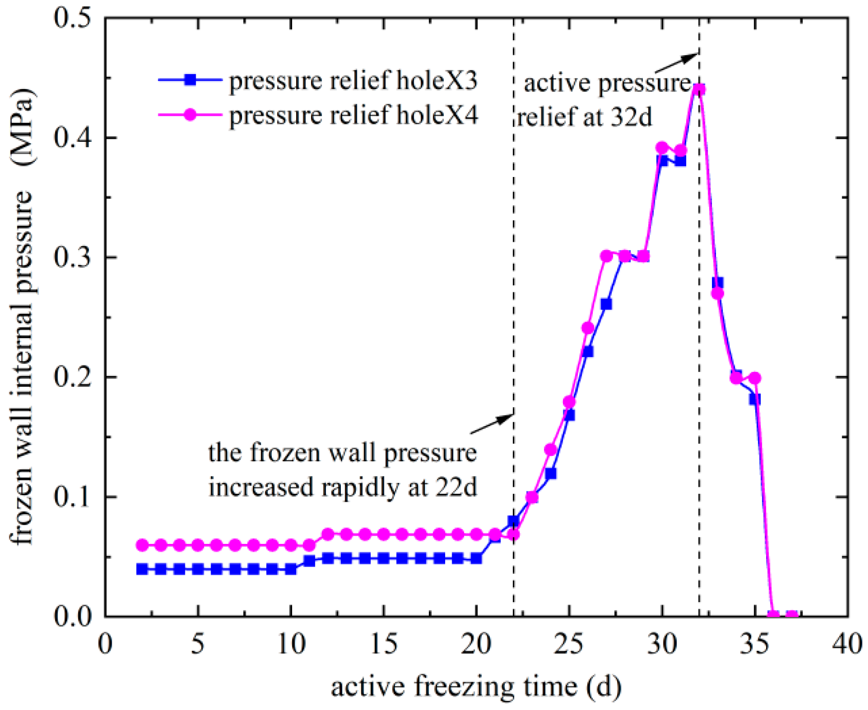
In order to release the frost heave pressure inside the frozen wall and ensure the freezing density inside the frozen wall, two pressure relief holes were laid out in the middle of the frozen wall of the connection aisle (namely, the left and right lines of the tunnel), respectively, to obtain the freezing situation accurately inside the frozen wall. The change in pressure with time of the pressure relief holes (X3 and X4, as shown in Figure 1) in the frozen wall before excavation of the connection aisle is shown in Figure 14. At the beginning of the freezing of the connection aisle, because the frozen wall does not enclose it, the pressure measured by the pressure relief hole is just the initial crustal stress. With the increase in freezing time, the frozen wall encloses gradually, and the freezing pressure increases rapidly. In order to ensure the freezing quality inside the frozen wall, the pressure is released when it increases to about 0.4 MPa. With increasing the depth of frozen soil, the unfrozen area decreases gradually, so the freezing pressure will show a larger growth rate after pressure relief. It can be seen from Figure 14 that the frozen wall encloses after freezing for about 22 d. At this moment, the pressure in the pressure relief hole begins to increase sharply. The pressure relief is used to control the freezing pressure rising speed during the freezing process, and the highest value of the freezing pressure is about 0.46 MPa. According to the relevant strength parameters of frozen soil in Table 2, this pressure will not cause cracking and damage to the frozen wall.
4.2. Freezing Effect Analysis and Evaluation
A quantitative relationship between the thickness of the frozen wall and the average temperature of the frozen wall during the freezing process is established by using the Trupak freezing theory [28], and further evaluation of the freezing effect of the connection aisle is conducted based on the monitoring data. According to Trupak’s theory, the freezing problem of strata can be approximated and regarded as a steady-state thermal conductivity problem, and the single-pipe freezing temperature field distribution model is established as follows:
where t(r) is the temperature at r point from the freezing pipe axis; r is the distance from the calculation point to the freezing pipe axis; ξ is the radius of the frozen wall of a single pipe; r0 is the outer diameter of the freezing pipe (here, it was 0.045 m); tct is the temperature of the outer surface of the freezing pipe; and t0 is the freezing temperature when the strata begins to freeze, which is approximately −3.9 °C according to the pre-test of freezing construction in this project.
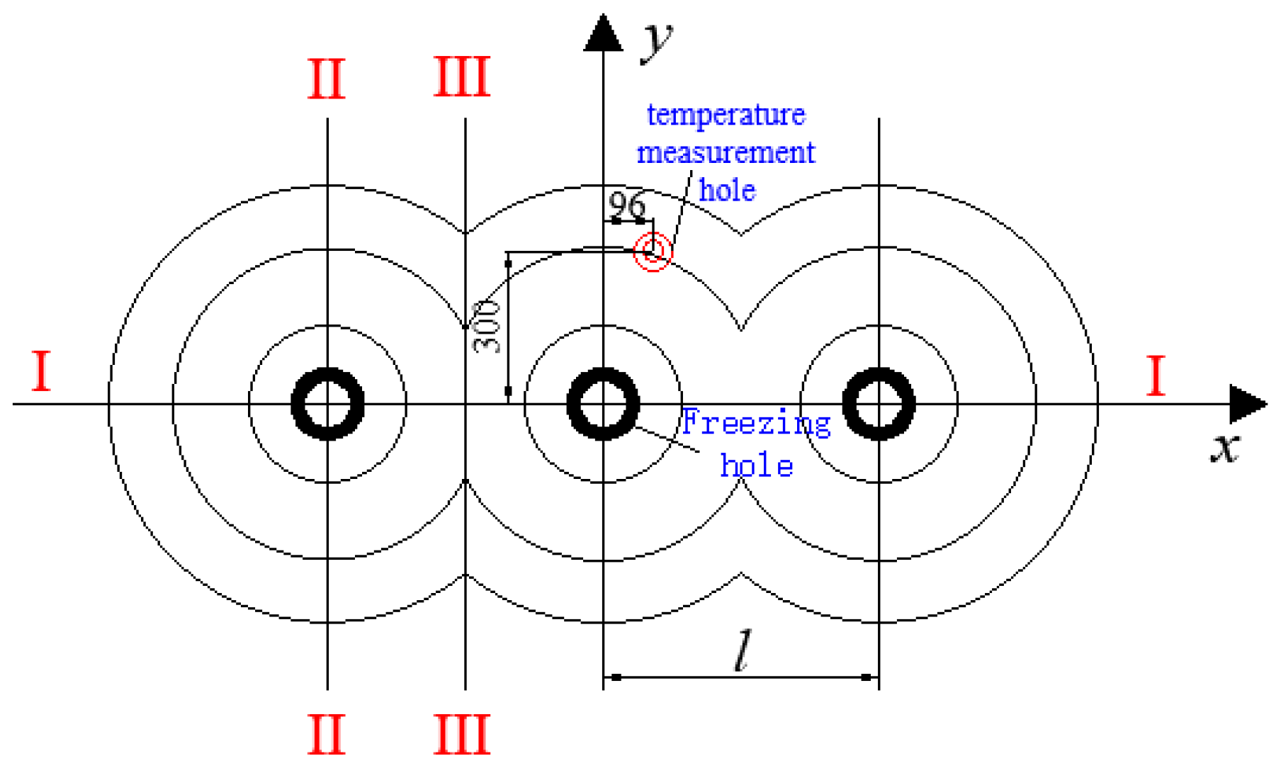
The relative position relationship between the horizontal temperature measuring hole C8 and the freezing pipe in this project is shown in Figure 15, where the planes of I-I, II-II, and III-III are the axial plane, the main plane, and the interface of the three characteristic planes of the Trupak freezing theory, respectively.
Trupak [28] and Bakholdin [29] point out that the mean temperature (tcp) of the frozen wall can be calculated as the mean temperature of the main plane I-I and the interface III-III.
where tcpz and tcpj are the temperatures of the main plane and the interface, respectively. The expression of tcpz is as follows:
According to the linear distribution rule, the temperature of interface III-III tcpj can be approximately fitted as follows:
where tk is the temperature at the intersection of the frozen wall axis plane and the interface, and l is the spacing between the frozen holes.
Equations (5)–(7) show the relationship between the frozen wall thickness and the average temperature based on the Trupak theory.
The required average temperature of the frozen wall satisfying the design thickness requirement of 2.2 m under different freezing temperatures of strata can be calculated, as shown in Table 5.
According to Table 5, as the freezing temperature of the soil decreases, the required average temperature of the frozen wall also decreases. When the freezing temperature of the strata in the connection aisle is −3.9 °C, the average temperature of the frozen wall satisfying the design thickness requirement of 2.2 m is about −9.7 °C. The design value of the average temperature of the frozen wall in this project is −10 °C, as shown in Table 2, which meets the design thickness requirement of 2.2 m of the frozen wall. In addition, the onsite measured data shows that the average soil temperature in the C8 temperature measurement hole reaches −13.9 °C, which is lower than the designed limiting value of 10 °C, meeting the design requirements. The onsite excavation process shows that the freezing effect of the connection aisle and surrounding strata is good, and there are no safety issues such as water and mud surging during construction.
Overall, this study uses a simplified energy calculation formula for the criterion to calculate the heat absorption and cooling capacity of the refrigeration system [27]. However, it does not account for the heat exchange involved in transporting the freezing fluid over long distances, the influence of the thermal conductivity of soils, and hydrothermal phase change on the freezing effect. This simplification is made for engineering convenience, potentially resulting in a conservative energy calculation. The measured data indicates a favorable freezing effect. The evaluation of the freezing effect using Trupac theory means that the method proposed in this study aligns with the practical needs for freezing the connection aisle. To improve the accuracy of freezing energy calculation and freezing effect evaluation, future research will focus on the calculation of the coupled hydro-thermo–mechanical interaction of frozen soil.
4.3. Comparative Analysis of Various Freezing and Construction Methods
Typically, the excavation of the connection aisle commences after assembling the tunnel tubes on both sides and establishing the freezing stations inside the tunnel [26,30]. This method has advantages in terms of pipeline arrangement, freezing fluid insulation, and energy conservation. However, the method might not be optimal for projects with an accelerated schedule. The long-distance temperature control method used in this study enables the simultaneous excavation of tunnels and connection aisles, leading to efficiency improvement and time savings. Chen et al. [31] demonstrated that employing a similar method can advance the tunnel excavation by approximately 60 days and the connection aisle excavation by about 45 days, leading to construction cost savings. Yang [32] systematically studied the effect of distant cold transmission freezing, with a distance reaching up to 260 m, offering valuable insights for tunnel excavation. Faced with increasingly complex working conditions and construction requirements, the long-distance temperature control system also possesses unique advantages, particularly in terms of time savings, which is crucial for engineering and construction despite the potentially high temperature control costs. Concurrently, this study establishes the methodology and foundation for designing the freezing system, elucidates the technical aspects of long-distance freezing and reinforcement construction over 1000 m, and defines the detailed design and construction parameters. This holds practical guidance significance for future subway connection aisle construction.
5. Conclusions
Relying on the freezing construction project of the connection aisle of Wuhan subway line 21, the basic principles and critical technology of freezing design and construction of the long-distance stratum were explored. The corresponding design methods and techniques were proposed, and the validity of the freezing construction program with a long distance was evaluated based on the measured data and theoretical analysis. The following conclusions are drawn:
- (1)
- A freezing construction technology of long-distance low-temperature brine transportation for the synchronous construction of frozen stratum excavation of a subway connection aisle, shield tunneling, and track laying was developed. The design method and basis of the refrigeration system were determined, as were the technical points for long-distance freezing reinforcement construction and the detailed design and construction parameters. The proposed method can save time and has strong practical guidance for future subway connection channel construction.
- (2)
- The initial freezing period requires significant soil cooling, leading to a linear decrease in the brine temperature in the delivery and return pipelines. As the frozen wall develops gradually, the reduction in the heat load of the strata is less, resulting in a gradual stabilization of the brine temperature after around 27 days of freezing. The overall temperature difference of the brine between delivery and return pipelines also decreases gradually and stabilizes eventually over time.
- (3)
- The temperature at each measuring point of the frozen wall decreases linearly with time in the early stage and gradually tends to be stable in the later stage, and the average temperature reaches the designed temperature of −10 °C. It means that good freezing performance can be guaranteed by using insulation and pressurization equipment. The door-like scaffold and pre-stressed ring support can reduce the interplay of excavation of the connection aisle, tunnel excavation, and track laying.
- (4)
- By strategically placing pressure relief holes and managing the rate of pressure, the pressure within the frozen wall can be maintained below 0.5 MPa, preventing cracks and damage.
- (5)
- The average freezing curtain temperature is −13.9 °C, which accords with the Trupac theory of −9.7 °C and meets the design requirements of engineering.
- (6)
- It is essential in future studies to consider additional details, including hydrothermal phase change, the impact of salt content on freezing temperature, and the influence of soil thermal conductivity. Moreover, additional field test data are required to validate and enhance the design method, making it more suitable for diverse soil types.
Author Contributions
Methodology, G.S.; Formal analysis, W.Z.; Investigation, P.L.; Writing—original draft, Y.X.; Writing—review & editing, Q.L. All authors have read and agreed to the published version of the manuscript.
Funding
This study was funded by the Wuhan City College Teaching and Research Project (grant number: 2023CYYBJY013) and Scientific Research Project (grant number: 2022CYYBKY02), the National Natural Science Foundation of China (grant numbers: 52178182, 52108262, and U1934217), and the Science and Technology Research and Development Program Project of China Railway Group Limited (Major special projects, Nos.: 2020-Special-02, 2021-Special-08, and 2022-Special-09; Major project, No.: 2021-Special-02; and Key projects, No.: 2021-Key-11 and No.: 2022-Key-46). The authors also received research grants from the Natural Science Foundation for Distinguished Young Scholars of Hunan Province (2022JJ10075), the Natural Science Foundation of Hunan Province of China (2020JJ5982), and the Hunan Science and Technology Plan Project (2023SK2014).
Institutional Review Board Statement
Not applicable.
Informed Consent Statement
Not applicable.
Data Availability Statement
All relevant data are within the paper.
Acknowledgments
The authors thank the Wuhan City College Teaching and Research Project and Scientific Research Project, the National Natural Science Foundation of China, the Science and Technology Research and Development Program Project of China Railway Group Limited, the National Science Foundation for Distinguished Young Scholars of Hunan Province, the Natural Science Foundation of Hunan Province of China, and the Hunan Innovative Province Construction Special Project for funding this research, as well as anonymous reviewers for their contribution to this paper.
Conflicts of Interest
Author Qiang Liu was employed by the company Wuhan United Investments and Properties Co., Ltd. Guangqiang Shao was employed by the company China Construction Second Engineering Bureau Ltd. The remaining authors declare that the research was conducted in the absence of any commercial or financial relationships that could be construed as a potential conflict of interest.
References
- Wu, P.; Chen, Q.; Chen, Y.; Chen, S.; Zou, J. ISM-MICMAC based safety risk sources analysis and control measures for underground engineering of urban rail transit projects. J. Eng. Res. 2023, 153, 107550. [Google Scholar]
- Zhao, C.; Lei, M.; Shi, C.; Cao, H.; Yang, W.; Deng, E. Function mechanism and analytical method of a double layer pre-support system for tunnel underneath passing a large-scale underground pipe gallery in water-rich sandy strata: A case study. Tunn. Undergr. Space Technol. 2021, 115, 104041. [Google Scholar] [CrossRef]
- Shi, Z.; Xu, J.; Xie, X.; Zeng, H.; Xu, W.; Niu, G.; Xiao, Z. Disaster mechanism analysis for segments floating of large-diameter shield tunnel construction in the water-rich strata:A case study. Eng. Fail. Anal. 2024, 157, 107953. [Google Scholar] [CrossRef]
- Chen, R.; Cheng, G.; Li, S.; Guo, X.; Zhu, L. Development and prospect of research on application of artificial ground freezing. J. Geotech. Eng. 2000, 22, 40–44. [Google Scholar]
- Liu, X.; Shen, Y.; Zhang, Z.; Liu, Z.; Wang, B.; Tang, T.; Liu, C. Field measurement and numerical investigation of artificial ground freezing for the construction of a subway cross passage under groundwater flow. Transp. Geotech. 2022, 37, 100869. [Google Scholar]
- Mauro, A.; Normino, G.; Cavuoto, F.; Marotta, P.; Massarotti, N. Modeling Artificial Ground Freezing for Construction of Two Tunnels of a Metro Station in Napoli (Italy). Energies 2020, 13, 1272. [Google Scholar] [CrossRef]
- Tounsi, H.; Rouabhi, A.; Tijani, M.; Guérin, F. Thermo-Hydro-Mechanical Modeling of Artificial Ground Freezing: Application in Mining Engineering. Rock Mech. Rock Eng. 2019, 52, 3889–3907. [Google Scholar] [CrossRef]
- Chang, D.K.; Lacy, H.S. Artificial Ground Freezing in Geotechnical Engineering. In Proceedings of the Sixth International Conference on Case Histories in Geotechnical Engineering, Chicago, IL, USA, 11–16 August 2008; Volume 5. [Google Scholar]
- Zhou, X.M.; Jiang, G.; Li, F.; Gao, W.; Han, Y.; Wu, T.; Ma, W. Comprehensive Review of Artificial Ground Freezing Applications to Urban Tunnel and Underground Space Engineering in China in the Last 20 Years. J. Cold Reg. Eng. 2022, 36, 273. [Google Scholar]
- Fan, W.; Yang, P. Ground temperature characteristics during artificial freezing around a subway cross passage. Transp. Geotech. 2019, 20, 100250. [Google Scholar] [CrossRef]
- Powers, P.P.; Corwin, P.E. Ground Freezing. In Construction Dewatering and Groundwater Control: New Methods and Applications; John Wiley & Sons: Hoboken, NJ, USA, 2007. [Google Scholar]
- Li, J.; Li, J.; Cai, Y.; Wu, D.; Guo, C.; Zhao, W.; Tang, K.; Liu, Y. Application of Artificial Freezing Method in Deformation Control of Subway Tunnel. Adv. Mater. Sci. Eng. 2022, 2022, 3251318. [Google Scholar]
- Teng, J.; Dong, A.; Yan, H.; Tong, C.; Zhang, S. Predicting the hydraulic conductivity of frozen coarse-grained soils. J. Hydrol. 2023, 617, 129048. [Google Scholar] [CrossRef]
- Zhang, K.; Guo, A.; Yu, Y.; Yang, B.; Yu, B.; Xie, C. Freeze–thaw damage degradation model and life prediction of air-entrained concrete in multi-year permafrost zone. Materials 2023, 16, 7703. [Google Scholar] [CrossRef]
- Golewski, G.L. The effect of the addition of coal fly ash (CFA) on the control of water movement within the structure of the concrete. Materials 2023, 16, 5218. [Google Scholar] [PubMed]
- Fu, Y.; Hu, J.; Wu, Y. Finite element study on temperature field of subway connection aisle construction via artificial ground freezing method. Cold Reg. Sci. Technol. 2021, 189, 103327. [Google Scholar] [CrossRef]
- Song, H.; Cai, H.; Yao, Z.; Rong, C.; Wang, X. Finite Element Analysis on 3D Freezing Temperature Field in Metro Cross Passage Construction. Procedia Eng. 2016, 165, 528–539. [Google Scholar] [CrossRef]
- Zhang, S.; Zhou, X.M.; Ma, W.; Liu, Y.; Lu, C. Longitudinal temperature acquisition system of ground freezing and its application in solving temperature field. Cold Reg. Sci. Technol. 2023, 213, 103911. [Google Scholar] [CrossRef]
- Hong, Z.; Hu, X. Application of Analytical Solution to Steady-State Temperature Field by Double-Row-Pipe Freezing and Verification with Field Measurement: A Case Study of Connected Aisle. Adv. Civ. Eng. 2019, 2019, 6435060. [Google Scholar] [CrossRef]
- Chen, J.; Zhang, Y.; Chen, B.; Zhao, Z.; Wang, Q. Development characteristics of freezing temperature field of coastal soft soil strata. Coal Geol. Explor. 2020, 48, 25. [Google Scholar]
- Hu, J.; Liu, Y.; Li, Y.; Yao, K. Artificial Ground Freezing In Tunnelling Through Aquifer Soil Layers:a Case Study in Nanjing Metro Line 2. KSCE J. Civ. Eng. 2018, 22, 4136–4142. [Google Scholar] [CrossRef]
- Yan, Q.; Xu, Y.; Yang, W.; Geng, P. Nonlinear Transient Analysis of Temperature Fields in an AGF Project used for a Cross-Passage Tunnel in the Suzhou Metro. KSCE J. Civ. Eng. 2018, 22, 1473–1483. [Google Scholar] [CrossRef]
- Hu, J.; Li, K.; Wu, Y.; Zeng, D.; Wang, Z. Optimization of the Cooling Scheme of Artificial Ground Freezing Based on Finite Element Analysis: A Case Study. Appl. Sci. 2022, 12, 8618. [Google Scholar] [CrossRef]
- Zhang, M.; Wan, H.; Yang, Y. Construction technology of the freezing method for the connecting-passage in the subway. In IOP Conference Series: International Conference on Oil & Gas Engineering and Geological Sciences, Dalian, China, 28–29 September 2019; IOP Publishing: Bristol, UK, 2019; Volume 384, p. 012090. [Google Scholar]
- Zhuang, Y.; Chen, J.; Zhang, J.; Wang, J.; Li, H. Analysis of the Development Characteristics and Influencing Factors of Freezing Temperature Field in the Cross Passage. Adv. Civ. Eng. 2021, 2021, 6645139. [Google Scholar] [CrossRef]
- Zhang, Y. Field Monitoring and Numerical Simulation of Subway Connection Tunnel Excavation Based on Freezing Method. Master’s Thesis, Taiyuan University of Technology, Taiyuan, China, 2022. (In Chinese). [Google Scholar]
- DB11/T 1972-2022; Technical Standard for Freezing Method Construction of Urban Rail Transit Engineering. China Architecture Publishing & Media Co., Ltd.: Beijing, China, 2022; pp. 10–11.
- Tрупак, Н.Г. Замoраживание Гoрных Пoрoд при Прoхoдкествoлoв; Углетехиздат: Moscow, Russia, 1954. (In Russian) [Google Scholar]
- Бахoлдин, Б.В. Выбoр Оптимальнoгo Режима Замoраживания Грунтoв в Стрoительных Целях; Гoсстрoйиздат: Moscow, Russia, 1963; pp. 21–27. (In Russian) [Google Scholar]
- Chen, K.; Dai, Z.; Zhang, H.; Wang, Y. Analysis of construction monitoring and temperature field of cross-passage of subway in seashore area in Xiamen using ground freezing method. J. Eng. Geol. 2023, 31, 1748–1756. (In Chinese) [Google Scholar]
- Chen, J.; Guo, Q.; Zhou, H.; Kui, W.; Dong, X. Construction scheme and application analysis of synchronous construction of subway shield tunnels and freezing reinforcement for cross passages. Mod. Tunn. Technol. 2023, 60, 233–241+248. (In Chinese) [Google Scholar]
- Yang, Z. Study on design optimization of long distance cold transportation and freezing system for bulk volume freezing project. Mine Constr. Technol. 2022, 43, 65–70. (In Chinese) [Google Scholar]
Figure 1.
Cross-section drawing of the frozen wall of the connection aisle (unit: m).
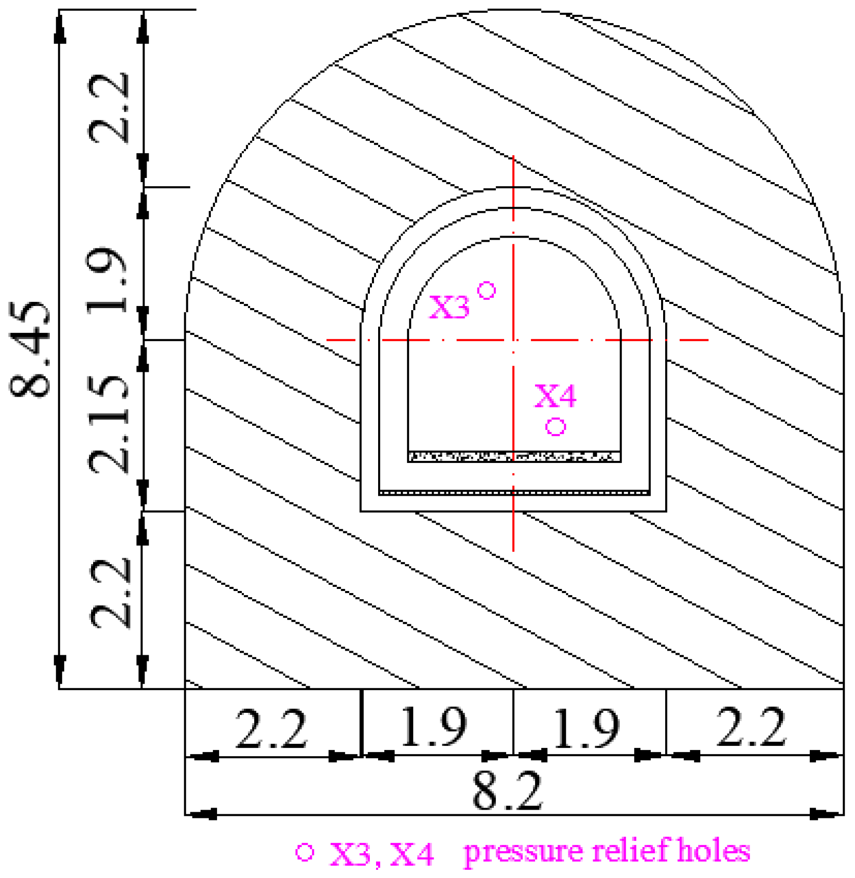
Figure 2.
Sectional view of connection aisle and positions of various monitoring holes (unit: m).

Figure 3.
Brine circulation refrigeration system.
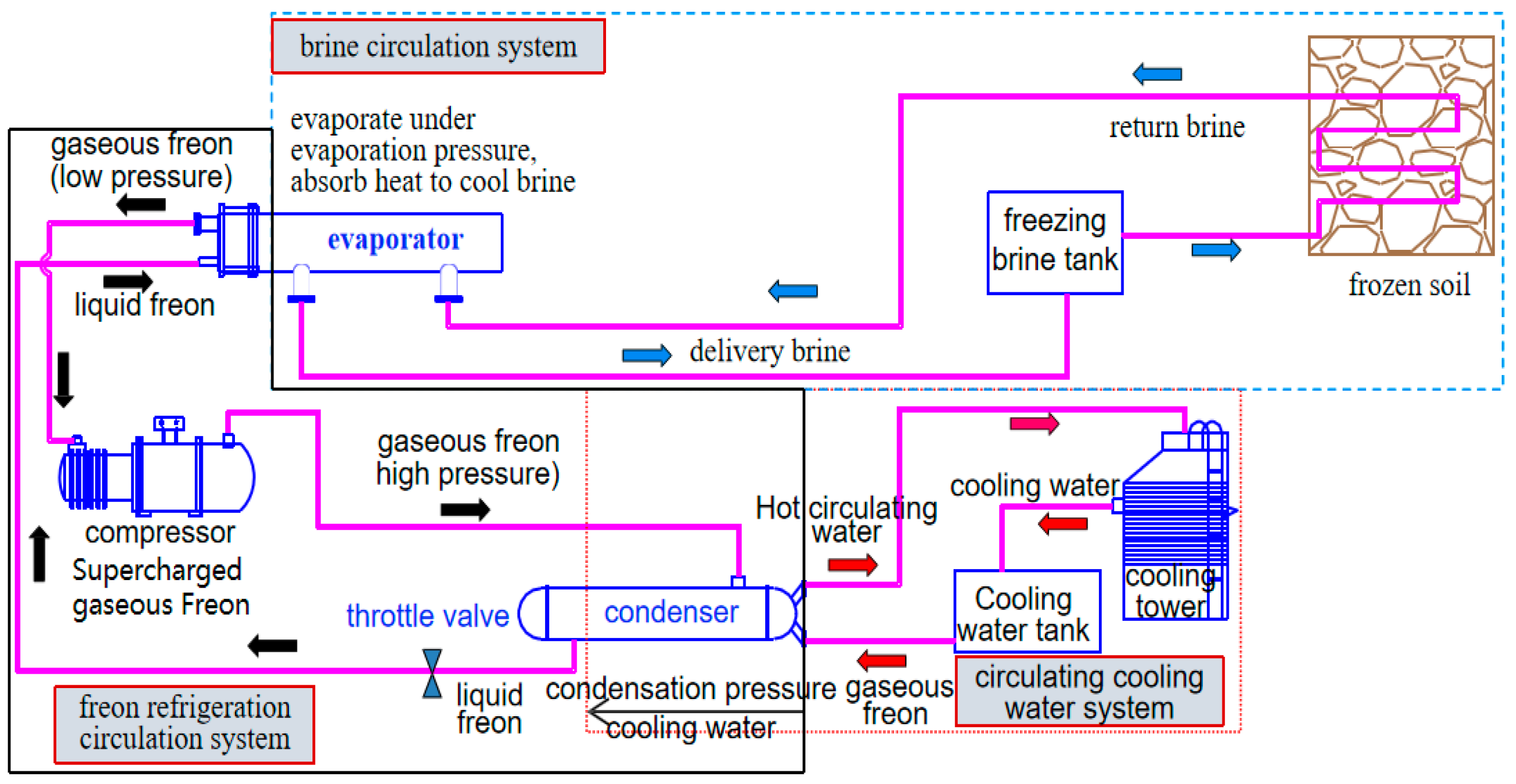
Figure 4.
Axial force diagram of the frozen wall structure on a normal cross-section of the aisle (unit: kN).
Figure 4.
Axial force diagram of the frozen wall structure on a normal cross-section of the aisle (unit: kN).
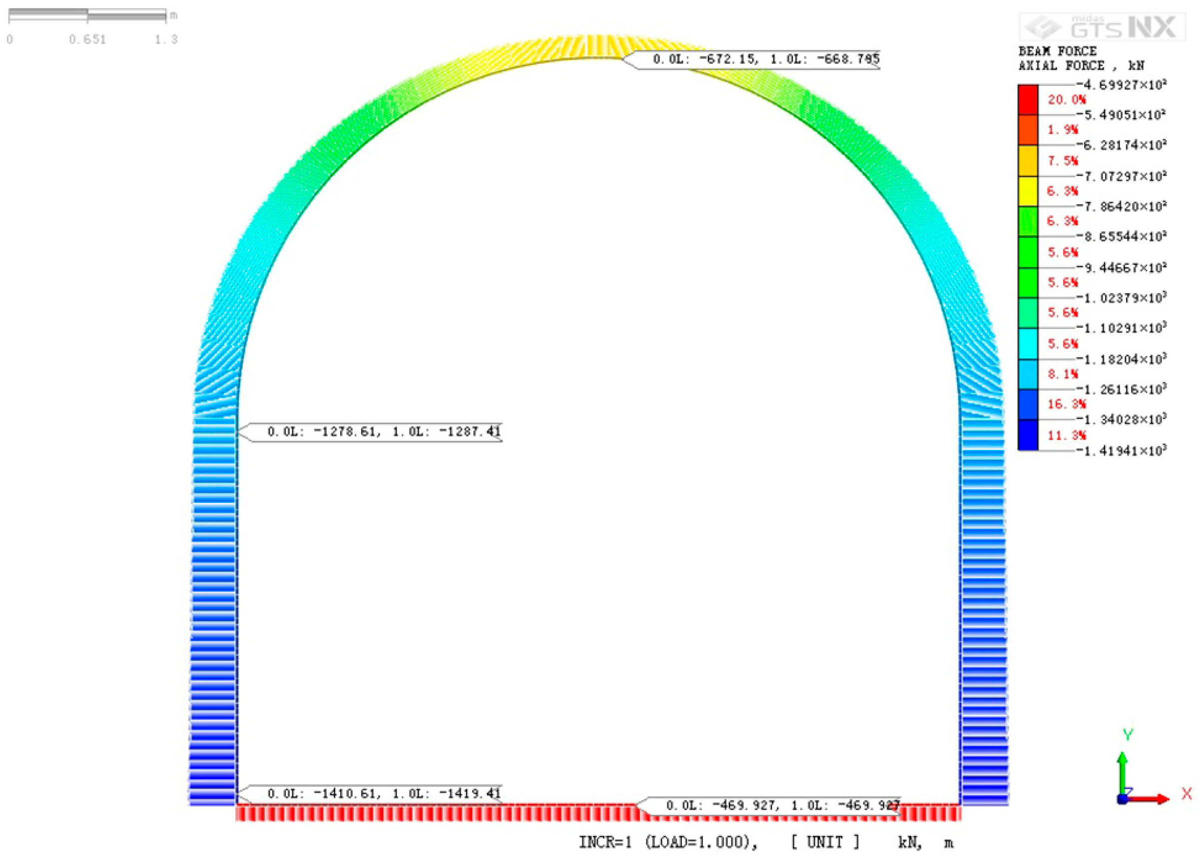
Figure 5.
Shear force diagram of the frozen wall structure on a normal cross-section of the aisle (unit: kN).
Figure 5.
Shear force diagram of the frozen wall structure on a normal cross-section of the aisle (unit: kN).
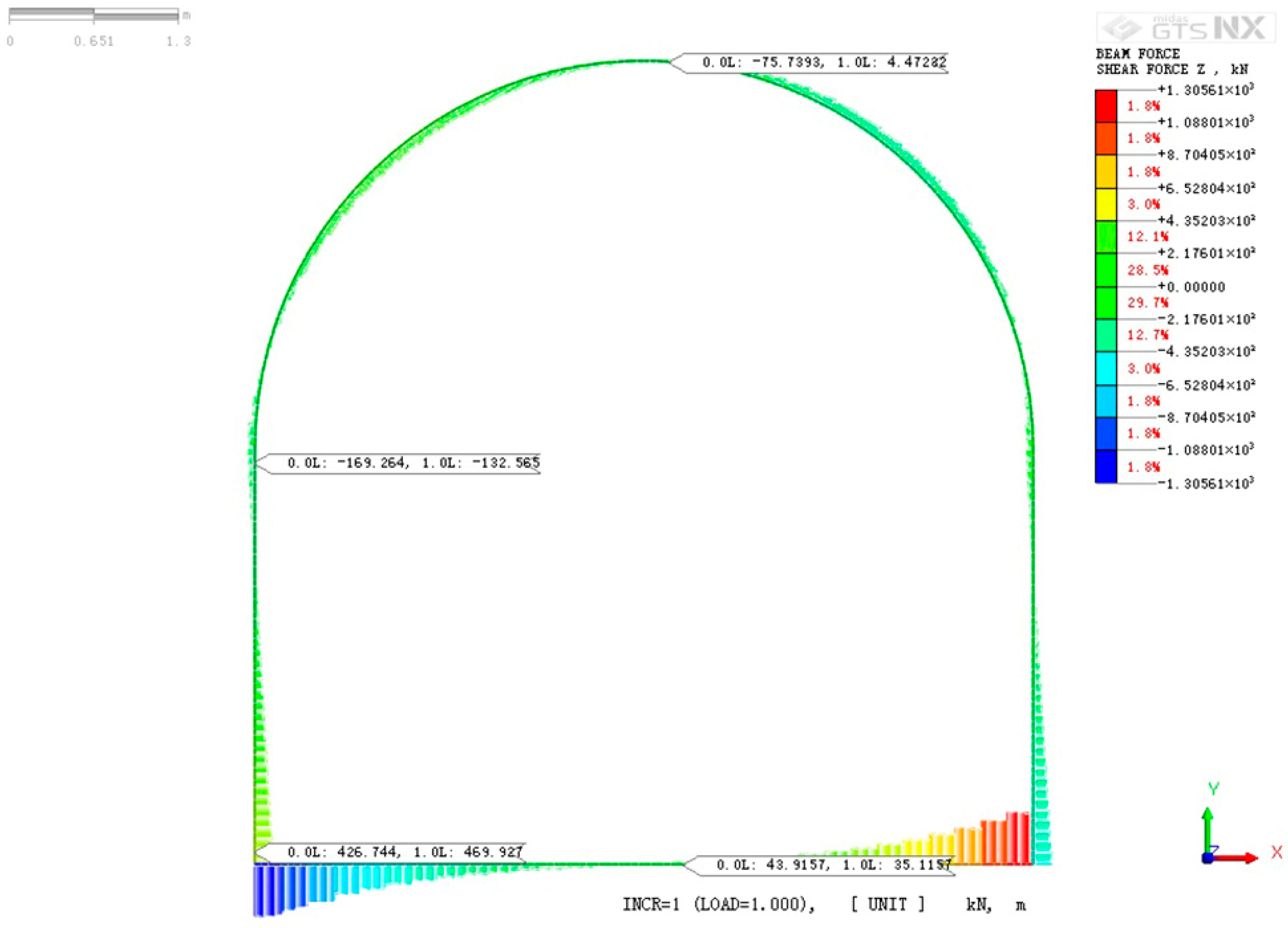
Figure 6.
Bending moment diagram of frozen wall structure on a normal cross-section of the aisle (unit: kN·m).
Figure 6.
Bending moment diagram of frozen wall structure on a normal cross-section of the aisle (unit: kN·m).
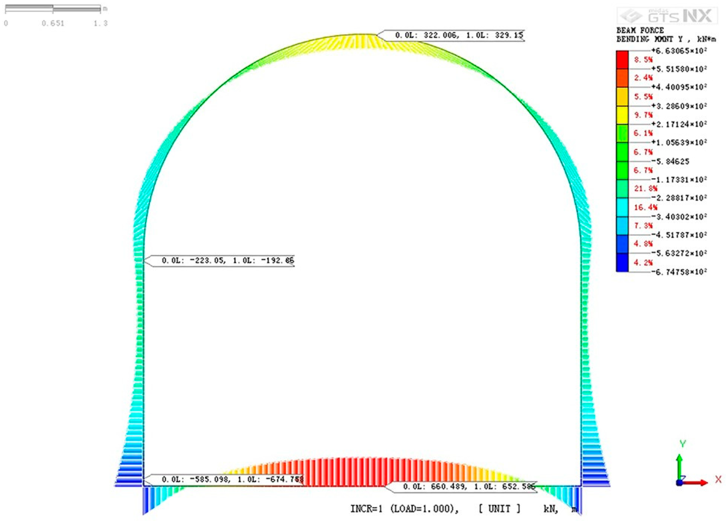
Figure 7.
Installation and fixation of the orifice.
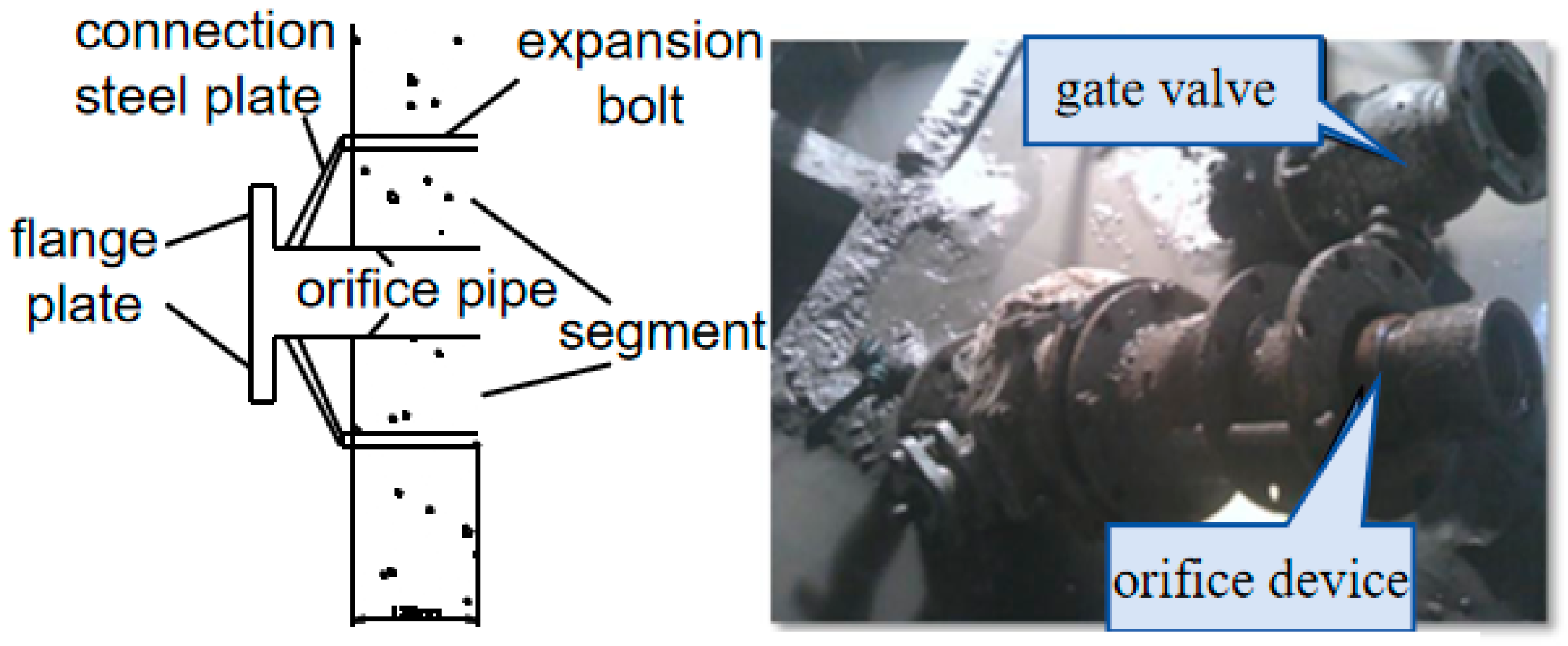
Figure 8.
Drilling of the holes.

Figure 9.
Heat insulation treatment of the brine pipeline and segment.

Figure 10.
Pre-stressed ring support diagram (unit: m).
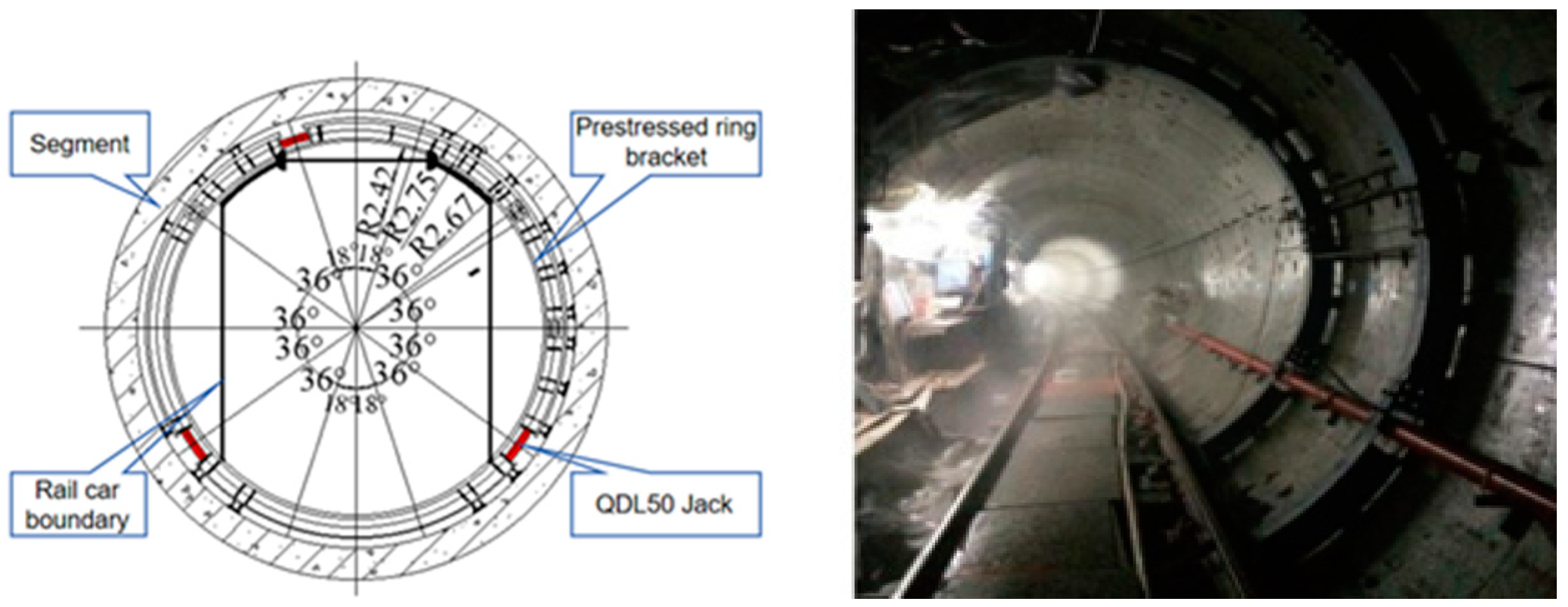
Figure 11.
The temperature changes in brine in delivery and return pipelines with time.
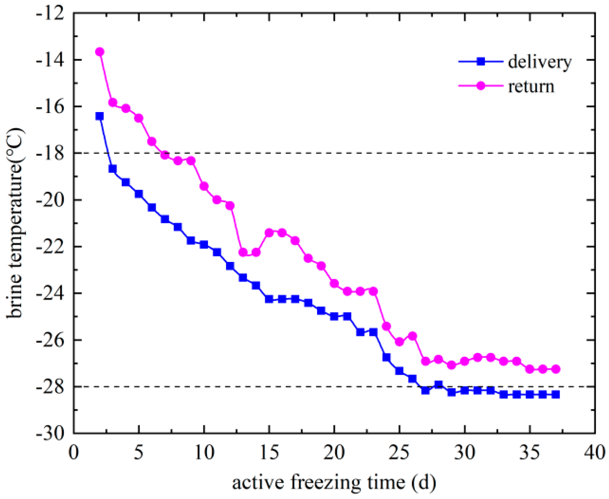
Figure 12.
The temperature difference changes in brine in delivery and return pipelines with time.
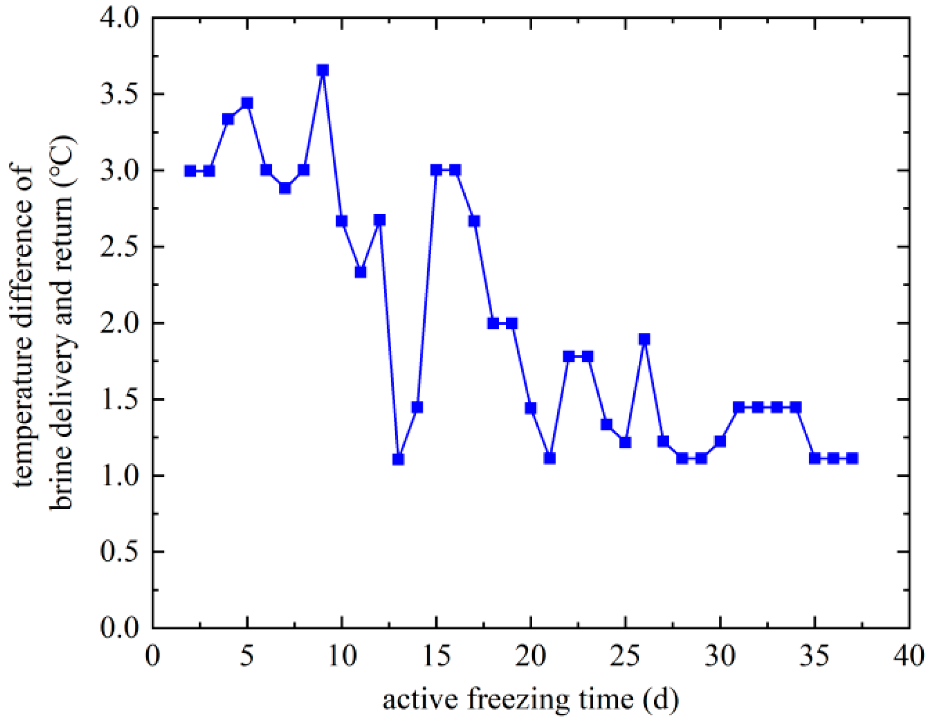
Figure 13.
The temperature changes in each measuring point in temperature measurement hole C5 with time.
Figure 13.
The temperature changes in each measuring point in temperature measurement hole C5 with time.
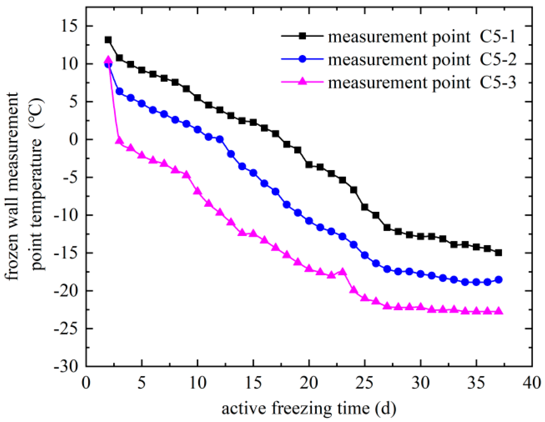
Figure 14.
Pressure variation in the pressure relief hole with time.

Figure 15.
Relative position of temperature measuring hole C8 and adjacent freezing hole (unit: cm).
Figure 15.
Relative position of temperature measuring hole C8 and adjacent freezing hole (unit: cm).


Table 1.
Major freezing engineering projects for general connection aisles.
| Engineering Name | Main Research Content |
|---|---|
| Nanning Subway Line No. 3 [16] | Investigating the development and spatial distribution of the temperature field during artificial freezing using three-dimensional finite element methods |
| Shanghai Metro Line No. 13 [17] | Modeling yields a detailed distribution pattern for freezing temperature fields |
| Guangzhou Metro [18] | Developed a longitudinal temperature acquisition system to address the inaccuracies in the determination of temperature fields |
| Maliuzhou Tunnel [19] | Exploring the optimal freezing scheme of double-circle freezing methods |
| Between Luoxiu Road Station and Baise Road Station of Shanghai Subway Line No.15 [20] | Analyzing the thickness and average temperature of frozen curtains and the freezing process |
| Between Xinjiekou Station and Shanghai Road Station of Nanjing Metro Line No. 2 [21] | Application of artificial ground freezing in tunnels through aquifer soil layers |
| Donggang West Road of Lanzhou Metro Line No. 1 [12] | Application of the freezing method for reinforcement and monitoring in the dangerous situation of mud and water inrush |
| Suzhou Metro [22] | Examining the evolutionary process of the freezing curtain |
| No. 2 connection aisle between the Gongzhongfu Station and the Inner Mongolia Stadium Station of Hohhot Metro Line 2 [23] | Evaluating the influence of different brine cooling schemes on the freezing process |
| Harbin Rail Transit Line 2 Dagengjia Station to Longchuan Road Station [24] | Introduces the construction scheme of the freezing method and analyzes the safety of the construction with the monitoring data |
Table 2.
Main design parameters of connection aisle freezing construction.
| Parameter Name | Unit | Design Value |
|---|---|---|
| Uniaxial compressive strength of frozen soil | MPa | 4 |
| Flexural strength of frozen soil | MPa | 1.8 |
| Shear strength of frozen soil | MPa | 1.5 |
| Frozen wall thickness | m | 2.2 |
| Average temperature of the frozen wall | °C | ≤−10 |
| Active freezing time | d | ≥55 |
| Maximum spacing between freezing holes | mm | 1500 |
| Freezing hole allowable deviations | mm | ≤150 |
| Minimum brine temperature | °C | −28 |
| Single-hole brine flow | m3/h | 5~7 |
| Freeze pipe specifications | mm | Φ89 × 8 Φ108 × 8 |
| Temperature measurement hole specifications | mm | Φ32 × 3.5 |
| Pressure relief hole specifications | mm | Φ32 × 3.5 |
Table 3.
Internal force values of the frozen walls on normal cross-sections of the aisle.
| Section Position | Internal Force Values | ||
|---|---|---|---|
| Axial Force (kN) | Shear Force (kN) | Bending Moment (kN·m) | |
| Corner of the wall | 1419 | 470 | 675 |
| Bottom plate | 470 | 44 | 660 |
Table 4.
Strength verification of the frozen walls at the corners of normal cross-sections of the aisle.
Table 4.
Strength verification of the frozen walls at the corners of normal cross-sections of the aisle.
| Project | Calculated Value/MPa | Strength Index/MPa | Safety Coefficient | |
|---|---|---|---|---|
| Compressive/bending stress | б1 | 0.43 | 1.80 | 4.23 |
| б3 | 1.69 | 4.00 | 2.36 | |
| Shearing stress | тmax | 0.37 | 1.50 | 4.03 |
Table 5.
Average temperature of the frozen wall.
| Strata Freezing Temperature/°C | Frozen Wall Thickness/M | Average Temperature of Frozen Wall/°C |
|---|---|---|
| 0 | 2.2 | −6.4 |
| −0.7 | 2.2 | −6.9 |
| −3.9 | 2.2 | −9.7 |
Disclaimer/Publisher’s Note: The statements, opinions and data contained in all publications are solely those of the individual author(s) and contributor(s) and not of MDPI and/or the editor(s). MDPI and/or the editor(s) disclaim responsibility for any injury to people or property resulting from any ideas, methods, instructions or products referred to in the content. |
© 2024 by the authors. Licensee MDPI, Basel, Switzerland. This article is an open access article distributed under the terms and conditions of the Creative Commons Attribution (CC BY) license (https://creativecommons.org/licenses/by/4.0/).
Share and Cite
MDPI and ACS Style
Xu, Y.; Liu, Q.; Zhi, W.; Shao, G.; Liu, P. Long-Distance Freezing Design and Construction Based on Monitoring Analysis of Subway Connection Aisle. Coatings 2024, 14, 355. https://doi.org/10.3390/coatings14030355
AMA Style
Xu Y, Liu Q, Zhi W, Shao G, Liu P. Long-Distance Freezing Design and Construction Based on Monitoring Analysis of Subway Connection Aisle. Coatings. 2024; 14(3):355. https://doi.org/10.3390/coatings14030355
Chicago/Turabian StyleXu, Yin, Qiang Liu, Weiting Zhi, Guangqiang Shao, and Peng Liu. 2024. "Long-Distance Freezing Design and Construction Based on Monitoring Analysis of Subway Connection Aisle" Coatings 14, no. 3: 355. https://doi.org/10.3390/coatings14030355
Note that from the first issue of 2016, this journal uses article numbers instead of page numbers. See further details here.