.jpg)
Exploring Sustainable Coating Solutions for Applications in Highly Corrosive Environments

 , ,
, ,  ,
,
Abstract
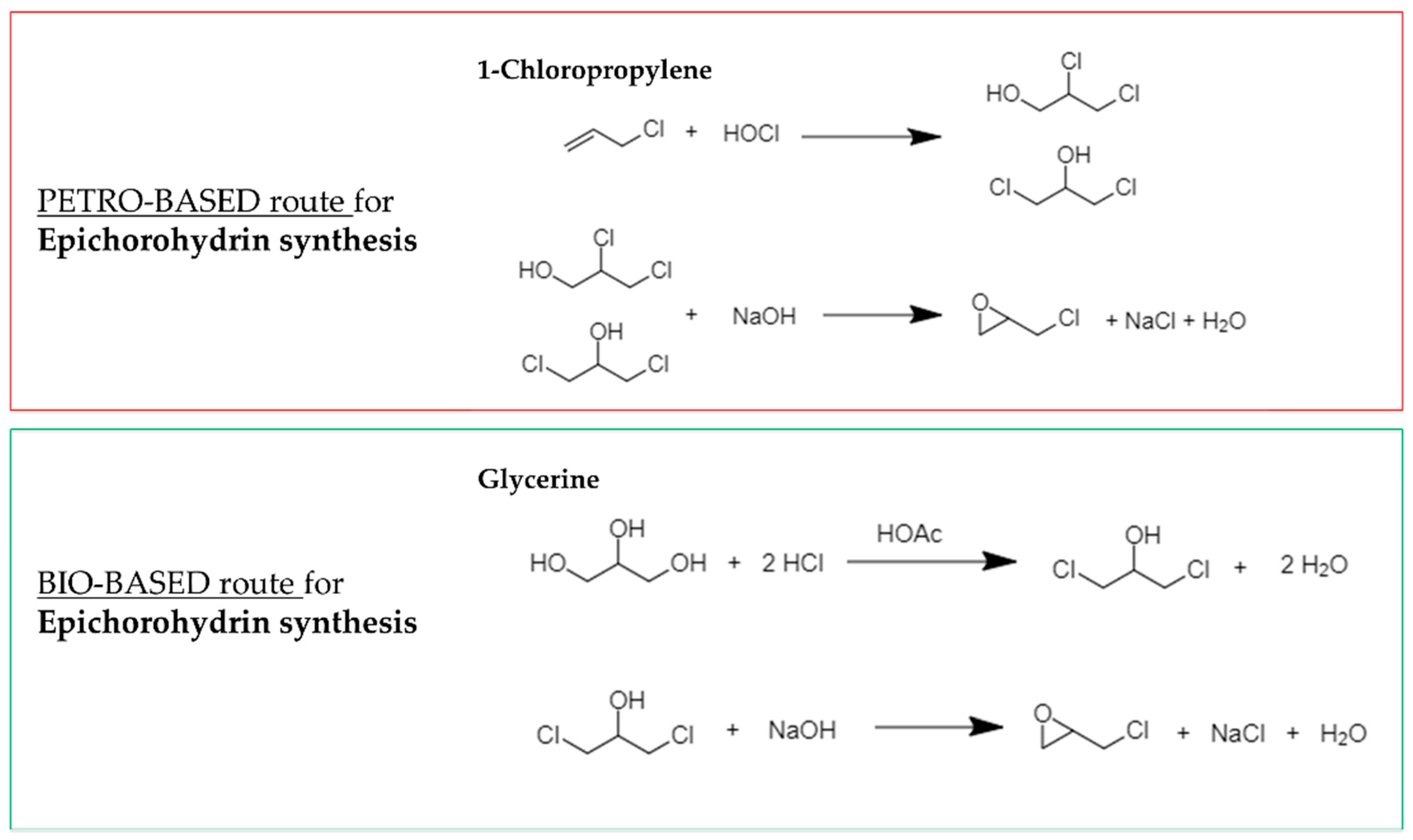
:1. Introduction
- -
- Primer: BPA-based Zn-rich solvent-based epoxy (Primer Reference Coating, PRC)
- -
- Middle coat: solvent-based epoxy (Middle Coating, MC)
- -
- Top-coat: solvent-based polyurethane (Top Coating, TC)
2. Materials and Methods
2.1. Materials
2.2. Coating Formulations
2.3. Preparation of Test Coupons and Characterization of Coatings
2.4. Artificial Laboratory Ageing
2.5. Field Exposure Condition
3. Results and Discussion
3.1. Coating Layer Characterization
3.1.1. Primer Coating Thickness
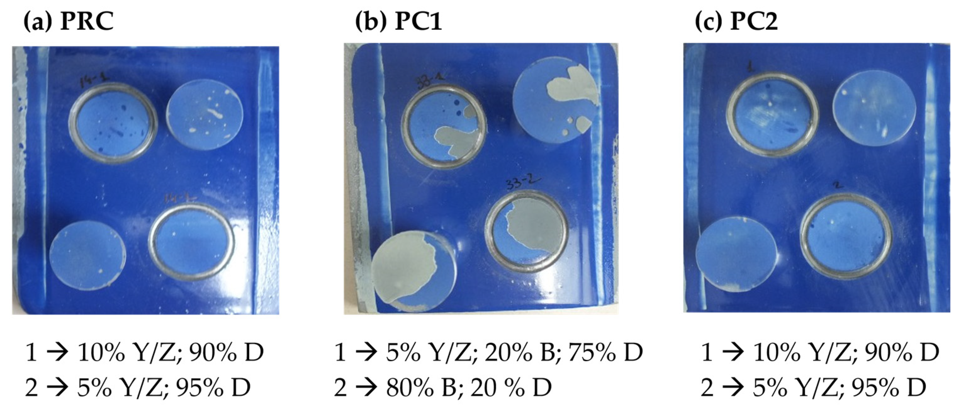
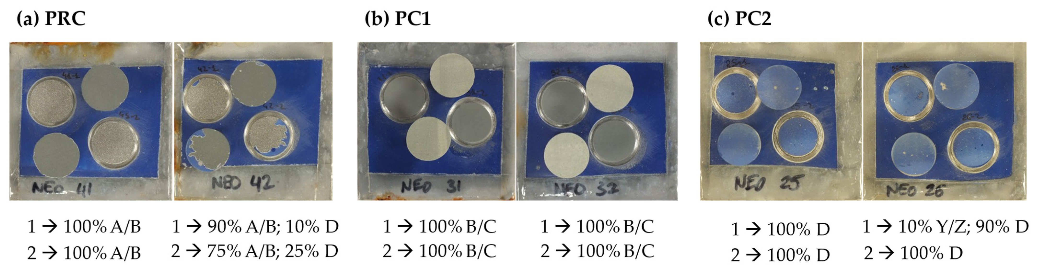
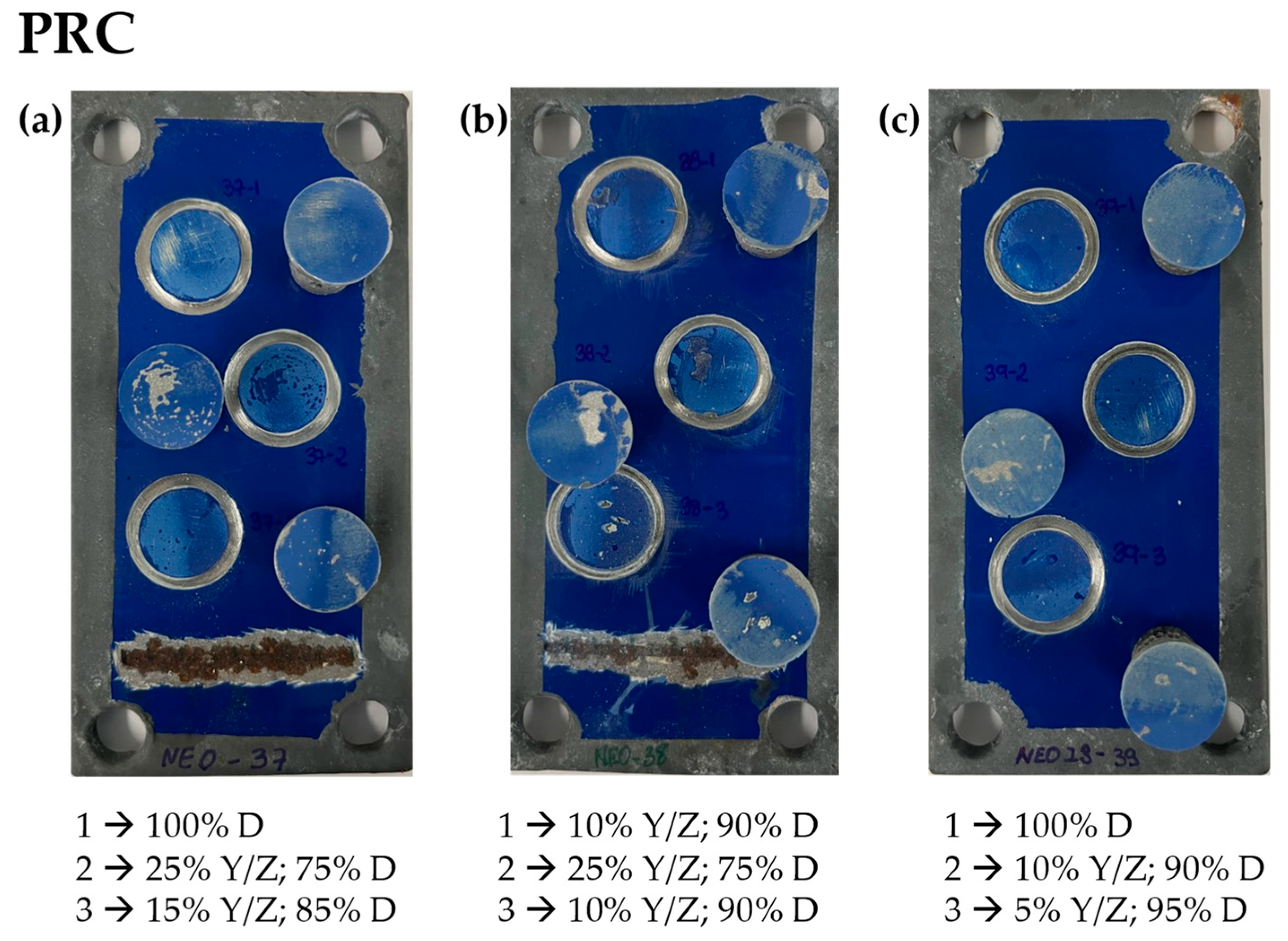
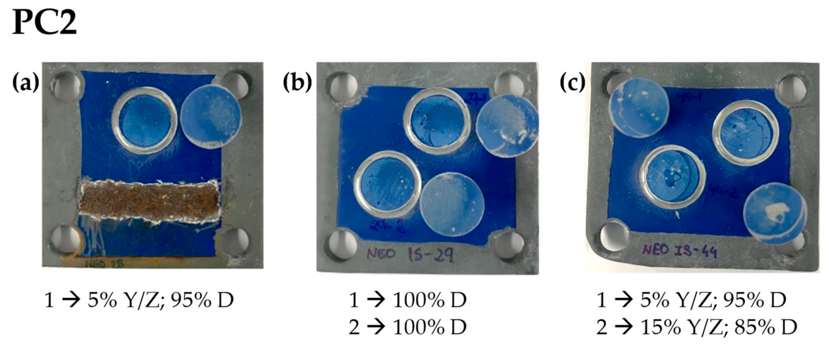
3.1.2. Corrosion Characterization of Primers
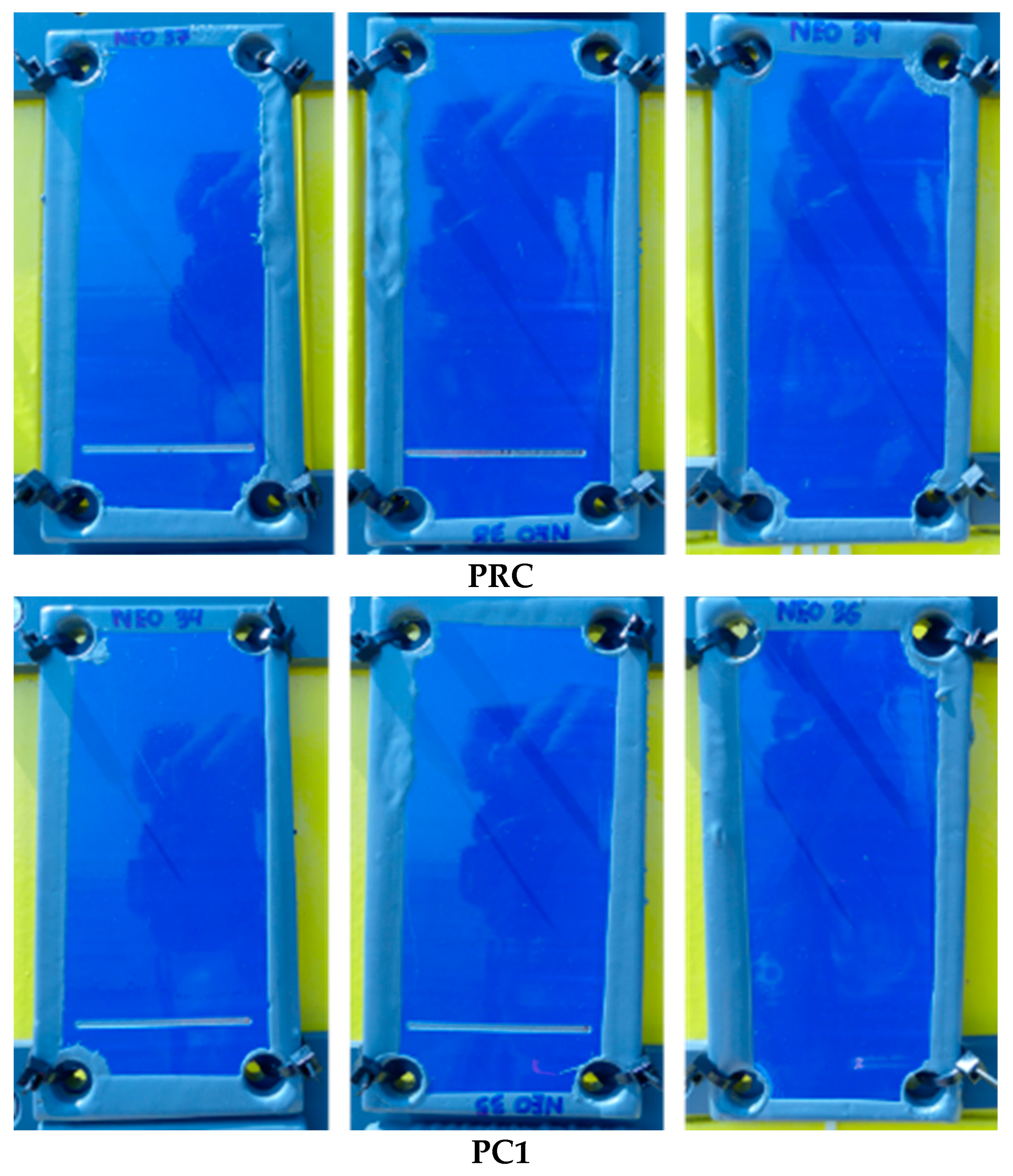
3.2. Characterization of Complete Three-Layer Coating Systems before Ageing Tests
3.3. Complete Coating System Anticorrosion Performance
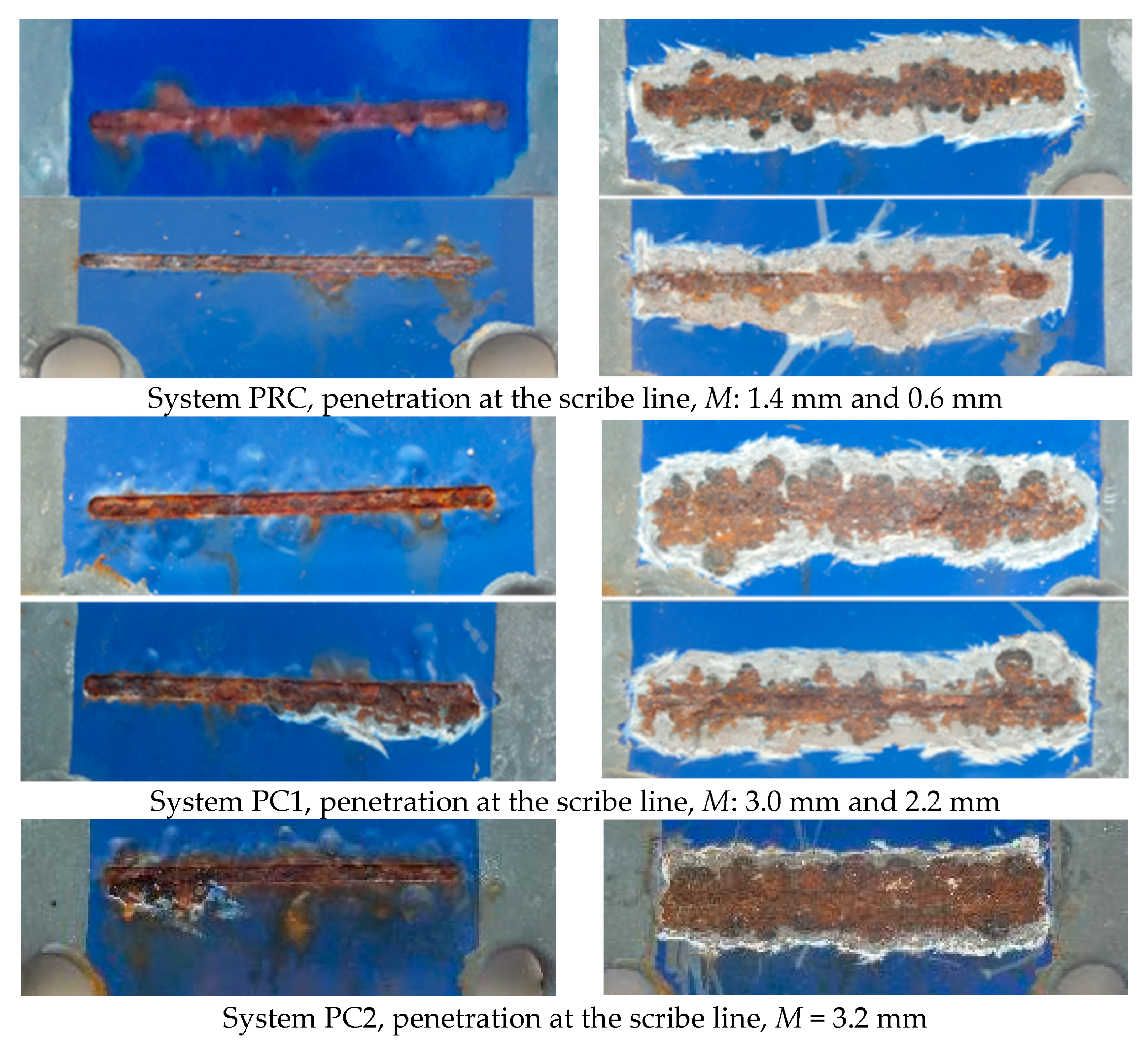
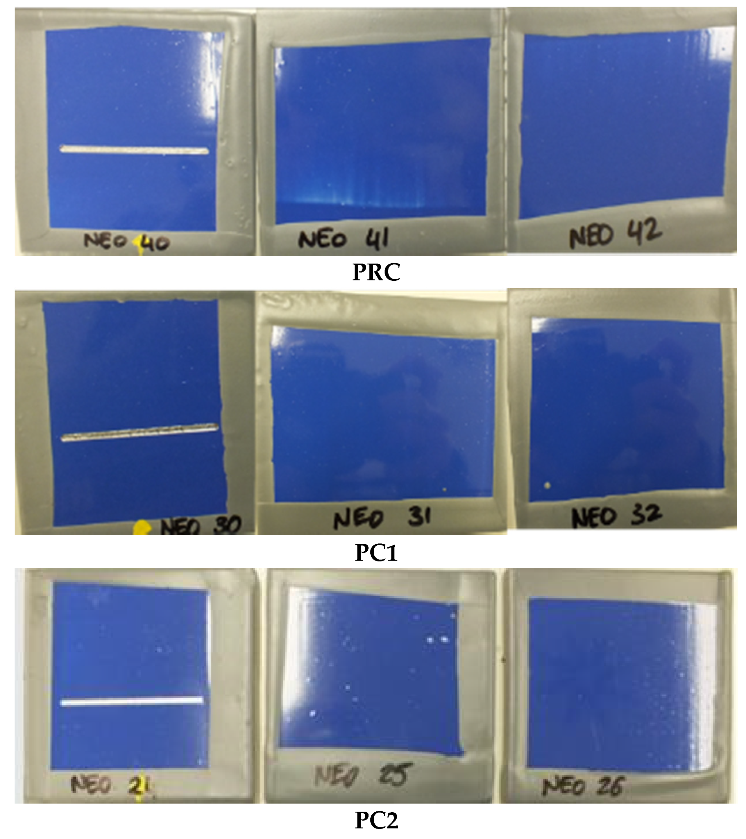
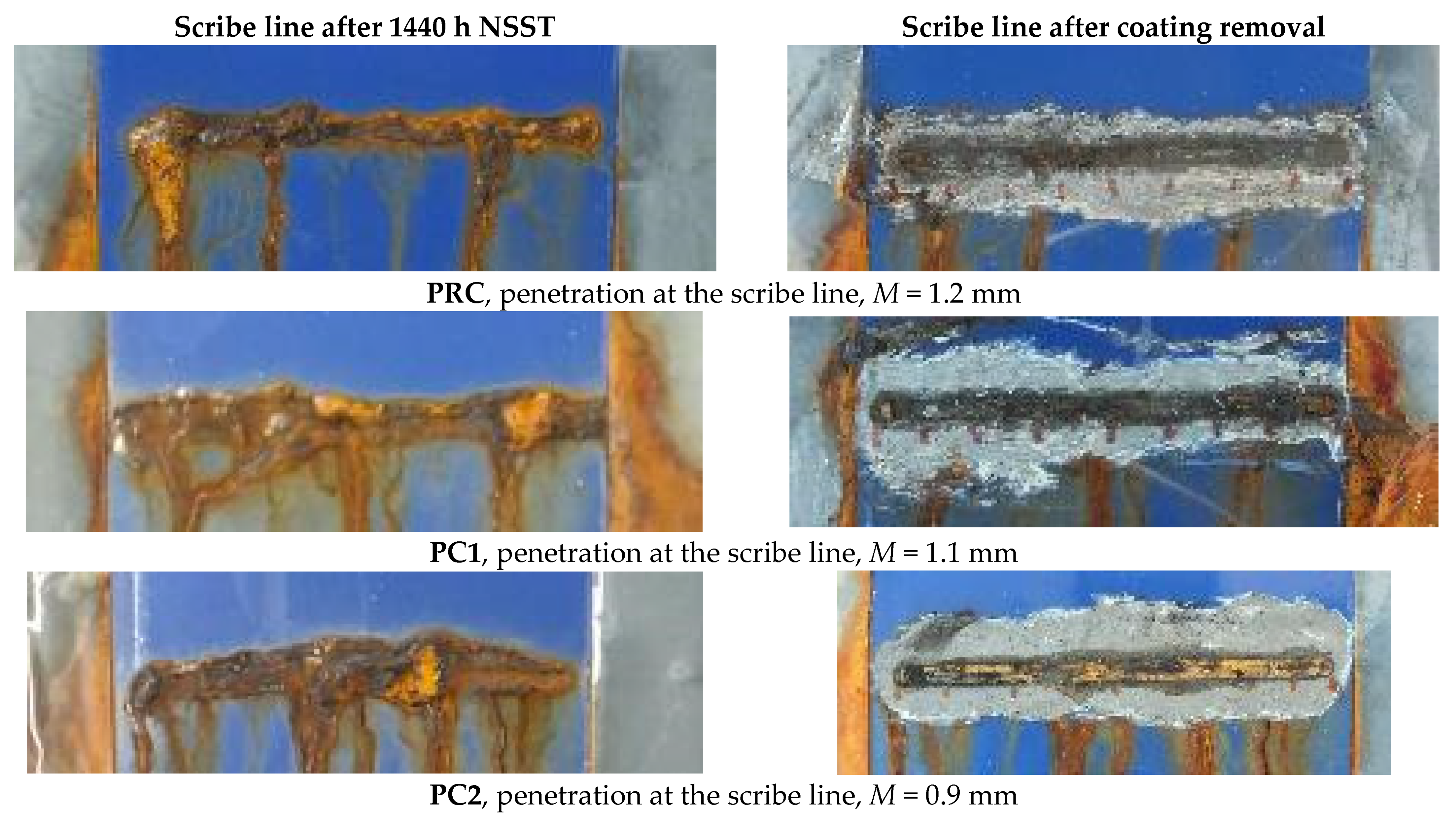
3.3.1. Laboratory Testing Results
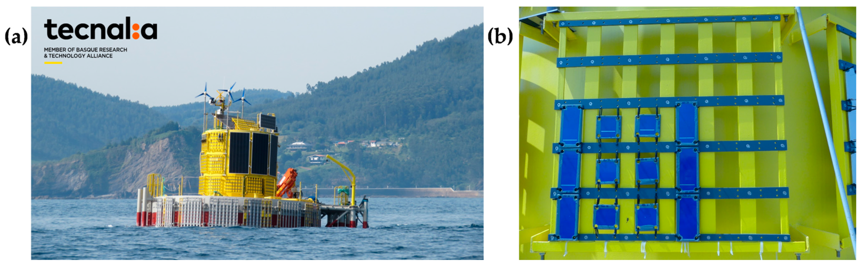
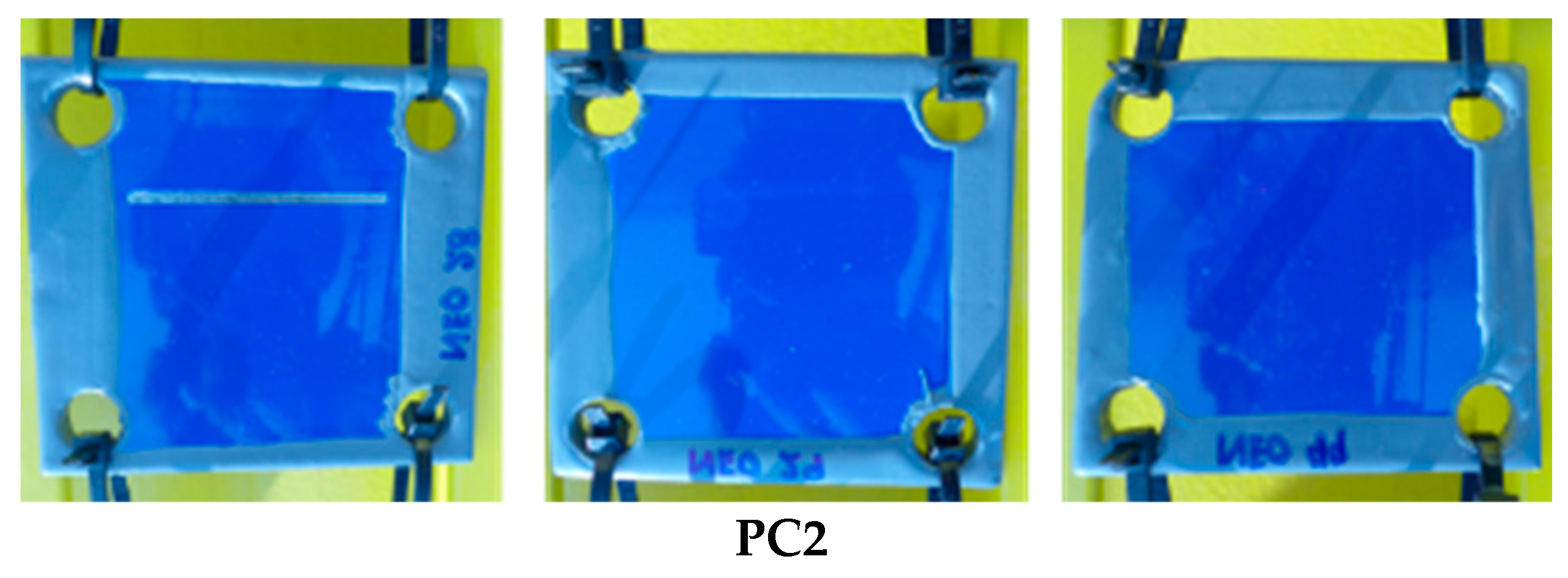
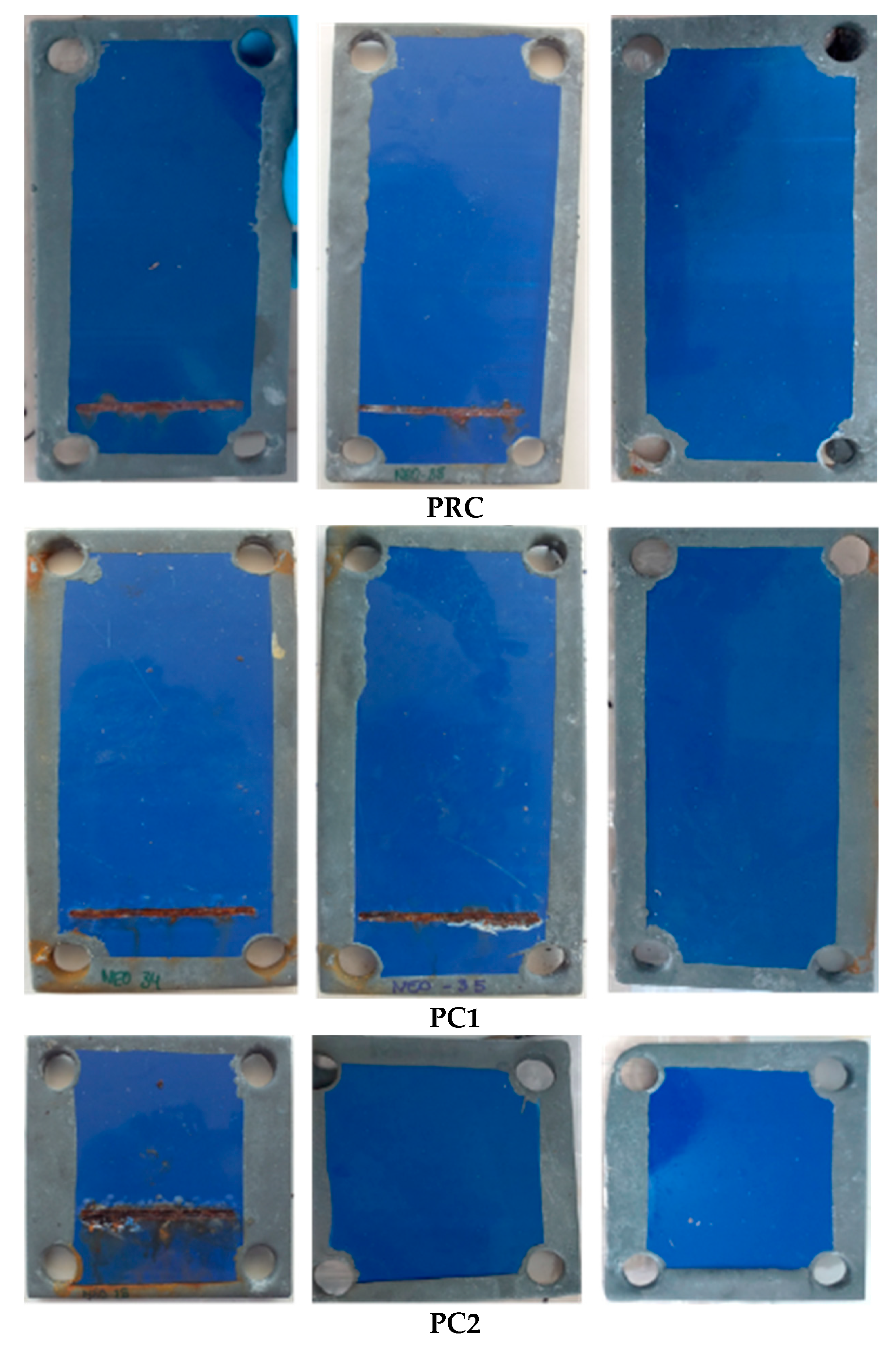
3.3.2. Field Exposure
4. Conclusions
Author Contributions
Funding
Institutional Review Board Statement
Informed Consent Statement
Data Availability Statement
Acknowledgments
Conflicts of Interest
References
- López-Ortega, A.B.R.A.J.L. Evaluation of Protective Coatings for High-Corrosivity Category Atmospheres in Offshore Applications. Materials 2019, 12, 1325. [Google Scholar] [CrossRef]
- Olajire, A.A. Recent Advances on Organic Coating System Technologies for Corrosion Protection of Offshore Metallic Structures. J. Mol. Liq. 2018, 269, 572–606. [Google Scholar] [CrossRef]
- Popoola, A.P.I.; Olorunniwo, O.E.; Ige, O.O. Corrosion Resistance through the Application of Anti-Corrosion Coatings. Dev. Corros. Prot. 2014, 13, 241–270. [Google Scholar]
- Funke, W. Organic Coatings in Corrosion Protection. In Surface Coatings—2; Wilson, A.D., Nicholson, J.W., Prosser, H.J., Eds.; Springer: Dordrecht, The Netherlands, 1988; pp. 107–135. ISBN 978-94-009-1351-6. [Google Scholar]
- ISO 12944-1; Paints and Varnishes—Corrosion Protection of Steel Structures by Protective Paint Systems—Part 1 General Introduction. International Organization for Standardization: Geneva, Switzerland, 2017.
- ISO 12944-2; Paints and Varnishes—Corrosion Protection of Steel Structures by Protective Paint Systems—Part 2 Classification of Environments. International Organization for Standardization: Geneva, Switzerland, 2017.
- ISO 12944-3; Paints and Varnishes—Corrosion Protection of Steel Structures by Protective Paint Systems—Part 3 Design Considerations. International Organization for Standardization: Geneva, Switzerland, 2017.
- ISO 12944-4; Paints and Varnishes—Corrosion Protection of Steel Structures by Protective Paint Systems—Part 4 Type of Surface and Surface Preparation. International Organization for Standardization: Geneva, Switzerland, 2017.
- ISO 12944-5; Paints and Varnishes—Corrosion Protection of Steel Structures by Protective Paint Systems—Part 5 Protective Paint Systems. International Organization for Standardization: Geneva, Switzerland, 2017.
- ISO 12944-6; Paints and Varnishes—Corrosion Protection of Steel Structures by Protective Paint Systems—Part 6 Laboratory Performance Test Methods. International Organization for Standardization: Geneva, Switzerland, 2018.
- ISO 12944-7; Paints and Varnishes—Corrosion Protection of Steel Structures by Protective Paint Systems—Part 7 Execution and Supervision of Paint Work. International Organization for Standardization: Geneva, Switzerland, 2017.
- ISO 12944-9; Paints and Varnishes—Corrosion Protection of Steel Structures by Protective Paint Systems—Part 9 Protective Paint Systems and Laboratory Performance Test Methods for Offshore and Related Structures. International Organization for Standardization: Geneva, Switzerland, 2018.
- Sørensen, P.A.; Kiil, S.; Dam-Johansen, K.; Weinell, C.E. Anticorrosive Coatings: A Review. J. Coat. Technol. Res. 2009, 6, 135–176. [Google Scholar] [CrossRef]
- Kumar, S.; Samal, S.K.; Mohanty, S.; Nayak, S.K. Recent Development of Biobased Epoxy Resins: A Review. Polym. Plast. Technol. Eng. 2018, 57, 133–155. [Google Scholar] [CrossRef]
- Jaini, M.; Namboothri, N. Boat Paint and Epoxy Fragments—Leading Contributors of Microplastic Pollution in Surface Waters of a Protected Andaman Bay. Chemosphere 2023, 312, 137183. [Google Scholar] [CrossRef]
- Turner, A.; Ostle, C.; Wootton, M. Occurrence and Chemical Characteristics of Microplastic Paint Flakes in the North Atlantic Ocean. Sci. Total Environ. 2022, 806, 150375. [Google Scholar] [CrossRef] [PubMed]
- Su, X.; Zhou, Z.; Liu, J.; Luo, J.; Liu, R. A Recyclable Vanillin-Based Epoxy Resin with High-Performance That Can Compete with DGEBA. Eur. Polym. J. 2020, 140, 110053. [Google Scholar] [CrossRef]
- Shibata, M.; Ohkita, T. Fully Biobased Epoxy Resin Systems Composed of a Vanillin-Derived Epoxy Resin and Renewable Phenolic Hardeners. Eur. Polym. J. 2017, 92, 165–173. [Google Scholar] [CrossRef]
- Stanzione, J.; La Scala, J. Recent Advances in Bio-Based Epoxy Resins and Bio-Based Epoxy Curing Agents. J. Appl. Polym. Sci. 2016, 133, 44103. [Google Scholar] [CrossRef]
- Pélissier, K.; Thierry, D. Powder and High-Solid Coatings as Anticorrosive Solutions for Marine and Offshore Applications? A Review. Coatings 2020, 10, 916. [Google Scholar] [CrossRef]
- Knudsen, O.Ø.; Forsgren, A. Corrosion Control through Organic Coatings; CRC Press: Boca Raton, FL, USA, 2017; ISBN 1498760732. [Google Scholar]
- Ellis, B. Chemistry and Technology of Epoxy Resins; Springer: Berlin/Heidelberg, Germany, 1993; ISBN 0751400955. [Google Scholar]
- Nikafshar, S.; Zabihi, O.; Hamidi, S.; Moradi, Y.; Barzegar, S.; Ahmadi, M.; Naebe, M. A Renewable Bio-Based Epoxy Resin with Improved Mechanical Performance That Can Compete with DGEBA. RSC Adv. 2017, 7, 8694–8701. [Google Scholar] [CrossRef]
- Sahoo, S.K.; Mohanty, S.; Nayak, S.K. Synthesis and Characterization of Bio-Based Epoxy Blends from Renewable Resource Based Epoxidized Soybean Oil as Reactive Diluent. Chin. J. Polym. Sci. 2015, 33, 137–152. [Google Scholar] [CrossRef]
- Flint, S.; Markle, T.; Thompson, S.; Wallace, E. Bisphenol A Exposure, Effects, and Policy: A Wildlife Perspective. J. Environ. Manag. 2012, 104, 19–34. [Google Scholar] [CrossRef] [PubMed]
- Aouf, C.; Nouailhas, H.; Fache, M.; Caillol, S.; Boutevin, B.; Fulcrand, H. Multi-Functionalization of Gallic Acid. Synthesis of a Novel Bio-Based Epoxy Resin. Eur. Polym. J. 2013, 49, 1185–1195. [Google Scholar] [CrossRef]
- Fan, Q.; Lu, T.; Deng, Y.; Zhang, Y.; Ma, W.; Xiong, R.; Huang, C. Bio-Based Materials with Special Wettability for Oil-Water Separation. Sep. Purif. Technol. 2022, 297, 121445. [Google Scholar] [CrossRef]
- Wu, X.; Zheng, S.; Bellido-Aguilar, D.A.; Silberschmidt, V.V.; Chen, Z. Transparent Icephobic Coatings Using Bio-Based Epoxy Resin. Mater. Des. 2018, 140, 516–523. [Google Scholar] [CrossRef]
- Entropy Resins. Available online: https://entropyresins.com/ (accessed on 30 October 2023).
- Wan, J.; Gan, B.; Li, C.; Molina-Aldareguia, J.; Kalali, E.N.; Wang, X.; Wang, D.Y. A Sustainable, Eugenol-Derived Epoxy Resin with High Biobased Content, Modulus, Hardness and Low Flammability: Synthesis, Curing Kinetics and Structure–Property Relationship. Chem. Eng. J. 2016, 284, 1080–1093. [Google Scholar] [CrossRef]
- Liu, X.Q.; Huang, W.; Jiang, Y.H.; Zhu, J.; Zhang, C.Z. Preparation of a Bio-Based Epoxy with Comparable Properties to Those of Petroleum-Based Counterparts. Express Polym. Lett. 2012, 6, 293–298. [Google Scholar] [CrossRef]
- Ge, X.; Chang, C.; Zhang, L.; Cui, S.; Luo, X.; Hu, S.; Qin, Y.; Li, Y. Conversion of Lignocellulosic Biomass Into Platform Chemicals for Biobased Polyurethane Application. Adv. Bioenergy 2018, 3, 161–213. [Google Scholar] [CrossRef]
- Saito, T.; Brown, R.H.; Hunt, M.A.; Pickel, D.L.; Pickel, J.M.; Messman, J.M.; Baker, F.S.; Keller, M.; Naskar, A.K. Turning Renewable Resources into Value-Added Polymer: Development of Lignin-Based Thermoplastic. Green Chem. 2012, 14, 3295–3303. [Google Scholar] [CrossRef]
- Kai, D.; Tan, M.J.; Chee, P.L.; Chua, Y.K.; Yap, Y.L.; Loh, X.J. Towards Lignin-Based Functional Materials in a Sustainable World. Green Chem. 2016, 18, 1175–1200. [Google Scholar] [CrossRef]
- Norgren, M.; Edlund, H. Lignin: Recent Advances and Emerging Applications. Curr. Opin. Colloid. Interface Sci. 2014, 19, 409–416. [Google Scholar] [CrossRef]
- Laurichesse, S.; Avérous, L. Chemical Modification of Lignins: Towards Biobased Polymers. Prog. Polym. Sci. 2014, 39, 1266–1290. [Google Scholar] [CrossRef]
- Chung, H.; Washburn, N.R. Chemistry of Lignin-Based Materials. Green Mater. 2013, 1, 137–160. [Google Scholar] [CrossRef]
- Fache, M.; Viola, A.; Auvergne, R.; Boutevin, B.; Caillol, S. Biobased Epoxy Thermosets from Vanillin-Derived Oligomers. Eur. Polym. J. 2015, 68, 526–535. [Google Scholar] [CrossRef]
- Nabipour, H.; Niu, H.; Wang, X.; Batool, S.; Hu, Y. Fully Bio-Based Epoxy Resin Derived from Vanillin with Flame Retardancy and Degradability. React. Funct. Polym. 2021, 168, 105034. [Google Scholar] [CrossRef]
- Jiang, H.; Sun, L.; Zhang, Y.; Liu, Q.; Ru, C.; Zhang, W.; Zhao, C. Novel Biobased Epoxy Resin Thermosets Derived from Eugenol and Vanillin. Polym. Degrad. Stab. 2019, 160, 45–52. [Google Scholar] [CrossRef]
- Available online: https://Specificpolymers.Com/Product/Dgeva/ (accessed on 11 April 2024).
- Suarez Vega, A.; Agustín-Sáenz, C.; Brusciotti, F.; Somers, A.; Forsyth, M. Effect of Lanthanum 4-Hydroxy Cinnamate on the Polymerisation, Condensation and Thermal Stability of Hybrid Sol–Gel Formulations. J. Solgel. Sci. Technol. 2020, 96, 91–107. [Google Scholar] [CrossRef]
- Suárez-Vega, A.; Agustín-Sáenz, C.; O’Dell, L.A.; Brusciotti, F.; Somers, A.; Forsyth, M. Properties of Hybrid Sol-Gel Coatings with the Incorporation of Lanthanum 4-Hydroxy Cinnamate as Corrosion Inhibitor on Carbon Steel with Different Surface Finishes. Appl. Surf. Sci. 2021, 561, 149881. [Google Scholar] [CrossRef]
- Šolić, T.; Marić, D.; Novoselović, D.; Samardžić, I. Optimization of Parameters for Protection of Materials by Primer Application. Coatings 2022, 12, 413. [Google Scholar] [CrossRef]
- Industrial and Marine High Resistance Epoxy-Zinc-System. Available online: https://www.bernardoecenarro.com/site/assets/files/5609/cap_naranja_03_b_30_en.pdf (accessed on 11 April 2024).
- Gardner, C.; Ford, K.-S.; Zahn, F.; Zahn, Z.; Bubble, H.; Ku, S. Viscosity Conversion Table. Available online: https://j.b5z.net/i/u/2119873/i/data/viscosity.pdf (accessed on 11 April 2024).
- ISO 19840; Paints and Varnishes-Corrosion Protection of Steel Structures by Protective Paint Systems-Measurement of, and Acceptance Criteria for, the Thickness of Dry Films on Rough Surfaces. International Organization for Standardization: Geneva, Switzerland, 2012.
- ISO 4624; Paints and Varnishes—Pull-Off Test for Adhesion. International Organization for Standardization: Geneva, Switzerland, 2023.
- ISO_9227; Corrosion Tests in Artificial—Salt Spray Tests. International Organization for Standardization: Geneva, Switzerland, 2017.
- Marinova, N.; Urbegain, A.; Benguria, P.; Travé, A.; Caracena, R. Evaluation of Anticorrosion Coatings for Offshore Wind Turbine Monopiles for an Optimized and Time-Efficient Coating Application. Coatings 2022, 12, 384. [Google Scholar] [CrossRef]
- ISO 4628-3; Paints and Varnishes—Evaluation of Degradation of Coatings—Designation of Quantity and Size of Defects, and of Intensity of Uniform Changes in Appearance. Part 3: Assessment of Degree of Rusting. International Organization for Standardization: Geneva, Switzerland, 2016.
- Lord, C. Common Mistakes That Lead to Adhesion Failure. 2013. Available online: https://exclusive.multibriefs.com/content/common-mistakes-that-lead-to-adhesion-failure/manufacturing (accessed on 11 April 2024).


| Primer | Technology | Resin | Sustainability |
|---|---|---|---|
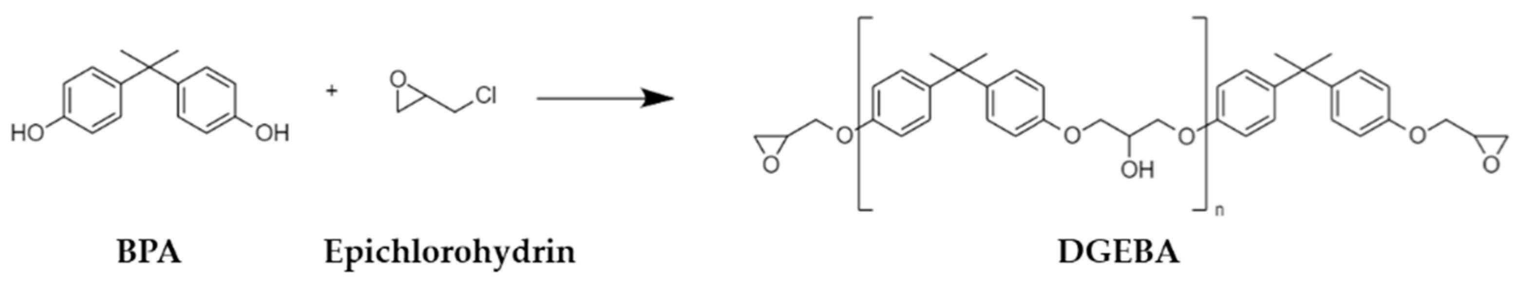
| PRC | Paint~70 μm | DGEBA | Petro-based |
| PC1 | Paint~70 μm | BIO-DGEBA | 30% bio-based |
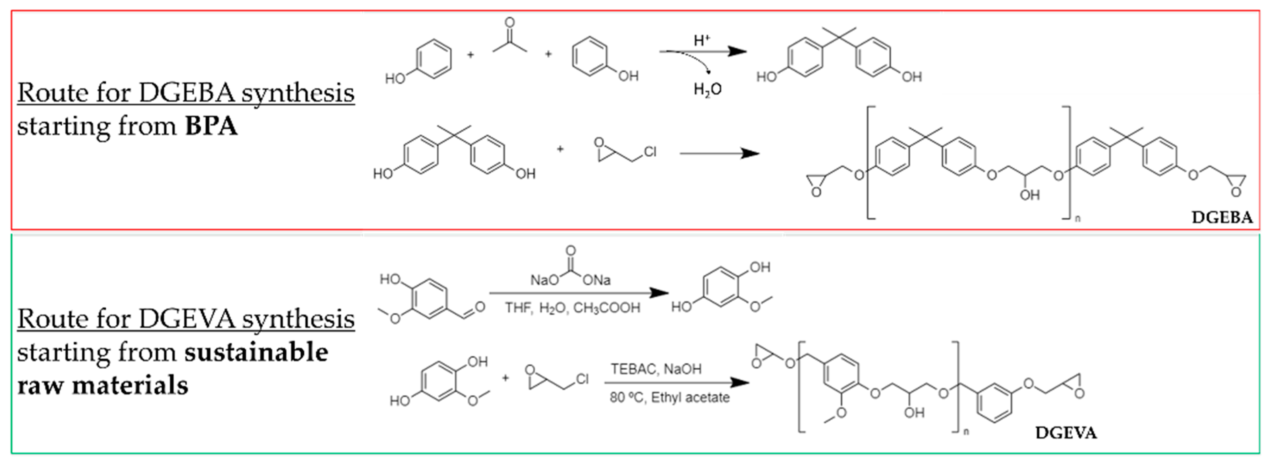
| PC2 | Hybrid sol–gel~5 μm | DGEVA | Thinner and BPA-free |
| Component A | wt. Max % |
|---|---|
| Xylene | 6 |
| Butan-1-ol | 3 |
| Entropy ER-ONE resin | 13 |
| Dodecyl and tetradecyl glycidyl ethers | 1 |
| Zinc powder | 74 |
| Zin oxide | 3 |
| Component B | |
| Entropy EH-ONF hardener |
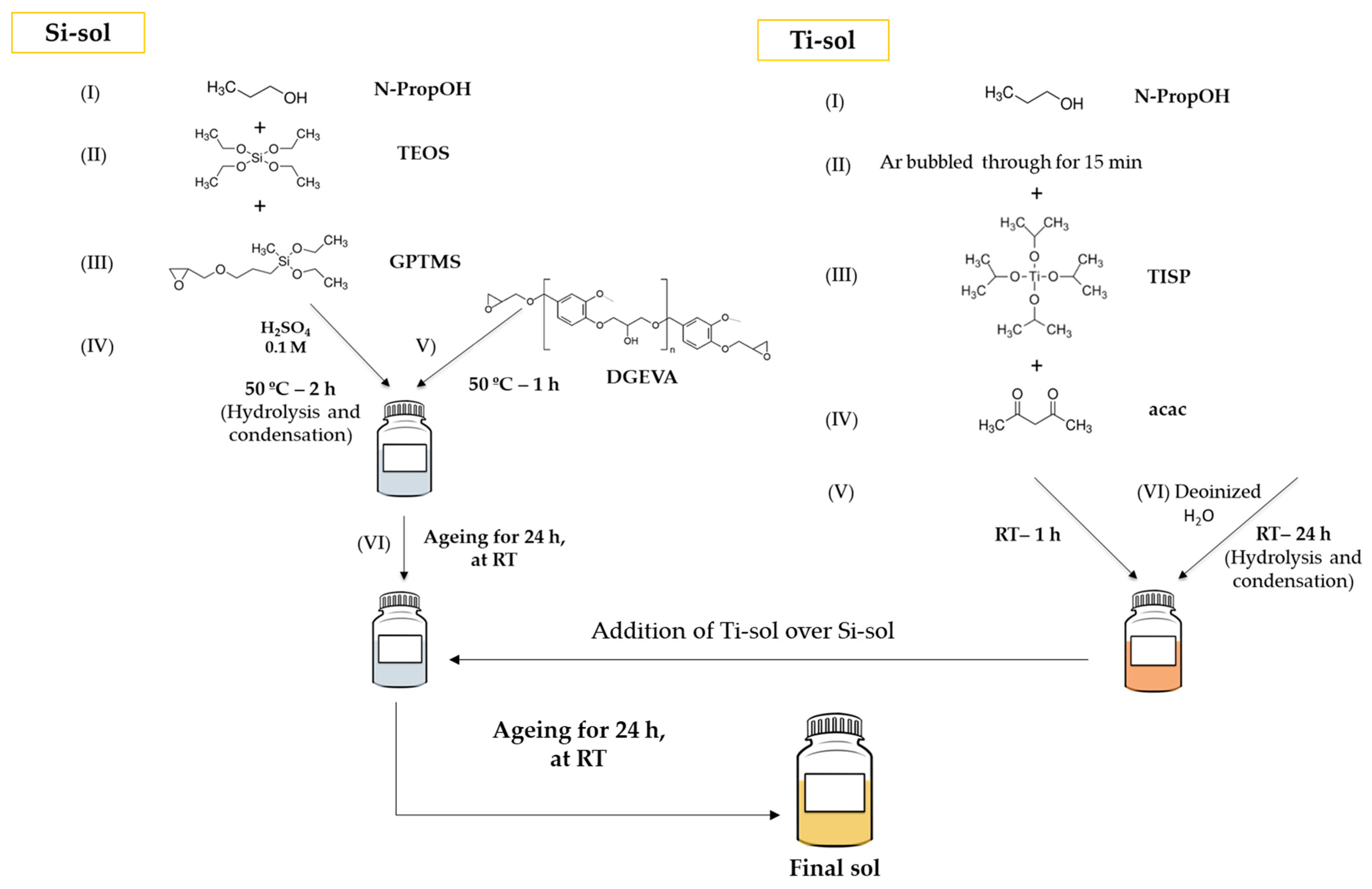
| Precursors’ Final Sol | Molar Ratios |
|---|---|
| TEOS | 1 |
| GPTMS | 3 |
| n-PropOH | 4 |
| H2SO4 0.1 M | 8 |
| DGEVA | 1 |
| TISP | 0.4 |
| acac | 0.4 |
| n-PropOH | 6.5 |
| Deionized H2O | 0.8 |
| Parameter | Value |
|---|---|
| Annual precipitation | 1500 mm/year |
| Mean interannual temperature | Min 10 °C, Max 16 °C |
| Average interannual temperature | 13 °C |
| Average insolation | 1825 h/year |
| Average annual wetting time (RH * > 80%, T > 0 °C) | 5960 h |
| Water temperature | Min 11 °C (January), Max 22 °C (August) |
| Significant wave height | Min 1.15 m, Max 9.62 m, Average 1.67 m |
| Average salinity | 35 USP. |
| Average dissolved O2 | 6 mL/L |
| Average transmittance | 88% |
| Primer | Average Thickness ± Standard Deviation (µm) |
|---|---|
| PRC | 73 ± 3 |
| PC1 | 76 ± 3 |
| PC2 | 4.9 ± 0.2 |
| Coating System | Average Thickness ± Standard Deviation (µm) |
|---|---|
| PRC | 235 ± 8 |
| PC1 | 235 ± 15 |
| PC2 | 193 ± 6 |
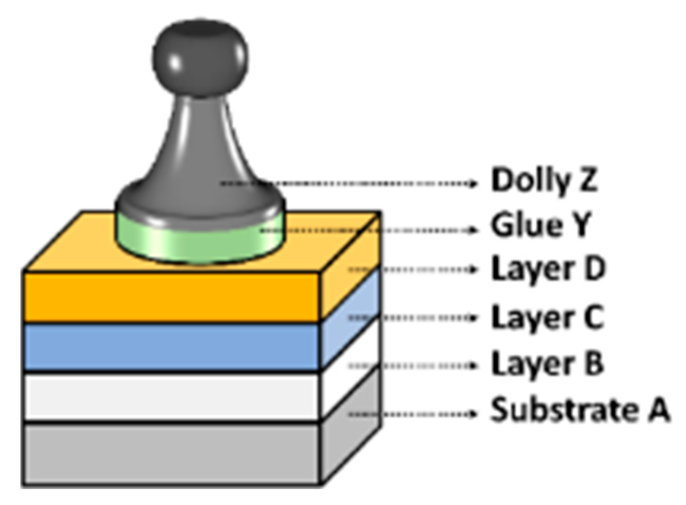
| Coating System | New Panels (MPa) | After 1440 NSST (MPa) | After 10 Months of Field Exposure (MPa) |
|---|---|---|---|
| PRC | 19 ± 0 | 10 ± 2 | 15 ± 2 |
| PC1 | 18 ± 1 | 7 ± 1 | 14 ± 2 |
| PC2 | 16 ± 1 | 13 ± 4 | 15 ± 2 |
Disclaimer/Publisher’s Note: The statements, opinions and data contained in all publications are solely those of the individual author(s) and contributor(s) and not of MDPI and/or the editor(s). MDPI and/or the editor(s) disclaim responsibility for any injury to people or property resulting from any ideas, methods, instructions or products referred to in the content. |
© 2024 by the authors. Licensee MDPI, Basel, Switzerland. This article is an open access article distributed under the terms and conditions of the Creative Commons Attribution (CC BY) license (https://creativecommons.org/licenses/by/4.0/).
Share and Cite
Suárez-Vega, A.; Berriozabal, G.; Urbegain, A.; Minudri, D.; Somers, A.; Forsyth, M.; Caracena, R.; Marinova, N. Exploring Sustainable Coating Solutions for Applications in Highly Corrosive Environments. Coatings 2024, 14, 521. https://doi.org/10.3390/coatings14050521
Suárez-Vega A, Berriozabal G, Urbegain A, Minudri D, Somers A, Forsyth M, Caracena R, Marinova N. Exploring Sustainable Coating Solutions for Applications in Highly Corrosive Environments. Coatings. 2024; 14(5):521. https://doi.org/10.3390/coatings14050521
Chicago/Turabian StyleSuárez-Vega, Ana, Gemma Berriozabal, Aiala Urbegain, Daniela Minudri, Anthony Somers, Maria Forsyth, Raúl Caracena, and Nevena Marinova. 2024. "Exploring Sustainable Coating Solutions for Applications in Highly Corrosive Environments" Coatings 14, no. 5: 521. https://doi.org/10.3390/coatings14050521