Communication

A Novel Technique for the Deposition of Bismuth Tungstate onto Titania Nanoparticulates for Enhancing the Visible Light Photocatalytic Activity

1
Surface Engineering Group, Manchester Metropolitan University, Manchester, M1 5GD, UK
2
School of Science and the Environment, Manchester Metropolitan University, Manchester, M1 5GD, UK
*
Author to whom correspondence should be addressed.
Coatings 2016, 6(3), 29; https://doi.org/10.3390/coatings6030029
Submission received: 17 June 2016 / Revised: 12 July 2016 / Accepted: 19 July 2016 / Published: 21 July 2016

Abstract

:
A novel powder handling technique was used to allow the deposition of bismuth tungstate coatings onto commercial titanium dioxide photocatalytic nanoparticles. The coatings were deposited by reactive pulsed DC magnetron sputtering in an argon/oxygen atmosphere. The use of an oscillating bowl with rotary particle propagation, positioned beneath two closed-field planar magnetrons, provided uniform coverage of the titania particle surfaces. The bismuth/tungsten atomic ratio of the coatings was controlled by varying the power applied to each target. The resulting materials were characterized by X-ray diffraction, energy-dispersive X-ray spectroscopy (EDX), Brunauer–Emmett–Teller (BET) surface area measurements, transmission electron microscopy (TEM), and UV-visible diffuse reflectance spectroscopy. Photocatalytic properties under visible light irradiation were assessed using an acetone degradation test. It was found that deposition of bismuth tungstate onto titania nanoparticles resulted in significant increases in visible light photocatalytic activity, compared to uncoated titania. Of the coatings studied, the highest photocatalytic activity was measured for the sample with a Bi/W atomic ratio of 2/1.

1. Introduction

In the past few decades, photocatalysis is often reported as a process of choice for the degradation of organic pollutants and surface disinfection. Of the photocatalytic materials known, titanium dioxide, or titania, in anatase form is typically a photocatalyst of choice for various environmental remediation processes due to its low cost, chemical stability, and low toxicity. Titanium dioxide in the form of nanoparticles is much more efficient as a photocatalyst, compared to bulk material, as it provides much higher surface area and therefore higher area of contact with the pollutant. Degussa P25 is reportedly the most widely used photocatalytic material to date. However, despite all the above, TiO2 possesses some remarkable drawbacks, which limits its potential applications. For example, the relatively high band gap value of TiO2 (3.2 eV for the anatase phase) means that only the UV part of the spectrum (around 4% of sunlight) can be used for its activation. Moreover, titanium dioxide is characterized with low separation efficiency of the photoexcited charge carriers, which makes its use a rather challenging task for real industrial waste management. Various modifications of titanium dioxide have been proposed to date, with doping with transition metals [1,2,3] and non-metallic [3,4] elements being the most conventional methods. However, the photocatalytic activity of the modified materials is often not comparable with that of unmodified TiO2 due to higher rates of photogenerated charge carrier recombination.
Coupling titanium dioxide with narrow band semiconductors is a method being widely described in publications recently; it typically results in enhancement of the optical adsorption abilities of the material, as well as improved separation of photogenerated charge carriers. Thus, titanium dioxide coupled with such materials, as CdS [5], WO3 [6], Cu2O [7], etc has been reported. Bismuth tungstate (Bi2WO6) is gaining increasing popularity as a narrow band gap semiconductor that exhibits good photocatalytic properties under visible light irradiation [8,9]. Several successful attempts to couple bismuth tungstate with titanium dioxide have been reported recently [10,11,12]. The main preparation methods described are hydrothermal methods [10,13,14,15], electrospinning [11,16], dip-coating [17], etc. The present study describes the deposition of bismuth tungstate onto titania powders by pulsed DC reactive magnetron sputtering in a single stage process.
Magnetron sputtering is the process of choice for the deposition of a wide range of industrially important functional films [18]. Substrates range in size from 6m × 3m “jumbo” sheets of architectural glazing to microelectronic components. However, the “line of sight” nature of the process makes it generally unsuited to coating particulates. Sophisticated substrate jigging, planetary rotation, and multiple magnetron systems allow 3D components to be uniformly coated, but the same approach cannot be applied to powders. Rotating drums have been used to tumble small components during the sputter deposition of corrosion resistant coatings to avoid the need for fixturing [19]. Abe and co-workers have also published details of a drum-based system for RF sputtering of e.g., Pt coatings onto small charges (2g) of silica particles [20,21], and Poelman, et al. describe a rotating drum for depositing vanadia-based catalysts for the oxidative dehydrogenation of propane [22]. Schmid has published several papers on the use of angled rotating cups positioned under magnetrons, particularly for coating glass microspheres with refractory metals [23,24]. Yu, et al. also use an ultrasonic vibration generator in a similar manner to tumble fly-ash cenosphere particles during the deposition of titania [25]. The present authors have developed an alternative approach to those described above, which is capable of depositing metallic and ceramic coatings onto larger charges (several 10s of grams, depending on particle density) in a single stage process.

2. Materials and Methods

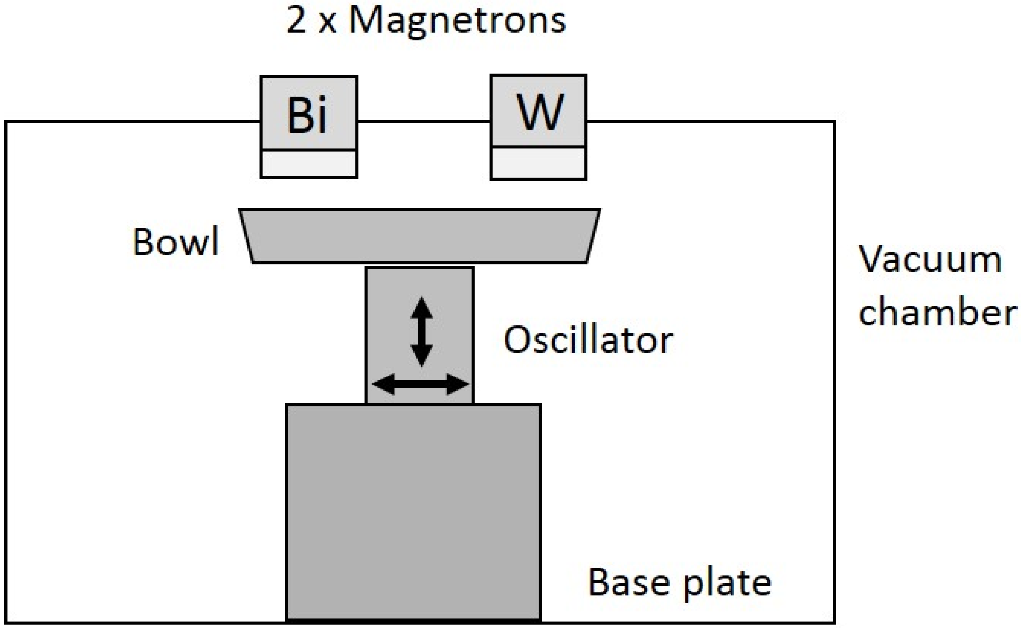
2.1. Oscillator Description

The oscillating mechanism used to manipulate the powder came from a vibrating bowl feeder system designed to feed small components from a bowl, around a spiral track at the edge of the bowl and out onto a production line. The original bowl was replaced with a plain flat bottomed bowl of 450 mm in diameter positioned under a pair of co-planar magnetrons which enabled sputtering from two targets (Bi and W in our case) simultaneously. The charge of powder is placed in the bowl and the whole assembly was installed in the vacuum chamber directly underneath the magnetrons, giving a target to substrate separation of 120 mm. This arrangement is shown schematically in Figure 1. The bowl oscillates vertically at 50 Hz, but springs connected between the electromagnet and the base plate are designed to also impart a lateral twisting moment to the oscillation. The resulting motion causes particles in the bowl to roll or hop in a circular path around the bottom of the bowl and, thus, over time all surfaces of the particles are exposed to the coating flux. Coating uniformity and thickness are functions of run time, target power and deposition rate (material arrival rate parameters), particle size and shape, and the charge of powder in the bowl (surface area parameters). This system is distinctly different to those reported elsewhere, since the particles in our system are not only oscillated vertically, but also tumble horizontally around the bowl.

2.2. Deposition Conditions

The bismuth tungstate coatings were deposited in a vacuum coating system that included two 300mm × 100mm planar unbalanced type II magnetrons installed through the chamber roof facing the oscillator bowl in a closed field sputter-down configuration. The bismuth target was fitted to one of the magnetrons, and the tungsten target to the other one (both targets were 99.5% pure and bonded to copper backing plates). The targets were sputtered in reactive mode in an argon/oxygen atmosphere, at a partial pressure of 0.4 Pa. The flow of gases was controlled using mass-flow controllers (10 sccm of Ar and 20 sccm of O2). The magnetrons were powered in pulsed DC mode using a dual channel Advanced Energy Pinnacle Plus (Fort Collins, CO, USA) power supply; a pulse frequency of 100 kHz and duty cycle of 50% (synchronous mode) were used for all the deposition runs. The powers applied to the targets were varied to produce a range of Bi/W contents in the films (100–200 W for Bi and 400–450 W for W). A 10 g charge of titania particles was used (PC500 TiO2 from Crystal Global, Grimsby, UK with individual particle sizes of 5–10 nm). Deposition time was 1 hour for all the coatings studied. Substrate temperature during the deposition was estimated as 60–65 °C.

2.3. Analytical Techniques

The X-ray diffraction analysis of the samples was carried out using a Panalytical Xpert diffractometer with CuKa1 radiation at 0.154 nm over a scan range from 20° to 70° 2θ; the accelerating voltage and applied current were 40 kV and 30 mA, respectively. The composition of the powders was determined using EDX (EDAX–Trident on a Zeiss Supra 40 FEGSEM, Edax Co., Mahwah, NJ, USA). The specific surface areas of the materials were determined with Brunauer–Emmett–Teller (BET) surface area measurements using a Micromeritics ASAP 2020 system (Micromeritics Instrument Corporation, Norcross, GA, USA), where samples were degassed for 12 h at 300 °C prior to analysis and surface areas were calculated from nitrogen adsorption data in the range of relative pressures between 0.05 and 0.3 using the BET model. Optical properties of the materials were determined from UV-visible diffuse reflectance spectra recorded with an Ocean Optics USB4000 spectrometer equipped with a diffuse reflectance probe (Ocean Optics, Dunedin, FL, USA). Selected samples have also been analysed with a TEM (FEI Tecnai FEGTEM Field Emission gun TEM/STEM fitted with HAADF detector, FEI, Cambridge, UK).

2.4. Evaluation of Photocatalytic Activity

The assessment of photocatalytic properties was carried out using an acetone degradation test in a purpose-built reaction cell equipped with a quartz glass window. The fixed amount of photocatalyst (1 g) was evenly spread over a 55 mm glass plate and placed into the reaction cell; 1 mL of liquid acetone was introduced to the cell with a syringe. As carbon dioxide is one of the products of photocatalytic acetone degradation, a CO2 detector (Vaisala CARBOCAP® carbon dioxide meter, Vaisala, Vantaa, Finland, used with a Vaisala GM70 2000 ppm probe) was incorporated into the reaction cell to measure CO2 concentration over time. The reaction cell was kept in the dark for 30 min at room temperature to reach the adsorption-desorption equilibrium, then irradiation with the simulated visible light source (Sunlite 8 W white LED, combined with a 395 nm long pass filter from Knight Optical) for a total time of 1 h. The emission spectrum of the irradiation source used for photocatalytic testing was recorded with Ocean Optics USB400 spectrometer and presented in Figure 2. Uncoated PC500 titania was analysed with all the techniques above for comparison purposes.

3. Results and Discussion

3.1. Samples Overview and Composition

The overview of the samples studied is given in the Table 1.
According to the results of EDX mapping (images of the EDX maps are not given here), bismuth and tungsten were evenly distributed on the surface of the titania particles, which confirms the efficiency of the method proposed for coating the nanoparticles.
As can be seen from the data presented in Table 1, variation of the power applied to the bismuth and tungsten targets resulted in variations in coating composition, in a similar manner to the deposition of bismuth complex oxides onto flat substrates reported earlier [26,27]. BET surface area measurements of PC500 titania were in good agreement with the manufacturer’s information of 350 m2/g. BET surface areas of the coated samples showed reductions in the surface area with deposition of bismuth tungstate onto the titania particles, as the ratio of Bi/W decreased, i.e., as the W content increased. This can be explained by the observed increasing agglomeration of the particles as a function of tungsten content.

3.2. XRD

The XRD spectra of the coatings are given in Figure 3. It can be seen that only peaks corresponding to the anatase TiO2 appear on the spectra (JCPDS: 21–1272). This is most likely due to the fact that the content of bismuth tungstate is rather low, and it is under the sensitivity threshold of XRD. No significant changes in crystallinity of TiO2 occurred after deposition of bismuth tungstate, with (101) remaining the predominant crystal plane. Broad diffraction peaks were observed, which is evidence that that crystal grains are in the nanoscale range. Crystallite sizes listed in Table 1 were estimated using the Scherrer equation and varied in the range 7–10 nm (as given in Table 1). Crystallite sizes did not change significantly with bismuth tungstate deposition, however it should be noted that they were calculated based on the anatase (101) titania peak only, therefore these values are given here just for estimation purposes.

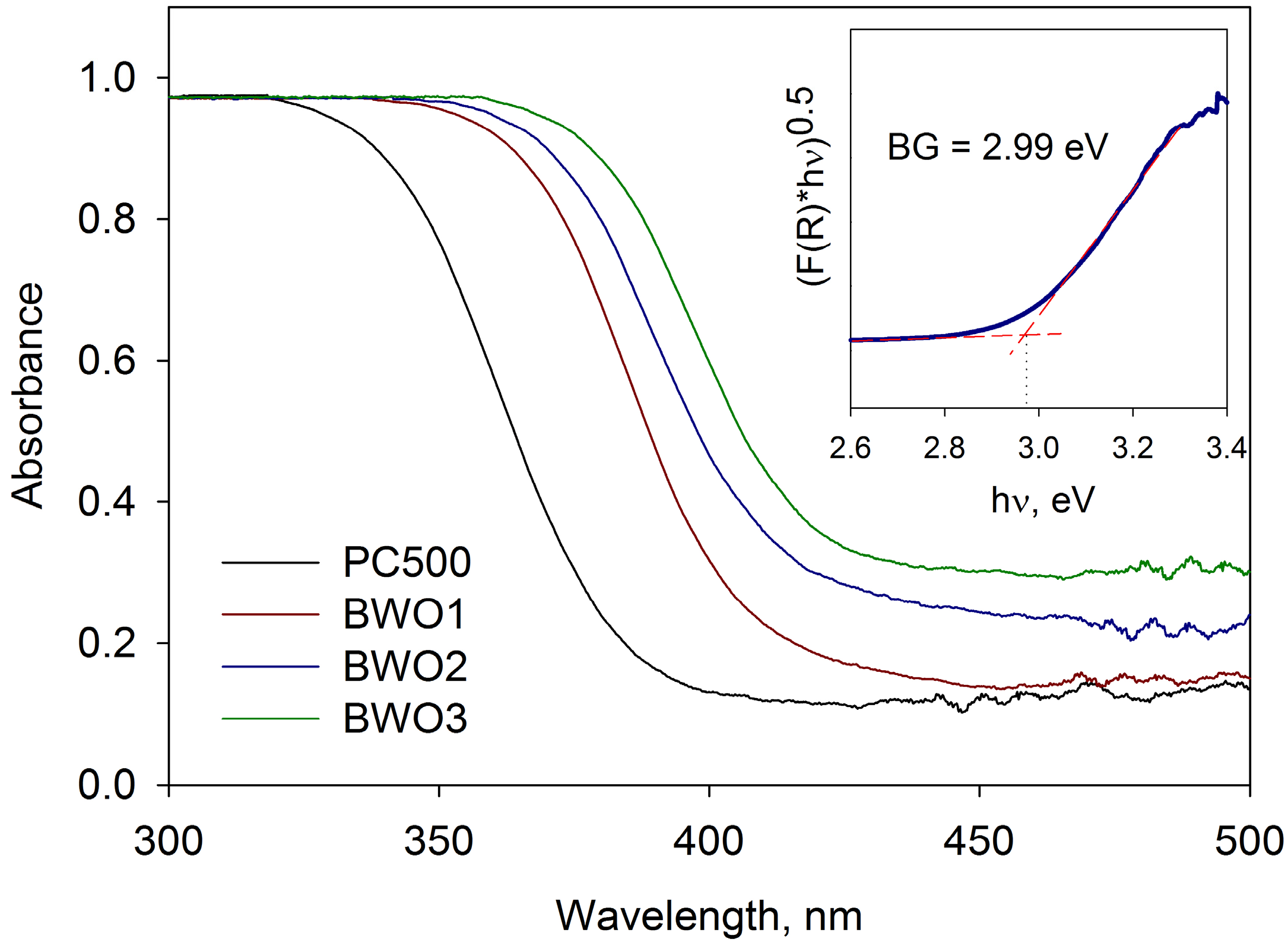
3.3. Band Gap Calculation

The absorbance data of the samples are plotted in Figure 4. The band gaps values were estimated using Tauc plots of [F(R) hυ]0.5 versus , where F(R) is the Kubelka-Munk function, and is the incident photon energy. The calculated band gaps of the powders are given in the Table 1. As expected, uncoated PC500 titania exhibits absorption in the UV range only (below 395 nm), which is in good agreement with literature data on its band gap (typically reported as 3.2 eV [28]), while for bismuth tungstate-coated particles the absorption is clearly shifted towards the visible range. The highest red shift is observed for the sample BWO3. Therefore, all of the coated samples demonstrated band gap values sufficient to be activated with the light source chosen.

3.4. TEM Results

The microstructures of plain and coated titania particles were further studied by TEM and high resolution (HR) TEM. Representative examples of TEM and high resolution TEM images of coated and uncoated titania powders are presented in Figure 5. Figure 5a,c show the typical TEM images of uncoated PC500 titania and coated sample BWO2 particles, respectively. It is obvious from the image that titania particles are agglomerated for both coated and uncoated samples; titania agglomerates in Figure 5c are coated uniformly. Lattice fringes can be clearly observed on both of the HRTEM images (Figure 5b,d), and they were used for identification of the crystal planes of the samples. On Figure 5b, the fringe spacing was estimated as 0.35 nm, which corresponds to the (101) plane of anatase titania, and is in good agreement with XRD data presented in Figure 3. Fringe spacing on Figure 5d was ca. 0.315 nm, which can be attributed to (131) plane of bismuth tungstate Bi2WO6 (JCPDS: 39256) [10]. It is worth noting that the as-deposited bismuth tungstate was in crystalline form, without any further thermal treatment applied to the samples.

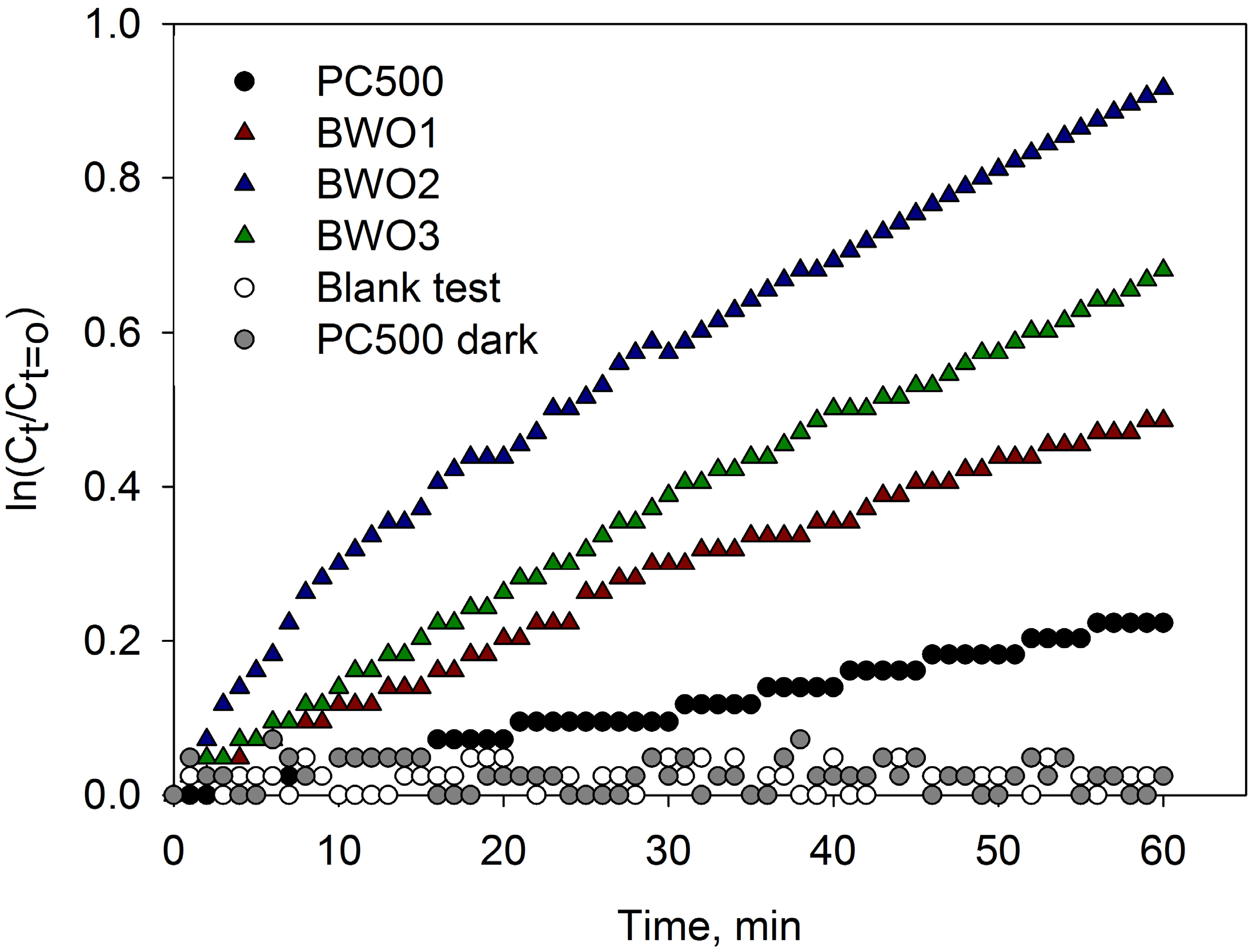
3.5. Photocatalytic Activity Measurement

The photocatalytic activity of the coated and uncoated titania particles under the visible light source (λ > 395 nm) was evaluated using the acetone degradation test. The photocatalytic decomposition process of acetone can be summarised using the following equation:
C 3 H 6 O + 4 O 2 TiO 2 > 3.2 eV   3 CO 2 + 3 H 2 O
Therefore, CO2 concentration was recorded as an indication of photocatalytic activity over a 1-hour period. The first order linear relationship was revealed by plotting ln(Ct/Ct=0) as a function of irradiation time, where Ct=0 is the initial concentration of carbon dioxide, and Ct is the CO2 concentration at the irradiation time t. The values of the rate constants calculated per unit of surface area are given in the Table 1, and the CO2 evolution kinetics are presented in Figure 6. The results of the blank test (no photocatalyst) and TiO2 PC500 in dark conditions are given for reference purpose.
It is clear from Figure 6 that the deposition of bismuth tungstate onto titanium dioxide particles significantly increased photocatalytic activity under visible light. Not surprisingly, the photocatalytic activity of PC500 titania in this case was very low, due to the relatively high value of its band gap. Of the samples studied, the highest level of activity was recorded for the coating BWO2, nevertheless the band gap value of this sample was not the lowest of those tested here. The lower photocatalytic activity of sample BWO3, despite its lower band gap, can possibly be explained by the presence of amorphous tungsten in this tungsten-rich sample, which could inhibit the photoactivity [26].
It should be noted that, at this stage of the work, it is not known whether the observed increase of visible light photocatalytic activity is solely due to the red shift of the band gap and more efficient charge carrier separation of the composite material, rather than the intrinsic photocatalytic properties of bismuth tungstate that are often reported. Further studies aimed at obtaining a better understanding of photocatalytic degradation mechanisms and coating optimisation are currently in progress.

4. Conclusions

In summary, the present work shows that the new coating technique described here is suitable for functionalizing photocatalytic nanoparticulates by magnetron sputtering. Bismuth tungstate coatings were successfully deposited onto a commercial titania photocatalyst; variation of target powers allowed deposition of crystalline coatings of different compositions. The use of an oscillating bowl as a substrate holder enables uniform distribution of bismuth tungstate coatings on the titania powders. Deposition of bismuth tungstate resulted in significant increases in visible light photocatalytic activity compared to unmodified titania.

Acknowledgments

Acknowledgement to Leeds EPSRC Nanoscience and Nanotechnology Research Equipment Facility (LENNF) for conducting the TEM analysis of the coatings.

Author Contributions

The process design, experimental work, and writing of the first draft of the manuscript were all carried out by Marina Ratova. Peter J. Kelly and Glen T. West supervised every step of the entire work. Lubomira Tosheva performed BET analysis of the samples.

Conflicts of Interest

The authors declare no conflict of interest.

References

  1. Ratova, M.; Kelly, P.J.; West, G.T.; Iordanova, I. Enhanced properties of magnetron sputtered photocatalytic coatings via transition metal doping. Surf. Coat. Tech. 2013, 228, S544–S549. [Google Scholar] [CrossRef]
  2. Ratova, M.; West, G.; Kelly, P. Optimization studies of photocatalytic tungsten-doped titania coatings deposited by reactive magnetron co-sputtering. Coatings 2013, 3, 194–207. [Google Scholar] [CrossRef]
  3. Rehman, S.; Ullah, R.; Butt, A.M.; Gohar, N.D. Strategies of making TiO2 and ZnO visible light active. J. Hazard. Mater. 2009, 170, 560–569. [Google Scholar] [CrossRef] [PubMed]
  4. Asahi, R.; Morikawa, T.; Ohwaki, T.; Aoki, K.; Taga, Y. Visible-light photocatalysis in nitrogen-doped titanium oxides. Science 2001, 293, 269–271. [Google Scholar] [CrossRef] [PubMed]
  5. Wang, Z.; Xu, Q.; Meng, T.; Ren, T.; Chen, D. Preparation and characterization of CdS/TiO2-Mt composites with enhanced visible light photocatalytic activity. Energy Environ. Focus 2015, 4, 149–156. [Google Scholar]
  6. Yamin, Y.; Keller, N.; Keller, V. WO3-modified TiO2 nanotubes for photocatalytic elimination of methylethylketone under UVA and solar light irradiation. J. Photoch. Photobiol. A 2012, 245, 43–57. [Google Scholar] [CrossRef]
  7. Zhang, J.F.; Wang, Y.; Yu, C.P.; Shu, X.; Jiang, L.; Cui, J.W.; Chen, Z.; Xie, T.; Wu, Y.C. Enhanced visible-light photoelectrochemical behaviour of heterojunction composite with Cu2O nanoparticles-decorated TiO2 nanotube arrays. New J. Chem. 2014, 38, 4975–4984. [Google Scholar] [CrossRef]
  8. Saison, T.; Gras, P.; Chemin, N.; Chanéac, C.; Durupthy, O.; Brezová, V.; Colbeau-Justin, C.; Jolivet, J.-P. New insights into Bi2WO6 properties as a visible-light photocatalyst. J. Phys. Chem. C 2013, 117, 22656–22666. [Google Scholar] [CrossRef]
  9. Zhang, L.-W.; Wang, Y.-J.; Cheng, H.-Y.; Yao, W.-Q.; Zhu, Y.-F. Synthesis of porous Bi2WO6 thin films as efficient visible-light-active photocatalysts. Adv. Mater. 2008, 21, 1286–1290. [Google Scholar] [CrossRef]
  10. Deng, F.; Liu, Y.; Luo, X.; Chen, D.; Wu, S.; Luo, S. Enhanced photocatalytic activity of Bi2WO6/TiO2 nanotube array composite under visible light irradiation. Sep. Purif. Technol. 2013, 120, 156–161. [Google Scholar] [CrossRef]
  11. Zhao, G.; Liu, S.; Lu, Q.; Xu, F.; Sun, H.; Yu, J. Synthesis of TiO2/Bi2WO6 nanofibers with electrospinning technique for photocatalytic methyl blue degradation. J. Sol-Gel Sci. Technol. 2013, 66, 406–412. [Google Scholar] [CrossRef]
  12. Murcia-López, S.; Hidalgo, M.C.; Navío, J.A. Photocatalytic activity of single and mixed nanosheet-like Bi2WO6 and TiO2 for rhodamine b degradation under sunlike and visible illumination. Appl. Catal. A 2012, 423–424, 34–41. [Google Scholar] [CrossRef]
  13. Murcia-López, S.; Hidalgo, M.C.; Navío, J.A. Degradation of rhodamine b/phenol mixtures in water by sun-like excitation of a Bi2WO6–TiO2 photocatalyst. Photochem. Photobiol. 2013, 89, 832–840. [Google Scholar] [CrossRef] [PubMed]
  14. Xu, J.; Wang, W.; Sun, S.; Wang, L. Enhancing visible-light-induced photocatalytic activity by coupling with wide-band-gap semiconductor: A case study on Bi2WO6/TiO2. Appl. Catal. B 2012, 111–112, 126–132. [Google Scholar] [CrossRef]
  15. Hou, Y.-F.; Liu, S.-J.; Zhang, J.-H.; Cheng, X.; Wang, Y. Facile hydrothermal synthesis of TiO2-Bi2WO6 hollow superstructures with excellent photocatalysis and recycle properties. Dalton Trans. 2014, 43, 1025–1031. [Google Scholar] [CrossRef] [PubMed]
  16. Zhang, Y.; Fei, L.; Jiang, X.; Pan, C.; Wang, Y. Engineering nanostructured Bi2WO6–TiO2 toward effective utilization of natural light in photocatalysis. J. Am. Ceram. Soc. 2011, 94, 4157–4161. [Google Scholar] [CrossRef]
  17. Xu, Q.C.; Wellia, D.V.; Ng, Y.H.; Amal, R.; Tan, T.T.Y. Synthesis of porous and visible-light absorbing Bi2WO6/TiO2 heterojunction films with improved photoelectrochemical and photocatalytic performances. J. Phys. Chem. C 2011, 115, 7419–7428. [Google Scholar] [CrossRef]
  18. Kelly, P.J.; Arnell, R.D. Magnetron sputtering: A review of recent developments and applications. Vacuum 2000, 56, 159–172. [Google Scholar] [CrossRef]
  19. Bates, R.I.; Arnell, R.D. Alloy coatings by dual magnetron sputter barrel plating. Surf. Coat. Technol. 1994, 68, 686–690. [Google Scholar] [CrossRef]
  20. Abe, T.; Akamaru, S.; Watanabe, K.; Honda, Y. Surface modification of polymer microparticles using a hexagonal-barrel sputtering system. J. Alloys Compd. 2005, 402, 227–232. [Google Scholar] [CrossRef]
  21. Taguchi, A.; Inoue, M.; Hiromi, C.; Tanizawa, M.; Kitami, T.; Abe, T. Study of the surface morphology of platinum thin films on powdery substrates prepared by the barrel sputtering system. Vacuum 2008, 83, 575–578. [Google Scholar] [CrossRef]
  22. Poelman, H.; Eufinger, K.; Depla, D.; Poelman, D.; De Gryse, R.; Sels, B.F.; Marin, G.B. Magnetron sputter deposition for catalyst synthesis. Appl. Catal., A 2007, 325, 213–219. [Google Scholar] [CrossRef]
  23. Schmid, G.; Eisenmenger-Sittner, C.; Hell, J.; Horkel, M.; Keding, M.; Mahr, H. Optimization of a container design for depositing uniform metal coatings on glass microspheres by magnetron sputtering. Surf. Coat. Technol. 2010, 205, 1929–1936. [Google Scholar] [CrossRef]
  24. Schmid, G.H.S.; Eisenmenger-Sittner, C. A method for uniformly coating powdery substrates by magnetron sputtering. Surf. Coat. Technol. 2013, 236, 353–360. [Google Scholar] [CrossRef]
  25. Yu, X.; Shen, Z.; Xu, Z.; Wang, S. Fabrication and structural characterization of metal films coated on cenosphere particles by magnetron sputtering deposition. Appl. Surf. Sci. 2007, 253, 7082–7088. [Google Scholar] [CrossRef]
  26. Ratova, M.; West, G.T.; Kelly, P.J. Photocatalytic visible-light active bismuth tungstate coatings deposited by reactive magnetron sputtering. Vacuum 2015, 115, 66–69. [Google Scholar] [CrossRef]
  27. Ratova, M.; Kelly, P.; West, G.; Xia, X.; Gao, Y. Deposition of visible light active photocatalytic bismuth molybdate thin films by reactive magnetron sputtering. Materials 2016, 9, 67. [Google Scholar] [CrossRef]
  28. Tušar, N.N.; Kaučič, V.; Logar, N.Z. Chapter 15 Functionalized Porous Silicates as Catalysts for Water and Air Purification. In New and Future Developments in Catalysis; Suib, S.L., Ed.; Elsevier: Amsterdam, The Netherlands, 2013; pp. 365–383. [Google Scholar]
Figure 1. Schematic representation of powder coating sputtering rig in dual co-planar configuration.
Coatings 06 00029 g001
Figure 2. Spectrum of the fluorescent light source used for photocatalytic testing (with UV filter).
Coatings 06 00029 g002
Figure 3. XRD spectra of bismuth tungsten oxide-coated and uncoated titania particles (anatase titania peaks marked as A).
Coatings 06 00029 g003
Figure 4. UV-visible absorbance spectra of bismuth tungstate-coated and uncoated titania particles. Insert shows calculation of the band gap with Tauc plot on the example of sample BWO3 (BG = 2.99 eV).
Coatings 06 00029 g004
Figure 5. (a) TEM images of PC500 titania; (b) high resolution TEM image of PC500 titania; (c) TEM image of sample BWO2; (d) high resolution TEM image of sample BWO2.
Coatings 06 00029 g005
Figure 6. CO2 evolution kinetics in contact with bismuth tungstate-coated and uncoated titania samples under visible light irradiation.
Coatings 06 00029 g006
Table 1. Overview of the properties of bismuth tungstate-coated and uncoated titania powders.
Sample IDPower on Bi Target, WPower to W Target, Wat.%Ti/at.%Bi/at.%W RatioBi/W RatioCrystallite Size, nmBET Surface Area, m2/gBand Gap, eVVisible Light Acetone Degradation Constant, min−1m−2
TiO2100/0/07.23453.201.08 × 10−5
BWO120040089/9/24.5/18.13143.042.81 × 10−5
BWO215045088/8/42/18.73092.995.56 × 10−5
BWO312048090/5/51/110.22632.974.52 × 10−5

