Article

Development of Novel ECTFE Coated PP Composite Hollow-Fiber Membranes

Institute on Membrane Technology-National Research Council (ITM-CNR), Via P. Bucci, cubo 17C, 87036 Rende CS, Italy
*
Author to whom correspondence should be addressed.
Coatings 2016, 6(3), 40; https://doi.org/10.3390/coatings6030040
Submission received: 10 July 2016 / Revised: 2 September 2016 / Accepted: 8 September 2016 / Published: 19 September 2016
(This article belongs to the Special Issue Fabric Coatings)

Abstract

:
In this work composite hollow-fibers were prepared by dip-coating of commercial polypropylene (PP) with a thin layer of ethylene–chlorotrifluoroethylene copolymer (ECTFE). The employment of N-methyl pyrrolidone (NMP) as solvent improved the polymer processability favoring dip-coating at lower temperature (135 °C). Scanning electron microscopy (SEM) analyses showed that after dip-coating the PP support maintained its microstructure, whereas a thin coated layer of ECTFE on the external surface of the PP hollow-fiber was clearly distinguishable. Membrane characterization evidenced the effects of the concentration of ECTFE in the dope-solution and the time of dip-coating on the thickness of ECTFE layer and membrane properties (i.e., contact angle and pore size). ECTFE coating decreased the surface roughness reducing, as a consequence, the hydrophobicity of the membrane. Moreover, increasing the ECTFE concentration and dip-coating time enabled the preparation of a thicker layer of ECTFE with low and narrow pore size that negatively affected the water transport. On the basis of the superior chemical resistance of ECTFE, ECTFE/PP composite hollow fibers could be considered as very promising candidates to be employed in membrane processes involving harsh conditions.

Graphical Abstract

1. Introduction

Membrane technology has received important attention thanks to socio-economical impulses such as increased environmental concern and the search for cleaner and more energy-efficient technologies [1]. In particular, membranes have recently gained a crucial role in chemical processes on the basis of being the key asset to selectively control the rate of permeation of chemical species [2].
The breakthrough in membrane technology was achieved as a consequence of the progress in the preparation of composite polymeric membranes composed of an extremely selective and ultra-thin layer reinforced by a porous supports that confer to the membranes mechanical resistance [3,4]. In the last decades, efforts have been devoted to the development of high-performance membrane materials usually guaranteed by employment of novel materials and designed membrane morphologies adequate for the separation of interest [5].
However, one of the major issues to be addressed is the long-term stability of the membranes limited by the low diversification of polymer with superior chemical resistance. Advances in the area of chemical resistant membranes over a large pH range preserving hydrolytic and mechanical stability should lead to many novel applications in the food and pharmaceutical industries for selective recovery of organics and recycling of solvent streams [6], in chemical and petrochemical industries for the separation of mixtures [7] as well as in the recovery of hazardous materials and contaminants from aqueous solutions [8,9].
Ethylene-Chlorotrifluoroethlyene (ECTFE) is very attractive material for possible applications in the field of membrane technology because of its outstanding properties, such as hydrophobicity, durability in ambient and sub-ambient conditions in the presence of a wide variety of corrosive chemicals and organic solvents (i.e., strong acids, chlorine, caustic solutions, and strong oxidizing agents) and excellent mechanical properties over a wide range of temperature [9]. Moreover, ECTFE allows for the preparation of extremely smooth surfaces reducing the formation of bio-organic films and bacterial colonies that usually compromise the performance of polypropylene (PP) and other fluorinated-based membranes [10,11,12,13,14].
Unfortunately its high stability to harsh conditions has been counterpoised by the poor solubility of this polymer in a large number of common solvents that have limited the preparation of membranes thus hindering its employment. Nevertheless, ECTFE membranes have been produced via the thermal induced phase separation technique (TIPS) and a wide variety of latent solvents have been used for ECTFE membrane preparation, such as Dibutyl phthalate (DBP), N-methyl pyrrolidone (NMP), Glycerol triacetate (GTA), Dioctyl adipate (DOA), Dibutyl sebacate (DBS), Triphenyl phosphite (TPP), bis(2-ethylhexyl) adipate (DEHA) and Diethyl phthalate (DEP) [15,16,17,18,19,20,21,22]. The large part of the procedures reported are however complicated, expensive, and dangerous since they involved toxic solvents at high temperatures, except for NMP that enabled the preparation of ECTFE solutions at temperatures below 200 °C [18].
The current investigation refers to the development of novel composite hollow fiber membranes made by a porous support of PP coated with a thin resistant active layer of ECTFE in order to improve the chemical resistance of the membranes. In particular, membranes were prepared by dip-coating of PP hollow fibers in a dope solution of ECTFE dissolved in NMP. A systematic study was devoted to the evaluation of the effects of the operating conditions of the dip-coating, such as time of dipping and ECTFE concentration, on the properties and the performance in terms of water transport of the selective layer made of ECTFE.

2. Experimental Section

2.1. Chemicals

ECTFE (HALAR® grade 901) was kindly supplied by Solvay Speciality Polymer (Bollate, Italy) and used without any further purification. N-methyl pyrrolidone (NMP) was purchased from Carlo Erba Reagenti. ACCUREL® PP S6/2 hollow fibers were purchased from Membrana GmbH (Wuppertal, Germany).

2.2. Preparation of the Polymeric Solution
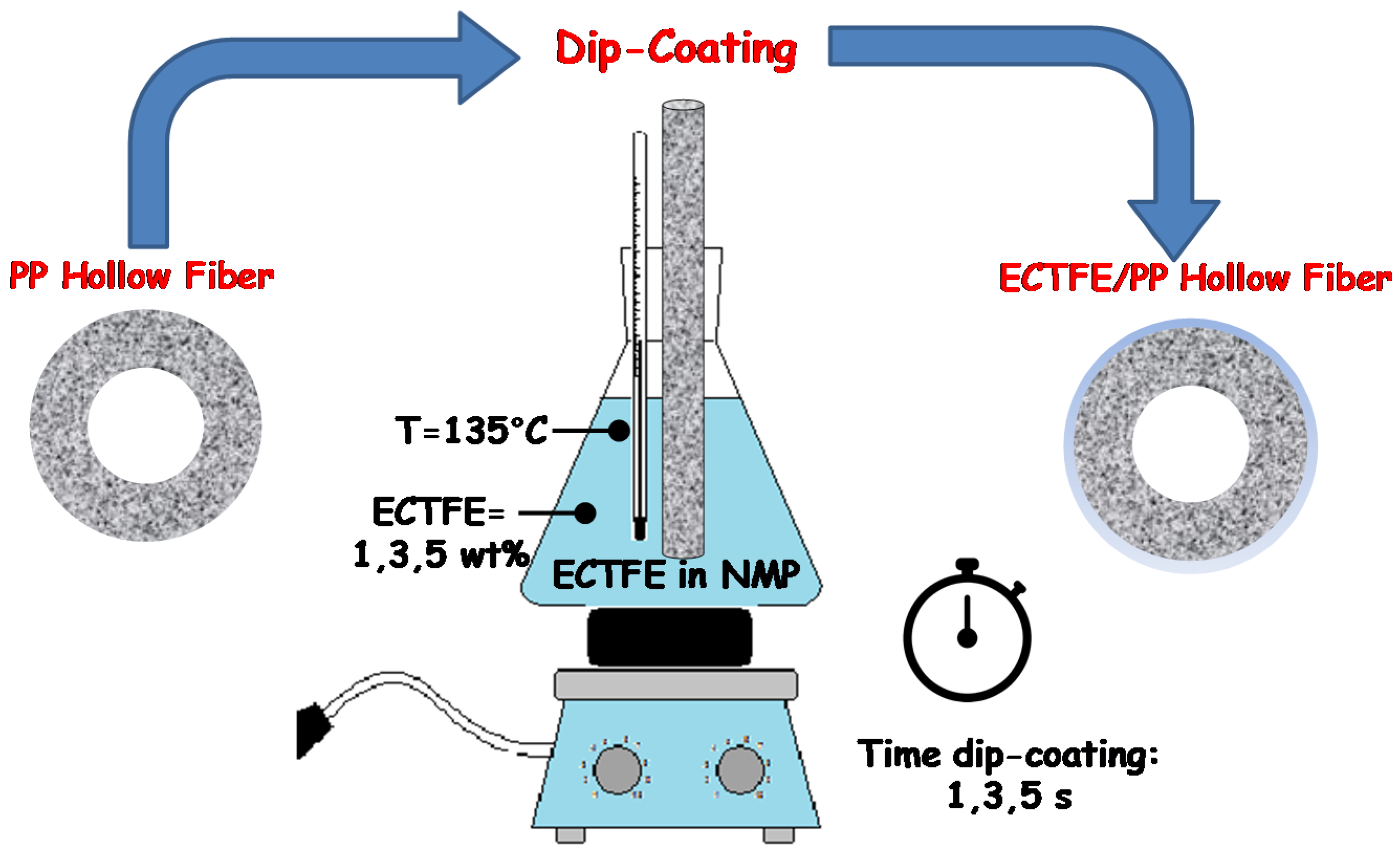
Polymeric dopes were prepared by mixing the polymer (ECTFE) at different concentrations (1, 3, and 5 wt %) in NMP. Briefly, the solvent was heated-up to a temperature of 135 °C and, then the pellets of ECTFE were slowly added keeping the solution under magnetic stirring (50 rpm). The polymeric solution was stirred at 135 °C for 5 h until the complete dissolution of the polymer was achieved. Subsequently the stirring was, then, stopped for 2 h in order to favor the removal of air bubbles.

2.3. Dip-Coating

Dip-coating method was used to coat the outer surface of PP hollow fiber membranes according to the procedure summarized in Figure 1. Before the process, the extremities of the fibers were sealed by an epoxy glue thus avoiding polymeric solution penetrating into the lumen of the fibers during the dip-coating procedure. Briefly, PP hollow fibers (10 cm of length) were vertically manually dipped into the polymeric solution. As soon as the hollow fibers were completely immersed in the ECTFE solution, the time of dip-coating started. In order to modulate the morphology of the coated layer of ECTFE, the time of dip-coating was varied from 1 s to 5 s. After coating, the fibers were dried at room temperature overnight and, subsequently, washed in water for 2–3 h and in ethanol overnight.
Finally, the membranes were dried for 5 h at 60 °C in an oven and for further 2 h in a vacuum furnace at 60 °C to remove the residual traces of solvent.

2.4. Characterization

2.4.1. Morphology and Thickness

The morphology of ECTFE/PP composite membranes and PP commercial hollow fibers were evaluated by using a scanning electron microscope (Cambridge Stereoscan 360, Cambridge Instrument, Somerville, MA, USA). The cross sections of novel coated membranes were prepared by freeze fracturing the samples in liquid nitrogen in order to produce a clean brittle fracture.
The diameters of ECTFE/PP composite hollow fibers and the thicknesses of ECTFE coating membranes were evaluated by means of a digital micrometer with a precision of ±0.0001 mm (Carl Mahr D 7300, Esslingen AN, Gottingen, Germany). For each sample, ten measurements were taken in order to evaluate the homogeneity of the coating.

2.4.2. Hydrophobicity

The hydrophobicity of the membranes was evaluated by contact angle measurements performed using ultrapure water by the method of the sessile drop (CAM100).
For each membrane 5 samples of 2 cm were cut and opened in order to fix with double-sided tape the inner surface of the fiber to set up the formation of a completely flat-surface, whereas the external one was available for the measurements of the contact angle.

2.4.3. Pore Size

Bubble point and pore size of both ECTFE/PP composite and PP hollow fiber membranes were measured by using a PMI capillary flow porometer (Porous Materials Inc., Ithaca, NY, USA).
Experiments were performed according to the procedure reported in the literature [23] using Porewick (surface tension = 16 dyn/cm) as wetting liquid and processing the data with the software Caprep (Porous Materials Inc., Ithaca, NY, USA).

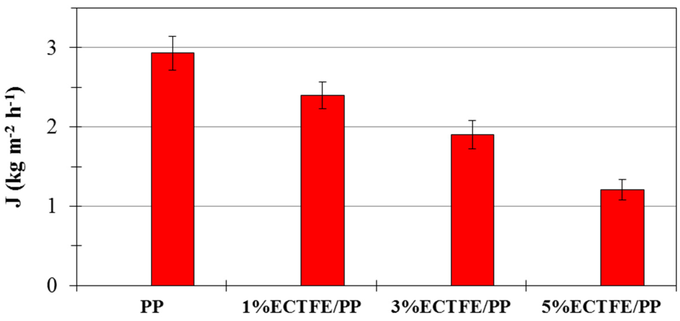
2.4.4. Water Permeability

Measurements of water permeability on PP and PP/ECTFE membranes were carried-out. Lab-made modules of an active area of ca. 7 cm2 were prepared by inserting 3 hollow fibers in a glass device; both extremities were sealed by epoxy glue.
The tests were performed by feeding double distilled water to the membrane module using the inside out configuration (feed solution in fiber lumen) at a temperature of 50 °C, feed flow rate of 1.42 L min−1 and a feed pressure of 2.2 bar. The permeate was collected and weighed to evaluate the flux. The flux was evaluated every 15 min for 3 h.

3. Results and Discussion

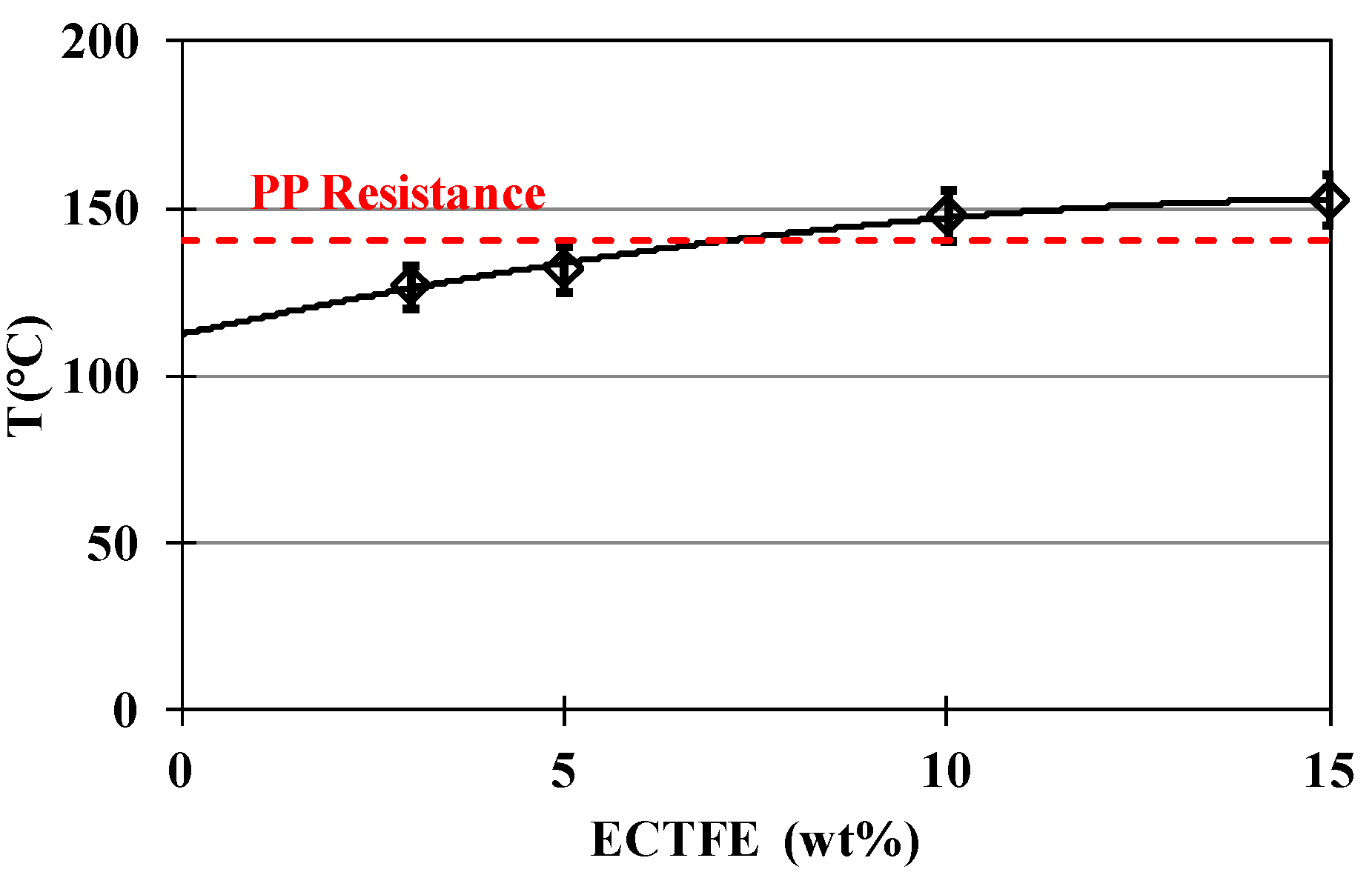
3.1. ECTFE Solubility

ECTFE solubility in NMP was evaluated by monitoring the cloud point (Cp) of polymeric solutions containing different ECTFE concentrations (Figure 2).
The TIPS process involves a polymer (i.e., ECTFE) that is not soluble in a diluent (i.e., NMP) at room temperature, but allows the preparation of a homogeneous polymeric solution at higher temperatures. When the dope solution is cooled, it undergoes liquid–liquid TIPS favoring the formation of a polymer enriched phase that solidifies as a consequence [24]. Figure 2 provides crucial information to the dynamics of nucleation, growth and solidification in the TIPS. In fact, for temperatures above the line delimited by the cloud point the system was stable, whereas once the dope solution was cooled-down at a temperature lower than the cloud point, TIPS occurred.
Moreover, preliminary experiments showed that the dipping of PP hollow fibers in NMP at 140 °C for a time lower than 5 s did not compromise the structure and the morphology of the support. On the other hand, the properties of PP hollow fibers are compromised for a contact time with solvent higher than 5 s. In particular, a decrease of the wall thickness and porosity combined with an enlargement of the pore size distribution were observed.
For this reason, attention was directed to the preparation of composite hollow fiber by dip-coating PP hollow-fibers in ECTFE polymeric solution (from 1 wt % to 5 wt %) in NMP at 135 °C varying the time of dip-coating from 1 to 5 s.

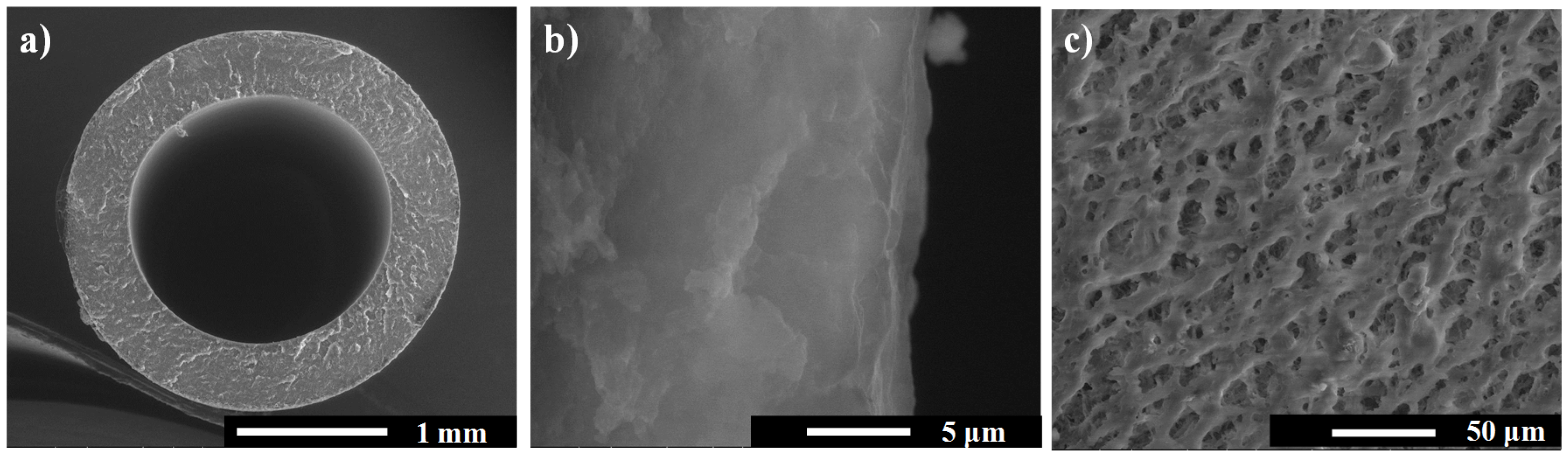
3.2. PP Hollow-Fibers

Polypropylene (PP) is a thermoplastic and isotactic polymer extensively employed in membrane technology because it combines economical viability with excellent properties, such as thermal, mechanical, and chemical resistance together with a hydrophobic nature.
The morphology of the PP fibers is depicted in Figure 3. PP hollow-fibers showed microporous sponge-like structure with a thickness of 450 μm and a lumen diameter of 1800 µm. (mean outer diameter of PP hollow fibers: 2700 µm).
PP membranes presented high hydrophobicity as a consequence of the hydrophobic nature of the material (PP): the contact angle resulted of 127° ± 4° (external surface). Moreover PP hollow-fibers present a narrow pore size distribution. In fact the pore size was evaluated to be of 0.404 ± 0.006 μm.

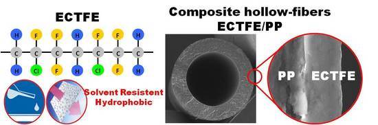
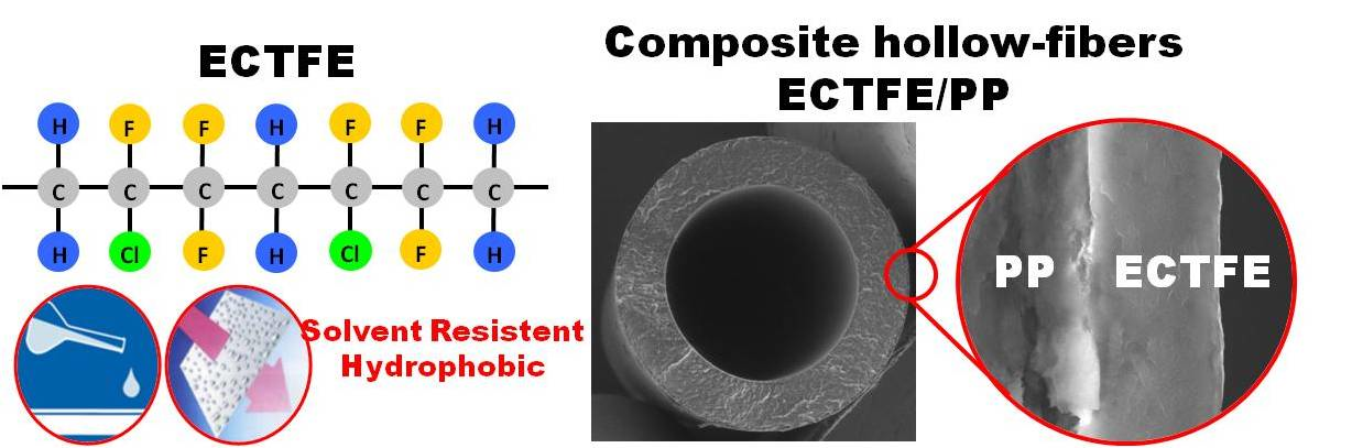
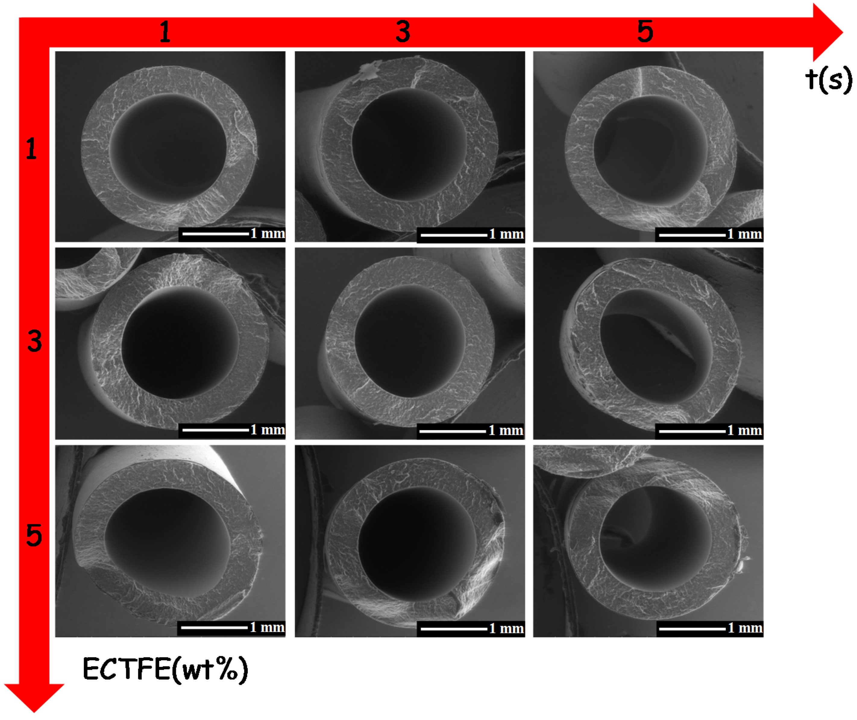
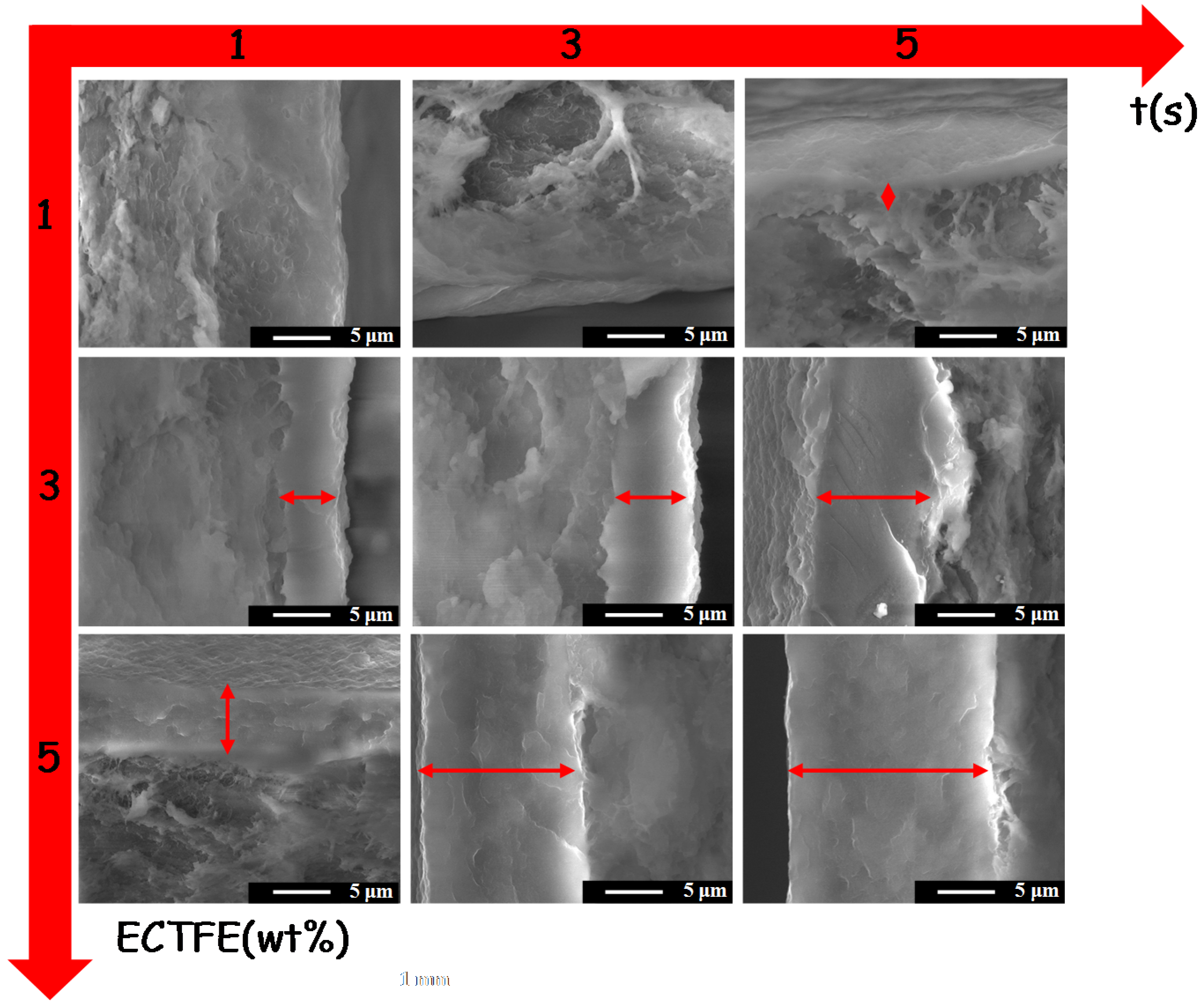
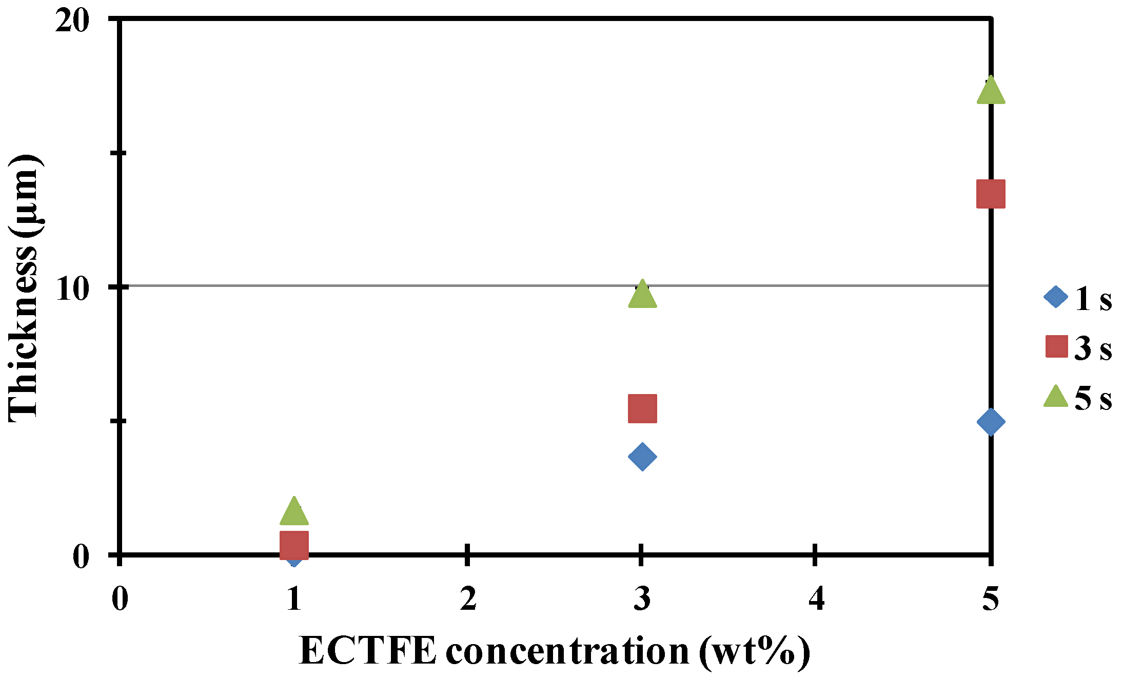
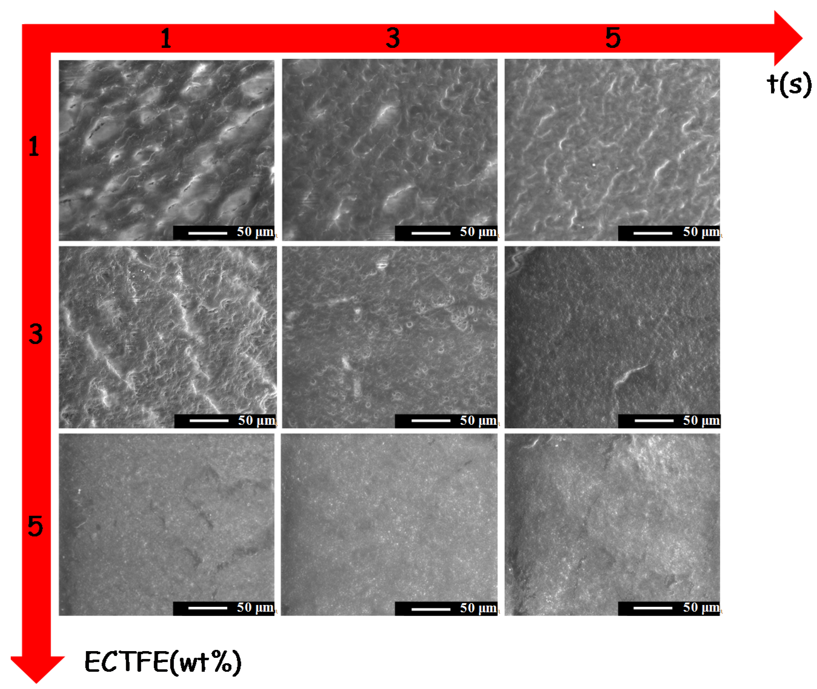
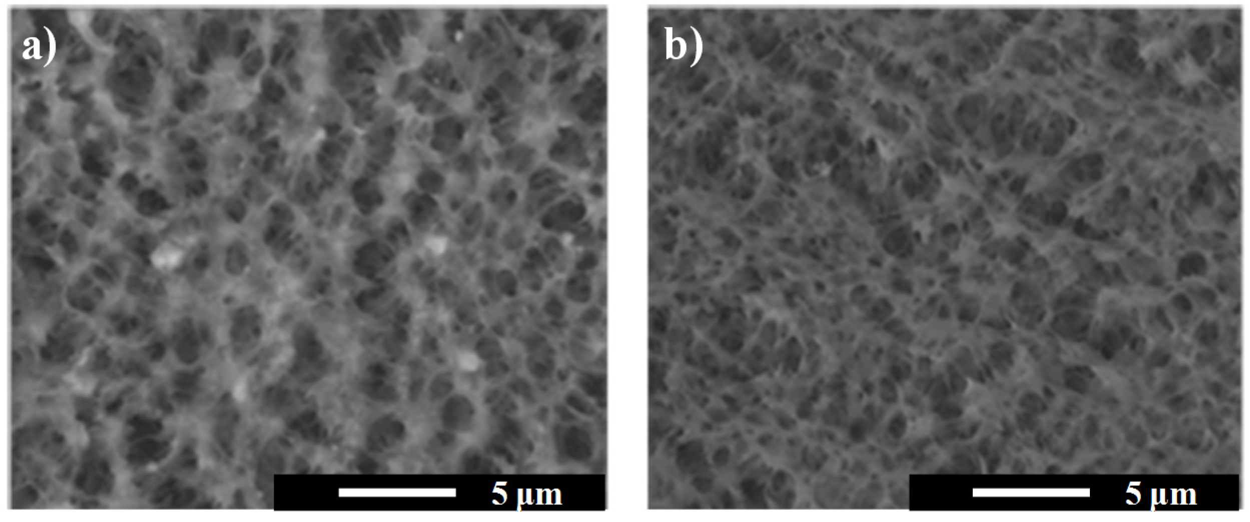
3.3. ECTFE/PP Composite Hollow Fiber

The membrane morphology was observed by using a scanning electron microscope (SEM) after the dip-coating process. By looking at Figure 4, it can be seen that the immersion of PP hollow-fibers in a polymeric solution of ECTFE (from 1 wt % to 5 wt %) in NMP at 135 °C did not compromise the shape and the morphology of the PP support. In fact, in all the cases, the morphology of ECTFE/PP composite fibers (Figure 4) is similar to PP hollow fibers without any treatment (Figure 3a), presenting a sponge-like microporous structure.
In Figure 5, SEM images of the zooms of the cross sections of the hollow-fibers near the external surfaces are shown. By looking at the magnification of the cross sections, the deposition of a thin layer of ECTFE on the PP support is evident. In particular, the thickness of the ECTFE coated layer increased with the time of the dip-coating treatment in the polymeric solution and concentration of ECTFE in NMP, as expected.
In fact, PP fibers immersed in solutions with low concentration of ECTFE (ECTFE concentration = 1 wt %) presented morphologies similar to the original PP fibers.
When the ECTFE concentration was increased from 1 wt % to 3 wt %, a well defined ECTFE layer on the PP support was easily distinguished from the porous support. Furthermore, the thickness of the ECTFE coating layer increased with the time of immersion in the polymeric solution. In fact; the thickness of the ECTFE skin increased from ca. 4 μm to ca. 10 µm with dip-coating time from 1 to 5 s (ECTFE concentration =3 wt %).
Further increase in the ECTFE concentration, up to 5 wt %, the thickness of ECTFE layer was estimated to be in the range of 5–17 µm and, also in this case, the thickness increased with the time of immersion in the ECTFE solution.
Moreover, measurements performed by means of a micrometer confirmed the homogeneity of ECTFE coatings. In fact, in all the cases the error on the thickness of the ECTFE coating is below 0.3 µm. The results are summarized in Figure 6 and evidence a linear effect of the concentration of ECTFE, solubilized in the polymeric solution employed for the dip coating, on the thickness of the ECTFE layer. Moreover, it is possible to notice the positive effect of the time of dip-coating on the thickness of ECTFE coating.
These results confirmed the effectiveness of the dip-coating process considering the low concentration of the coating agent (ECTFE) and the short time of the treatment (i.e., dip-coating). There are several parameters that positively contribute to the success of the coating [25,26,27]: (i) the PP hollow fibers employed as support; its roughness facilitated the immobilization of ECTFE, its hydrophobicity facilitated the adhesion with the coating agent, whereas the chemical and thermal stability of PP ensured the survival of the hollow fibers from the harsh condition of the dip-coating; (ii) the excellent film-forming properties of ECTFE allowed the preparation of homogeneous coatings for the preparation of the protection layers; (iii) the solvent NMP facilitated the solubility of ECTFE at low temperature and enabled the preparation of polymeric ECTFE solution that quickly underwent demixing as a consequence of decreasing temperature of a few degrees, thus facilitating the concentration of a solid phase of ECTFE on the PP hollow-fibers and, as a consequence, the formation of the ECTFE coatings.
Figure 7 shows the morphologies of the external surface of ECTFE/PP composite membranes. Comparing the surface of ECTFE/PP hollow-fibers (Figure 7) with the ones made of PP hollow fiber (Figure 3c); it can be seen that novel composite membranes present a less porous surface than PP hollow-fibers as a consequence of the deposition of ECTFE on the PP membrane support during the dip-coating process. This effect was also observed using the most diluted ECTFE polymeric solution (1 wt % of ECTFE).
The homogeneity of the coating increased with the ECTFE concentration as well as with the time of dip-coating of the PP membrane support in the polymeric solution, as expected, decreasing the roughness of the surface.
In Figure 8, the internal surfaces of PP support and ECTFE/PP composite hollow fiber prepared by dip-coating of the PP fibre for 5 s in a polymeric solution containing 5 wt % of ECTFE were compared. The SEM images showed that the inlet surfaces of PP support and composite fiber are similar, note that the dip-coating did not modify the properties of the PP support.
The bubble point of the membranes, and as a consequence the largest pore detected, is not influenced by the concentration of ECTFE in NMP and the time of dip coating. Furthermore, the largest pore of ECTFE/PP composite membranes was similar to the one measured for PP support (0.493 μm), except for ECTFE/PP composite fibers prepared using a time of dip-coating of 5 s and an ECTFE concentration of 1 wt %.
On the contrary, obvious differences were observed in the measurement of the mean pore size (Table 1). In fact, the deposition of the ECTFE on the external surface dramatically decreased the mean pore size: the mean pore size decreased, from ca. 0.4 μm for PP support to values lower than 0.2 μm for ECTFE/PP composite hollow-fibers.
Moreover, the pore size of the membrane was severely affected by the time of dip-coating and the ECTFE concentration. In fact the mean pore sizes of ECTFE/PP composite hollow-fibers range from 0.175 to 0.045 μm as a function of the operating conditions of the dip-coating. As a tendency, the mean pore decreased on increasing the time of dipping and the ECTFE concentration, as expected.
Measurements of contact angles were carried-out to evaluate variations in the chemical-physical properties of the external surface treated by dip-coating. PP porous hollow fiber presented a contact angle of ca. 126°. The deposition of ECTFE decreased the contact angle from 126° to 94° meanly due to decreasing the roughness of the external surface. In all cases, membranes were hydrophobic and the hydrophobicity of the novel composite ECTFE/PP membranes was not so much influenced by the time of dip-coating.
On the contrary, the contact angle of the fibers decreased with increasing ECTFE concentration in the polymeric solution used for dip-coating. Summarizing, the contact angles of the composite membranes are:
  • 114°–111° for PP membrane dipped in a solution containing 1 wt % ECTFE;
  • 109°–100° for PP membrane dipped in a solution containing 3 wt % ECTFE;
  • 95°–94° for PP membrane dipped in a solution containing 5 wt % ECTFE.
Moreover, composite membranes prepared using polymeric solution containing 5 wt % ECTFE presented contact angle close to the value of 99° observed for pure ECTFE films [10], indicating a high degree of coating of the support made of PP.
Decreasing of the contact angle is not related to an improvement in the hydrophilicity of the material, but is mainly due to decreasing the roughness of the membrane surface. In fact, the apparent contact angle (θ*) of a sessile droplet depends on the chemical texture of the surface as well its roughness (r) as proposed by Wenzel in the following equation:
cos(θ*) = r·cos(θ)
where θ is the ideal contact angle for a perfectly smooth surface (r = 1) [28].
This effect has been already reported in literature for ECTFE membranes [18,19,20]. For instance, Drioli et al. observed in asymmetric ECTFE flat-sheet membranes a difference of 21° between the contact angle of the smooth top-layer surface (θ* = 92°) and the one of the bottom surface with high roughness (θ* = 113°) [19].
In fact, ECTFE/PP composite membranes prepared using diluted concentration of ECTFE and short time of treatment (i.e., dip-coating) exhibited a hierarchical structure made of valleys entrapping air forming a gas-liquid interface with the feed solution, and resulting in a highly hydrophobic surface [25,26,27]. On the other hand, the hierarchical structure disappeared on increasing the concentration of ECTFE and time of dip-coating led to less porous and smoother surfaces with lower hydrophobic character.
According to Equation (1) and using as ideal contact angle for a perfectly smooth surface made of ECTFE the value of 92° [19], the roughness (r) of ECTFE coating dramatically decreased by increasing the time of dip-coating and ECTFE concentration. In fact the value of r lay between 11.6 and 10.3 as a function of the time of dip-coating for 1 wt % ECTFE/PP hollow fibers. In the case of 3 wt % ECTFE/PP composite hollow fibers, the roughness decreased to values ranging from 6.9 (1 s time of dip-coating) to 4.9 (5 s time of dip-coating). According to SEM pictures, the surface of 5 wt % ECTFE/PP hollow fibers actually appeared smooth. In fact the value of r was evaluated to be in the range of 2.5–1.5 when varying the time of dip-coating from 1 to 5 s.
PP hollow fibers presented a water transmembrane flux of 2.93 kg m−2 h−1 (Figure 9). ECTFE coatings reduced the flux of fibers, as expected, because of decreasing the surface porosity. Furthermore the increase of ECTFE concentration in the polymeric solution used for dip-coating treatment decreased the water flux (Figure 9) due to decreasing the pore size and increasing the thickness of the ECTFE layer. Moreover, in all the cases, the water flux was constant demonstrating an optimal adhesion of ECTFE on PP hollow fibers and a good stability of ECTFE coatings.
Although the ECTFE coating decreased the water flux, ECTFE/PP presented desirable morphological properties allowing the tailoring of the pore size dimension (from ca. 50 nm to ca. 200 nm) together with the smooth surfaces combined with the superior chemical resistance of ECTFE making them promising candidates for employing in organic solvent filtration [29], membrane contactor applications as bulk liquid membrane (BLM) extractants [30], lithium separator in a battery [31], and dialysis [32].

4. Conclusions

ECTFE was used as coating material to improve the chemical and thermal properties of porous commercial PP hollow fibers supplied by Membrana GmbH (Wuppertal, Germany).
PP was successfully used as membrane support in the dip-coating process using ECTFE as polymer and NMP as solvent (at a T = 135 °C). SEM analysis confirmed the deposition of ECTFE on the external surface without compromising the morphology of the support. ECTFE coating significantly decreased the mean pore size and the contact angle of the external surface that, in any case, maintained a hydrophobic character.
ECTFE/PP hollow-fibers showed a slightly lower water flux than PP hollow-fibers due to the extra-resistance to the ECTFE coating.
The ECTFE coating has the double function of both allowing the tailoring of the pore size of the new composite hollow-fiber membranes and effectively improving the chemical stability and the life of the starting PP membrane. Therefore, this novel membrane could be applied in the filtration of organic media and also for bulk liquid membrane (BLM) extractants.

Acknowledgements

The EU-FP7 is gratefully acknowledged for co-funding this work through the project ‘‘CapWa–Capture of evaporated water with novel membranes’’ (GA 246074).

Author Contributions

Sergio Santoro and Alberto Figoli developed the membranes, analyzed the measurement results and wrote the paper. Enrico Drioli was responsible for the actual realization and supervision of the work.

Conflicts of Interest

The authors declare no conflict of interest.

References

  1. Basu, S.; Maes, M.; Cano-Odena, A.; Alaerts, L.; De Vos, D.E.; Vankelecom, I.F.J. Solvent resistant nanofiltration (SRNF) membranes based on metal-organic frameworks. J. Membr. Sci. 2009, 344, 190–198. [Google Scholar] [CrossRef]
  2. Baker, R.W. Overview of Membrane Science and Technology. In Membrane Technology and Applications, 3rd ed.; Baker, R.W., Ed.; John Wiley & Sons, Ltd.: Chichester, UK, 2012; pp. 1–14. [Google Scholar]
  3. Uemura, T.; Henmi, M. Thin-Film Composite Membranes for Reverse Osmosis. In Advanced Membrane Technology and Applications; Li, N.N., Fane, A.G., Ho, W.S.W., Matsuura, T., Eds.; John Wiley & Sons, Ltd.: Chichester, UK, 2008; pp. 1–19. [Google Scholar]
  4. Koutsou, C.P.; Karabelas, A.J.; Kostoglou, M. Membrane desalination under constant water recovery—The effect of module design parameters on system performance. Sep. Purif. Technol. 2015, 147, 90–113. [Google Scholar] [CrossRef]
  5. Figoli, A.; Santoro, S.; Galiano, F.; Basile, A. Pervaporation membranes: Preparation and characterization. In Vapour Permeation and Membrane Distillation Principles and Applications; Basile, A., Figoli, A., Khayet, M., Eds.; Elsevier Woodhead Publishing: Kidlington, UK, 2015; pp. 19–63. [Google Scholar]
  6. Othman, R.; Mohammad, A.W.; Ismail, M.; Salimon, J. Application of polymeric solvent resistant nanofiltration membranes for biodiesel production. J. Membr. Sci. 2010, 348, 287–297. [Google Scholar] [CrossRef]
  7. Smitha, B.; Suhanya, D.; Sridhar, S.; Ramakrishna, M. Separation of organic–organic mixtures by pervaporation—A review. J. Membr. Sci. 2004, 241, 1–21. [Google Scholar] [CrossRef]
  8. Drobek, M.; Figoli, A.; Santoro, S.; Navascués, N.; Motuzas, J.; Simone, S.; Algieri, C.; Gaeta, N.; Querze, L.; Trotta, A.; et al. PVDF-MFI mixed matrix membranes as VOCs adsorbers. Microporous Mesoporous Mater. 2015, 207, 126–133. [Google Scholar] [CrossRef]
  9. Ramaiah, K.P.; Satyasri, D.; Sridhar, S.; Krishnaiah, A. Removal of hazardous chlorinated VOCs from aqueous solutions using novel ZSM-5 loaded PDMS/PVDF composite membrane consisting of three hydrophobic layers. J. Hazard. Mater. 2013, 261, 362–371. [Google Scholar] [CrossRef] [PubMed]
  10. Halar® ECTFE Ethylene-Chlorotrifluoroethylene Design and Processing Guide. Solvay Technical Sheets. Available online: http://www.solvaysolexis.com (accessed on 10 July 2016).
  11. Carretier, S.; Chen, L.-A.; Venault, A.; Yang, Z.-R.; Aimar, P.; Chang, Y. Design of PVDF/PEGMA-b-PS-b-PEGMA membranes by VIPS for improved biofouling mitigation. J. Membr. Sci. 2016, 510, 355–369. [Google Scholar] [CrossRef]
  12. Zhang, J.; Wang, Z.; Zhang, X.; Zheng, X.; Wu, Z. Enhanced antifouling behaviours of polyvinylidene fluoride membrane modified through blending with nano-TiO2/polyethylene glycol mixture. Appl. Surf. Sci. 2015, 345, 418–427. [Google Scholar] [CrossRef]
  13. Reid, K.; Dixon, M.; Pelekani, C.; Jarvis, K.; Willis, M.; Yu, Y. Biofouling control by hydrophilic surface modification of polypropylene feed spacers by plasma polymerisation. Desalination 2014, 335, 108–118. [Google Scholar] [CrossRef]
  14. Hausman, R.; Gullinkala, T.; Escobar, I.C. Development of copper-charged polypropylene feed spacers for biofouling control. J. Membr. Sci. 2010, 358, 114–121. [Google Scholar] [CrossRef]
  15. Roh, I.J.; Ramaswamy, S.; Krantz, W.B.; Greenberg, A.R. Poly(ethylene chlorotrifluoroethylene) membrane formation via thermally induced phase separation (TIPS). J. Membr. Sci. 2010, 362, 211–220. [Google Scholar] [CrossRef]
  16. Müller, H.-J. A new solvent resistant membrane based on ECTFE. Desalination 2006, 199, 191–192. [Google Scholar] [CrossRef]
  17. Ramaswamy, S.; Greenberg, A.R.; Krantz, W.B. Fabrication of poly (ECTFE) membranes via thermally induced phase separation. J. Membr. Sci. 2002, 210, 175–180. [Google Scholar] [CrossRef]
  18. Simone, S.; Figoli, A.; Santoro, S.; Galiano, F.; Alfadul, S.M.; Al-Harbi, O.A.; Drioli, E. Preparation and characterization of ECTFE solvent resistant membranes and their application in pervaporation of toluene/water mixtures. Sep. Purif. Technol. 2012, 90, 147–161. [Google Scholar] [CrossRef]
  19. Drioli, E.; Santoro, S.; Simone, S.; Barbieri, G.; Brunetti, A.; Macedonio, F.; Figoli, A. ECTFE membrane preparation for recovery of humidified gas streams using membrane condenser. React. Funct. Polym. 2014, 79, 1–7. [Google Scholar] [CrossRef]
  20. Ursino, C.; Simone, S.; Donato, L.; Santoro, S.; De Santo, M.P.; Drioli, E.; Di Nicolò, E.; Figoli, A. ECTFE membranes produced by non-toxic diluents for organic solvent filtration separation. RSC Adv. 2016, 6, 81001–81012. [Google Scholar] [CrossRef]
  21. Pan, J.; Xiao, C.; Huang, Q.; Wang, C.; Liu, H.; Hu, J. ECTFE porous membranes with conveniently controlled microstructures for vacuum membrane distillation. J. Mater. Chem. A 2015, 3, 45249–45257. [Google Scholar] [CrossRef]
  22. Zhou, B.; Li, Q.; Tang, Y.; Lin, Y.; Wang, X. Preparation of ECTFE membranes with bicontinuous structure via TIPS method by a binary diluent. Desalin. Water Treat. 2016, 57, 17646–17657. [Google Scholar] [CrossRef]
  23. Wang, K.; Chung, T.; Gryta, M. Hydrophobic PVDF hollow fiber membranes with narrow pore size distribution and ultra-skin for the fresh water production through membrane distillation. Chem. Eng. Sci. 2008, 63, 2587–2594. [Google Scholar] [CrossRef]
  24. Atkinson, P.M.; Lloyd, D.R. Anisotropic flat sheet membrane formation via TIPS: thermal effects. J. Membr. Sci. 2000, 171, 1–18. [Google Scholar] [CrossRef]
  25. Lu, K.J.; Zuo, J.; Chung, T.S. Tri-bore PVDF hollow fibers with a super-hydrophobic coating for membrane distillation. J. Membr. Sci. 2016, 514, 165–175. [Google Scholar] [CrossRef]
  26. Hou, D.; Wang, J.; Sun, X.; Ji, Z.; Luan, Z. Preparation and properties of PVDF composite hollow fiber membranes for desalination through direct contact membrane distillation. J. Membr. Sci. 2012, 405–406, 185–200. [Google Scholar] [CrossRef]
  27. Rafat, M.; De, D.; Khulbe, K.C.; Nguyen, T.; Matsuura, T. Surface characterization of hollow fiber membranes used in artificial kidney. J. Appl. Polym. Sci. 2006, 101, 4386–4400. [Google Scholar] [CrossRef]
  28. Wenzel, R.N. Resistance of solid surface to wetting by water. Ind. Eng. Chem. 1936, 28, 988–994. [Google Scholar] [CrossRef]
  29. Amirilargani, M.; Sadrzadeh, M.; Sudhölter, E.J.R.; de Smet, L.C.P.M. Surface modification methods of organic solvent nanofiltration membranes. Chem. Eng. J. 2010, 289, 562–582. [Google Scholar] [CrossRef]
  30. Abdel-Aal, E.A.; Mahmoud, M.H.H.; Sanad, M.M.S.; Criscuoli, A.; Figoli, A.; Drioli, E. Membrane contactor as a novel technique for separation of iron ions from ilmenite leachant. Int. J. Miner. Process 2010, 96, 62–69. [Google Scholar] [CrossRef]
  31. Zhang, S.S. A review on the separators of liquid electrolyte Li-ion batteries. J. Power Sources 2007, 164, 351–364. [Google Scholar] [CrossRef]
  32. Zhang, Q.; Lu, X.; Zhao, L. Preparation of Polyvinylidene Fluoride (PVDF) Hollow Fiber Hemodialysis. Membranes 2014, 4, 81–95. [Google Scholar] [CrossRef] [PubMed]
Figure 1. Scheme of dip-coating procedure.
Coatings 06 00040 g001
Figure 2. Cloud points of ECTFE solutions as a function of polymer concentration.
Coatings 06 00040 g002
Figure 3. Scanning electron microscopy (SEM) images of PP hollow fibers. From left to right: cross section (a) 80× and (b) 1000× and (c) external surface 1000×.
Coatings 06 00040 g003
Figure 4. SEM images (magnification 80×) of composite ECTFE/PP hollow fibers as a function of ECTFE concentration (1 wt %, 3 wt %, 5 wt %) and time of dip-coating (1 s, 3 s, 5 s).
Coatings 06 00040 g004
Figure 5. SEM images (magnification 10000×) of the cross section of composite ECTFE/PP hollow-fibers as a function of ECTFE concentration (1 wt %, 3 wt %, 5 wt %) and time of dip-coating (1 s, 3 s, 5 s).
Coatings 06 00040 g005
Figure 6. Effect of the ECTFE concentration and the time of dip-coating on the thickness of ECTFE coating.
Coatings 06 00040 g006
Figure 7. SEM images (magnification 1000×) of the external surface of composite ECTFE/PP hollow fibers as a function of ECTFE concentration (1 wt %, 3 wt %, 5 wt %) and time of dip-coating (1 s, 3 s, 5 s).
Coatings 06 00040 g007
Figure 8. SEM images (magnification 10000×) of the internal surface. From left to right: PP support and ECTFE/PP composite fiber (ECTFE concentration = 5 wt %, time of dip coating = 5 s).
Coatings 06 00040 g008
Figure 9. Water fluxes of PP hollow fiber and PP/ECTFE composite hollow-fibers.
Coatings 06 00040 g009
Table 1. Membrane characterization as a function of the time of dipping, t, and ECTFE concentration.
ECTFE (wt%)t (s)CA (°) dp (μm)dLp (μm)
00126 ± 30.401 ± 0.0060.493 ± 0.017
11114 ± 20.175 ± 0.0110.441 ± 0.027
13113 ± 30.150 ± 0.0090.464 ± 0.012
15111 ± 30.133 ± 0.0080.486 ± 0.024
31104 ± 40.138 ± 0.0100.461 ± 0.027
33107 ± 50.088 ± 0.0070.447 ± 0.012
35100 ± 10.055 ± 0.0030.511 ± 0.033
5195 ± 20.095 ± 0.0080.501 ± 0.019
5394 ± 30.053 ± 0.0030.488 ± 0.022
5593 ± 20.047 ± 0.0040.448 ± 0.021
CA: contact angle, dp: mean pore, dLp: largest pore detected.

